EP3473453B1 - Schwerlastluftreifen - Google Patents
Schwerlastluftreifen Download PDFInfo
- Publication number
- EP3473453B1 EP3473453B1 EP16906358.3A EP16906358A EP3473453B1 EP 3473453 B1 EP3473453 B1 EP 3473453B1 EP 16906358 A EP16906358 A EP 16906358A EP 3473453 B1 EP3473453 B1 EP 3473453B1
- Authority
- EP
- European Patent Office
- Prior art keywords
- belt layer
- reinforcing elements
- tire
- belt
- layer
- Prior art date
- Legal status (The legal status is an assumption and is not a legal conclusion. Google has not performed a legal analysis and makes no representation as to the accuracy of the status listed.)
- Active
Links
Images

Classifications
-
- B—PERFORMING OPERATIONS; TRANSPORTING
- B60—VEHICLES IN GENERAL
- B60C—VEHICLE TYRES; TYRE INFLATION; TYRE CHANGING; CONNECTING VALVES TO INFLATABLE ELASTIC BODIES IN GENERAL; DEVICES OR ARRANGEMENTS RELATED TO TYRES
- B60C15/00—Tyre beads, e.g. ply turn-up or overlap
- B60C15/0009—Tyre beads, e.g. ply turn-up or overlap features of the carcass terminal portion
- B60C15/0027—Tyre beads, e.g. ply turn-up or overlap features of the carcass terminal portion with low ply turn-up, i.e. folded around the bead core and terminating at the bead core
-
- B—PERFORMING OPERATIONS; TRANSPORTING
- B60—VEHICLES IN GENERAL
- B60C—VEHICLE TYRES; TYRE INFLATION; TYRE CHANGING; CONNECTING VALVES TO INFLATABLE ELASTIC BODIES IN GENERAL; DEVICES OR ARRANGEMENTS RELATED TO TYRES
- B60C9/00—Reinforcements or ply arrangement of pneumatic tyres
- B60C9/18—Structure or arrangement of belts or breakers, crown-reinforcing or cushioning layers
- B60C9/28—Structure or arrangement of belts or breakers, crown-reinforcing or cushioning layers characterised by the belt or breaker dimensions or curvature relative to carcass
-
- B—PERFORMING OPERATIONS; TRANSPORTING
- B60—VEHICLES IN GENERAL
- B60C—VEHICLE TYRES; TYRE INFLATION; TYRE CHANGING; CONNECTING VALVES TO INFLATABLE ELASTIC BODIES IN GENERAL; DEVICES OR ARRANGEMENTS RELATED TO TYRES
- B60C11/00—Tyre tread bands; Tread patterns; Anti-skid inserts
-
- B—PERFORMING OPERATIONS; TRANSPORTING
- B60—VEHICLES IN GENERAL
- B60C—VEHICLE TYRES; TYRE INFLATION; TYRE CHANGING; CONNECTING VALVES TO INFLATABLE ELASTIC BODIES IN GENERAL; DEVICES OR ARRANGEMENTS RELATED TO TYRES
- B60C11/00—Tyre tread bands; Tread patterns; Anti-skid inserts
- B60C11/0083—Tyre tread bands; Tread patterns; Anti-skid inserts characterised by the curvature of the tyre tread
-
- B—PERFORMING OPERATIONS; TRANSPORTING
- B60—VEHICLES IN GENERAL
- B60C—VEHICLE TYRES; TYRE INFLATION; TYRE CHANGING; CONNECTING VALVES TO INFLATABLE ELASTIC BODIES IN GENERAL; DEVICES OR ARRANGEMENTS RELATED TO TYRES
- B60C15/00—Tyre beads, e.g. ply turn-up or overlap
- B60C15/0009—Tyre beads, e.g. ply turn-up or overlap features of the carcass terminal portion
-
- B—PERFORMING OPERATIONS; TRANSPORTING
- B60—VEHICLES IN GENERAL
- B60C—VEHICLE TYRES; TYRE INFLATION; TYRE CHANGING; CONNECTING VALVES TO INFLATABLE ELASTIC BODIES IN GENERAL; DEVICES OR ARRANGEMENTS RELATED TO TYRES
- B60C9/00—Reinforcements or ply arrangement of pneumatic tyres
- B60C9/18—Structure or arrangement of belts or breakers, crown-reinforcing or cushioning layers
-
- B—PERFORMING OPERATIONS; TRANSPORTING
- B60—VEHICLES IN GENERAL
- B60C—VEHICLE TYRES; TYRE INFLATION; TYRE CHANGING; CONNECTING VALVES TO INFLATABLE ELASTIC BODIES IN GENERAL; DEVICES OR ARRANGEMENTS RELATED TO TYRES
- B60C9/00—Reinforcements or ply arrangement of pneumatic tyres
- B60C9/18—Structure or arrangement of belts or breakers, crown-reinforcing or cushioning layers
- B60C9/20—Structure or arrangement of belts or breakers, crown-reinforcing or cushioning layers built-up from rubberised plies each having all cords arranged substantially parallel
-
- B—PERFORMING OPERATIONS; TRANSPORTING
- B60—VEHICLES IN GENERAL
- B60C—VEHICLE TYRES; TYRE INFLATION; TYRE CHANGING; CONNECTING VALVES TO INFLATABLE ELASTIC BODIES IN GENERAL; DEVICES OR ARRANGEMENTS RELATED TO TYRES
- B60C9/00—Reinforcements or ply arrangement of pneumatic tyres
- B60C9/18—Structure or arrangement of belts or breakers, crown-reinforcing or cushioning layers
- B60C9/20—Structure or arrangement of belts or breakers, crown-reinforcing or cushioning layers built-up from rubberised plies each having all cords arranged substantially parallel
- B60C2009/2012—Structure or arrangement of belts or breakers, crown-reinforcing or cushioning layers built-up from rubberised plies each having all cords arranged substantially parallel with particular configuration of the belt cords in the respective belt layers
- B60C2009/2016—Structure or arrangement of belts or breakers, crown-reinforcing or cushioning layers built-up from rubberised plies each having all cords arranged substantially parallel with particular configuration of the belt cords in the respective belt layers comprising cords at an angle of 10 to 30 degrees to the circumferential direction
-
- B—PERFORMING OPERATIONS; TRANSPORTING
- B60—VEHICLES IN GENERAL
- B60C—VEHICLE TYRES; TYRE INFLATION; TYRE CHANGING; CONNECTING VALVES TO INFLATABLE ELASTIC BODIES IN GENERAL; DEVICES OR ARRANGEMENTS RELATED TO TYRES
- B60C9/00—Reinforcements or ply arrangement of pneumatic tyres
- B60C9/18—Structure or arrangement of belts or breakers, crown-reinforcing or cushioning layers
- B60C9/20—Structure or arrangement of belts or breakers, crown-reinforcing or cushioning layers built-up from rubberised plies each having all cords arranged substantially parallel
- B60C2009/2012—Structure or arrangement of belts or breakers, crown-reinforcing or cushioning layers built-up from rubberised plies each having all cords arranged substantially parallel with particular configuration of the belt cords in the respective belt layers
- B60C2009/2019—Structure or arrangement of belts or breakers, crown-reinforcing or cushioning layers built-up from rubberised plies each having all cords arranged substantially parallel with particular configuration of the belt cords in the respective belt layers comprising cords at an angle of 30 to 60 degrees to the circumferential direction
-
- B—PERFORMING OPERATIONS; TRANSPORTING
- B60—VEHICLES IN GENERAL
- B60C—VEHICLE TYRES; TYRE INFLATION; TYRE CHANGING; CONNECTING VALVES TO INFLATABLE ELASTIC BODIES IN GENERAL; DEVICES OR ARRANGEMENTS RELATED TO TYRES
- B60C9/00—Reinforcements or ply arrangement of pneumatic tyres
- B60C9/18—Structure or arrangement of belts or breakers, crown-reinforcing or cushioning layers
- B60C9/20—Structure or arrangement of belts or breakers, crown-reinforcing or cushioning layers built-up from rubberised plies each having all cords arranged substantially parallel
- B60C2009/2012—Structure or arrangement of belts or breakers, crown-reinforcing or cushioning layers built-up from rubberised plies each having all cords arranged substantially parallel with particular configuration of the belt cords in the respective belt layers
- B60C2009/2022—Structure or arrangement of belts or breakers, crown-reinforcing or cushioning layers built-up from rubberised plies each having all cords arranged substantially parallel with particular configuration of the belt cords in the respective belt layers comprising cords at an angle of 60 to 90 degrees to the circumferential direction
-
- B—PERFORMING OPERATIONS; TRANSPORTING
- B60—VEHICLES IN GENERAL
- B60C—VEHICLE TYRES; TYRE INFLATION; TYRE CHANGING; CONNECTING VALVES TO INFLATABLE ELASTIC BODIES IN GENERAL; DEVICES OR ARRANGEMENTS RELATED TO TYRES
- B60C9/00—Reinforcements or ply arrangement of pneumatic tyres
- B60C9/18—Structure or arrangement of belts or breakers, crown-reinforcing or cushioning layers
- B60C9/20—Structure or arrangement of belts or breakers, crown-reinforcing or cushioning layers built-up from rubberised plies each having all cords arranged substantially parallel
- B60C2009/2074—Physical properties or dimension of the belt cord
- B60C2009/2077—Diameters of the cords; Linear density thereof
-
- B—PERFORMING OPERATIONS; TRANSPORTING
- B60—VEHICLES IN GENERAL
- B60C—VEHICLE TYRES; TYRE INFLATION; TYRE CHANGING; CONNECTING VALVES TO INFLATABLE ELASTIC BODIES IN GENERAL; DEVICES OR ARRANGEMENTS RELATED TO TYRES
- B60C2200/00—Tyres specially adapted for particular applications
- B60C2200/06—Tyres specially adapted for particular applications for heavy duty vehicles
-
- B—PERFORMING OPERATIONS; TRANSPORTING
- B60—VEHICLES IN GENERAL
- B60C—VEHICLE TYRES; TYRE INFLATION; TYRE CHANGING; CONNECTING VALVES TO INFLATABLE ELASTIC BODIES IN GENERAL; DEVICES OR ARRANGEMENTS RELATED TO TYRES
- B60C9/00—Reinforcements or ply arrangement of pneumatic tyres
- B60C9/18—Structure or arrangement of belts or breakers, crown-reinforcing or cushioning layers
- B60C9/20—Structure or arrangement of belts or breakers, crown-reinforcing or cushioning layers built-up from rubberised plies each having all cords arranged substantially parallel
- B60C9/2003—Structure or arrangement of belts or breakers, crown-reinforcing or cushioning layers built-up from rubberised plies each having all cords arranged substantially parallel characterised by the materials of the belt cords
- B60C9/2006—Structure or arrangement of belts or breakers, crown-reinforcing or cushioning layers built-up from rubberised plies each having all cords arranged substantially parallel characterised by the materials of the belt cords consisting of steel cord plies only
-
- Y—GENERAL TAGGING OF NEW TECHNOLOGICAL DEVELOPMENTS; GENERAL TAGGING OF CROSS-SECTIONAL TECHNOLOGIES SPANNING OVER SEVERAL SECTIONS OF THE IPC; TECHNICAL SUBJECTS COVERED BY FORMER USPC CROSS-REFERENCE ART COLLECTIONS [XRACs] AND DIGESTS
- Y02—TECHNOLOGIES OR APPLICATIONS FOR MITIGATION OR ADAPTATION AGAINST CLIMATE CHANGE
- Y02T—CLIMATE CHANGE MITIGATION TECHNOLOGIES RELATED TO TRANSPORTATION
- Y02T10/00—Road transport of goods or passengers
- Y02T10/80—Technologies aiming to reduce greenhouse gasses emissions common to all road transportation technologies
- Y02T10/86—Optimisation of rolling resistance, e.g. weight reduction
Definitions
- the present invention relates to a heavy-duty pneumatic tire.
- a belt having a plurality of belt layers is provided further outward in the tire radial direction than the crown portion of the carcass to improve durability, to preserve the tire shape when the tire is filled to a high internal pressure, and to improve the uneven wear resistance by controlling radial growth.
- PTL patent literature
- the present invention aims to provide a heavy-duty pneumatic tire with reduced rolling resistance.
- a summary of the present invention is as follows.
- a heavy-duty pneumatic tire according to the present invention is as claimed in claim 1.
- Preferred embodiments of the present invention are defined in the dependent claims.
- the "inclination angle” and the “shortest distance” refer to the inclination angle and the shortest distance in a reference state in which the heavy-duty pneumatic tire is assembled with an applicable rim and inflated to the prescribed internal pressure with no load thereon.
- the "shortest distance” refers to the shortest distance between surfaces of the reinforcing elements.
- the "applicable rim” refers to a standard rim of an applicable size, such as the Measuring Rim in the STANDARDS MANUAL of the European Tire and Rim Technological Organization (ETRTO) in Europe or the Design Rim in the YEAR BOOK of the Tire and Rim Association, Inc. (TRA) in the USA, that is described in industrial standards effective in the region where the tire is manufactured and used, such as the JATMA YEAR BOOK published by the Japan Automobile Tyre Manufacturers Association (JATMA) in Japan, the STANDARDS MANUAL of the ETRTO, and the YEAR BOOK of the TRA.
- ETRTO European Tire and Rim Technological Organization
- TRA Design Rim in the YEAR BOOK of the Tire and Rim Association, Inc.
- the "prescribed internal pressure” represents the internal air pressure corresponding to the maximum load capability for each applicable size and ply rating prescribed by the aforementioned JATMA YEAR BOOK and the like.
- the "maximum load capability” represents the maximum mass, under the aforementioned standards, permitted to be loaded on the tire.
- the "tread thickness” refers to the distance in the tire radial direction, at the tire equatorial plane, from the surface of the tread to the tire inner surface in the reference state.
- the tread thickness refers to the distance in the tire radial direction, at the tire equatorial plane, from the imaginary profile line to the tire inner surface.
- the present invention can provide a heavy-duty pneumatic tire with reduced rolling resistance.
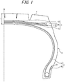
- FIG. 1 is a partial cross-sectional view in the tire width direction of a heavy-duty pneumatic tire (also simply "tire") according to an embodiment of the present invention.
- FIG. 1 illustrates only one of two halves of the tire, separated in the tire width direction by the tire equatorial plane CL, but the other half has a similar structure.
- FIG. 1 depicts the tire in a state where the tire has been assembled with an applicable rim and inflated to the prescribed internal pressure with no load thereon.
- a tire 1 of the present embodiment includes a carcass 2, a belt 3, and a tread 4.
- the carcass 2 extends toroidally between bead cores embedded in a pair of bead portions.
- the belt 3 and the tread 4, in this order, are further outward in the tire radial direction than a crown portion of the carcass 2.
- the carcass 2 is composed of a pair of carcass plies, but the number of carcass plies may be more than two as necessary.
- the cords in the carcass 2 may be made of any material.
- metal fiber cords such as steel cords may be used.
- the carcass 2 is made of a carcass body 2a extending toroidally between the pair of bead portions and carcass folded-up portions 2b extending from the carcass body 2a and folded up at the bead portions from the inside to the outside in the tire width direction.
- a tire radial outer edge 2b1 of the carcass folded-up portion 2b is located further inward in the tire radial direction than a tire maximum width position M.
- the belt 3 is made of four belt layers 3a to 3d.
- a first belt layer 3c and a second belt layer 3b which is located further inward in the tire radial direction than the first belt layer 3c (adjacent to the first belt layer 3c in this example), form a two-layered inclined belt 3bc.
- a single-layer outer belt layer 3d is located further outward in the tire radial direction than the inclined belt 3bc.
- a single-layer inner belt layer 3a is located further inward in the tire radial direction than the inclined belt 3bc.
- the number of belt layers in the present embodiment is four. To improve tire durability, the number of belt layers located further outward or inward in the tire radial direction from the inclined belt 3bc may be increased for a total of five or more belt layers.
- FIG. 2 schematically illustrates the belt structure of the heavy-duty pneumatic tire in FIG. 1 .
- reinforcing elements of the first belt layer 3c and reinforcing elements of the second belt layer 3b extend at an inclination angle of 5° to 30° relative to the tire circumferential direction in such a manner that the reinforcing elements of the first belt layer 3c cross the reinforcing elements of the second belt layer 3b.
- FIG. 2 schematically illustrates the belt structure of the heavy-duty pneumatic tire in FIG. 1 .
- reinforcing elements of the first belt layer 3c and reinforcing elements of the second belt layer 3b extend at an inclination angle of 5° to 30° relative to the tire circumferential direction in such a manner that the reinforcing elements of the first belt layer 3c cross the reinforcing elements of the second belt layer 3b.
- the reinforcing elements of the first belt layer 3c and the reinforcing elements of the second belt layer 3b extend at the same inclination angle relative to the tire circumferential direction in opposite directions in such a manner that the reinforcing elements of the first belt layer 3c cross the reinforcing elements of the second belt layer 3b.
- the reinforcing elements of the first belt layer 3c and the reinforcing elements of the second belt layer 3b may extend at different inclination angles relative to the tire circumferential direction in opposite directions in such a manner that the reinforcing elements of the first belt layer 3c cross the reinforcing elements of the second belt layer 3b.
- the reinforcing elements of the first belt layer 3c and the reinforcing elements of the second belt layer 3b may also extend at different inclination angles relative to the tire circumferential direction in the same direction (with one side in the tire circumferential direction of the reinforcing elements in each layer being inclined towards the same side in the tire width direction) in such a manner that the reinforcing elements of the first belt layer 3c cross the reinforcing elements of the second belt layer 3b.
- the reinforcing elements are steel cords, but cords of a different material or filament may also be used.
- the inclination angle of the reinforcing elements of the outer belt layer 3d relative to the tire circumferential direction is greater than the inclination angle of the reinforcing elements of the first belt layer 3c and the reinforcing elements of the second belt layer 3b relative to the tire circumferential direction, as illustrated in FIG. 2 .
- the inclination angle of the reinforcing elements of the inner belt layer 3a relative to the tire circumferential direction is greater than the inclination angle of the reinforcing elements of the first belt layer 3c and the second belt layer 3b relative to the tire circumferential direction, as illustrated in FIG. 2 .
- the reinforcing elements of the outer belt layer 3d and the reinforcing elements of the inner belt layer 3a extend at the same inclination angle relative to the tire circumferential direction in opposite directions in such a manner that the reinforcing elements of the outer belt layer 3d cross the reinforcing elements of the inner belt layer 3a, as illustrated in FIG. 2 .
- the reinforcing elements of the outer belt layer 3d and the reinforcing elements of the inner belt layer 3a may extend at different inclination angles relative to the tire circumferential direction in opposite directions in such a manner that the reinforcing elements of the outer belt layer 3d cross the reinforcing elements of the inner belt layer 3a.
- the reinforcing elements of the outer belt layer 3d and the reinforcing elements of the inner belt layer 3a may also extend at different inclination angles relative to the tire circumferential direction in the same direction (with one side in the tire circumferential direction of the reinforcing elements in each layer being inclined towards the same side in the tire width direction) in such a manner that the reinforcing elements of the outer belt layer 3d cross the reinforcing elements of the inner belt layer 3a.
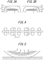
- FIG. 3A is a partial cross-sectional view in the tire width direction of an example of a known heavy-duty pneumatic tire
- FIG. 3B is a partial cross-sectional view in the tire width direction of a heavy-duty pneumatic tire according to an embodiment of the present disclosure.
- FIG. 4 illustrates the distance between reinforcing elements of the first belt layer and reinforcing elements of the second belt layer.
- the tire of the present embodiment includes four belt layers 3a to 3d as the belt 3, thereby increasing the tire durability even under a heavy load and maintaining the tire shape when the tire is filled to a high internal pressure. Furthermore, this structure can control radial growth and improve uneven wear resistance.
- FIG. 5 illustrates the neutral axis of bending deformation of the belt layer when the tire rolls under a load.
- the neutral axis of bending deformation of the belt layer when the tire rolls under a load is located between the belt layers 3c, 3b that form the inclined belt 3bc, as illustrated in FIG. 5 .
- the neutral axis of bending deformation is located between the belt layers 3c, 3b forming the inclined belt 3bc when the inclination angle relative to the tire circumferential direction of the reinforcing elements of the outer belt layer and the inclination angle relative to the tire circumferential direction of the reinforcing elements of the inner belt layer 3a are greater than the inclination angle relative to the tire circumferential direction of the reinforcing elements of the first belt layer 3c and the reinforcing elements of the second belt layer 3b.
- the shortest distance d in the tire of the present embodiment is 0.64 mm or less, which allows a reduction in the sum of i) the distance between the central axis of the bending deformation and the reinforcing elements of the first belt layer 3c and ii) the distance between the central axis of the bending and the reinforcing elements of the second belt layer 3b. This also allows a reduction in the compressive and tensile forces experienced by the reinforcing elements of the inclined belt 3bc and a reduction in the distortion energy loss of rubber between the reinforcing elements of the first belt layer 3c and the reinforcing elements of the second belt layer 3b, thereby reducing the rolling resistance.
- the tire of the present embodiment can improve the durability of the reinforcing elements by reducing the compressive and tensile forces experienced by the reinforcing elements of the inclined belt 3bc.
- the tire of the present embodiment thus uses the four belt layers 3a to 3d to ensure the aforementioned properties of a heavy-duty pneumatic tire while reducing the energy loss of rubber in the inclined belt 3bc to reduce the rolling resistance. At this time, the tire of the present embodiment also ensures durability of the reinforcing elements.
- the shortest distance d is more preferably 0.60 mm or less.
- the shortest distance d is 0 . 50 mm or more .
- the tire preferably includes the tread 4 further outward in the tire radial direction than the inclined belt 3bc, and a thickness t of the tread 4 is preferably 20 mm to 35 mm, as in the present embodiment.
- a thickness t of the tread 4 is preferably 20 mm to 35 mm, as in the present embodiment.
- the tire of the present embodiment has a lower shortest distance between the reinforcing elements of different belt layers. This allows a reduction in the thickness t of the tread 4 while maintaining a certain distance in the tire radial direction from the tread surface to the tire radial direction outermost belt layer 3d and a certain distance in the tire radial direction from the tire radial direction innermost belt layer 3a to the carcass 2.
- the shortest distance da between the reinforcing elements of the first belt layer 3c and the reinforcing elements of the outer belt layer 3d is preferably 0.6 mm or less. This structure can reduce the distance between the reinforcing elements of the outer belt layer 3d and the neutral axis of bending and reduce the energy loss of rubber between the reinforcing elements of the outer belt layer 3d and the reinforcing elements of the first belt layer 3c, thereby further reducing the rolling resistance.
- the shortest distance da is 0.70 mm or less and preferably 0.60 mm or less.
- the shortest distance da is 0.50 mm or more.
- the shortest distance db between the reinforcing elements of the second belt layer 3b and the reinforcing elements of the inner belt layer 3a is preferably 0.6 mm or less. This structure can reduce the distance between the reinforcing elements of the inner belt layer 3a and the neutral axis of bending and reduce the energy loss of rubber between the reinforcing elements of the inner belt layer 3a and the reinforcing elements of the second belt layer 3b, thereby further reducing the rolling resistance.
- the shortest distance db is 0.70 mm or less and preferably 0.60 mm or less.
- the shortest distance db is 0.50 mm or more.
- the outer belt layer 3d is included further outward, and the inner belt layer 3a further inward, in the tire radial direction than the inclined belt 3b in the present disclosure.
- the shortest distance da and the shortest distance db are both 0.70 mm or less, preferably 0.60 mm or less.
- the shortest distance da and the shortest distance db are both 0.50 mm or more.
- the reinforcing elements of the outer belt layer 3d extend at an inclination angle of 60° to 90° relative to the tire circumferential direction.
- This structure can reduce the rigidity of the outer belt layer 3d relative to the tire circumferential direction to an appropriate level and control shearing deformation of rubber between the reinforcing elements of the first belt layer 3c and the reinforcing elements of the outer belt layer 3d, thereby further reducing the rolling resistance.
- the reinforcing elements of the inner belt layer 3a extend at an inclination angle of 60° to 90° relative to the tire circumferential direction.
- This structure can reduce the rigidity of the inner belt layer 3a relative to the tire circumferential direction to an appropriate level and control shearing deformation of rubber between the reinforcing elements of the second belt layer 3b and the reinforcing elements of the inner belt layer 3a, thereby further reducing the rolling resistance.
- the sum of d + r 1 + r 2 is preferably 2.7 mm or more, where r1 is the diameter of the reinforcing elements of the first belt layer 3c, and r2 is the diameter of the reinforcing elements of the second belt layer 3b.
- a somewhat large setting for the diameters r1, r2 of the reinforcing elements allows the load of bending deformation to be placed more reliably on the rubber between the reinforcing elements of the first belt layer 3c and the reinforcing elements of the second belt layer. Such a setting also facilitates achievement of the effects of the shortest distance d being 0.64 mm or less and can further reduce the rolling resistance.
- the diameters r1, r2 of the reinforcing elements are preferably 0.8 mm to 1.3 mm.
- the inclination angle of the reinforcing elements of the second belt layer 3b relative to the tire circumferential direction is preferably smaller than the inclination angle of the reinforcing elements of the first belt layer 3c relative to the tire circumferential direction.
- the neutral axis of bending can be moved slightly inwards in the tire radial direction between the reinforcing elements of the first belt layer 3c and the reinforcing elements of the second belt layer 3b, and the deformation of rubber on the compression side, which has a relatively large energy loss, can be made relatively smaller than on the tensile side. This can further reduce the rolling resistance.
- the shortest distance D between a tire widthwise outer edge of the first belt layer 3c and a tire widthwise outer edge of the second belt layer 3b is preferably 15 mm or more, as illustrated in FIG. 1 . This can control belt edge separation.
- the width of the first belt reinforcement layer 3c and the width of the second belt reinforcement layer 3b in the tire width direction are preferably greater than the width of the outer belt layer 3d and the width of the inner belt layer 3a in the tire width direction.
- the outer belt layer 3d protects from external damage, and it suffices to protect the high-tension central region.
- the outer belt layer 3d can also reduce the tension between belt layers to reduce the rolling resistance.
- the width of the second belt reinforcement layer 3b in the tire width direction is preferably maximized.
- the width of the outer belt layer 3d in the tire width direction is preferably approximately 40% to 60% of the width of the second belt reinforcement layer 3b in the tire width direction. This is to improve durability with respect to a sudden input of force.
- the width of each belt layer in the tire width direction is not restricted to the example embodiment in FIG. 1 .
- FIG. 4 illustrates an example in which the reinforcing elements of adjacent layers are arranged at equal intervals and matching phase.
- the number of reinforcing elements embedded in each layer may be changed, and the reinforcing elements may be arranged while shifting the phase.
- the tire aspect ratio is preferably 50% to 90%.
- test tires with a tire size of 315/70R22.5 according to Examples 1-9 and a Comparative Example were prepared, and the rolling resistance, the uneven wear resistance, and the durability of the reinforcing elements were tested.
- the tires for Examples 1-7 and the Comparative Example had a tire structure such as the one in FIG. 1 .
- the shortest distances d, da, db, and the aforementioned distance d + r1 + r2 differed, as listed in Table 1.
- the specifications not listed in Table 1 were the same for each tire.
- the evaluation method in each test is described below.
- Table 1 the "inclination angle” refers to the inclination angle relative to the tire circumferential direction. Steel cords were used as the reinforcing elements. Of these, only examples 5 and 6 are in accordance with the present invention.
- the rolling resistance was measured with a force method conforming to ISO 28580.
- Table 1 lists relative evaluation results as index values, with the Comparative Example as 100. A smaller index value indicates lower rolling resistance and better performance.
- each of the aforementioned tires was assembled with a 9.00 ⁇ 22.5 size rim, filled to an internal pressure of 900 kPa, and mounted on an indoor drum test machine. Each tire was then run for a distance of 10,000 km at 80 km/h under a load of 39.2 kN. The amount of uneven wear at the shoulder portion of the tread of each tire after test running was then measured.
- the uneven wear resistance is the inverse of the value obtained by multiplying the wear depth (mm) from the tread surface side by the length of the uneven wear in the tire width direction and dividing by two.
- Table 1 lists relative evaluation results as index values, with the Comparative Example as 100. A larger index value indicates better uneven wear resistance.
- Each of the aforementioned tires was assembled with a 9.00 ⁇ 22.5 size rim, filled to an internal pressure of 900 kPa, and mounted on an indoor drum test machine. Each tire was then run for a distance of 10,000 km at 80 km/h under a load of 39.2 kN. The belt was then cut out from the tire, and the amount of cord wear was measured.
- Table 1 lists relative evaluation results as index values, with the Comparative Example as 100. A larger index value indicates higher durability of the reinforcing elements.
- Example 1 Example 2
- Example 3 Example 4
- Example 5 Example 6
- Example 7 Comparative Example Belt layer inclination angle of reinforcing elements of first belt layer 3c 15° 15° 15° 15° 15° 15° 15° inclination angle of reinforcing elements of second belt layer 3b 15° 15° 15° 15° 15° 15° 15° 15° inclination angle of reinforcing elements of outer belt layer 3d 45° 45° 45° 45° 45° 45° 45° 45° 45° 45° 45° 45° inclination angle of reinforcing elements of inner belt layer 3a 45° 45° 45° 45° 45° 45° 45° 45° 45° 45° 45° 45° 45° 45° 45°
- Distance shortest distance d(mm) 0.64 0.60 0.64 0.64 0.60 0.64 0.70 shortest distance da (mm) 0.75 0.75 0.75 0.70 0.70 0.60 0.75 0.75 shortest distance db (mm) 0.75 0.75 0.70 0.75 0.70 0.60 0.75 0.75 distance d + r1 +
Landscapes
- Engineering & Computer Science (AREA)
- Mechanical Engineering (AREA)
- Tires In General (AREA)
Claims (4)
- Schwerlast-Luftreifen (1), der Folgendes umfasst:eine Karkasse (2), die einen Karkassenkörper (2a), der sich kreisringförmig zwischen einem Paar von Wulstabschnitten erstreckt, und hochgeklappte Karkassenabschnitte (2b), die sich von dem Karkassenkörper (2a) aus erstrecken und an den Wulstabschnitten von innen nach außen in einer Reifenbreitenrichtung hochgeklappt sind, umfasst, undeinen geneigten Gürtel (3bc), weiter nach außen in einer Reifenradialrichtung als ein Scheitelabschnitt der Karkasse (2), bestehend aus einer ersten Gürtellage (3c) und einer zweiten Gürtellage (3b), weiter nach innen in der Reifenradialrichtung als die erste Gürtellage (3c), wobei sich Verstärkungselemente der ersten Gürtellage (3c) und Verstärkungselemente der zweiten Gürtellage (3b) auf eine solche Weise in einem Neigungswinkel von 5° bis 30° im Verhältnis zu einer Reifenumfangsrichtung erstrecken, dass die Verstärkungselemente der ersten Gürtellage (3c) die Verstärkungselemente der zweiten Gürtellage (3b) kreuzen,
wobeieine äußere Kante der hochgeklappten Karkassenabschnitte (2b) in der Reifenradialrichtung weiter nach innen in der Reifenradialrichtung angeordnet ist als eine Position (M) maximaler Reifenbreite,der Reifen (1) ferner Folgendes umfasst:eine einlagige äußere Gürtellage (3d), weiter nach außen in der Reifenradialrichtung als der geneigte Gürtel (3bc), undeine einlagige innere Gürtellage (3a), weiter nach innen in der Reifenradialrichtung als der geneigte Gürtel (3bc),
wobeiein Neigungswinkel von Verstärkungselementen der äußeren Gürtellage (3d) und Verstärkungselementen der inneren Gürtellage (3a) im Verhältnis zu der Reifenumfangsrichtung größer ist als der Neigungswinkel der Verstärkungselemente der ersten Gürtellage (3c) und der Verstärkungselemente der zweiten Gürtellage (3b) im Verhältnis zu der Reifenumfangsrichtung,
undsich die Verstärkungselemente der inneren Gürtellage (3a) in einem Neigungswinkel von 60° bis 90° im Verhältnis zu der Reifenumfangsrichtung erstrecken,dadurch gekennzeichnet, dass: ein kürzester Abstand d zwischen den Verstärkungselementen der ersten Gürtellage (3c) und den Verstärkungselementen der zweiten Gürtellage (3b) 0,50 mm oder mehr und 0,64 mm oder weniger beträgt,ein kürzester Abstand da zwischen den Verstärkungselementen der ersten Gürtellage (3c) und den Verstärkungselementen der äußeren Gürtellage (3d) 0,50 mm oder mehr und 0,70 mm oder weniger beträgt,ein kürzester Abstand db zwischen den Verstärkungselementen der zweiten Gürtellage (3b) und den Verstärkungselementen der inneren Gürtellage (3a) 0,50 mm oder mehr und 0,70 mm oder weniger beträgt,sich die Verstärkungselemente der äußeren Gürtellage (3d) in einem Neigungswinkel von 60° bis 90° im Verhältnis zu der Reifenumfangsrichtung erstrecken. - Schwerlast-Luftreifen (1) nach Anspruch 1, der ferner Folgendes umfasst:eine Lauffläche (4), weiter nach außen in der Reifenradialrichtung als der geneigte Gürtel (3bc),wobei eine Dicke der Lauffläche (4) 20 mm bis 35 mm beträgt.
- Schwerlast-Luftreifen (1) nach einem der Ansprüche 1 bis 2, wobei d + r1 + r2 2,7 mm oder mehr beträgt, wobei r1 ein Durchmesser der Verstärkungselemente der ersten Gürtellage (3c) ist und r2 ein Durchmesser der Verstärkungselemente der zweiten Gürtellage (3b) ist.
- Schwerlast-Luftreifen nach einem der Ansprüche 1 bis 3, wobei der Neigungswinkel der Verstärkungselemente der zweiten Gürtellage (3b) im Verhältnis zu der Reifenumfangsrichtung kleiner ist als der Neigungswinkel der Verstärkungselemente der ersten Gürtellage (3c) im Verhältnis zu der Reifenumfangsrichtung.
Applications Claiming Priority (2)
| Application Number | Priority Date | Filing Date | Title |
|---|---|---|---|
| JP2016121449A JP6654105B2 (ja) | 2016-06-20 | 2016-06-20 | 重荷重用空気入りタイヤ |
| PCT/JP2016/086081 WO2017221442A1 (ja) | 2016-06-20 | 2016-12-05 | 重荷重用空気入りタイヤ |
Publications (3)
| Publication Number | Publication Date |
|---|---|
| EP3473453A4 EP3473453A4 (de) | 2019-04-24 |
| EP3473453A1 EP3473453A1 (de) | 2019-04-24 |
| EP3473453B1 true EP3473453B1 (de) | 2021-05-05 |
Family
ID=60783463
Family Applications (1)
| Application Number | Title | Priority Date | Filing Date |
|---|---|---|---|
| EP16906358.3A Active EP3473453B1 (de) | 2016-06-20 | 2016-12-05 | Schwerlastluftreifen |
Country Status (5)
| Country | Link |
|---|---|
| US (1) | US20190152264A1 (de) |
| EP (1) | EP3473453B1 (de) |
| JP (1) | JP6654105B2 (de) |
| CN (1) | CN109328145B (de) |
| WO (1) | WO2017221442A1 (de) |
Families Citing this family (1)
| Publication number | Priority date | Publication date | Assignee | Title |
|---|---|---|---|---|
| CN111506964B (zh) * | 2020-04-13 | 2023-07-28 | 中策橡胶集团股份有限公司 | 带束设计优化的轮胎结构 |
Citations (3)
| Publication number | Priority date | Publication date | Assignee | Title |
|---|---|---|---|---|
| WO2007062900A1 (de) * | 2005-12-03 | 2007-06-07 | Continental Aktiengesellschaft | Fahrzeugluftreifen in radialbauart für schwerlastfahrzeuge mit vierlagigem gürtel |
| WO2007128623A1 (de) * | 2006-05-05 | 2007-11-15 | Continental Aktiengesellschaft | Fahrzeugluftreifen für schwerlastfahrzeug mit vierlagigem gürtel |
| WO2012110142A1 (de) * | 2011-02-18 | 2012-08-23 | Continental Reifen Deutschland Gmbh | Fahrzeugluftreifen in radialbauart für nutzfahrzeuge |
Family Cites Families (16)
| Publication number | Priority date | Publication date | Assignee | Title |
|---|---|---|---|---|
| JPS5225603B2 (de) * | 1973-04-24 | 1977-07-08 | ||
| JPS5244902A (en) * | 1975-10-07 | 1977-04-08 | Bridgestone Corp | Radial pneumatic tire reducing shear stress of belt layer edge |
| JP2815097B2 (ja) * | 1990-03-27 | 1998-10-27 | 住友ゴム工業 株式会社 | 重荷重用ラジアルタイヤ |
| DE60113006T2 (de) * | 2000-05-12 | 2006-03-16 | Bridgestone Corp. | Radialer Reifen |
| JP4102076B2 (ja) * | 2002-01-24 | 2008-06-18 | 住友ゴム工業株式会社 | 空気入りタイヤ |
| JP4279018B2 (ja) * | 2003-03-17 | 2009-06-17 | 株式会社ブリヂストン | 空気入りタイヤ |
| JP4478104B2 (ja) * | 2005-12-26 | 2010-06-09 | 住友ゴム工業株式会社 | 重荷重用タイヤ |
| JP4008013B1 (ja) * | 2006-06-23 | 2007-11-14 | 横浜ゴム株式会社 | 空気入りタイヤ |
| JP4943958B2 (ja) * | 2007-07-02 | 2012-05-30 | 株式会社ブリヂストン | 空気入りタイヤ |
| JP2012061892A (ja) * | 2010-09-14 | 2012-03-29 | Sumitomo Rubber Ind Ltd | 重荷重用タイヤ |
| JP5691554B2 (ja) * | 2011-01-24 | 2015-04-01 | 横浜ゴム株式会社 | 重荷重用空気入りタイヤ |
| US9290056B2 (en) * | 2011-09-02 | 2016-03-22 | The Yokohama Rubber Co., Ltd. | Pneumatic tire |
| DE102011054975A1 (de) * | 2011-11-01 | 2013-05-02 | Continental Reifen Deutschland Gmbh | Fahrzeugluftreifen |
| JP5182454B1 (ja) * | 2012-07-13 | 2013-04-17 | 横浜ゴム株式会社 | 空気入りタイヤ |
| CN104379367B (zh) * | 2012-07-13 | 2016-06-08 | 横滨橡胶株式会社 | 充气轮胎 |
| DE102014224497A1 (de) * | 2014-12-01 | 2016-06-02 | Continental Reifen Deutschland Gmbh | Nutzfahrzeugreifen mit Gürtel |
-
2016
- 2016-06-20 JP JP2016121449A patent/JP6654105B2/ja active Active
- 2016-12-05 CN CN201680086922.6A patent/CN109328145B/zh not_active Expired - Fee Related
- 2016-12-05 EP EP16906358.3A patent/EP3473453B1/de active Active
- 2016-12-05 US US16/300,013 patent/US20190152264A1/en not_active Abandoned
- 2016-12-05 WO PCT/JP2016/086081 patent/WO2017221442A1/ja not_active Ceased
Patent Citations (3)
| Publication number | Priority date | Publication date | Assignee | Title |
|---|---|---|---|---|
| WO2007062900A1 (de) * | 2005-12-03 | 2007-06-07 | Continental Aktiengesellschaft | Fahrzeugluftreifen in radialbauart für schwerlastfahrzeuge mit vierlagigem gürtel |
| WO2007128623A1 (de) * | 2006-05-05 | 2007-11-15 | Continental Aktiengesellschaft | Fahrzeugluftreifen für schwerlastfahrzeug mit vierlagigem gürtel |
| WO2012110142A1 (de) * | 2011-02-18 | 2012-08-23 | Continental Reifen Deutschland Gmbh | Fahrzeugluftreifen in radialbauart für nutzfahrzeuge |
Also Published As
| Publication number | Publication date |
|---|---|
| EP3473453A4 (de) | 2019-04-24 |
| EP3473453A1 (de) | 2019-04-24 |
| JP2017226232A (ja) | 2017-12-28 |
| CN109328145A (zh) | 2019-02-12 |
| US20190152264A1 (en) | 2019-05-23 |
| CN109328145B (zh) | 2021-06-08 |
| JP6654105B2 (ja) | 2020-02-26 |
| WO2017221442A1 (ja) | 2017-12-28 |
Similar Documents
| Publication | Publication Date | Title |
|---|---|---|
| US12370832B2 (en) | Pneumatic tire | |
| US9849730B2 (en) | Pneumatic tire | |
| US10166819B2 (en) | Pneumatic tire | |
| US9862235B2 (en) | Pneumatic tire | |
| US20150165822A1 (en) | Pneumatic Tire | |
| US9987883B2 (en) | Pneumatic tire | |
| EP2979900B1 (de) | Schwerlastluftreifen | |
| KR101290075B1 (ko) | 공기입 타이어 | |
| US10518582B2 (en) | Pneumatic tire | |
| US11173756B2 (en) | Pneumatic tire | |
| JP4973810B1 (ja) | 空気入りタイヤ | |
| EP3482976B1 (de) | Schwerlastluftreifen | |
| EP2982518B1 (de) | Luftreifen | |
| EP2708381A1 (de) | Luftreifen | |
| US9919564B2 (en) | Pneumatic tire | |
| US10195900B2 (en) | Pneumatic tire with specified tread thickness distribution and specified section width in relation to bead diameter | |
| EP2641752B1 (de) | Luftreifen | |
| US9950570B2 (en) | Pneumatic tire | |
| EP3473453A1 (de) | Luftreifen für schwere lasten | |
| US10272723B2 (en) | Pneumatic tire | |
| AU2017411632B2 (en) | Bias tire | |
| WO2016024390A1 (ja) | 空気入りタイヤ |
Legal Events
| Date | Code | Title | Description |
|---|---|---|---|
| STAA | Information on the status of an ep patent application or granted ep patent |
Free format text: STATUS: THE INTERNATIONAL PUBLICATION HAS BEEN MADE |
|
| PUAI | Public reference made under article 153(3) epc to a published international application that has entered the european phase |
Free format text: ORIGINAL CODE: 0009012 |
|
| STAA | Information on the status of an ep patent application or granted ep patent |
Free format text: STATUS: REQUEST FOR EXAMINATION WAS MADE |
|
| 17P | Request for examination filed |
Effective date: 20181218 |
|
| A4 | Supplementary search report drawn up and despatched |
Effective date: 20190311 |
|
| AK | Designated contracting states |
Kind code of ref document: A1 Designated state(s): AL AT BE BG CH CY CZ DE DK EE ES FI FR GB GR HR HU IE IS IT LI LT LU LV MC MK MT NL NO PL PT RO RS SE SI SK SM TR |
|
| AX | Request for extension of the european patent |
Extension state: BA ME |
|
| DAV | Request for validation of the european patent (deleted) | ||
| DAX | Request for extension of the european patent (deleted) | ||
| STAA | Information on the status of an ep patent application or granted ep patent |
Free format text: STATUS: EXAMINATION IS IN PROGRESS |
|
| 17Q | First examination report despatched |
Effective date: 20200305 |
|
| GRAP | Despatch of communication of intention to grant a patent |
Free format text: ORIGINAL CODE: EPIDOSNIGR1 |
|
| STAA | Information on the status of an ep patent application or granted ep patent |
Free format text: STATUS: GRANT OF PATENT IS INTENDED |
|
| INTG | Intention to grant announced |
Effective date: 20201207 |
|
| GRAS | Grant fee paid |
Free format text: ORIGINAL CODE: EPIDOSNIGR3 |
|
| GRAA | (expected) grant |
Free format text: ORIGINAL CODE: 0009210 |
|
| STAA | Information on the status of an ep patent application or granted ep patent |
Free format text: STATUS: THE PATENT HAS BEEN GRANTED |
|
| AK | Designated contracting states |
Kind code of ref document: B1 Designated state(s): AL AT BE BG CH CY CZ DE DK EE ES FI FR GB GR HR HU IE IS IT LI LT LU LV MC MK MT NL NO PL PT RO RS SE SI SK SM TR |
|
| REG | Reference to a national code |
Ref country code: GB Ref legal event code: FG4D |
|
| REG | Reference to a national code |
Ref country code: CH Ref legal event code: EP |
|
| REG | Reference to a national code |
Ref country code: AT Ref legal event code: REF Ref document number: 1389354 Country of ref document: AT Kind code of ref document: T Effective date: 20210515 |
|
| REG | Reference to a national code |
Ref country code: IE Ref legal event code: FG4D |
|
| REG | Reference to a national code |
Ref country code: DE Ref legal event code: R096 Ref document number: 602016057631 Country of ref document: DE |
|
| REG | Reference to a national code |
Ref country code: LT Ref legal event code: MG9D |
|
| REG | Reference to a national code |
Ref country code: AT Ref legal event code: MK05 Ref document number: 1389354 Country of ref document: AT Kind code of ref document: T Effective date: 20210505 |
|
| PG25 | Lapsed in a contracting state [announced via postgrant information from national office to epo] |
Ref country code: HR Free format text: LAPSE BECAUSE OF FAILURE TO SUBMIT A TRANSLATION OF THE DESCRIPTION OR TO PAY THE FEE WITHIN THE PRESCRIBED TIME-LIMIT Effective date: 20210505 Ref country code: BG Free format text: LAPSE BECAUSE OF FAILURE TO SUBMIT A TRANSLATION OF THE DESCRIPTION OR TO PAY THE FEE WITHIN THE PRESCRIBED TIME-LIMIT Effective date: 20210805 Ref country code: AT Free format text: LAPSE BECAUSE OF FAILURE TO SUBMIT A TRANSLATION OF THE DESCRIPTION OR TO PAY THE FEE WITHIN THE PRESCRIBED TIME-LIMIT Effective date: 20210505 Ref country code: FI Free format text: LAPSE BECAUSE OF FAILURE TO SUBMIT A TRANSLATION OF THE DESCRIPTION OR TO PAY THE FEE WITHIN THE PRESCRIBED TIME-LIMIT Effective date: 20210505 Ref country code: LT Free format text: LAPSE BECAUSE OF FAILURE TO SUBMIT A TRANSLATION OF THE DESCRIPTION OR TO PAY THE FEE WITHIN THE PRESCRIBED TIME-LIMIT Effective date: 20210505 |
|
| PG25 | Lapsed in a contracting state [announced via postgrant information from national office to epo] |
Ref country code: IS Free format text: LAPSE BECAUSE OF FAILURE TO SUBMIT A TRANSLATION OF THE DESCRIPTION OR TO PAY THE FEE WITHIN THE PRESCRIBED TIME-LIMIT Effective date: 20210905 Ref country code: LV Free format text: LAPSE BECAUSE OF FAILURE TO SUBMIT A TRANSLATION OF THE DESCRIPTION OR TO PAY THE FEE WITHIN THE PRESCRIBED TIME-LIMIT Effective date: 20210505 Ref country code: GR Free format text: LAPSE BECAUSE OF FAILURE TO SUBMIT A TRANSLATION OF THE DESCRIPTION OR TO PAY THE FEE WITHIN THE PRESCRIBED TIME-LIMIT Effective date: 20210806 Ref country code: NO Free format text: LAPSE BECAUSE OF FAILURE TO SUBMIT A TRANSLATION OF THE DESCRIPTION OR TO PAY THE FEE WITHIN THE PRESCRIBED TIME-LIMIT Effective date: 20210805 Ref country code: PT Free format text: LAPSE BECAUSE OF FAILURE TO SUBMIT A TRANSLATION OF THE DESCRIPTION OR TO PAY THE FEE WITHIN THE PRESCRIBED TIME-LIMIT Effective date: 20210906 Ref country code: PL Free format text: LAPSE BECAUSE OF FAILURE TO SUBMIT A TRANSLATION OF THE DESCRIPTION OR TO PAY THE FEE WITHIN THE PRESCRIBED TIME-LIMIT Effective date: 20210505 Ref country code: SE Free format text: LAPSE BECAUSE OF FAILURE TO SUBMIT A TRANSLATION OF THE DESCRIPTION OR TO PAY THE FEE WITHIN THE PRESCRIBED TIME-LIMIT Effective date: 20210505 Ref country code: RS Free format text: LAPSE BECAUSE OF FAILURE TO SUBMIT A TRANSLATION OF THE DESCRIPTION OR TO PAY THE FEE WITHIN THE PRESCRIBED TIME-LIMIT Effective date: 20210505 |
|
| REG | Reference to a national code |
Ref country code: NL Ref legal event code: MP Effective date: 20210505 |
|
| PG25 | Lapsed in a contracting state [announced via postgrant information from national office to epo] |
Ref country code: NL Free format text: LAPSE BECAUSE OF FAILURE TO SUBMIT A TRANSLATION OF THE DESCRIPTION OR TO PAY THE FEE WITHIN THE PRESCRIBED TIME-LIMIT Effective date: 20210505 |
|
| PG25 | Lapsed in a contracting state [announced via postgrant information from national office to epo] |
Ref country code: SK Free format text: LAPSE BECAUSE OF FAILURE TO SUBMIT A TRANSLATION OF THE DESCRIPTION OR TO PAY THE FEE WITHIN THE PRESCRIBED TIME-LIMIT Effective date: 20210505 Ref country code: SM Free format text: LAPSE BECAUSE OF FAILURE TO SUBMIT A TRANSLATION OF THE DESCRIPTION OR TO PAY THE FEE WITHIN THE PRESCRIBED TIME-LIMIT Effective date: 20210505 Ref country code: RO Free format text: LAPSE BECAUSE OF FAILURE TO SUBMIT A TRANSLATION OF THE DESCRIPTION OR TO PAY THE FEE WITHIN THE PRESCRIBED TIME-LIMIT Effective date: 20210505 Ref country code: ES Free format text: LAPSE BECAUSE OF FAILURE TO SUBMIT A TRANSLATION OF THE DESCRIPTION OR TO PAY THE FEE WITHIN THE PRESCRIBED TIME-LIMIT Effective date: 20210505 Ref country code: CZ Free format text: LAPSE BECAUSE OF FAILURE TO SUBMIT A TRANSLATION OF THE DESCRIPTION OR TO PAY THE FEE WITHIN THE PRESCRIBED TIME-LIMIT Effective date: 20210505 Ref country code: DK Free format text: LAPSE BECAUSE OF FAILURE TO SUBMIT A TRANSLATION OF THE DESCRIPTION OR TO PAY THE FEE WITHIN THE PRESCRIBED TIME-LIMIT Effective date: 20210505 Ref country code: EE Free format text: LAPSE BECAUSE OF FAILURE TO SUBMIT A TRANSLATION OF THE DESCRIPTION OR TO PAY THE FEE WITHIN THE PRESCRIBED TIME-LIMIT Effective date: 20210505 |
|
| REG | Reference to a national code |
Ref country code: DE Ref legal event code: R097 Ref document number: 602016057631 Country of ref document: DE |
|
| PLBE | No opposition filed within time limit |
Free format text: ORIGINAL CODE: 0009261 |
|
| STAA | Information on the status of an ep patent application or granted ep patent |
Free format text: STATUS: NO OPPOSITION FILED WITHIN TIME LIMIT |
|
| 26N | No opposition filed |
Effective date: 20220208 |
|
| PG25 | Lapsed in a contracting state [announced via postgrant information from national office to epo] |
Ref country code: IS Free format text: LAPSE BECAUSE OF FAILURE TO SUBMIT A TRANSLATION OF THE DESCRIPTION OR TO PAY THE FEE WITHIN THE PRESCRIBED TIME-LIMIT Effective date: 20210905 Ref country code: AL Free format text: LAPSE BECAUSE OF FAILURE TO SUBMIT A TRANSLATION OF THE DESCRIPTION OR TO PAY THE FEE WITHIN THE PRESCRIBED TIME-LIMIT Effective date: 20210505 |
|
| PG25 | Lapsed in a contracting state [announced via postgrant information from national office to epo] |
Ref country code: MC Free format text: LAPSE BECAUSE OF FAILURE TO SUBMIT A TRANSLATION OF THE DESCRIPTION OR TO PAY THE FEE WITHIN THE PRESCRIBED TIME-LIMIT Effective date: 20210505 Ref country code: IT Free format text: LAPSE BECAUSE OF FAILURE TO SUBMIT A TRANSLATION OF THE DESCRIPTION OR TO PAY THE FEE WITHIN THE PRESCRIBED TIME-LIMIT Effective date: 20210505 |
|
| REG | Reference to a national code |
Ref country code: CH Ref legal event code: PL |
|
| GBPC | Gb: european patent ceased through non-payment of renewal fee |
Effective date: 20211205 |
|
| REG | Reference to a national code |
Ref country code: BE Ref legal event code: MM Effective date: 20211231 |
|
| PG25 | Lapsed in a contracting state [announced via postgrant information from national office to epo] |
Ref country code: LU Free format text: LAPSE BECAUSE OF NON-PAYMENT OF DUE FEES Effective date: 20211205 Ref country code: IE Free format text: LAPSE BECAUSE OF NON-PAYMENT OF DUE FEES Effective date: 20211205 Ref country code: GB Free format text: LAPSE BECAUSE OF NON-PAYMENT OF DUE FEES Effective date: 20211205 |
|
| PG25 | Lapsed in a contracting state [announced via postgrant information from national office to epo] |
Ref country code: BE Free format text: LAPSE BECAUSE OF NON-PAYMENT OF DUE FEES Effective date: 20211231 |
|
| PG25 | Lapsed in a contracting state [announced via postgrant information from national office to epo] |
Ref country code: LI Free format text: LAPSE BECAUSE OF NON-PAYMENT OF DUE FEES Effective date: 20211231 Ref country code: CH Free format text: LAPSE BECAUSE OF NON-PAYMENT OF DUE FEES Effective date: 20211231 |
|
| PG25 | Lapsed in a contracting state [announced via postgrant information from national office to epo] |
Ref country code: CY Free format text: LAPSE BECAUSE OF FAILURE TO SUBMIT A TRANSLATION OF THE DESCRIPTION OR TO PAY THE FEE WITHIN THE PRESCRIBED TIME-LIMIT Effective date: 20210505 |
|
| P01 | Opt-out of the competence of the unified patent court (upc) registered |
Effective date: 20230531 |
|
| PG25 | Lapsed in a contracting state [announced via postgrant information from national office to epo] |
Ref country code: HU Free format text: LAPSE BECAUSE OF FAILURE TO SUBMIT A TRANSLATION OF THE DESCRIPTION OR TO PAY THE FEE WITHIN THE PRESCRIBED TIME-LIMIT; INVALID AB INITIO Effective date: 20161205 |
|
| PGFP | Annual fee paid to national office [announced via postgrant information from national office to epo] |
Ref country code: FR Payment date: 20231222 Year of fee payment: 8 Ref country code: DE Payment date: 20231214 Year of fee payment: 8 |
|
| PG25 | Lapsed in a contracting state [announced via postgrant information from national office to epo] |
Ref country code: MK Free format text: LAPSE BECAUSE OF FAILURE TO SUBMIT A TRANSLATION OF THE DESCRIPTION OR TO PAY THE FEE WITHIN THE PRESCRIBED TIME-LIMIT Effective date: 20210505 |
|
| PG25 | Lapsed in a contracting state [announced via postgrant information from national office to epo] |
Ref country code: TR Free format text: LAPSE BECAUSE OF FAILURE TO SUBMIT A TRANSLATION OF THE DESCRIPTION OR TO PAY THE FEE WITHIN THE PRESCRIBED TIME-LIMIT Effective date: 20210505 |
|
| PG25 | Lapsed in a contracting state [announced via postgrant information from national office to epo] |
Ref country code: MT Free format text: LAPSE BECAUSE OF FAILURE TO SUBMIT A TRANSLATION OF THE DESCRIPTION OR TO PAY THE FEE WITHIN THE PRESCRIBED TIME-LIMIT Effective date: 20210505 |
|
| REG | Reference to a national code |
Ref country code: DE Ref legal event code: R119 Ref document number: 602016057631 Country of ref document: DE |
|
| PG25 | Lapsed in a contracting state [announced via postgrant information from national office to epo] |
Ref country code: DE Free format text: LAPSE BECAUSE OF NON-PAYMENT OF DUE FEES Effective date: 20250701 |
|
| PG25 | Lapsed in a contracting state [announced via postgrant information from national office to epo] |
Ref country code: FR Free format text: LAPSE BECAUSE OF NON-PAYMENT OF DUE FEES Effective date: 20241231 |