EP3473584A1 - Treuil - Google Patents
Treuil Download PDFInfo
- Publication number
- EP3473584A1 EP3473584A1 EP17197438.9A EP17197438A EP3473584A1 EP 3473584 A1 EP3473584 A1 EP 3473584A1 EP 17197438 A EP17197438 A EP 17197438A EP 3473584 A1 EP3473584 A1 EP 3473584A1
- Authority
- EP
- European Patent Office
- Prior art keywords
- drum
- winch
- gearbox
- screw
- axis
- Prior art date
- Legal status (The legal status is an assumption and is not a legal conclusion. Google has not performed a legal analysis and makes no representation as to the accuracy of the status listed.)
- Withdrawn
Links
- 238000004804 winding Methods 0.000 claims description 6
- 230000000295 complement effect Effects 0.000 claims description 4
- 238000004519 manufacturing process Methods 0.000 description 2
- 238000005299 abrasion Methods 0.000 description 1
- 238000004873 anchoring Methods 0.000 description 1
- 238000010276 construction Methods 0.000 description 1
- 230000008878 coupling Effects 0.000 description 1
- 238000010168 coupling process Methods 0.000 description 1
- 238000005859 coupling reaction Methods 0.000 description 1
- 230000001419 dependent effect Effects 0.000 description 1
- 230000007246 mechanism Effects 0.000 description 1
- 238000012986 modification Methods 0.000 description 1
- 230000004048 modification Effects 0.000 description 1
Images


Classifications
-
- B—PERFORMING OPERATIONS; TRANSPORTING
- B66—HOISTING; LIFTING; HAULING
- B66D—CAPSTANS; WINCHES; TACKLES, e.g. PULLEY BLOCKS; HOISTS
- B66D1/00—Rope, cable, or chain winding mechanisms; Capstans
- B66D1/28—Other constructional details
- B66D1/36—Guiding, or otherwise ensuring winding in an orderly manner, of ropes, cables, or chains
- B66D1/39—Guiding, or otherwise ensuring winding in an orderly manner, of ropes, cables, or chains by means of axially-movable drums or barrels
Definitions
- the present invention generally relates to a winch comprising a gearbox comprising an at least partially hollow gearbox shaft in which a part of a drum-moving device member is arranged.
- a winch is described, for example, in US 6,520,485 B1 , which generally relates to a winch system for raising and lowering theatre scenery.
- the motorized fly system winch, drum and carriage combination of US 6,520,485 B1 for raising and lowering, for example, theatre scenery by means of cables incorporates functions for emergency breaking, for moving the drum in synchronization with relation to the carriage containing cable-guiding means and for driving of a limit switch.
- a feature of the system of US 6,520,485 B1 is that the cable drum assembly is used for horizontally moving the carriage together with its attached sheaves, in relation to the base, which is fixed, in synchronization with the cable back and forth travel in the drum grooves. This is accomplished by an ACME (or ball) screw, connected non-rotatably to the frame of the carriage by a fixture.
- a nut is non-rotatably mounted to the drum assembly brake end cap elongated hub, which hub is hollow so that the screw can pass, via the hollow hub, inside the drum, which is also hollow, where the screw is protected when the pipe batten with its attached scenery, hung from the winch, is in its up or storage position.
- the nut being secured to the hub, rotates together with the drum assembly and also with respect to the screw.
- the pitch of the screw thread is equal to the pitch of the drum cable grooves. Therefore, the carriage is moved in synchronization with the back or forth travels of the cables in the drum grooves.
- a winch according to the present invention is set out in the independent claim. Preferred embodiments of the winch are outlined in the dependent claims.
- a winch comprising: a drum having an axis of rotation around which the drum is rotatable; a gearbox comprising an at least partially hollow gearbox shaft; and a drum-moving device member comprising: a first portion arranged within the at least partially hollow gearbox shaft; and a second portion protruding from the at least partially hollow gearbox shaft and coupled to the drum such that the drum is moveable, by the gearbox via the drum-moving device member, along a direction substantially parallel to the axis of rotation of the drum.
- the winch as described herein may allow, for example, for a shorter and more compact construction of the winch. This may be achieved, in particular, by providing a gearbox with a gearbox shaft which is at least partially hollow such that a first portion of the drum-moving device member may be arranged within the at least partially hollow gearbox shaft.
- the overall length of the winch may hereby be advantageously reduced in the direction substantially parallel to the axis of rotation of the drum.
- Moving the drum forwards and backwards, as desired, along the direction substantially parallel to the axis of rotation of the drum may allow for generally straight rope paths to be provided when operating the winch.
- the drum driving mechanism based on the drum-moving device member being arranged partially within the at least partially hollow gearbox shaft may facilitate a compact design of the winch in the direction the drum is to be moved.
- the drum being moveable in a direction substantially parallel to the axis of rotation of the drum is that deviations from a mathematically precise movement along said axis are within the scope of the implementations of the winch as described herein.
- the direction along which the drum is moveable my form an angle with the axis of rotation of the drum of less than 5 degrees or less.
- the drum-moving device member may, in some examples, be a screw, a pin (which may push or pull the drum, using, for example, a hook), or other device.
- the drum-moving device member comprises a screw, wherein the second portion comprises a thread of the screw, and wherein the drum is moveable, by the gearbox via the thread of the screw, along the direction substantially parallel to the axis of rotation of the drum.
- the design of the winch may be relatively simplistic, which may be advantageous, for example, when manufacturing or operating the winch.
- the screw or generally the drum-moving device member, may hereby be directly or indirectly (via other components of the winch) coupled to the drum so as for the drum to be moveable along the direction substantially parallel to the axis of rotation of the drum.
- a center portion of the drum may hereby comprise a drum winding complementary to the thread of the screw for moving the drum along the direction substantially parallel to the axis of rotation of the drum.
- the gearbox may cause the screw to rotate while the screw is in a fixed position along a direction substantially parallel to the axis of rotation of the drum.
- the rotating screw may transfer some force to the drum via the drum winding of the center portion of the drum. This may cause the drum to move forwards or backwards, depending on the rotation direction of the screw, along the direction substantially parallel to the axis of rotation of the drum.
- Example implementations in which the center portion of the drum may comprise a drum winding complementary to the thread of the screw may be particularly advantageous in view of a simple design of the winch as no further components of the winch may be required for moving the drum along the direction substantially parallel to the axis of rotation of the drum given the direct coupling of the screw to the drum.
- the screw may hereby penetrate the center portion of the drum with a portion which comprises the screw thead.
- the center portion is comprised of a drum plate removable from the drum. This may allow, for example, for manufacturing a drum plate separate from other parts of the drum.
- the drum plate may hereby, for example, be replaced, separately from other parts of the drum, after abrasion of the winding of the drum plate to a certain degree due to extended usage.
- the drum is fixed to a drum-moving device, which comprises the drum-moving device member, by one or more drum fixing screws. This may allow for simple replacement of the drum, for example when a different pitch of the drum rope grooves is desired.
- the gearbox shaft is hollow along its entire length along the direction substantially parallel to the axis of rotation of the drum. This may be particularly advantageous as the drum-moving device member may penetrate the hollow gearbox shaft to a larger extent or in some example implementations entirely. This may facilitate an even shorter and more compact design of the winch in the direction substantially parallel to the axis of rotation of the drum. Furthermore, a particularly stable arrangement of the drum-moving device member may be achieved, in particular when moving the drum forth and back.
- a head of the screw may be anchored on a first surface of the gearbox opposite a second surface of the gearbox which faces the drum, and wherein the screw penetrates the entire hollow gearbox shaft.
- the portion of the screw which comprises a thread may hereby protrude at least partially from the gearbox shaft from the side of the gearbox which faces the drum. This may ensure that the drum is moveable via the screw thread exerting a force onto the complementary winding of the drum center portion.
- the screw By anchoring the screw head on a first surface of the gearbox opposite the surface which faces the drum, the screw may be fixed to the gearbox in a particularly strong manner, while the winch is maintained very compact in the direction substantially parallel to the axis of rotation of the drum.
- the drum is coupled to the gearbox via one or more slide shafts and a slide holder.
- the one or more slide shafts and the slide holder may provide for a guided movement of the drum in the direction substantially parallel to the axis of rotation of the drum. This may, for example, enhance stability during movement of the drum in said direction.
- Figure 1a shows a front view of a schematic illustration of a winch 100 according to some example implementations as described herein.
- the winch 100 comprises a winch base 1, on which is mounted a drum 2 with a rope 3 arranged thereon.
- an object 14 is attached to the winch 100, which object 14 is, in this example, to be lowered or raised, as desired.
- Figure 1b shows a side view of a schematic illustration of the winch 100 with a rope 3 wound around the drum 2 according to some example implementations as described herein.
- a motor 9 and a gearbox 10 are arranged on a surface of the winch base 1, whereby said surface faces away from the drum 2.
- Figure 1c shows a side view of a schematic illustration of the winch 100 with the 3 rope wound completely out of the drum 2 according to some example implementations as described herein.
- the drum 2 is moveable in a direction substantially parallel to the axis of rotation around which the drum 2 is rotatable. This ensures that straight rope paths are maintained between the drum 2 and a further wheel 15 of the winch 100 when the rope 3 is wound or unwound.
- wheel 15 may be used to ensure that the rope 3 extends from the wheel 15 to the object in a straight manner, i.e. generally parallel to a direction of the gravitational force.
- Figure 2a shows side and perspective views, respectively, of a schematic illustration of the drum 2, a drum-moving device 4, the gearbox 10 and the motor 9 according to some example implementations as described herein.
- the drum 2 may, in this example, be moved by the gearbox 10 and the motor 9 via the drum-moving device 4 in a direction substantially parallel to the axis around which the drum 2 is rotatable, as will be further outlined below.
- Figure 2b shows an exploded view of the side view schematic illustration of Figure 2a with the drum 2 being separated from the drum-moving device 4 for illustrative purposes.
- the drum 2 is fixed to the drum-moving device 4 using screws 5. Holes may hereby be provided in the drum 2 to sandwich the drum 2 between the heads of the screws 5 and the drum-moving device 4.
- Figure 2c shows side, perspective and cross-sectional views of parts of the winch 100, according to some example implementations as described herein, in a dismantled state. For simplicity, only some parts of the winch 100 are depicted in Figure 2c .
- the winch 100 comprises a drum plate 6 which may be used to fix the drum 2 to the drum-moving device 4.
- slide shafts 7 and a slide holder 8 are arranged in the drum-moving device 4 between the drum plate 6 and the gearbox 10.
- the drum-moving device 4 comprises a screw 12 arranged partially within the hollow gearbox shaft 11.
- the screw 12 may be used to move the drum 2, in this example, via the drum plate 6 along a direction substantially parallel to the axis of rotation around which the drum 2 may rotate.
- the gearbox shaft 11 is hollow throughout the entire gearbox 10.
- the screw 12 hereby penetrates throughout the entire hollow gearbox shaft 11.
- the design of the winch 100 may therefore be facilitated in a more compact manner in a direction substantially parallel to the axis around which the drum 2 is rotatable.
- the screw 12 is arranged in the gearbox 10 in a particularly stable manner as the screw 12 penetrates the hollow gearbox shaft 11 with a substantial portion of its entire screw length. This may result in a more stable and potentially smoother movement of the drum along the direction generally parallel to the axis around which the drum is rotatable.
- the slide shafts 7 and the slide holder 8 may further enhance stability when the drum 2 is moved forth and back using the drum-moving device 4.
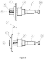
- Figure 3 shows side views of schematic illustrations of parts of the winch 100 in different operating states according to some example implementations as described herein.
- the drum plate 6 is moved to be close to the slide holder 8 of the drum-moving device 4.
- the drum plate 6 may be moved away from the slide holder 8 by a distance L.
- the screw 12 is in a fixed position in a direction generally parallel to the axis of rotation of the drum 2. It is, in this example, merely the drum plate 6 (or generally the drum 2) which moves forth and back in the direction as indicated in Figure 3 , i.e. the direction generally parallel to the axis of rotation of the drum 2.
- the two images in Figure 3 relate to the drum 2 being in a wound and an unwound state, respectively.
- the rope 3 may be maintained in a straight path between the drum 2 and the wheel 15.
- the hollow gearbox shaft 11 allows for the screw 12 to be arranged partially within the gearbox shaft 11 (or in some example implementations to completely penetrate the gearbox shaft 11), such that a particularly compact and stable design of the winch 100 may be provided.
Landscapes
- Engineering & Computer Science (AREA)
- Mechanical Engineering (AREA)
- Transmission Devices (AREA)
Priority Applications (1)
| Application Number | Priority Date | Filing Date | Title |
|---|---|---|---|
| EP17197438.9A EP3473584A1 (fr) | 2017-10-20 | 2017-10-20 | Treuil |
Applications Claiming Priority (1)
| Application Number | Priority Date | Filing Date | Title |
|---|---|---|---|
| EP17197438.9A EP3473584A1 (fr) | 2017-10-20 | 2017-10-20 | Treuil |
Publications (1)
| Publication Number | Publication Date |
|---|---|
| EP3473584A1 true EP3473584A1 (fr) | 2019-04-24 |
Family
ID=60153152
Family Applications (1)
| Application Number | Title | Priority Date | Filing Date |
|---|---|---|---|
| EP17197438.9A Withdrawn EP3473584A1 (fr) | 2017-10-20 | 2017-10-20 | Treuil |
Country Status (1)
| Country | Link |
|---|---|
| EP (1) | EP3473584A1 (fr) |
Citations (4)
| Publication number | Priority date | Publication date | Assignee | Title |
|---|---|---|---|---|
| JPS4870671U (fr) * | 1971-12-09 | 1973-09-06 | ||
| JPS49133357U (fr) * | 1973-03-15 | 1974-11-15 | ||
| US6520485B1 (en) | 2000-10-13 | 2003-02-18 | Olaf Soot | Winch system for raising and lowering theatre scenery |
| CN106986277A (zh) * | 2017-05-04 | 2017-07-28 | 中国石油大学(华东) | 一种具有自动排绳及测力功能的柔索驱动装置及方法 |
-
2017
- 2017-10-20 EP EP17197438.9A patent/EP3473584A1/fr not_active Withdrawn
Patent Citations (4)
| Publication number | Priority date | Publication date | Assignee | Title |
|---|---|---|---|---|
| JPS4870671U (fr) * | 1971-12-09 | 1973-09-06 | ||
| JPS49133357U (fr) * | 1973-03-15 | 1974-11-15 | ||
| US6520485B1 (en) | 2000-10-13 | 2003-02-18 | Olaf Soot | Winch system for raising and lowering theatre scenery |
| CN106986277A (zh) * | 2017-05-04 | 2017-07-28 | 中国石油大学(华东) | 一种具有自动排绳及测力功能的柔索驱动装置及方法 |
Similar Documents
| Publication | Publication Date | Title |
|---|---|---|
| CN103626062B (zh) | 基于特殊缆绳的大容绳量储缆绞车 | |
| WO2022247402A1 (fr) | Appareil de pose et d'enroulement de câble automatique à source de puissance unique réglable | |
| CA2876228C (fr) | Treuil et procede d'utilisation du treuil | |
| CN202575796U (zh) | 深水绞车 | |
| US9962621B2 (en) | Compact hoist system | |
| US20170226794A1 (en) | Driving device for window blind | |
| US6921060B2 (en) | Winch handle | |
| JP2017128445A (ja) | 引張ストランドを有するウインチ | |
| US3801813A (en) | Combination mast and light raising and lowering apparatus | |
| EP3473584A1 (fr) | Treuil | |
| CN105947812B (zh) | 一种船舶用线缆卷绕架 | |
| US11932522B2 (en) | Rope guiding device of rope hoist | |
| US6776397B2 (en) | Convertible winch | |
| CN110240020B (zh) | 可伸缩绞缆机 | |
| KR20110038745A (ko) | 블라인드의 승강조작장치 | |
| CN110498304B (zh) | 光纤光缆收放装置 | |
| CN210763750U (zh) | 一种弹簧动力的防水电缆卷盘 | |
| CN220245397U (zh) | 巡检机器人及其单向动力驱动的升降装置 | |
| CN205998783U (zh) | 一种船舶用线缆卷绕架 | |
| KR200477188Y1 (ko) | 안전장치를 구비한 차광 및 비가림막 | |
| CN115680464A (zh) | 一种免打孔安装机构及窗帘 | |
| CN214653236U (zh) | 一种舞台用三维一体式吊机 | |
| US20180093870A1 (en) | Winch Fairlead Pivot | |
| CN220412723U (zh) | 一种船舶甲板用自动缠绕式船用绞车 | |
| CN112109882A (zh) | 一种电力巡检无人机脚架收放装置 |
Legal Events
| Date | Code | Title | Description |
|---|---|---|---|
| PUAI | Public reference made under article 153(3) epc to a published international application that has entered the european phase |
Free format text: ORIGINAL CODE: 0009012 |
|
| AK | Designated contracting states |
Kind code of ref document: A1 Designated state(s): AL AT BE BG CH CY CZ DE DK EE ES FI FR GB GR HR HU IE IS IT LI LT LU LV MC MK MT NL NO PL PT RO RS SE SI SK SM TR |
|
| AX | Request for extension of the european patent |
Extension state: BA ME |
|
| 17P | Request for examination filed |
Effective date: 20191021 |
|
| RBV | Designated contracting states (corrected) |
Designated state(s): AL AT BE BG CH CY CZ DE DK EE ES FI FR GB GR HR HU IE IS IT LI LT LU LV MC MK MT NL NO PL PT RO RS SE SI SK SM TR |
|
| 17Q | First examination report despatched |
Effective date: 20200312 |
|
| STAA | Information on the status of an ep patent application or granted ep patent |
Free format text: STATUS: THE APPLICATION HAS BEEN WITHDRAWN |
|
| 18W | Application withdrawn |
Effective date: 20200514 |