EP3474227A1 - Procédé, produit de programme informatique et système informatique pour corriger une image ct - Google Patents
Procédé, produit de programme informatique et système informatique pour corriger une image ct Download PDFInfo
- Publication number
- EP3474227A1 EP3474227A1 EP17197663.2A EP17197663A EP3474227A1 EP 3474227 A1 EP3474227 A1 EP 3474227A1 EP 17197663 A EP17197663 A EP 17197663A EP 3474227 A1 EP3474227 A1 EP 3474227A1
- Authority
- EP
- European Patent Office
- Prior art keywords
- image
- value
- cbct
- values
- voxels
- Prior art date
- Legal status (The legal status is an assumption and is not a legal conclusion. Google has not performed a legal analysis and makes no representation as to the accuracy of the status listed.)
- Granted
Links
Images




Classifications
-
- G—PHYSICS
- G06—COMPUTING OR CALCULATING; COUNTING
- G06T—IMAGE DATA PROCESSING OR GENERATION, IN GENERAL
- G06T12/00—Tomographic reconstruction from projections
- G06T12/30—Image post-processing, e.g. metal artefact correction
-
- G—PHYSICS
- G06—COMPUTING OR CALCULATING; COUNTING
- G06T—IMAGE DATA PROCESSING OR GENERATION, IN GENERAL
- G06T5/00—Image enhancement or restoration
- G06T5/50—Image enhancement or restoration using two or more images, e.g. averaging or subtraction
-
- A—HUMAN NECESSITIES
- A61—MEDICAL OR VETERINARY SCIENCE; HYGIENE
- A61B—DIAGNOSIS; SURGERY; IDENTIFICATION
- A61B6/00—Apparatus or devices for radiation diagnosis; Apparatus or devices for radiation diagnosis combined with radiation therapy equipment
- A61B6/02—Arrangements for diagnosis sequentially in different planes; Stereoscopic radiation diagnosis
- A61B6/03—Computed tomography [CT]
- A61B6/032—Transmission computed tomography [CT]
-
- A—HUMAN NECESSITIES
- A61—MEDICAL OR VETERINARY SCIENCE; HYGIENE
- A61B—DIAGNOSIS; SURGERY; IDENTIFICATION
- A61B6/00—Apparatus or devices for radiation diagnosis; Apparatus or devices for radiation diagnosis combined with radiation therapy equipment
- A61B6/40—Arrangements for generating radiation specially adapted for radiation diagnosis
- A61B6/4064—Arrangements for generating radiation specially adapted for radiation diagnosis specially adapted for producing a particular type of beam
- A61B6/4085—Cone-beams
-
- A—HUMAN NECESSITIES
- A61—MEDICAL OR VETERINARY SCIENCE; HYGIENE
- A61N—ELECTROTHERAPY; MAGNETOTHERAPY; RADIATION THERAPY; ULTRASOUND THERAPY
- A61N5/00—Radiation therapy
- A61N5/10—X-ray therapy; Gamma-ray therapy; Particle-irradiation therapy
- A61N5/103—Treatment planning systems
- A61N5/1039—Treatment planning systems using functional images, e.g. PET or MRI
-
- G—PHYSICS
- G06—COMPUTING OR CALCULATING; COUNTING
- G06F—ELECTRIC DIGITAL DATA PROCESSING
- G06F16/00—Information retrieval; Database structures therefor; File system structures therefor
- G06F16/50—Information retrieval; Database structures therefor; File system structures therefor of still image data
- G06F16/53—Querying
-
- G—PHYSICS
- G06—COMPUTING OR CALCULATING; COUNTING
- G06T—IMAGE DATA PROCESSING OR GENERATION, IN GENERAL
- G06T5/00—Image enhancement or restoration
- G06T5/40—Image enhancement or restoration using histogram techniques
-
- G—PHYSICS
- G06—COMPUTING OR CALCULATING; COUNTING
- G06T—IMAGE DATA PROCESSING OR GENERATION, IN GENERAL
- G06T5/00—Image enhancement or restoration
- G06T5/90—Dynamic range modification of images or parts thereof
- G06T5/92—Dynamic range modification of images or parts thereof based on global image properties
-
- G—PHYSICS
- G06—COMPUTING OR CALCULATING; COUNTING
- G06T—IMAGE DATA PROCESSING OR GENERATION, IN GENERAL
- G06T7/00—Image analysis
- G06T7/0002—Inspection of images, e.g. flaw detection
- G06T7/0012—Biomedical image inspection
- G06T7/0014—Biomedical image inspection using an image reference approach
-
- G—PHYSICS
- G16—INFORMATION AND COMMUNICATION TECHNOLOGY [ICT] SPECIALLY ADAPTED FOR SPECIFIC APPLICATION FIELDS
- G16H—HEALTHCARE INFORMATICS, i.e. INFORMATION AND COMMUNICATION TECHNOLOGY [ICT] SPECIALLY ADAPTED FOR THE HANDLING OR PROCESSING OF MEDICAL OR HEALTHCARE DATA
- G16H20/00—ICT specially adapted for therapies or health-improving plans, e.g. for handling prescriptions, for steering therapy or for monitoring patient compliance
- G16H20/40—ICT specially adapted for therapies or health-improving plans, e.g. for handling prescriptions, for steering therapy or for monitoring patient compliance relating to mechanical, radiation or invasive therapies, e.g. surgery, laser therapy, dialysis or acupuncture
-
- G—PHYSICS
- G16—INFORMATION AND COMMUNICATION TECHNOLOGY [ICT] SPECIALLY ADAPTED FOR SPECIFIC APPLICATION FIELDS
- G16H—HEALTHCARE INFORMATICS, i.e. INFORMATION AND COMMUNICATION TECHNOLOGY [ICT] SPECIALLY ADAPTED FOR THE HANDLING OR PROCESSING OF MEDICAL OR HEALTHCARE DATA
- G16H30/00—ICT specially adapted for the handling or processing of medical images
- G16H30/40—ICT specially adapted for the handling or processing of medical images for processing medical images, e.g. editing
-
- G—PHYSICS
- G16—INFORMATION AND COMMUNICATION TECHNOLOGY [ICT] SPECIALLY ADAPTED FOR SPECIFIC APPLICATION FIELDS
- G16H—HEALTHCARE INFORMATICS, i.e. INFORMATION AND COMMUNICATION TECHNOLOGY [ICT] SPECIALLY ADAPTED FOR THE HANDLING OR PROCESSING OF MEDICAL OR HEALTHCARE DATA
- G16H50/00—ICT specially adapted for medical diagnosis, medical simulation or medical data mining; ICT specially adapted for detecting, monitoring or modelling epidemics or pandemics
- G16H50/70—ICT specially adapted for medical diagnosis, medical simulation or medical data mining; ICT specially adapted for detecting, monitoring or modelling epidemics or pandemics for mining of medical data, e.g. analysing previous cases of other patients
-
- G—PHYSICS
- G06—COMPUTING OR CALCULATING; COUNTING
- G06T—IMAGE DATA PROCESSING OR GENERATION, IN GENERAL
- G06T2207/00—Indexing scheme for image analysis or image enhancement
- G06T2207/10—Image acquisition modality
- G06T2207/10072—Tomographic images
- G06T2207/10081—Computed x-ray tomography [CT]
-
- G—PHYSICS
- G06—COMPUTING OR CALCULATING; COUNTING
- G06T—IMAGE DATA PROCESSING OR GENERATION, IN GENERAL
- G06T2207/00—Indexing scheme for image analysis or image enhancement
- G06T2207/20—Special algorithmic details
- G06T2207/20212—Image combination
- G06T2207/20224—Image subtraction
-
- G—PHYSICS
- G06—COMPUTING OR CALCULATING; COUNTING
- G06T—IMAGE DATA PROCESSING OR GENERATION, IN GENERAL
- G06T2207/00—Indexing scheme for image analysis or image enhancement
- G06T2207/30—Subject of image; Context of image processing
- G06T2207/30004—Biomedical image processing
- G06T2207/30008—Bone
-
- G—PHYSICS
- G06—COMPUTING OR CALCULATING; COUNTING
- G06T—IMAGE DATA PROCESSING OR GENERATION, IN GENERAL
- G06T2210/00—Indexing scheme for image generation or computer graphics
- G06T2210/41—Medical
-
- G—PHYSICS
- G06—COMPUTING OR CALCULATING; COUNTING
- G06T—IMAGE DATA PROCESSING OR GENERATION, IN GENERAL
- G06T2211/00—Image generation
- G06T2211/40—Computed tomography
- G06T2211/424—Iterative
Definitions
- the present invention relates to methods for improving adaptive radiotherapy as well as computer program products and a computer system in which such methods may be implemented.
- the treatment is given in a number of sessions, called fractions.
- the treatment plan to be used is generated, based on high-resolution images which are typically CT images.
- a new image typically a cone beam CT (CBCT) image
- CBCT cone beam CT
- These images can also be used in adaptive radiotherapy, wherein the images are used to calculate the actually delivered dose (given the up to date patient information).
- the CBCT images are registered (preferably deformably) with the planning CT.
- CBCT images typically have pronounced artefacts, which introduce errors in the calculated dose. These artefacts thus have to be corrected for if an accurate dose is to be found based on these images.
- CT image in this document can be taken to mean any type of CT image, including conventional CT images, helical CT images, and CBCT images.
- the planning CT image and subsequent CBCT images will differ, when comparing them through a registration, for three main reasons: anatomical differences, registration errors and image artefacts.
- Image artefacts are primarily present in the CBCT.
- shading artefacts result in that the same tissue type is given varying values depending on its spatial location in the image.
- differences caused by shading artefacts should be handled, since they produce relatively large dose computation errors.
- Differences caused by actual anatomical differences (e.g. mismatching air cavities or misaligned bone) or deformation errors should be ignored when using the planning CT to correct the CBCT. Therefore, it is important to differentiate between the three kinds of differences.
- Pengwei Wu et al., Iterative CT shading correction with no prior information, Phys. Med. Biol., 60 (2015) 8437-8455 proposes a method of eliminating artefacts in any type of CT image, including CBCT, using a template generated from the image based on general knowledge about typical value range in a CT image.
- the CT image is segmented and corrected, using the template as a reference.
- This method requires a segmentation algorithm and the quality of the segmentation directly influences the output quality. Further, the method is dependent on a good approximation of what tissues the patient consists of.
- the invention relates to a method of correcting a first CT image for artefacts, using a second CT image as a template, while maintaining the anatomical information in the first CT image.
- the CT images may be any types of CT images.
- the image used as a template will be of a higher quality than the image being corrected.
- the first CT image may be a CBCT image and the second CT image may be a conventional, or helical CT image.
- the method is based on the insight that the shading artefacts typically vary with a low spatial frequency while the differences caused by displacement or geometrical changes normally vary with a higher spatial frequency.
- the conversion method according to the second aspect is particularly suitable.
- a suitable conversion method is proposed. This method may also be used for other purposes.
- the invention relates to a method of correcting a first CT image for artefacts, comprising the steps of
- the influence from artefacts, which occur in lower quality images such as CBCT images will be reduced.
- other differences between the images caused by anatomical changes or registration errors, which often give small shifts between corresponding structures in the two images, will be identified so that the correction will not compensate for such differences but only the differences that are actually due to artefacts.
- a CBCT image that is suitable for dose computation in radiotherapy planning by using a planning CT image taken earlier as reference.
- a planning CT image will be a conventional or helical CT image.
- the original first and second CT images are typically unmodified images and the first image is assumed to need corrections because of artefacts. Normally the procedure includes storing these images for use later in the procedure. If the images do not use the same value range, the step of ensuring that the images use the same value range comprises converting one of the images to the value range used in the other image.
- the second CT image may be converted to the value range of the first CT image, so that the value matched image pair comprises the values of the first CT image and of a transformed second CT image tCT.
- the first CT image may be converted to the value range of the second CT image, so that the value matched image pair comprises values of the second CT image and of the transformed first CT image tCBCT.
- the current first CT image may be formed iteratively by applying correction maps to an image that is updated stepwise by each correction map.
- the current first CT image may be formed by applying a sum of several correction maps, or the current information stored in the final correction map, to the original first CT image.
- the conversion if necessary, is typically performed by means of a transformation representation such as a function, a lookup table (LUT) or a diagram, said transform representation mapping a value in the first CT image to a value in the second CT image or vice versa, and applying that transformation representation to the image that is to be converted.
- a transformation representation such as a function, a lookup table (LUT) or a diagram
- LUT lookup table
- a new conversion between the first CT image and second CT image may be performed after the updating of the first CT image. This may be advantageous since the first CT image has then been improved, which will result in a better transformation result.
- the second CT image which is used as a reference, is based on Hounsfield units, since this is the value scale used in most CT images.
- a deformable registration method is used, since this will produce a more correct result.
- a rigid registration may also be used.
- the image mask is defined so that it includes voxels for which the corresponding voxels in the difference image contain information about the artefacts to be corrected for, whilst excluding voxels containing information irrelevant to the correction.
- the image mask may include voxels for which the difference is below a threshold value and excludes voxels for which the difference is above the threshold value
- a suitable sequence of steps for producing the image mask has been found to be Steps i, iv, possibly iterated one or more of times Steps i, iii, iv, v, vi possibly iterated one or more of times Steps i and iv, possibly iterated one or more times Steps i, iii, iv, v, vi.
- a suitable sequence of steps for finding the correction map C has been found to be:
- the second aspect of the invention relates to a method of creating a transformation representation which may be used for converting a first CT image by a method including registration with a corresponding, second CT image, for example, a planning CT image, which is normally of higher quality and based on values enabling dose computations, that is, values reflecting the densities or electron densities.
- a method according to this second aspect is a method of creating a representation of a transformation between a first CT image of an object and a second CT image of the object, said first CT image using a first CT value range and said second CT image using a second CT value range different from the first CT value range, said method comprising
- Either the first or the second CT image may be a CBCT image and the other CT image may be a conventional or helical CT.
- the method comprises the steps of creating a CT histogram of the occurrences of values in one of the images and, based on the occurrences, selecting the number of tissue value pairs to be found in step c) and optionally restricting the area in the joint histogram for step c).
- the voxels to be used in step c) are preferably selected as voxels having a value below a set threshold, preferably corresponding to the density of bone tissue.
- a line is identified for values above the threshold, for example using the RANSAC method.
- a particularly good result is achieved if the step of identifying the line comprises forcing the line to pass through the point corresponding to the tissue value pair with the highest density below the bone density threshold.
- tissue value pairs may refer to any value pair designating the same material, not only tissue, for example air, water or phantom material.
- the data representing the registration is preferably based on a deformable registration of the images but it may also be based on a rigid registration.
- the first CT image may be converted, fully automatically, to an image on which dose computations may be performed, while keeping the geometry as in the first CT image.
- Fully automatic in this context means that no manual interaction or segmentation of the images used will be necessary.
- the method is particularly suitable for converting CBCT images, which are often used to provide updated information during adaptive treatment, to a value range that may be used for dose computation.
- the converted CBCT image can be more easily compared to the CT image.
- a conversion from CT to CBCT can also, or alternatively, be obtained, or between any two images of the same object, or region of a patient.
- the invention also relates to a computer program product comprising computer readable code means which when run in a processor will cause the processor to perform any one of the methods disclosed above.
- the computer program product may be stored on any suitable storage means such as a non-transitory storage means.
- the invention also relates to a computer system comprising a processing means, at least one program memory holding at least one computer program as outlined above and at least one data memory holding data to be used in the method.
- Figure 1a shows a CT image that may be used in aspects of the present invention.
- the CT image is obtained before treatment and used in treatment planning.
- the CT image shows the attenuation coefficient of the tissue in each voxel as Hounsfield Units (HU).
- the attenuation coefficient is related to density.
- density or electron density, or any suitable scale that is related to one of them, may be used instead of Hounsfield Units.
- CBCT CBCT
- CT computed tomography
- the image to be converted and/or corrected has a lower quality, for example more shading artefacts, than the image used as reference in the correction and/or conversion.
- Figure 1b shows a CBCT image of the same region of the same patient, that has been converted to the same scale as the CT image.
- Figures 1a and 1b have normally been taken at different times so that there will probably be anatomical differences between them.
- a CBCT image is taken before each of the treatment fractions.
- the CBCT image uses a different scale for voxel values that does not match the HU scale, so that conversion is needed to enable comparison of the CT image and the CBCT image.
- the CBCT image may have been obtained on a scale similar to the HU scale, in which case conversion will not be necessary.
- Figures 1a and 1b show substantially the same geometry, but the CBCT image includes shading artefacts which will lead to inaccuracy in the dose computation. There are also minor differences caused by anatomical changes and/or slightly different positioning of the patient.
- Figure 1c is a new version of the CBCT image of Figure 1b , corrected according to the process of Figure 2 to be suitable for dose computations.
- the corrected CBCT image has the same geometry as the CBCT image of Figure 1b , but is more similar to the CT image of Figure 1a when it comes to voxel values, since artefacts have been reduced.
- Figure 1d shows a difference image after deformable registration, reflecting the value difference between each voxel in the CBCT image shown in Figure 1b and the corresponding voxel in the CT image.
- difference image as indicated by the scale to the right of the image, voxels that are similar in value between the images are shown in a grey colour. Differences are shown as increasingly bright colours for values that are lower in the CBCT image than in the CT image and increasingly dark colour, for values that are higher in the CBCT image than in the CT image. A higher colour difference from the centre grey colour marked with 0 indicates a greater difference in values. As can be seen, a significant portion of the image is either near white or near black, which indicates a large difference between the CT image and the CBCT image.
- Figure 1e shows a new difference image, created in the same way as Figure 1d , but showing the difference between the CT image and the corrected CBCT image shown in Figure 1c .
- the new difference image is grey over the majority of the image, indicating that the differences between corresponding voxels in the CT image and the corrected CBCT image are generally small.
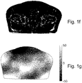
- Figure 1f is a mask used to select which voxels are to be taken into account in the correction.
- the white areas in the mask belong to voxels where the difference in voxel values are mainly due to anatomical differences and are thus not taken into account in the correction.
- the image mask is based on the difference image and may also include information from the tCT and CBCT and possibly from a correction map obtained earlier. How to obtain and use the mask will be discussed below.
- Figure 1g is a correction map based on the mask of Figure 1f , which may be obtained as discussed in connection with Figure 3 .
- the correction map indicates, by means of a grey scale, which areas of the CBCT image should be corrected and by how much. As indicated by the scale next to the image, a black or white region indicates that a large correction in the negative or positive direction, respectively, is necessary. The closer a region is to the colour matching the value 0 on the scale, the smaller correction is needed in that region.
- the process of creating a correction map based on the difference image is based on a filtering method involving identifying the areas in the difference image for which the difference between the CT value and the CBCT value is caused by artefacts.
- This method effectively blurs a masked difference image only containing differences due to artefacts to effectively eliminate the remaining high spatial frequency changes, for example noise and anatomical changes not excluded by the mask.
- the changes that are due to low frequency artefacts are preserved and will be included in the correction map.
- the CBCT image is corrected using a correction map which is computed in each iteration. For each iteration, more and more of the low frequency artefacts will be removed and the values of the difference image will be closer and closer to zero.
- the resulting correction map is applied to the original CBCT image ( Fig. 1b ) to obtain the resulting CBCT image ( Fig. 1d ).
- Figure 2 is a flow chart of a method of obtaining a corrected CBCT image that is suitable for use in dose planning.
- the method is also suitable for correcting other types of CT images, typically CT images of a lower quality than the ones used as reference in the correction.
- a CT image and a CBCT image of the same region of a patient are provided and registered, preferably deformably.
- the registration facilitates voxel-wise comparison and the creation of difference images.
- the CT image was obtained before the start of the treatment and used for treatment planning whereas the CBCT images are normally obtained before each treatment fraction.
- the CT image normally has a known HU to density relationship whereas this is often not the case for CBCT images.
- the values typically vary in the same direction, that is, the same tissue types will have higher values, or lower values, respectively, in the two images.
- the registration may have been performed in advance, in which case the registration data can be obtained and no registration has to be performed in this step. If a rigid registration was performed, the registration data will normally define a displacement and a rotation between the images. If a deformable registration was performed, the registration data will comprise a vector field defining the displacement of each voxel.
- step S22 a value transformation, facilitating a conversion between the CT and CBCT images, is obtained. If the image value ranges are sufficiently similar, this step may be skipped.
- the value transformation may for example be in the form of a lookup table matching values in the CT and CBCT images to each other. This may be done in any suitable manner. A particularly suitable way of creating the transformation is described in Figure 4 .
- step S23 the CT image is transformed to an image denoted, tCT, by converting the values of the CT image to the corresponding CBCT values, using the transformation obtained in step S22.
- the two images must use corresponding value ranges, but which one to choose may be selected depending on the desired result.
- the CBCT image could be transformed to a transformed CBCT image tCBCT using the corresponding CT values.
- an initial image mask M M(D) is defined, to select which voxels are to be included in the correction.
- the image mask is based on the difference image and may also include information from the tCT and CBCT.
- M should include voxels containing differences that are due to CBCT shading artefacts but exclude voxels with differences caused by anatomical differences or deformation errors. In one embodiment, this is achieved by applying a threshold to D, so that voxels having a difference value smaller than the threshold are included in the mask and voxels having a greater difference value are disregarded.
- segmentations of the two images may be used to identify voxels which belongs to the same segmented class. Voxels that belong to the same segmented class may be included, while voxels not belonging to the same class are disregarded.
- step S26 an iterative procedure is performed to obtain a final correction map Cf.
- An embodiment of this procedure is discussed in connection with Figure 3 .
- the correction map can be applied directly to the CBCT image to produce the corrected CBCT image, as described above. If, in step S23, the CBCT image was converted, the correction map can be applied directly to the converted CBCT image to produce a converted, corrected CBCT image where the voxel values are according to the HU scale or have a defined relationship to the HU scale. Alternatively, in the latter case, the correction map may be converted to CBCT values and applied to the original CBCT image.
- step S28 a final value transformation is calculated based on the corrected CBCT image. This final value transformation is applied to the corrected CBCT image.
- FIG. 3 is a more detailed disclosure of an embodiment of the iterative procedure of step S26. Not all of the steps need to be performed in each iteration, as will be discussed below. Therefore, in a first step S31, input is taken from step S25, and it is determined which steps are to be run in the next iterations. The criteria for selecting steps will be discussed below.
- a correction map C is found by smoothing the masked difference image, that is, the difference image where voxels not included in the mask are disregarded. This is performed by any suitable method for smoothing the values and preferably also inserting suitable values where the mask does not include information on differences. This removes noise and sharp edges found in the difference image D and also fills in the areas not included in the mask M.
- This mask is originally obtained in step S25 but may be repeatedly updated in step S35 so in subsequent iterations of the procedure of Figure 3 the latest updated mask is used.
- the final correction map is the one that will be used in step S27. As will be understood this value is obtained through a number of iterations of Figure 3 .
- step S34 the CBCT image is updated using the correction map C, that is, the current CBCT is set to be CBCT + C.
- the voxels in which the current correction will bring the difference below a certain threshold T are included by the mask, that is, voxels for which ABS(D - C) ⁇ T. It would also be possible to apply more complex decision criteria, for example based on the tCT and/or CBCT images.
- step S36 the value transformation is updated based on the current CBCT image, and the tCT is updated based on the updated value transformation. Of course, this only has to be done if the CBCT image has changed.
- Step S38 is a decision step to determine if the process of Figure 3 should be repeated. If no, the procedure proceeds to step S27. If yes, the procedure returns to step S31, taking input values from the most recent iteration of the flow of Figure 3 . For example, the loop may terminate after a maximum number of iterations. Alternatively, convergence between the CT image and the CBCT image may be used as a criterion.
- step S31 of which steps to run in the current iteration may be made based on different types of criteria.
- a predetermined order of iterations could be set up, specifying which steps are to be performed in each iteration.
- One possible such setup, for first defining the mask and then the correction map, would be
- a series of sequences i. - iv. are run to determine the mask M.
- the CBCT values are reset to the original CBCT values in step v, and the last iterations, step vi, are run to determine the final correction map Cf that is to be applied to the CBCT image.
- the sequences, and the numbers of iterations are merely examples and may be set in any way that is seen fit.
- the number of iterations of each sequence will preferably be determined by convergence criteria, that is, how well the resulting mask, or the correction map, matches the desired result.
- the converted CBCT image may be obtained in any suitable way.
- the CBCT image will already have values that are similar to the HU values used in the CT, in which case no conversion will be needed.
- the image that is here referred to as CBCT may instead be an image of another CT modality, which uses values similar to that of the CT image used for correction.
- a method of converting a CBCT image is disclosed in the following, with reference to Figure 4 .
- This method is suitable for use in the context of the method of Figure 2 but can also be used in any context, for other purposes where a converted CBCT image is needed.
- a common way of converting the CBCT image is to create a value transformation, for example in the form of a lookup table (LUT) mapping values in the CBCT image to values in corresponding voxels of the CT image. Such a value transformation may be obtained in different ways.
- LUT lookup table
- Figure 4 discloses a method of obtaining a representation that may be used to perform a transformation from CBCT values to CT values, or vice versa.
- the representation may be presented in the form of a function, a lookup table, a diagram or in any other suitable way.
- step S41 the CT image and the CBCT image are provided.
- the CT image has been obtained at an earlier stage, while the CBCT image is a more recent image.
- step S42 the CT image and the CBCT image are registered, preferably using a deformable registration method. This will allow a point-wise mapping of the two images. As in Step S21, the registration may have been performed earlier, in which case registration data are provided instead.
- a joint histogram is created based on the CT image, the CBCT image and the registration data.
- the registration data are used to match the value of each voxel of the CT image, with the corresponding value in the CBCT image to create value pairs.
- the number of occurrences of each value pair is stored in the joint histogram.
- a simplified example of such a joint histogram is shown in Figure 5b .
- the joint histogram is used to find a set of tissue value pairs to be used in the transform between the CT image and the CBCT image or vice versa.
- the joint histogram is smoothed by a suitable algorithm to remove noise.
- Step S44 is an optional step, in which the number of tissue value pairs, and/or the actual values to be found in step S45 is decided. Further, for each of these tissue value pairs a restricted area in the joint histogram may be found. This may be done randomly, but is preferably based on a histogram showing the number of occurrences of the values of the CT image or of the CBCT image. The peak values in such a histogram correspond to different types of tissue in the image. The number of peaks, as well as the positions of the valleys between them, may be used to determine the number of tissue value pairs to be found or value restrictions that should be used. An example of such a histogram is shown in Figure 5a .
- tissue value pairs must be selected in such a way that they have a certain minimum distance between them. It would be possible at this stage also to select the values of the CT image that are to be matched with CBCT values to create value pairs. Typically, however, the CT values and the CBCT values are both identified in the joint histogram, as described in step S45.
- tissue value pairs are identified, to be used for creating the transform representation, where appropriate in accordance with step S44.
- the tissue value pairs may be identified in any suitable way, but preferably based on the joint histogram.
- the tissue value pairs should be selected among the most frequently occurring value pairs in at least one of the images, which may be identified, for example, by finding peaks in the joint histogram. If step S44 is performed, the value pairs are identified in accordance with the information obtained in step S44, determining the number of tissue value pairs and their respective value range restrictions. It is feasible, but not necessary, to search for value pairs in restricted areas typically starting in one peak area and moving on to one or more other areas.
- These restricted areas can be determined in any suitable way, for example, based on their distances from previously found tissue value pairs and/or information obtained in step S44.
- the order in which the tissue value pairs are found is not crucial but may suitably be decided based on the peak size determined in step S44.
- the peaks can be handled in any suitable order, for example working from left to right in the diagram.
- One particularly feasible way would be to start searching for the tissue value pair corresponding to the largest peak in step S44, which would assure that the most common tissue type will be regarded first and thus cannot be excluded based on restrictions set by earlier found tissue value pairs. Then the next largest peak would be considered, and so on. It would also be possible, to set restrictions on following tissue value pairs that ensure that the transformation representation will be monotonically increasing.
- the value pairs may be selected as the maximum positions in the CT and CBCT histograms created from the joint histogram, or part of the joint histogram, by collapsing it in one or the other direction.
- a certain density threshold corresponding to bone
- Step S46 is an optional step in which a line or a match for bone tissues are identified.
- the values for bone tissues will be in the upper right part of the joint histogram.
- the match for bone tissues may be obtained in any suitable way, for example by linear regression or by using the RANSAC method.
- the RANSAC method finds the line that maximizes the number of data points within a certain distance from the line.
- the line may be forced to connect to any previously found tissue value pair.
- a number of points from this line are saved as tissue value pairs indicating bone tissues. This step could be performed at any suitable stage of the procedure.
- This method is based on the assumption that while there will probably be some mismatches between the tissue types in the CT and CBCT images, most of the apparent overlaps will probably be correct, meaning that if a region in one image appears to be the same type of tissue as a corresponding region in the other image, this will probably be correct for a majority of the voxels in the region. Hence, the value pairs that occur most frequently in the joint histogram will correctly match the values in the CBCT image to the values in the CT image.
- step S47 interpolation is performed between the tissue value pairs generated in steps S45 and optionally S46, to create a representation of the transform between the CT image and the CBCT image, or vice versa.
- the representation may be in any suitable form, such as a function, a lookup table (LUT) or a diagram. Such a diagram is shown in Figure 5c as a continuous line relating each value in the CT image to the corresponding value in the CBCT image.
- the representation may be adapted to a straight line, or to straight lines between the tissue value pairs generated in step S45, which may have different inclinations, or may have any other suitable shape.
- the representation can also incorporate information on tissue distribution width in the joint histogram, as shown in Figure 5b , for example, to shape the transformation into plateaus around these areas, as exemplified in Figure 5d .
- a reversed transformation can be created for going from CT values to CBCT values, for use in the method of Figure 2 .
- step S48 the values in the CBCT image are transformed to the corresponding values from the CT image, or vice versa, using the representation obtained in step S47.
- the transformation may be performed at any suitable time after the representation has been made available.
- tissue value pairs in step S45 when identifying the tissue value pairs in step S45, prominent peaks in the joint histogram, that is, frequently occurring value pairs, can be identified.
- a peak When a peak has been identified and selected as a tissue value pair, it may be suitable to discard any peaks close to the selected peak from further consideration. In any such case, the highest peak among the adjacent peaks should be selected.
- value pairs that occur infrequently, and/or low regions in the histogram of CT values should be actively avoided.
- Figure 5a shows, schematically, what a histogram such as the one referred to in Step S44 could look like.
- the horizontal axis represents the HU values and the vertical axis represents the number of voxels having each particular HU value.
- the curve there will typically be some peaks corresponding to the most common types of tissue in the image and some low areas for which there are no or few voxels.
- Figure 5b shows a simplified joint histogram as obtained in step S43, with CBCT values along the horizontal axis and CT values along the vertical axis.
- the shaded areas correspond to value pairs indicative of different tissue types.
- the leftmost, lowermost shaded area corresponds to air, which has the lowest density values in both images.
- a wider range of CBCT values will be matched to a narrower range of CT values, resulting in somewhat oblong shaded areas in the diagram.
- the shaded area corresponding to the highest values represents bone tissue.
- Figure 5c shows a resulting transformation, illustrated as a diagram in which lines have been inserted to join the shaded areas for Figure 5b together to approximate matches between CBCT and CT values along the whole value range of the image.
- Figure 5d shows an alternative diagram to the one shown in Figure 5c .
- the curve has two plateaus, where each CT value is matched to a range of CBCT values. This reflects the common situation where a broad range of CBCT values corresponds to a narrower range of CT values.
- To obtain the CT value corresponding to any given CBCT value simply find the point on the curve corresponding to the CBCT value along the horizontal axis and determine the matching CT value on the vertical axis, as illustrated by the dotted lines in Figure 5d .
- a table or diagram creating a mapping in the opposite direction, that is enabling the CBCT value corresponding to a given CT value may also be useful. Values may be represented in any suitable way in the table and/or diagram.
- FIG. 6 is a schematic drawing of a computer system in which the method according to the invention may be performed.
- a computer 31 comprises a processor 33, a first and a second data memory 34, 35 and a first and a second program memory 36, 37.
- one or more user input means 38, 39 are also present, in the form of a keyboard, a mouse, a joystick, voice recognition means or any other available user input means.
- the user input means may also be arranged to receive data from an external memory unit.
- the first data memory 34 comprises at least one CT image and at least one corresponding CBCT image.
- the second data memory 35 holds data related obtained during the procedure, including the correction map and the mask.
- the first program memory 36 holds a computer program arranged to make the computer perform the method steps discussed in connection with Figures 2 and 3 .
- the second program memory 37 holds a computer program arranged to make the computer perform the method steps discussed in connection with Figure 4 .
- the data memories 34, 35 and the program memories 36, 37 are shown and discussed schematically. There may be several data memory units, each holding one or more different types of data, or one data memory holding all data in a suitably structured way, and the same holds for the program memories. For example, there may be separate memories or memory segments for different image modalities. One or more memories may also be stored on other computers.
Landscapes
- Engineering & Computer Science (AREA)
- Health & Medical Sciences (AREA)
- Medical Informatics (AREA)
- Theoretical Computer Science (AREA)
- Physics & Mathematics (AREA)
- General Health & Medical Sciences (AREA)
- Life Sciences & Earth Sciences (AREA)
- Public Health (AREA)
- Nuclear Medicine, Radiotherapy & Molecular Imaging (AREA)
- General Physics & Mathematics (AREA)
- Biomedical Technology (AREA)
- Radiology & Medical Imaging (AREA)
- Pathology (AREA)
- Veterinary Medicine (AREA)
- Data Mining & Analysis (AREA)
- Epidemiology (AREA)
- Primary Health Care (AREA)
- Surgery (AREA)
- Animal Behavior & Ethology (AREA)
- Molecular Biology (AREA)
- Heart & Thoracic Surgery (AREA)
- Optics & Photonics (AREA)
- High Energy & Nuclear Physics (AREA)
- Databases & Information Systems (AREA)
- Biophysics (AREA)
- General Engineering & Computer Science (AREA)
- Quality & Reliability (AREA)
- Computer Vision & Pattern Recognition (AREA)
- Pulmonology (AREA)
- Urology & Nephrology (AREA)
- Apparatus For Radiation Diagnosis (AREA)
- Image Processing (AREA)
Priority Applications (5)
| Application Number | Priority Date | Filing Date | Title |
|---|---|---|---|
| EP17197663.2A EP3474227B1 (fr) | 2017-10-22 | 2017-10-22 | Procédé, produit de programme informatique et système informatique pour corriger une image ct |
| JP2020521974A JP7263336B2 (ja) | 2017-10-22 | 2018-10-16 | Ct画像を補正するための方法、コンピュータプログラム製品、及びコンピュータシステム |
| PCT/EP2018/078150 WO2019076846A1 (fr) | 2017-10-22 | 2018-10-16 | Procédé, produit programme d'ordinateur et système informatique pour correction d'image tdm |
| CN201880068493.9A CN111247555B (zh) | 2017-10-22 | 2018-10-16 | 用于校正ct图像的方法、计算机程序产品和计算机系统 |
| US16/757,224 US11055884B2 (en) | 2017-10-22 | 2018-10-16 | Method, computer program product and computer system for correcting a CT image |
Applications Claiming Priority (1)
| Application Number | Priority Date | Filing Date | Title |
|---|---|---|---|
| EP17197663.2A EP3474227B1 (fr) | 2017-10-22 | 2017-10-22 | Procédé, produit de programme informatique et système informatique pour corriger une image ct |
Publications (2)
| Publication Number | Publication Date |
|---|---|
| EP3474227A1 true EP3474227A1 (fr) | 2019-04-24 |
| EP3474227B1 EP3474227B1 (fr) | 2021-05-05 |
Family
ID=60182372
Family Applications (1)
| Application Number | Title | Priority Date | Filing Date |
|---|---|---|---|
| EP17197663.2A Active EP3474227B1 (fr) | 2017-10-22 | 2017-10-22 | Procédé, produit de programme informatique et système informatique pour corriger une image ct |
Country Status (5)
| Country | Link |
|---|---|
| US (1) | US11055884B2 (fr) |
| EP (1) | EP3474227B1 (fr) |
| JP (1) | JP7263336B2 (fr) |
| CN (1) | CN111247555B (fr) |
| WO (1) | WO2019076846A1 (fr) |
Families Citing this family (5)
| Publication number | Priority date | Publication date | Assignee | Title |
|---|---|---|---|---|
| TWI704904B (zh) * | 2018-07-20 | 2020-09-21 | 台灣基督長老教會馬偕醫療財團法人馬偕紀念醫院 | 用以產生對位影像的系統及方法 |
| CN112862873B (zh) * | 2021-02-25 | 2025-07-04 | 中科超精(南京)科技有限公司 | 一种ct-cbct影像形变配准方法 |
| CN116363046A (zh) * | 2021-12-28 | 2023-06-30 | 通用电气精准医疗有限责任公司 | 磁共振图像质量评估方法和磁共振成像系统 |
| CN119300752A (zh) * | 2022-04-28 | 2025-01-10 | 德克萨斯大学系统董事会 | 使用激光散斑对比成像进行连续血流可视化 |
| CN115761034B (zh) * | 2022-12-15 | 2025-05-09 | 中国科学院精密测量科学与技术创新研究院 | 一种生成肺部ct密度差值图的方法 |
Citations (3)
| Publication number | Priority date | Publication date | Assignee | Title |
|---|---|---|---|---|
| US20070086678A1 (en) * | 2005-10-18 | 2007-04-19 | Chefd Hotel Christophe | System and method for fast multimodal registration by least squares |
| US20120263360A1 (en) * | 2011-04-15 | 2012-10-18 | Georgia Tech Research Corporation | Scatter correction methods |
| US20140029831A1 (en) * | 2012-07-26 | 2014-01-30 | General Electric Company | Systems and methods for performing segmentation and visualization of multvariate medical images |
Family Cites Families (13)
| Publication number | Priority date | Publication date | Assignee | Title |
|---|---|---|---|---|
| US5359513A (en) * | 1992-11-25 | 1994-10-25 | Arch Development Corporation | Method and system for detection of interval change in temporally sequential chest images |
| DE19613342A1 (de) * | 1996-04-03 | 1997-10-09 | Philips Patentverwaltung | Automatisches Bildauswertungsverfahren |
| JP4447850B2 (ja) | 2003-05-13 | 2010-04-07 | キヤノン株式会社 | 画像処理装置、画像処理方法、及びコンピュータプログラム |
| JP4705104B2 (ja) * | 2004-08-09 | 2011-06-22 | ブラッコ・シュイス・ソシエテ・アノニム | 複数のマスクに基づく医療画像処理のためのイメージ登録方法および装置 |
| JP4887491B2 (ja) | 2006-04-18 | 2012-02-29 | 国立大学法人九州工業大学 | 医用画像処理方法及びその装置、プログラム |
| US8144829B2 (en) | 2008-02-27 | 2012-03-27 | The Board Of Trustees Of The Leland Stanford Junior University | Cone-beam CT imaging scheme |
| CN102327126B (zh) * | 2011-07-22 | 2012-11-07 | 李宝生 | 锥形束ct图像用于放疗剂量计算的个体化ct值校正方法 |
| CN105101878B (zh) * | 2013-04-05 | 2018-04-10 | 东芝医疗系统株式会社 | 医用图像处理装置以及医用图像处理方法 |
| JP6716228B2 (ja) | 2014-11-25 | 2020-07-01 | キヤノンメディカルシステムズ株式会社 | 医用画像処理装置および医用画像処理方法 |
| EP3234918A1 (fr) * | 2014-12-16 | 2017-10-25 | Koninklijke Philips N.V. | Visualisation pilotée par un carte de probabilité de correspondance |
| US20170049379A1 (en) * | 2015-04-24 | 2017-02-23 | Massachusetts Institute Of Technology | Mri characterization of placental oxygen transport |
| WO2017104700A1 (fr) | 2015-12-17 | 2017-06-22 | 国立大学法人東京大学 | Dispositif et procédé de traitement d'image |
| JP6595362B2 (ja) | 2016-02-09 | 2019-10-23 | キヤノンメディカルシステムズ株式会社 | 核医学診断装置 |
-
2017
- 2017-10-22 EP EP17197663.2A patent/EP3474227B1/fr active Active
-
2018
- 2018-10-16 JP JP2020521974A patent/JP7263336B2/ja active Active
- 2018-10-16 CN CN201880068493.9A patent/CN111247555B/zh active Active
- 2018-10-16 WO PCT/EP2018/078150 patent/WO2019076846A1/fr not_active Ceased
- 2018-10-16 US US16/757,224 patent/US11055884B2/en active Active
Patent Citations (3)
| Publication number | Priority date | Publication date | Assignee | Title |
|---|---|---|---|---|
| US20070086678A1 (en) * | 2005-10-18 | 2007-04-19 | Chefd Hotel Christophe | System and method for fast multimodal registration by least squares |
| US20120263360A1 (en) * | 2011-04-15 | 2012-10-18 | Georgia Tech Research Corporation | Scatter correction methods |
| US20140029831A1 (en) * | 2012-07-26 | 2014-01-30 | General Electric Company | Systems and methods for performing segmentation and visualization of multvariate medical images |
Non-Patent Citations (5)
| Title |
|---|
| MARCHANT T E ET AL: "Shading correction algorithm for improvement of cone-beam CT images in radiotherapy; Shading correction for cone-beam CT images in radiotherapy", PHYSICS IN MEDICINE AND BIOLOGY, INSTITUTE OF PHYSICS PUBLISHING, BRISTOL GB, vol. 53, no. 20, 21 October 2008 (2008-10-21), pages 5719 - 5733, XP020141460, ISSN: 0031-9155, DOI: 10.1088/0031-9155/53/20/010 * |
| PENGWEI WU ET AL.: "Iterative CT shading correction with no prior information", PHYS. MED. BIOL., vol. 60, 2015, pages 8437 - 8455, XP020290380, DOI: doi:10.1088/0031-9155/60/21/8437 |
| PENGWEI WU ET AL: "Iterative CT shading correction with no prior information", PHYSICS IN MEDICINE AND BIOLOGY, INSTITUTE OF PHYSICS PUBLISHING, BRISTOL GB, vol. 60, no. 21, 14 October 2015 (2015-10-14), pages 8437 - 8455, XP020290380, ISSN: 0031-9155, [retrieved on 20151014], DOI: 10.1088/0031-9155/60/21/8437 * |
| SHI ET AL.: "Fast shading correction for cone beam CT in radiation therapy via sparse sampling or planning CT", MED.PHYS., vol. 44, no. 5, May 2017 (2017-05-01) |
| T E MARCHANT ET AL.: "Shading correction algorithm for improvement of cone-beam CT images in radiotherapy", PHYS. MED. BIOL., vol. 53, 2008, pages 5719 - 5733, XP002504070, DOI: doi:10.1088/0031-9155/53/20/010 |
Also Published As
| Publication number | Publication date |
|---|---|
| CN111247555B (zh) | 2023-08-25 |
| US20200279414A1 (en) | 2020-09-03 |
| CN111247555A (zh) | 2020-06-05 |
| EP3474227B1 (fr) | 2021-05-05 |
| JP2021500123A (ja) | 2021-01-07 |
| US11055884B2 (en) | 2021-07-06 |
| JP7263336B2 (ja) | 2023-04-24 |
| WO2019076846A1 (fr) | 2019-04-25 |
Similar Documents
| Publication | Publication Date | Title |
|---|---|---|
| US11055884B2 (en) | Method, computer program product and computer system for correcting a CT image | |
| EP3449421B1 (fr) | Classification et modélisation 3d de structures dento-maxillofaciales 3d à l'aide de procédés d'apprentissage profond | |
| CN106683144B (zh) | 一种图像迭代重建方法及装置 | |
| EP3246873B1 (fr) | Procédé et unité de traitement de données pour segmenter un objet dans une image médicale | |
| US8805035B2 (en) | Systems and methods for contouring a set of medical images | |
| JP7551866B2 (ja) | 画像処理装置、画像処理方法、プログラム | |
| CN105046675B (zh) | 基于mvct图像消除kvct图像中金属伪影的方法 | |
| CN116205956B (zh) | 点云配准方法、装置以及医疗影像设备 | |
| JP7520005B2 (ja) | 対話的な反復的画像注釈付け | |
| US10937170B2 (en) | Apparatus for adaptive contouring of a body part | |
| CN113808233B (zh) | 一种金属穿刺针伪影处理方法和装置 | |
| CN107730455B (zh) | 获得mar图像的方法及装置 | |
| EP1573672B1 (fr) | Procede de segmentation d'un ensemble de donnees tridimensionnelles permettant a un utilisateur d'apporter des corrections | |
| CN117745993A (zh) | 基于三维影像的金属伪影校正方法 | |
| Arica et al. | A plain segmentation algorithm utilizing region growing technique for automatic partitioning of computed tomography liver images | |
| Timinger et al. | Integration of interactive corrections to model-based segmentation algorithms | |
| US11721022B2 (en) | Apparatus and method for automated analyses of ultrasound images | |
| US10467761B2 (en) | System and method for handling image data | |
| Saïd et al. | Segmentation of liver tumor using HMRF-EM algorithm with Bootstrap resampling | |
| US12406372B2 (en) | Image processing apparatus, a method of processing image data, and a computer program product | |
| Pohle et al. | Segmentation of 3D medical image data sets with a combination of region-based initial segmentation and active surfaces | |
| CN120163830A (zh) | 一种骨分割结果修正方法、装置、设备及介质 | |
| CN120418827A (zh) | 用于生成3d锥形束ct图像的装置 | |
| CN115861127A (zh) | 三维影像的金属伪影校正方法 | |
| JP2023179348A (ja) | 磁気共鳴画像の脳分割システム及び方法 |
Legal Events
| Date | Code | Title | Description |
|---|---|---|---|
| PUAI | Public reference made under article 153(3) epc to a published international application that has entered the european phase |
Free format text: ORIGINAL CODE: 0009012 |
|
| STAA | Information on the status of an ep patent application or granted ep patent |
Free format text: STATUS: THE APPLICATION HAS BEEN PUBLISHED |
|
| AK | Designated contracting states |
Kind code of ref document: A1 Designated state(s): AL AT BE BG CH CY CZ DE DK EE ES FI FR GB GR HR HU IE IS IT LI LT LU LV MC MK MT NL NO PL PT RO RS SE SI SK SM TR |
|
| AX | Request for extension of the european patent |
Extension state: BA ME |
|
| STAA | Information on the status of an ep patent application or granted ep patent |
Free format text: STATUS: REQUEST FOR EXAMINATION WAS MADE |
|
| 17P | Request for examination filed |
Effective date: 20191009 |
|
| RBV | Designated contracting states (corrected) |
Designated state(s): AL AT BE BG CH CY CZ DE DK EE ES FI FR GB GR HR HU IE IS IT LI LT LU LV MC MK MT NL NO PL PT RO RS SE SI SK SM TR |
|
| STAA | Information on the status of an ep patent application or granted ep patent |
Free format text: STATUS: EXAMINATION IS IN PROGRESS |
|
| 17Q | First examination report despatched |
Effective date: 20200626 |
|
| GRAP | Despatch of communication of intention to grant a patent |
Free format text: ORIGINAL CODE: EPIDOSNIGR1 |
|
| STAA | Information on the status of an ep patent application or granted ep patent |
Free format text: STATUS: GRANT OF PATENT IS INTENDED |
|
| INTG | Intention to grant announced |
Effective date: 20210218 |
|
| GRAS | Grant fee paid |
Free format text: ORIGINAL CODE: EPIDOSNIGR3 |
|
| GRAA | (expected) grant |
Free format text: ORIGINAL CODE: 0009210 |
|
| STAA | Information on the status of an ep patent application or granted ep patent |
Free format text: STATUS: THE PATENT HAS BEEN GRANTED |
|
| AK | Designated contracting states |
Kind code of ref document: B1 Designated state(s): AL AT BE BG CH CY CZ DE DK EE ES FI FR GB GR HR HU IE IS IT LI LT LU LV MC MK MT NL NO PL PT RO RS SE SI SK SM TR |
|
| REG | Reference to a national code |
Ref country code: GB Ref legal event code: FG4D |
|
| REG | Reference to a national code |
Ref country code: CH Ref legal event code: EP |
|
| REG | Reference to a national code |
Ref country code: AT Ref legal event code: REF Ref document number: 1390756 Country of ref document: AT Kind code of ref document: T Effective date: 20210515 |
|
| REG | Reference to a national code |
Ref country code: IE Ref legal event code: FG4D |
|
| REG | Reference to a national code |
Ref country code: DE Ref legal event code: R096 Ref document number: 602017037972 Country of ref document: DE |
|
| REG | Reference to a national code |
Ref country code: LT Ref legal event code: MG9D |
|
| REG | Reference to a national code |
Ref country code: AT Ref legal event code: MK05 Ref document number: 1390756 Country of ref document: AT Kind code of ref document: T Effective date: 20210505 |
|
| PG25 | Lapsed in a contracting state [announced via postgrant information from national office to epo] |
Ref country code: AT Free format text: LAPSE BECAUSE OF FAILURE TO SUBMIT A TRANSLATION OF THE DESCRIPTION OR TO PAY THE FEE WITHIN THE PRESCRIBED TIME-LIMIT Effective date: 20210505 Ref country code: BG Free format text: LAPSE BECAUSE OF FAILURE TO SUBMIT A TRANSLATION OF THE DESCRIPTION OR TO PAY THE FEE WITHIN THE PRESCRIBED TIME-LIMIT Effective date: 20210805 Ref country code: HR Free format text: LAPSE BECAUSE OF FAILURE TO SUBMIT A TRANSLATION OF THE DESCRIPTION OR TO PAY THE FEE WITHIN THE PRESCRIBED TIME-LIMIT Effective date: 20210505 Ref country code: FI Free format text: LAPSE BECAUSE OF FAILURE TO SUBMIT A TRANSLATION OF THE DESCRIPTION OR TO PAY THE FEE WITHIN THE PRESCRIBED TIME-LIMIT Effective date: 20210505 Ref country code: LT Free format text: LAPSE BECAUSE OF FAILURE TO SUBMIT A TRANSLATION OF THE DESCRIPTION OR TO PAY THE FEE WITHIN THE PRESCRIBED TIME-LIMIT Effective date: 20210505 |
|
| PG25 | Lapsed in a contracting state [announced via postgrant information from national office to epo] |
Ref country code: IS Free format text: LAPSE BECAUSE OF FAILURE TO SUBMIT A TRANSLATION OF THE DESCRIPTION OR TO PAY THE FEE WITHIN THE PRESCRIBED TIME-LIMIT Effective date: 20210905 Ref country code: LV Free format text: LAPSE BECAUSE OF FAILURE TO SUBMIT A TRANSLATION OF THE DESCRIPTION OR TO PAY THE FEE WITHIN THE PRESCRIBED TIME-LIMIT Effective date: 20210505 Ref country code: GR Free format text: LAPSE BECAUSE OF FAILURE TO SUBMIT A TRANSLATION OF THE DESCRIPTION OR TO PAY THE FEE WITHIN THE PRESCRIBED TIME-LIMIT Effective date: 20210806 Ref country code: NO Free format text: LAPSE BECAUSE OF FAILURE TO SUBMIT A TRANSLATION OF THE DESCRIPTION OR TO PAY THE FEE WITHIN THE PRESCRIBED TIME-LIMIT Effective date: 20210805 Ref country code: PL Free format text: LAPSE BECAUSE OF FAILURE TO SUBMIT A TRANSLATION OF THE DESCRIPTION OR TO PAY THE FEE WITHIN THE PRESCRIBED TIME-LIMIT Effective date: 20210505 Ref country code: PT Free format text: LAPSE BECAUSE OF FAILURE TO SUBMIT A TRANSLATION OF THE DESCRIPTION OR TO PAY THE FEE WITHIN THE PRESCRIBED TIME-LIMIT Effective date: 20210906 Ref country code: SE Free format text: LAPSE BECAUSE OF FAILURE TO SUBMIT A TRANSLATION OF THE DESCRIPTION OR TO PAY THE FEE WITHIN THE PRESCRIBED TIME-LIMIT Effective date: 20210505 Ref country code: RS Free format text: LAPSE BECAUSE OF FAILURE TO SUBMIT A TRANSLATION OF THE DESCRIPTION OR TO PAY THE FEE WITHIN THE PRESCRIBED TIME-LIMIT Effective date: 20210505 |
|
| RAP4 | Party data changed (patent owner data changed or rights of a patent transferred) |
Owner name: RAYSEARCH LABORATORIES AB |
|
| REG | Reference to a national code |
Ref country code: NL Ref legal event code: MP Effective date: 20210505 |
|
| PG25 | Lapsed in a contracting state [announced via postgrant information from national office to epo] |
Ref country code: NL Free format text: LAPSE BECAUSE OF FAILURE TO SUBMIT A TRANSLATION OF THE DESCRIPTION OR TO PAY THE FEE WITHIN THE PRESCRIBED TIME-LIMIT Effective date: 20210505 |
|
| PG25 | Lapsed in a contracting state [announced via postgrant information from national office to epo] |
Ref country code: SM Free format text: LAPSE BECAUSE OF FAILURE TO SUBMIT A TRANSLATION OF THE DESCRIPTION OR TO PAY THE FEE WITHIN THE PRESCRIBED TIME-LIMIT Effective date: 20210505 Ref country code: SK Free format text: LAPSE BECAUSE OF FAILURE TO SUBMIT A TRANSLATION OF THE DESCRIPTION OR TO PAY THE FEE WITHIN THE PRESCRIBED TIME-LIMIT Effective date: 20210505 Ref country code: EE Free format text: LAPSE BECAUSE OF FAILURE TO SUBMIT A TRANSLATION OF THE DESCRIPTION OR TO PAY THE FEE WITHIN THE PRESCRIBED TIME-LIMIT Effective date: 20210505 Ref country code: DK Free format text: LAPSE BECAUSE OF FAILURE TO SUBMIT A TRANSLATION OF THE DESCRIPTION OR TO PAY THE FEE WITHIN THE PRESCRIBED TIME-LIMIT Effective date: 20210505 Ref country code: CZ Free format text: LAPSE BECAUSE OF FAILURE TO SUBMIT A TRANSLATION OF THE DESCRIPTION OR TO PAY THE FEE WITHIN THE PRESCRIBED TIME-LIMIT Effective date: 20210505 Ref country code: RO Free format text: LAPSE BECAUSE OF FAILURE TO SUBMIT A TRANSLATION OF THE DESCRIPTION OR TO PAY THE FEE WITHIN THE PRESCRIBED TIME-LIMIT Effective date: 20210505 Ref country code: ES Free format text: LAPSE BECAUSE OF FAILURE TO SUBMIT A TRANSLATION OF THE DESCRIPTION OR TO PAY THE FEE WITHIN THE PRESCRIBED TIME-LIMIT Effective date: 20210505 |
|
| REG | Reference to a national code |
Ref country code: DE Ref legal event code: R097 Ref document number: 602017037972 Country of ref document: DE |
|
| PLBE | No opposition filed within time limit |
Free format text: ORIGINAL CODE: 0009261 |
|
| STAA | Information on the status of an ep patent application or granted ep patent |
Free format text: STATUS: NO OPPOSITION FILED WITHIN TIME LIMIT |
|
| 26N | No opposition filed |
Effective date: 20220208 |
|
| PG25 | Lapsed in a contracting state [announced via postgrant information from national office to epo] |
Ref country code: IS Free format text: LAPSE BECAUSE OF FAILURE TO SUBMIT A TRANSLATION OF THE DESCRIPTION OR TO PAY THE FEE WITHIN THE PRESCRIBED TIME-LIMIT Effective date: 20210905 Ref country code: AL Free format text: LAPSE BECAUSE OF FAILURE TO SUBMIT A TRANSLATION OF THE DESCRIPTION OR TO PAY THE FEE WITHIN THE PRESCRIBED TIME-LIMIT Effective date: 20210505 |
|
| REG | Reference to a national code |
Ref country code: CH Ref legal event code: PL |
|
| REG | Reference to a national code |
Ref country code: BE Ref legal event code: MM Effective date: 20211031 |
|
| PG25 | Lapsed in a contracting state [announced via postgrant information from national office to epo] |
Ref country code: MC Free format text: LAPSE BECAUSE OF FAILURE TO SUBMIT A TRANSLATION OF THE DESCRIPTION OR TO PAY THE FEE WITHIN THE PRESCRIBED TIME-LIMIT Effective date: 20210505 |
|
| PG25 | Lapsed in a contracting state [announced via postgrant information from national office to epo] |
Ref country code: LU Free format text: LAPSE BECAUSE OF NON-PAYMENT OF DUE FEES Effective date: 20211022 Ref country code: IT Free format text: LAPSE BECAUSE OF FAILURE TO SUBMIT A TRANSLATION OF THE DESCRIPTION OR TO PAY THE FEE WITHIN THE PRESCRIBED TIME-LIMIT Effective date: 20210505 Ref country code: BE Free format text: LAPSE BECAUSE OF NON-PAYMENT OF DUE FEES Effective date: 20211031 |
|
| PG25 | Lapsed in a contracting state [announced via postgrant information from national office to epo] |
Ref country code: LI Free format text: LAPSE BECAUSE OF NON-PAYMENT OF DUE FEES Effective date: 20211031 Ref country code: CH Free format text: LAPSE BECAUSE OF NON-PAYMENT OF DUE FEES Effective date: 20211031 |
|
| PG25 | Lapsed in a contracting state [announced via postgrant information from national office to epo] |
Ref country code: IE Free format text: LAPSE BECAUSE OF NON-PAYMENT OF DUE FEES Effective date: 20211022 |
|
| PG25 | Lapsed in a contracting state [announced via postgrant information from national office to epo] |
Ref country code: CY Free format text: LAPSE BECAUSE OF FAILURE TO SUBMIT A TRANSLATION OF THE DESCRIPTION OR TO PAY THE FEE WITHIN THE PRESCRIBED TIME-LIMIT Effective date: 20210505 |
|
| PG25 | Lapsed in a contracting state [announced via postgrant information from national office to epo] |
Ref country code: HU Free format text: LAPSE BECAUSE OF FAILURE TO SUBMIT A TRANSLATION OF THE DESCRIPTION OR TO PAY THE FEE WITHIN THE PRESCRIBED TIME-LIMIT; INVALID AB INITIO Effective date: 20171022 |
|
| P01 | Opt-out of the competence of the unified patent court (upc) registered |
Effective date: 20230731 |
|
| PG25 | Lapsed in a contracting state [announced via postgrant information from national office to epo] |
Ref country code: MK Free format text: LAPSE BECAUSE OF FAILURE TO SUBMIT A TRANSLATION OF THE DESCRIPTION OR TO PAY THE FEE WITHIN THE PRESCRIBED TIME-LIMIT Effective date: 20210505 |
|
| PG25 | Lapsed in a contracting state [announced via postgrant information from national office to epo] |
Ref country code: MT Free format text: LAPSE BECAUSE OF FAILURE TO SUBMIT A TRANSLATION OF THE DESCRIPTION OR TO PAY THE FEE WITHIN THE PRESCRIBED TIME-LIMIT Effective date: 20210505 |
|
| PGFP | Annual fee paid to national office [announced via postgrant information from national office to epo] |
Ref country code: GB Payment date: 20250923 Year of fee payment: 9 |
|
| PGFP | Annual fee paid to national office [announced via postgrant information from national office to epo] |
Ref country code: FR Payment date: 20250925 Year of fee payment: 9 |
|
| PG25 | Lapsed in a contracting state [announced via postgrant information from national office to epo] |
Ref country code: TR Free format text: LAPSE BECAUSE OF FAILURE TO SUBMIT A TRANSLATION OF THE DESCRIPTION OR TO PAY THE FEE WITHIN THE PRESCRIBED TIME-LIMIT Effective date: 20210505 |
|
| PGFP | Annual fee paid to national office [announced via postgrant information from national office to epo] |
Ref country code: DE Payment date: 20250923 Year of fee payment: 9 |