EP3474431A1 - Dispositif de conduite - Google Patents
Dispositif de conduite Download PDFInfo
- Publication number
- EP3474431A1 EP3474431A1 EP18196753.0A EP18196753A EP3474431A1 EP 3474431 A1 EP3474431 A1 EP 3474431A1 EP 18196753 A EP18196753 A EP 18196753A EP 3474431 A1 EP3474431 A1 EP 3474431A1
- Authority
- EP
- European Patent Office
- Prior art keywords
- core member
- core
- positioning
- contact portion
- contact
- Prior art date
- Legal status (The legal status is an assumption and is not a legal conclusion. Google has not performed a legal analysis and makes no representation as to the accuracy of the status listed.)
- Withdrawn
Links
Images






Classifications
-
- H—ELECTRICITY
- H02—GENERATION; CONVERSION OR DISTRIBUTION OF ELECTRIC POWER
- H02K—DYNAMO-ELECTRIC MACHINES
- H02K1/00—Details of the magnetic circuit
- H02K1/06—Details of the magnetic circuit characterised by the shape, form or construction
- H02K1/12—Stationary parts of the magnetic circuit
- H02K1/18—Means for mounting or fastening magnetic stationary parts on to, or to, the stator structures
- H02K1/185—Means for mounting or fastening magnetic stationary parts on to, or to, the stator structures to outer stators
-
- H—ELECTRICITY
- H02—GENERATION; CONVERSION OR DISTRIBUTION OF ELECTRIC POWER
- H02K—DYNAMO-ELECTRIC MACHINES
- H02K37/00—Motors with rotor rotating step by step and without interrupter or commutator driven by the rotor, e.g. stepping motors
- H02K37/10—Motors with rotor rotating step by step and without interrupter or commutator driven by the rotor, e.g. stepping motors of permanent magnet type
- H02K37/12—Motors with rotor rotating step by step and without interrupter or commutator driven by the rotor, e.g. stepping motors of permanent magnet type with stationary armatures and rotating magnets
- H02K37/14—Motors with rotor rotating step by step and without interrupter or commutator driven by the rotor, e.g. stepping motors of permanent magnet type with stationary armatures and rotating magnets with magnets rotating within the armatures
- H02K37/16—Motors with rotor rotating step by step and without interrupter or commutator driven by the rotor, e.g. stepping motors of permanent magnet type with stationary armatures and rotating magnets with magnets rotating within the armatures having horseshoe armature cores
-
- H—ELECTRICITY
- H02—GENERATION; CONVERSION OR DISTRIBUTION OF ELECTRIC POWER
- H02K—DYNAMO-ELECTRIC MACHINES
- H02K1/00—Details of the magnetic circuit
- H02K1/06—Details of the magnetic circuit characterised by the shape, form or construction
- H02K1/12—Stationary parts of the magnetic circuit
- H02K1/14—Stator cores with salient poles
-
- H—ELECTRICITY
- H02—GENERATION; CONVERSION OR DISTRIBUTION OF ELECTRIC POWER
- H02K—DYNAMO-ELECTRIC MACHINES
- H02K11/00—Structural association of dynamo-electric machines with electric components or with devices for shielding, monitoring or protection
- H02K11/30—Structural association with control circuits or drive circuits
- H02K11/33—Drive circuits, e.g. power electronics
-
- H—ELECTRICITY
- H02—GENERATION; CONVERSION OR DISTRIBUTION OF ELECTRIC POWER
- H02K—DYNAMO-ELECTRIC MACHINES
- H02K2211/00—Specific aspects not provided for in the other groups of this subclass relating to measuring or protective devices or electric components
- H02K2211/03—Machines characterised by circuit boards, e.g. pcb
-
- H—ELECTRICITY
- H02—GENERATION; CONVERSION OR DISTRIBUTION OF ELECTRIC POWER
- H02K—DYNAMO-ELECTRIC MACHINES
- H02K37/00—Motors with rotor rotating step by step and without interrupter or commutator driven by the rotor, e.g. stepping motors
- H02K37/10—Motors with rotor rotating step by step and without interrupter or commutator driven by the rotor, e.g. stepping motors of permanent magnet type
- H02K37/12—Motors with rotor rotating step by step and without interrupter or commutator driven by the rotor, e.g. stepping motors of permanent magnet type with stationary armatures and rotating magnets
- H02K37/14—Motors with rotor rotating step by step and without interrupter or commutator driven by the rotor, e.g. stepping motors of permanent magnet type with stationary armatures and rotating magnets with magnets rotating within the armatures
-
- H—ELECTRICITY
- H02—GENERATION; CONVERSION OR DISTRIBUTION OF ELECTRIC POWER
- H02K—DYNAMO-ELECTRIC MACHINES
- H02K7/00—Arrangements for handling mechanical energy structurally associated with dynamo-electric machines, e.g. structural association with mechanical driving motors or auxiliary dynamo-electric machines
- H02K7/10—Structural association with clutches, brakes, gears, pulleys or mechanical starters
- H02K7/116—Structural association with clutches, brakes, gears, pulleys or mechanical starters with gears
Definitions
- the present invention relates to a drive device provided with a motor as a drive source.
- a drive device provided with a motor as a drive source has been conventionally known.
- the drive device comprises a rotor and a stator as constituting elements of the motor.
- the stator generally includes a stator core provided with multiple teeth parts (see Patent Document 1, for example).
- Patent Document 1 Japanese Unexamined Patent Application Publication No. 2014-241683
- the present invention has been made in view of such a problem, and a purpose thereof is to provide a technology for improving the accuracy of positioning core members.
- the drive device includes: a core member that constitutes a stator core; and multiple positioning parts that are in contact with the core member such as to position the core member in the radial directions and the circumferential directions of a rotor, wherein: either the core member or each of the positioning parts includes a convex surface part of an arc shape at a contact portion in contact with the other; and the other of the core member and each of the positioning parts includes, at a contact portion in contact with the convex surface part, a concave surface part of an arc shape of which the radius of curvature is larger than that of the arc formed by the convex surface part.
- This embodiment prevents the positional deviation of the core member due to the influence of parallelism at the contact portion between the core member and each of the positioning parts, thereby improving the accuracy of positioning the core member.
- FIG. 1 is a plan view that schematically shows an internal structure of a drive device 10 according to the first embodiment.
- the drive device 10 mainly comprises a motor 12, a housing 14, a reduction mechanism 16, and an output shaft 18.
- the drive device 10 of the present embodiment is an actuator that reduces rotative power of the motor 12 and outputs the rotative power from the output shaft 18 to an external device.
- the housing 14 houses the motor 12, reduction mechanism 16, output shaft 18, and the like.
- the housing 14 is a molding formed of a synthetic resin material or the like.
- the housing 14 is configured by fitting together a pair of housing members 14a.
- Each of the pair of housing members 14a has a shape obtained by dividing the housing 14 in an axial direction of a rotor 22, which will be described later, and the pair of housing members 14a form a box shape that opens toward one side of the axial direction.
- FIG. 1 only shows one of the housing members 14a.
- the one of the housing members 14a functions as a positioning base for positioning a stator 24 and the rotor 22 of the motor 12.
- the positioning base also supports the stator 24 and the rotor 22 of the motor 12.
- the reduction mechanism 16 can reduce rotative power input from the motor 12 and transmit the rotative power to the output shaft 18.
- the reduction mechanism 16 is constituted by multiple gears 16a. In FIG. 1 , pitch circles of the gears 16a are mainly indicated.
- the output shaft 18 is rotatably supported by the housing 14.
- FIG. 2 is a plan view that shows part of the motor 12.
- the motor 12 comprises a rotating shaft 20, the rotor 22, and the stator 24.
- a direction along a rotating shaft line Lc of the rotor 22 is defined as an axial direction
- a radial direction and a circumferential direction of a circle around the rotating shaft line as the center are defined as a radial direction and a circumferential direction.
- one side of an axial direction of the rotor 22 (the near side for the viewer of the drawing of FIG. 2 ) is defined as the upper side
- the other side of the axial direction (the far side for the viewer of the drawing of FIG. 2 ) is defined as the lower side.
- the rotor 22 and the stator 24 are not housed in a motor casing and are provided in a bare state within the housing 14.
- the motor 12 of the present embodiment functions as a stepping motor.
- the rotating shaft 20 is rotatably supported by the housing 14.
- an input gear 16a to which power from the rotating shaft 20 is input, is provided to be integrally rotatable with the rotating shaft 20.
- the rotor 22 is an inner rotor, and the stator 24 is disposed on the outer peripheral side of the rotor 22 in the radial direction.
- the rotor 22 is provided to be integrally rotatable with the rotating shaft 20.
- the rotor 22 includes a magnet 26.
- the magnet 26 of the present embodiment has a ring shape and is magnetized such that south poles and north poles are alternately positioned in a circumferential direction of the rotor 22.
- the magnetic poles of the magnet 26 are arranged at a pitch of a predetermined angle in a circumferential direction of the rotor 22. In the present embodiment, the magnetic poles are arranged at a pitch of 36 degrees, so that the number of poles of the rotor 22 is ten, i.e., an even number.
- the stator 24 includes a stator core 28, and coils 30-A, 30-B, and 30-C of multiple phases.
- the stator core 28 is constituted by multiple core members 32-A, 32-B, and 32-C arranged in a circumferential direction of the rotor 22.
- the stator core 28 of the present embodiment is constituted by the three core members 32-A, 32-B, and 32-C.
- the multiple core members 32-A, 32-B, and 32-C are arranged to be spaced apart from each other in the circumferential directions, and a gap is provided between the core members 32-A, 32-B, and 32-C adjacent to each other.
- Each of the multiple core members 32-A, 32-B, and 32-C has the same shape.
- the magnetomotive force of each of the core members 32-A, 32-B, and 32-C can be equalized, and commonality of the multiple core members 32-A, 32-B, and 32-C can be achieved, so that the management cost can be reduced.
- the three core members serially arranged in the clockwise direction, starting from the core member positioned at the lower side in the figures, will be distinguished from each other as a first core member 32-A, a second core member 32-B, and a third core member 32-C, for the sake of convenience.
- constituting elements having a feature in common may be given characters at the end of the reference numerals thereof, such as "-A, -B, -C", and such characters may be omitted when the constituting elements are collectively referred to.
- FIG. 3 is a sectional view taken along line A-A in FIG. 2 .
- the core members 32 of the present embodiment include multiple core plates 34 laminated in an axial direction of the rotor 22.
- the core plates 34 are made of a magnetic material, such as magnetic steel sheets.
- the multiple core plates 34 are integrally formed by caulking, welding, or the like.
- the housing member 14a includes core supporting parts 14c that each protrude from an inner bottom surface 14b, which is the base surface of the housing member 14a, toward the upper side (one side of an axial direction).
- the core members 32 are mounted on the core supporting parts 14c of the housing member 14a and supported by the core supporting parts 14c.
- Each core member 32 includes a base part 32a that extends in a circumferential direction of the rotor 22, and multiple teeth parts 32b and 32c that protrude from the base part 32a toward the rotor 22.
- a distal end surface of each of the multiple teeth parts 32b and 32c radially faces the rotor 22.
- the distal end surfaces of all the teeth parts 32b and 32c of the stator core 28 are arranged at a pitch of a predetermined angle in a circumferential direction of the rotor 22. In the present embodiment, the distal end surfaces of all the teeth parts 32b and 32c are arranged at a pitch of 40 degrees, so that the number of poles of the stator 24 is nine, i.e., an odd number.
- the teeth parts 32b and 32c include first teeth parts 32b and second teeth parts 32c, and a coil 30 is wound around each first teeth part 32b, and a slot part is formed between a first teeth part 32b and a second teeth part 32c.
- Second teeth parts 32c of the present embodiment are provided on the both sides of a first teeth part 32b in the circumferential directions.
- Each first teeth part 32b linearly extends from the corresponding base part 32a toward the rotating shaft line Lc of the rotor 22.
- a bent part 32d is provided midway between the base end part and the distal end surface, and the second teeth part 32c is bent at the bent part 32d in a direction that narrows the width of the slot part.
- Each second teeth part 32c includes a distal end portion 32ca located on the distal end side of the bent part 32d, and a base end portion 32cb located on the base end side of the bent part 32d.
- the distal end portion 32ca of each second teeth part 32c extends toward the rotating shaft line Lc of the rotor 22.
- the base end portion 32cb of each second teeth part 32c extends parallel with the corresponding first teeth part 32b.
- the coils 30 include a first coil 30-A of the first phase, a second coil 30-B of the second phase, and a third coil 30-C of the third phase.
- the first coil 30-A through the third coil 30-C are respectively provided for the first core member 32 through the third core member 32 and are each wound around the first teeth part 32b of the corresponding core member 32.
- the coils 30 of multiple phases are energized using a predetermined excitation method, according to a pulse signal input from an external control device under the control of a control unit, which is not illustrated.
- the excitation method may be a 2-phase excitation method, a 1-phase excitation method, a 1-2 phase excitation method, or the like.
- the excitation method each time a pulse signal is input, the energization states of the coils 30 of multiple phases are switched so that the stator core 28 generates a magnetic field for rotating the rotor 22 by a predetermined step angle.
- the drive device 10 further comprises multiple positioning parts 36-A, 36-B, and 36-C that are in contact with the core members 32 such as to position them.
- the positioning parts 36-A, 36-B, and 36-C are provided for each of the multiple core members 32.
- the multiple positioning parts 36-A, 36-B, and 36-C include first positioning parts 36-A that are each in contact with the corresponding core member 32 in the radial direction, and second positioning parts 36-B and third positioning parts 36-C that are each in contact with the corresponding core member 32 in a circumferential direction.
- Each of the positioning parts 36 is in contact with an outer surface of a core member 32.
- an "outer surface" of a core member 32 means a surface that forms the outer shape of the core member 32 and excludes a surface that forms an aperture of a closed cross-section of the core member 32.
- Multiple positioning parts 36 provided for each of the multiple core members 32 are defined as a group, and multiple groups of the positioning parts 36 are provided.
- three positioning parts 36 provided for one core member 32 are defined as a group, and three groups of the positioning parts 36 are provided.
- the three positioning parts 36 are the first positioning part 36-A, the second positioning part 36-B, and the third positioning part 36-C.
- a core member 32 is lightly press-fitted inside a group of positioning parts 36 provided for the core member 32.
- Each first positioning part 36-A is in contact with the base part 32a of the corresponding core member 32 from the outer peripheral side of the core member 32 in the radial direction. With such contact, the first positioning part 36-A positions the core member 32 in a radial direction such as to control displacement of the core member 32 toward the outer peripheral side in the radial direction.
- Each second positioning part 36-B is in contact with a second teeth part 32c of the corresponding core member 32 from one circumferential direction (hereinafter, referred to as the clockwise direction). With such contact, the second positioning part 36-B positions the core member 32 in a circumferential direction such as to control displacement of the core member 32 in the clockwise direction.
- Each third positioning part 36-C is in contact with a second teeth part 32c of the corresponding core member 32 from the other circumferential direction (hereinafter, referred to as the counterclockwise direction). With such contact, the third positioning part 36-C positions the core member 32 in a circumferential direction such as to control displacement of the core member 32 in the counterclockwise direction.
- each positioning part 36 protrudes from the inner bottom surface 14b of the housing member 14a toward the upper side (one side of an axial direction).
- Each positioning part 36 of the present embodiment has a columnar shape.
- Each positioning part 36 is in contact with the multiple core plates 34 constituting the corresponding core member 32.
- FIG. 4A is a magnified view of the first core member 32-A
- FIG. 4B is a magnified view of the first positioning part 36-A provided for the first core member 32-A.
- Each positioning part 36 includes a convex surface part 38 of an arc shape at a contact portion in contact with the corresponding core member 32.
- the convex surface part 38 is provided in each of the multiple positioning parts 36-A, 36-B, and 36-C.
- the convex surface part 38 of the present embodiment is provided over the entire range around the center of the circle constituted by the arc formed by the convex surface part 38.
- Each core member 32 includes a concave surface part 40 of an arc shape at each contact portion in contact with a convex surface part 38.
- Each concave surface part 40 of a core member 32 is provided on an outer surface of the core member 32.
- Each concave surface part 40 forms an arc shape of which the radius of curvature is larger than that of the arc formed by each convex surface part 38.
- Each concave surface part 40 is provided on all the core plates 34 constituting the corresponding core member 32.
- the convex surface part 38 controls not only displacement in a normal direction X passing through the contact portion between the convex surface part 38 and the concave surface part 40 viewed from an axial direction of the rotor, but also displacement in a direction Y perpendicular to the normal direction X (hereinafter, referred to as a normal perpendicular direction Y). More detailed description will be given.
- FIG. 5 is a diagram used to describe the functions of a core member 32 and multiple positioning parts 36 according to the embodiment.
- the convex surface part 38 of the first positioning part 36-A When the convex surface part 38 of the first positioning part 36-A is brought into contact with the corresponding concave surface part 40 of the core member 32, the convex surface part 38 positions the core member 32 such as to control not only displacement toward the outer peripheral side in the radial direction, which corresponds to a normal direction X, but also displacement in the both circumferential directions, which correspond to the normal perpendicular directions Y.
- the convex surface part 38 of the second positioning part 36-B When the convex surface part 38 of the second positioning part 36-B is brought into contact with the corresponding concave surface part 40 of the core member 32, the convex surface part 38 positions the core member 32 such as to control not only displacement in one circumferential direction, which corresponds to a normal direction X, but also displacement in the both radial directions, which correspond to the normal perpendicular directions Y.
- the convex surface part 38 of the third positioning part 36-C functions similarly to the convex surface part 38 of the second positioning part 36-B.
- the multiple positioning parts 36 for a core member 32 position the core member 32 in the circumferential directions and radial directions such as to control displacement of the core member 32 in the both circumferential directions and the both radial directions.
- FIGS. 6 are plan views that schematically show a positioning structure in a reference example.
- the positioning structure includes multiple positioning parts 102 for positioning a core member 100.
- Each positioning part 102 includes a flat positioning surface 102a that is in surface-contact with a flat surface 100a of the core member 100.
- the multiple positioning parts 102 position the core member 100.
- FIG. 6A shows an example in which the positioning surfaces 102a of the positioning parts 102 are located at target positions of the design target.
- FIG. 6B shows an example in which the positioning surfaces 102a are located at positions deviated from the target positions under the influence of dimensional tolerance.
- the core member 100 is more likely to deviate from the target position owing to the influence of parallelism of the positioning surfaces 102a.
- FIG. 6B shows an example in which the positioning surfaces 102a are inclined with respect to the target positions, and, owing to the influence thereof, the core member 100 is rotated around the center of gravity G from the target position.
- the convex surface parts 38 are provided in the positioning parts 36, and the concave surface parts 40 are provided on the outer surfaces of the core members 32. Accordingly, compared to the case where the convex surface parts 38 are provided in the core members 32, the use of the materials of the core members 32 can be reduced, so that the yield can be improved.
- FIG. 8 is a diagram used to describe the contact portions between the core members 32 and the multiple positioning parts 36.
- a core member 32 and a group of positioning parts 36 (multiple positioning parts) provided for the core member 32 are defined as a core unit 42.
- the core units 42-A, 42-B, and 42-C are distinguished from each other as a first core unit 42-A, a second core unit 42-B, and a third core unit 42-C.
- the contact portion 44 between the core member 32 and a positioning part 36 in each core unit 42 is provided at a position rotationally symmetric about the rotating shaft line Lc of the rotor 22.
- the multiple core members 32 are also provided at positions rotationally symmetric about the rotating shaft line Lc of the rotor 22.
- the rotationally symmetric positions in the embodiment include, besides positions that are rotationally symmetric literally, positions that are deviated from the rotationally symmetric positions under the influence of dimension errors.
- the contact portion 44 between the core member 32 and a certain positioning part 36 provided for the core member 32 in each core unit 42 is provided at a position lying on the same circumference line Lc1 or the same circumference line Lc2.
- the contact portion 44 between the core member 32 and the first positioning part 36-A in each core unit 42 is provided at a position lying on the same first circumference line Lc1.
- the contact portion 44 between the core member 32 and the second positioning part 36-B and the contact portion 44 between the core member 32 and the third positioning part 36-C in each core unit 42 are provided at positions lying on the same second circumference line Lc2.
- the "positions lying on the same circumference line" in the embodiment include, besides positions that overlap the circumference line literally, positions that are deviated from the positions overlapping the circumference line under the influence of dimension errors.
- commonality of the contact portion 44 between a core member 32 and a positioning part 36 can be achieved among the multiple core members 32.
- commonality of the shape of the core members 32 can also be achieved. Therefore, in order to ensure the accuracy of positioning the core members 32, commonality of a portion in which the dimensional accuracy should be ensured in each core member 32 can be achieved, thereby reducing the items to be managed and also reducing the management work.
- FIG. 9 is a sectional view taken along line B-B in FIG. 1 .
- the drive device 10 includes a gear shaft 46 that rotatably supports a gear 16a.
- the gear shaft 46 extends in an axial direction of the rotor 22.
- the housing 14 includes bearing parts 14d that each protrude in the axial direction from the inner bottom surface 14b of the housing member 14a.
- the bearing parts 14d are integrally formed as part of the housing 14.
- In each bearing part 14d is formed a bearing hole 14f that opens on a distal end surface 14e of an axial direction and that extends in an axial direction.
- One end portion of the gear shaft 46 is pressed into the bearing hole 14f in a bearing part 14d, and the bearing part 14d non-rotatably supports the gear shaft 46.
- the gear 16a is supported.
- the third positioning part 36-C in the third core unit 42-C is constituted by a bearing part 14d among the multiple bearing parts 14d of the housing 14. Accordingly, the core members 32 can be positioned using a portion having a function other than the positioning of the core members 32, so that the number of dedicated positioning parts 36 for the core members 32 can be reduced.
- a positioning part 36 may be constituted by a gear shaft 46, instead of a bearing part 14d.
- at least one of the multiple positioning parts 36 may be a gear shaft 46 or a bearing part 14d.
- FIG. 10 is a magnified view that shows part of the bottommost core plate 34 shown in FIG. 3 .
- Each core member 32 of the present embodiment is fitted, among multiple positioning parts 36, in a state of facing in a predetermined direction.
- the state of facing in "a predetermined direction" in the present embodiment means the state in which a droop surface 34a of a core plate 34 constituting a core member 32 faces in the fitting direction Pa of the core member 32. It can also be said as the state in which a burr surface 34b of the core plate 34 faces in an axial direction opposite to the fitting direction Pa.
- the burr surface 34b is a surface with a burr 34c at an edge part thereof, which is formed when a plate as a material of the core plates 34 is punched, and the droop surface 34a is a surface opposite to the burr surface 34b in the through-thickness direction.
- the drive device 10 comprises a false fitting prevention structure 48 for preventing false fitting of a core member 32.
- the false fitting in the embodiment means fitting a core member 32 in a state of being inverted in an axial direction with respect to the predetermined direction.
- the false fitting means fitting a core member 32 in a state where the burr surface 34b of a core plate 34 faces in the fitting direction (the lower side in FIG. 10 ).
- the false fitting prevention structure 48 of the present embodiment includes a first interference part 48a provided on the housing member 14a, which is a member separate from the core members 32, and an interference avoidance part 48b provided on a core member 32.
- the first interference part 48a protrudes from the inner bottom surface 14b of the housing member 14a in the axial direction.
- the interference avoidance part 48b is a concave part provided on a core member 32.
- the first interference part 48a is arranged inside the interference avoidance part 48b, so that the interference between the core member 32 and the first interference part 48a can be avoided.
- the false fitting prevention structure 48 if the core member 32 is inverted in an axial direction with respect to the predetermined direction, the second teeth part 32c on which the interference avoidance part 48b is not provided in the core member 32 will interfere with the first interference part 48a. Therefore, false fitting of the core member 32 can be prevented, and the core member 32 can be fitted when the core member 32 is made to face in the predetermined direction. As a result, when the core member 32 is fitted, contact between the burr 34c of the core plate 34 and a positioning part 36 can be avoided more easily. This prevents the situation in which, upon such contact, the burr 34c is separated from the core plate 34 and behaves as a contamination.
- the false fitting prevention structure 48 is provided for each of the first core unit 42-A through the third core unit 42-C.
- the first interference part 48a of the false fitting prevention structure 48 provided for the second core unit 42-B is constituted by a bearing part 14d among the multiple bearing parts 14d of the housing 14. Accordingly, false fitting of the core members 32 can be prevented using a portion having a function other than the prevention of false fitting of the core members 32, so that the number of dedicated first interference parts 48a for the core members 32 can be reduced.
- the first interference part 48a of the false fitting prevention structure 48 provided for each of the multiple core units 42 may be constituted by a separate bearing part 14d. This prevents the situation in which the number of dedicated first interference parts 48a is monotonically increased based on the number of core members 32, thereby avoiding an unnecessary increase in cost.
- a first interference part 48a may be constituted by a gear shaft 46, instead of a bearing part 14d.
- each false fitting prevention structure 48 is configured such that, when the core member 32 faces in the predetermined direction, the first interference part 48a and the second interference part do not interfere with each other, and, when the core member 32 is inverted from the predetermined direction, the first interference part 48a and the second interference part interfere with each other.
- the false fitting prevention structures 48 are not essential to the drive device 10 of the present invention.
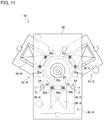
- FIG. 11 is a plan view that shows part of the drive device 10 according to the second embodiment.
- Each coil 30 of the present embodiment includes coil terminals 30a for electrically connecting the coil 30 and a circuit board 50, which will be described later.
- the coil terminals 30a protrude toward the upper side (one side of an axial direction) of the rotor 22.
- the drive device 10 of the present embodiment comprises the circuit board 50.
- FIG. 12 is a plan view of the circuit board 50. As shown in FIGS. 11 and 12 , on the circuit board 50 is formed a shaft hole 50a through which the rotating shaft 20 is inserted. On the circuit board 50, through holes 50b through which the coil terminals 30a are respectively inserted are also formed. Each coil terminal 30a is mechanically connected to the circuit board 50 using a conductive connection material, such as solder and a conductive adhesive.
- the circuit board 50 is provided with the aforementioned control unit, which controls the energization states of the coils 30 of multiple phases.
- the control unit is provided in an IC chip or the like, which is not illustrated.
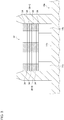
- FIG. 13 is a sectional view taken along line C-C in FIG. 11 .
- Specific positioning parts 36 among the multiple positioning parts 36 are also used for the positioning of the circuit board 50, besides the positioning of the core members 32.
- the specific positioning parts 36 in the present embodiment are the second positioning part 36-B and the third positioning part 36-C in the first core unit 42.
- Each specific positioning part 36 includes a first contact portion 52 and a second contact portion 54 that are provided at different positions along an axial direction of the rotor 22.
- the second contact portion 54 is provided closer to the distal end side along the axial direction than the first contact portion 52.
- the first contact portion 52 of each specific positioning part 36 is in contact with the core member 32-A such as to position the core member 32-A in the radial directions and circumferential directions.
- the first contact portion 52 includes the convex surface part 38, described previously, at the contact portion in contact with the core member 32.
- the circuit board 50 On the circuit board 50 are also formed two positioning holes 50c through which the two specific positioning parts 36-B and 36-C are respectively inserted. Into each positioning hole 50c, the second contact portion 54 of a specific positioning part 36 is lightly press-fitted. The second contact portion 54 of a specific positioning part 36 is in contact with the inner wall surface of a positioning hole 50c of the circuit board 50 such as to position the circuit board 50 in the radial directions and circumferential directions of the rotor 22.
- the outer peripheral surface of the first contact portion 52 and the outer peripheral surface of the second contact portion 54 in a specific positioning part 36 form circular shapes of which the centers are located along the same center line Ld. This means that, when the outer peripheral surfaces of the first contact portion 52 and the second contact portion 54 are projected onto a virtual plane perpendicular to the center line Ld of a circular shape formed by the outer peripheral surface of the first contact portion 52, the centers of the circular shapes formed by the outer peripheral surfaces are located at the same position or at nearly the same positions.
- the outer peripheral surface of the first contact portion 52 is constituted by the convex surface part 38 having an arc shape
- the outer peripheral surface of the second contact portion 54 forms a circular shape continuously provided along the entire periphery.
- the "circular shape" in the embodiment includes both a circular shape continuously provided along the entire periphery and an arc shape.
- the outer peripheral surface of the first contact portion 52 forms a circular shape of which the diameter is larger than that of a circular shape formed by the outer peripheral surface of the second contact portion 54. Advantages thereof will be described.
- the outer peripheral surfaces of the first contact portion 52 and the second contact portion 54 in a specific positioning part 36 form circular shapes of which the centers are located along the same center line Ld. Accordingly, by ensuring the dimensional accuracy of each of the outer peripheral surfaces of the first contact portion 52 and the second contact portion 54 based on the circle center line Ld in common, the relative positions of the first contact portion 52 and the second contact portion 54 of high accuracy can be ensured. Therefore, with the first contact portion 52 and the second contact portion 54 of each specific positioning part 36, the core member 32-A and the circuit board 50 can be positioned highly accurately. Consequently, the positional difference between a coil terminal 30a of a coil 30 and the corresponding through hole 50b of the circuit board 50 can be made smaller, so that the coil terminals 30a can be stably inserted through the respective through holes 50b.
- the core member 32 and the circuit board 50 can be positioned. Accordingly, compared to the case of separately providing the portions used for such positioning, the use of the materials can be reduced.
- Each specific positioning part 36 also includes a positioning portion 56 of a step shape that is in contact with the main surface of the circuit board 50 such as to position the circuit board 50 in an axial direction of the rotor 22.
- the positioning portion 56 is provided between the first contact portion 52 and the second contact portion 54.
- FIG. 14 is a plan view that shows part of the drive device 10 according to the third embodiment.
- the aforementioned embodiment describes an example in which the convex surface parts 38 are provided in the positioning parts 36, and the concave surface parts 40 are provided on the outer surfaces of the core members 32.
- the convex surface parts 38 may be provided on the outer surfaces of the core members 32, and the concave surface parts 40 may be provided in the positioning parts 36, as shown in FIG. 14 .
- each core member 32 or each positioning part 36 may include a convex surface part 38, and the other may include a concave surface part 40.
- the aforementioned effects (A)-(E) can be obtained.
- the configuration is not limited thereto.
- the drive device 10 may have a structure without the reduction mechanism 16 and may output the rotative power of the motor 12 directly to an external device.
- the positioning base may be the circuit board 50, for example.
- stator core 28 is constituted by a laminated body of multiple core plates
- the structure is not limited thereto.
- the stator core 28 may be constituted by a sintered body, such as sintered ferrite.
- stator core 28 is constituted by three core members 32
- the number of core members 32 is not limited thereto.
- the number of core members 32 may be one, two, or four or above.
- the number of positioning parts 36 provided for one core member 32 is not particularly limited.
- each first positioning part 36-A may be in contact with the corresponding core member 32 from the inner peripheral side of the core member 32 in the radial direction.
- the convex surface part 38 When the convex surface part 38 is provided in a positioning part 36, the convex surface part 38 may be provided over part of the range around the center of the circle constituted by the arc formed by the convex surface part 38.
Landscapes
- Engineering & Computer Science (AREA)
- Power Engineering (AREA)
- Iron Core Of Rotating Electric Machines (AREA)
Applications Claiming Priority (1)
| Application Number | Priority Date | Filing Date | Title |
|---|---|---|---|
| JP2017196909A JP2019071727A (ja) | 2017-10-10 | 2017-10-10 | 駆動装置 |
Publications (1)
| Publication Number | Publication Date |
|---|---|
| EP3474431A1 true EP3474431A1 (fr) | 2019-04-24 |
Family
ID=63685641
Family Applications (1)
| Application Number | Title | Priority Date | Filing Date |
|---|---|---|---|
| EP18196753.0A Withdrawn EP3474431A1 (fr) | 2017-10-10 | 2018-09-26 | Dispositif de conduite |
Country Status (3)
| Country | Link |
|---|---|
| EP (1) | EP3474431A1 (fr) |
| JP (1) | JP2019071727A (fr) |
| CN (1) | CN109660102A (fr) |
Cited By (1)
| Publication number | Priority date | Publication date | Assignee | Title |
|---|---|---|---|---|
| WO2023006457A1 (fr) * | 2021-07-30 | 2023-02-02 | HELLA GmbH & Co. KGaA | Moteur électrique pour actionneur |
Citations (6)
| Publication number | Priority date | Publication date | Assignee | Title |
|---|---|---|---|---|
| US5880551A (en) * | 1996-10-21 | 1999-03-09 | Sonceboz Sa | Polyphase motor, particularly for driving an indicator needle |
| EP1096643A2 (fr) * | 1999-10-25 | 2001-05-02 | Hitachi, Ltd. | Machine électrique rotative avec position de stator déplacée d'un angle déterminé |
| JP2002359940A (ja) * | 2001-06-01 | 2002-12-13 | Mitsubishi Electric Corp | ステータコアおよびこのステータコアを適用した回転電動機 |
| DE10341443A1 (de) * | 2003-09-09 | 2005-05-12 | Buhler Motor Gmbh | Stellantrieb und Verfahren zu seiner Herstellung |
| US20100314962A1 (en) * | 2009-06-15 | 2010-12-16 | Tamron Co., Ltd. | Three-Phase Brushless DC Motor |
| JP2014241683A (ja) | 2013-06-12 | 2014-12-25 | 日本電産サンキョー株式会社 | モータ |
Family Cites Families (2)
| Publication number | Priority date | Publication date | Assignee | Title |
|---|---|---|---|---|
| CN201523267U (zh) * | 2009-09-21 | 2010-07-07 | 江阴江顺精密机械零部件有限公司 | 电机定子矽钢片定位装置 |
| CN103051074B (zh) * | 2011-10-11 | 2015-06-17 | 浙江特种电机有限公司 | 一种交叉叠扣式无刷直流变频电机的定子铁芯 |
-
2017
- 2017-10-10 JP JP2017196909A patent/JP2019071727A/ja active Pending
-
2018
- 2018-09-18 CN CN201811086333.5A patent/CN109660102A/zh active Pending
- 2018-09-26 EP EP18196753.0A patent/EP3474431A1/fr not_active Withdrawn
Patent Citations (6)
| Publication number | Priority date | Publication date | Assignee | Title |
|---|---|---|---|---|
| US5880551A (en) * | 1996-10-21 | 1999-03-09 | Sonceboz Sa | Polyphase motor, particularly for driving an indicator needle |
| EP1096643A2 (fr) * | 1999-10-25 | 2001-05-02 | Hitachi, Ltd. | Machine électrique rotative avec position de stator déplacée d'un angle déterminé |
| JP2002359940A (ja) * | 2001-06-01 | 2002-12-13 | Mitsubishi Electric Corp | ステータコアおよびこのステータコアを適用した回転電動機 |
| DE10341443A1 (de) * | 2003-09-09 | 2005-05-12 | Buhler Motor Gmbh | Stellantrieb und Verfahren zu seiner Herstellung |
| US20100314962A1 (en) * | 2009-06-15 | 2010-12-16 | Tamron Co., Ltd. | Three-Phase Brushless DC Motor |
| JP2014241683A (ja) | 2013-06-12 | 2014-12-25 | 日本電産サンキョー株式会社 | モータ |
Cited By (1)
| Publication number | Priority date | Publication date | Assignee | Title |
|---|---|---|---|---|
| WO2023006457A1 (fr) * | 2021-07-30 | 2023-02-02 | HELLA GmbH & Co. KGaA | Moteur électrique pour actionneur |
Also Published As
| Publication number | Publication date |
|---|---|
| CN109660102A (zh) | 2019-04-19 |
| JP2019071727A (ja) | 2019-05-09 |
Similar Documents
| Publication | Publication Date | Title |
|---|---|---|
| JP4946625B2 (ja) | モータ | |
| JP6511137B2 (ja) | ブラシレスモータ | |
| US9847689B2 (en) | Motor | |
| CN101421909A (zh) | 磁分解器和制造该磁分解器的方法 | |
| US11165293B2 (en) | Rotor and motor | |
| US10782149B2 (en) | Sensor module and motor comprising same | |
| US9515533B2 (en) | Rotary body driving apparatus | |
| CN113273054B (zh) | 马达 | |
| KR20130032245A (ko) | 고정자 코어 및 고정자 | |
| EP3316451A1 (fr) | Dispositif de moteur | |
| US20180138777A1 (en) | Motor, motor device and pointer type display device | |
| US11888355B2 (en) | Rotor and motor including same | |
| CN104638799B (zh) | 马达 | |
| KR100854025B1 (ko) | 구동장치 | |
| CN102128640B (zh) | 多次旋转角度传感器 | |
| CN104638802B (zh) | 马达及其制造方法 | |
| CN110971053A (zh) | 电动机 | |
| US20190356209A1 (en) | Motor device and pointer-type display device | |
| WO2018180634A1 (fr) | Moteur | |
| JP2019071727A (ja) | 駆動装置 | |
| CN110268612B (zh) | 直线运动执行元件 | |
| CN203554181U (zh) | 马达 | |
| JP2017005857A (ja) | ロータ | |
| CN111480281A (zh) | 电磁钢板、转子铁芯、转子以及马达 | |
| JP6208985B2 (ja) | モータ |
Legal Events
| Date | Code | Title | Description |
|---|---|---|---|
| PUAI | Public reference made under article 153(3) epc to a published international application that has entered the european phase |
Free format text: ORIGINAL CODE: 0009012 |
|
| AK | Designated contracting states |
Kind code of ref document: A1 Designated state(s): AL AT BE BG CH CY CZ DE DK EE ES FI FR GB GR HR HU IE IS IT LI LT LU LV MC MK MT NL NO PL PT RO RS SE SI SK SM TR |
|
| AX | Request for extension of the european patent |
Extension state: BA ME |
|
| 17P | Request for examination filed |
Effective date: 20191022 |
|
| RBV | Designated contracting states (corrected) |
Designated state(s): AL AT BE BG CH CY CZ DE DK EE ES FI FR GB GR HR HU IE IS IT LI LT LU LV MC MK MT NL NO PL PT RO RS SE SI SK SM TR |
|
| STAA | Information on the status of an ep patent application or granted ep patent |
Free format text: STATUS: THE APPLICATION HAS BEEN WITHDRAWN |
|
| 18W | Application withdrawn |
Effective date: 20200806 |