EP3475112B1 - Integrated coolant bottle assembly - Google Patents
Integrated coolant bottle assembly Download PDFInfo
- Publication number
- EP3475112B1 EP3475112B1 EP17737108.5A EP17737108A EP3475112B1 EP 3475112 B1 EP3475112 B1 EP 3475112B1 EP 17737108 A EP17737108 A EP 17737108A EP 3475112 B1 EP3475112 B1 EP 3475112B1
- Authority
- EP
- European Patent Office
- Prior art keywords
- reservoir
- section
- interface
- components
- liquid medium
- Prior art date
- Legal status (The legal status is an assumption and is not a legal conclusion. Google has not performed a legal analysis and makes no representation as to the accuracy of the status listed.)
- Active
Links
Images




Classifications
-
- H—ELECTRICITY
- H01—ELECTRIC ELEMENTS
- H01M—PROCESSES OR MEANS, e.g. BATTERIES, FOR THE DIRECT CONVERSION OF CHEMICAL ENERGY INTO ELECTRICAL ENERGY
- H01M10/00—Secondary cells; Manufacture thereof
- H01M10/60—Heating or cooling; Temperature control
- H01M10/61—Types of temperature control
- H01M10/613—Cooling or keeping cold
-
- B—PERFORMING OPERATIONS; TRANSPORTING
- B60—VEHICLES IN GENERAL
- B60L—PROPULSION OF ELECTRICALLY-PROPELLED VEHICLES; SUPPLYING ELECTRIC POWER FOR AUXILIARY EQUIPMENT OF ELECTRICALLY-PROPELLED VEHICLES; ELECTRODYNAMIC BRAKE SYSTEMS FOR VEHICLES IN GENERAL; MAGNETIC SUSPENSION OR LEVITATION FOR VEHICLES; MONITORING OPERATING VARIABLES OF ELECTRICALLY-PROPELLED VEHICLES; ELECTRIC SAFETY DEVICES FOR ELECTRICALLY-PROPELLED VEHICLES
- B60L1/00—Supplying electric power to auxiliary equipment of vehicles
- B60L1/003—Supplying electric power to auxiliary equipment of vehicles to auxiliary motors, e.g. for pumps, compressors
-
- B—PERFORMING OPERATIONS; TRANSPORTING
- B60—VEHICLES IN GENERAL
- B60K—ARRANGEMENT OR MOUNTING OF PROPULSION UNITS OR OF TRANSMISSIONS IN VEHICLES; ARRANGEMENT OR MOUNTING OF PLURAL DIVERSE PRIME-MOVERS IN VEHICLES; AUXILIARY DRIVES FOR VEHICLES; INSTRUMENTATION OR DASHBOARDS FOR VEHICLES; ARRANGEMENTS IN CONNECTION WITH COOLING, AIR INTAKE, GAS EXHAUST OR FUEL SUPPLY OF PROPULSION UNITS IN VEHICLES
- B60K11/00—Arrangement in connection with cooling of propulsion units
- B60K11/02—Arrangement in connection with cooling of propulsion units with liquid cooling
-
- B—PERFORMING OPERATIONS; TRANSPORTING
- B60—VEHICLES IN GENERAL
- B60L—PROPULSION OF ELECTRICALLY-PROPELLED VEHICLES; SUPPLYING ELECTRIC POWER FOR AUXILIARY EQUIPMENT OF ELECTRICALLY-PROPELLED VEHICLES; ELECTRODYNAMIC BRAKE SYSTEMS FOR VEHICLES IN GENERAL; MAGNETIC SUSPENSION OR LEVITATION FOR VEHICLES; MONITORING OPERATING VARIABLES OF ELECTRICALLY-PROPELLED VEHICLES; ELECTRIC SAFETY DEVICES FOR ELECTRICALLY-PROPELLED VEHICLES
- B60L58/00—Methods or circuit arrangements for monitoring or controlling batteries or fuel cells, specially adapted for electric vehicles
- B60L58/10—Methods or circuit arrangements for monitoring or controlling batteries or fuel cells, specially adapted for electric vehicles for monitoring or controlling batteries
- B60L58/24—Methods or circuit arrangements for monitoring or controlling batteries or fuel cells, specially adapted for electric vehicles for monitoring or controlling batteries for controlling the temperature of batteries
- B60L58/27—Methods or circuit arrangements for monitoring or controlling batteries or fuel cells, specially adapted for electric vehicles for monitoring or controlling batteries for controlling the temperature of batteries by heating
-
- H—ELECTRICITY
- H01—ELECTRIC ELEMENTS
- H01M—PROCESSES OR MEANS, e.g. BATTERIES, FOR THE DIRECT CONVERSION OF CHEMICAL ENERGY INTO ELECTRICAL ENERGY
- H01M10/00—Secondary cells; Manufacture thereof
- H01M10/60—Heating or cooling; Temperature control
- H01M10/63—Control systems
-
- H—ELECTRICITY
- H01—ELECTRIC ELEMENTS
- H01M—PROCESSES OR MEANS, e.g. BATTERIES, FOR THE DIRECT CONVERSION OF CHEMICAL ENERGY INTO ELECTRICAL ENERGY
- H01M10/00—Secondary cells; Manufacture thereof
- H01M10/60—Heating or cooling; Temperature control
- H01M10/65—Means for temperature control structurally associated with the cells
- H01M10/656—Means for temperature control structurally associated with the cells characterised by the type of heat-exchange fluid
- H01M10/6567—Liquids
-
- B—PERFORMING OPERATIONS; TRANSPORTING
- B60—VEHICLES IN GENERAL
- B60K—ARRANGEMENT OR MOUNTING OF PROPULSION UNITS OR OF TRANSMISSIONS IN VEHICLES; ARRANGEMENT OR MOUNTING OF PLURAL DIVERSE PRIME-MOVERS IN VEHICLES; AUXILIARY DRIVES FOR VEHICLES; INSTRUMENTATION OR DASHBOARDS FOR VEHICLES; ARRANGEMENTS IN CONNECTION WITH COOLING, AIR INTAKE, GAS EXHAUST OR FUEL SUPPLY OF PROPULSION UNITS IN VEHICLES
- B60K1/00—Arrangement or mounting of electrical propulsion units
- B60K2001/003—Arrangement or mounting of electrical propulsion units with means for cooling the electrical propulsion units
-
- B—PERFORMING OPERATIONS; TRANSPORTING
- B60—VEHICLES IN GENERAL
- B60K—ARRANGEMENT OR MOUNTING OF PROPULSION UNITS OR OF TRANSMISSIONS IN VEHICLES; ARRANGEMENT OR MOUNTING OF PLURAL DIVERSE PRIME-MOVERS IN VEHICLES; AUXILIARY DRIVES FOR VEHICLES; INSTRUMENTATION OR DASHBOARDS FOR VEHICLES; ARRANGEMENTS IN CONNECTION WITH COOLING, AIR INTAKE, GAS EXHAUST OR FUEL SUPPLY OF PROPULSION UNITS IN VEHICLES
- B60K1/00—Arrangement or mounting of electrical propulsion units
- B60K2001/008—Arrangement or mounting of electrical propulsion units with means for heating the electrical propulsion units
-
- B—PERFORMING OPERATIONS; TRANSPORTING
- B60—VEHICLES IN GENERAL
- B60L—PROPULSION OF ELECTRICALLY-PROPELLED VEHICLES; SUPPLYING ELECTRIC POWER FOR AUXILIARY EQUIPMENT OF ELECTRICALLY-PROPELLED VEHICLES; ELECTRODYNAMIC BRAKE SYSTEMS FOR VEHICLES IN GENERAL; MAGNETIC SUSPENSION OR LEVITATION FOR VEHICLES; MONITORING OPERATING VARIABLES OF ELECTRICALLY-PROPELLED VEHICLES; ELECTRIC SAFETY DEVICES FOR ELECTRICALLY-PROPELLED VEHICLES
- B60L2200/00—Type of vehicles
- B60L2200/10—Air crafts
-
- B—PERFORMING OPERATIONS; TRANSPORTING
- B60—VEHICLES IN GENERAL
- B60L—PROPULSION OF ELECTRICALLY-PROPELLED VEHICLES; SUPPLYING ELECTRIC POWER FOR AUXILIARY EQUIPMENT OF ELECTRICALLY-PROPELLED VEHICLES; ELECTRODYNAMIC BRAKE SYSTEMS FOR VEHICLES IN GENERAL; MAGNETIC SUSPENSION OR LEVITATION FOR VEHICLES; MONITORING OPERATING VARIABLES OF ELECTRICALLY-PROPELLED VEHICLES; ELECTRIC SAFETY DEVICES FOR ELECTRICALLY-PROPELLED VEHICLES
- B60L2200/00—Type of vehicles
- B60L2200/24—Personal mobility vehicles
-
- B—PERFORMING OPERATIONS; TRANSPORTING
- B60—VEHICLES IN GENERAL
- B60L—PROPULSION OF ELECTRICALLY-PROPELLED VEHICLES; SUPPLYING ELECTRIC POWER FOR AUXILIARY EQUIPMENT OF ELECTRICALLY-PROPELLED VEHICLES; ELECTRODYNAMIC BRAKE SYSTEMS FOR VEHICLES IN GENERAL; MAGNETIC SUSPENSION OR LEVITATION FOR VEHICLES; MONITORING OPERATING VARIABLES OF ELECTRICALLY-PROPELLED VEHICLES; ELECTRIC SAFETY DEVICES FOR ELECTRICALLY-PROPELLED VEHICLES
- B60L2200/00—Type of vehicles
- B60L2200/32—Waterborne vessels
-
- B—PERFORMING OPERATIONS; TRANSPORTING
- B60—VEHICLES IN GENERAL
- B60L—PROPULSION OF ELECTRICALLY-PROPELLED VEHICLES; SUPPLYING ELECTRIC POWER FOR AUXILIARY EQUIPMENT OF ELECTRICALLY-PROPELLED VEHICLES; ELECTRODYNAMIC BRAKE SYSTEMS FOR VEHICLES IN GENERAL; MAGNETIC SUSPENSION OR LEVITATION FOR VEHICLES; MONITORING OPERATING VARIABLES OF ELECTRICALLY-PROPELLED VEHICLES; ELECTRIC SAFETY DEVICES FOR ELECTRICALLY-PROPELLED VEHICLES
- B60L2200/00—Type of vehicles
- B60L2200/36—Vehicles designed to transport cargo, e.g. trucks
-
- B—PERFORMING OPERATIONS; TRANSPORTING
- B60—VEHICLES IN GENERAL
- B60Y—INDEXING SCHEME RELATING TO ASPECTS CROSS-CUTTING VEHICLE TECHNOLOGY
- B60Y2200/00—Type of vehicle
- B60Y2200/90—Vehicles comprising electric prime movers
- B60Y2200/91—Electric vehicles
-
- H—ELECTRICITY
- H01—ELECTRIC ELEMENTS
- H01M—PROCESSES OR MEANS, e.g. BATTERIES, FOR THE DIRECT CONVERSION OF CHEMICAL ENERGY INTO ELECTRICAL ENERGY
- H01M2220/00—Batteries for particular applications
- H01M2220/20—Batteries in motive systems, e.g. vehicle, ship, plane
-
- Y—GENERAL TAGGING OF NEW TECHNOLOGICAL DEVELOPMENTS; GENERAL TAGGING OF CROSS-SECTIONAL TECHNOLOGIES SPANNING OVER SEVERAL SECTIONS OF THE IPC; TECHNICAL SUBJECTS COVERED BY FORMER USPC CROSS-REFERENCE ART COLLECTIONS [XRACs] AND DIGESTS
- Y02—TECHNOLOGIES OR APPLICATIONS FOR MITIGATION OR ADAPTATION AGAINST CLIMATE CHANGE
- Y02E—REDUCTION OF GREENHOUSE GAS [GHG] EMISSIONS, RELATED TO ENERGY GENERATION, TRANSMISSION OR DISTRIBUTION
- Y02E60/00—Enabling technologies; Technologies with a potential or indirect contribution to GHG emissions mitigation
- Y02E60/10—Energy storage using batteries
-
- Y—GENERAL TAGGING OF NEW TECHNOLOGICAL DEVELOPMENTS; GENERAL TAGGING OF CROSS-SECTIONAL TECHNOLOGIES SPANNING OVER SEVERAL SECTIONS OF THE IPC; TECHNICAL SUBJECTS COVERED BY FORMER USPC CROSS-REFERENCE ART COLLECTIONS [XRACs] AND DIGESTS
- Y02—TECHNOLOGIES OR APPLICATIONS FOR MITIGATION OR ADAPTATION AGAINST CLIMATE CHANGE
- Y02T—CLIMATE CHANGE MITIGATION TECHNOLOGIES RELATED TO TRANSPORTATION
- Y02T10/00—Road transport of goods or passengers
- Y02T10/60—Other road transportation technologies with climate change mitigation effect
- Y02T10/70—Energy storage systems for electromobility, e.g. batteries
Definitions
- the present disclosure relates generally to thermal management systems such as those that are implemented within vehicles.
- Electric motors can generate considerable heat, especially in the traction motor of a vehicle where size and weight constraints are coupled with the need for high power output.
- Electric motor overheating causes the motor winding insulation to deteriorate quickly. For every 10-degree Celsius rise in electric motor temperature, insulation life is cut in half.
- Another issue caused by overheating is that permanent magnets in the rotor lose their magnetic properties as they overheat, resulting in a loss of efficiency.
- an increase in temperature of the copper windings reduces efficiency of the induction motor-copper electrical resistivity increases 4% for every 10-degree Celsius temperature increase.
- the architecture of the electric motor cooling system must operate efficiently with large variations in ambient operating environment as the electric motor may be subjected to a wide range of ambient temperatures, humidity levels, and/or dust/dirt levels.
- the prior art solutions for thermal systems that perform cooling of various components within a vehicle typically include a coolant reservoir that stores coolant of some desired material that then gets passed via hosing to one or more other components within the vehicle.
- the coolant reservoir is typically located in one location and is interconnected with one or more other components that are separately located via hosing.
- Such a prior art implementation provides a significant number of connections, hosing, fasteners, etc. and also provides a large number of possible failure points within the overall thermal system.
- a prior art coolant reservoir assembly will typically require mounting of multiple discrete components to the vehicle, the interconnection of multiple electrical connectors for different components, and the connection of multiple hoses and hose clamps to route the flow of coolant to these various components located in different respective locations.
- the multi-faceted construction and assembly of these parts is time-intensive and gives rise to multiple points of potential failure in hoses, clamps, electrical connections, etc..
- US 2009/151903 , US 2007/044938 , and US 2012/168118 Typical examples of the prior art are shown in US 2009/151903 , US 2007/044938 , and US 2012/168118 .
- US 2009/0151903 A1 discloses a coolant reservoir tank for fuel-cell vehicle which includes a tank body, inlet and outlet ports, and a pipe to the reservoir tank and connected to the inlet and outlet ports via clamps or similar hose connectors.
- US 2012/0168118 A1 describes a coolant flow control management system including an integrated pump coolant flow control and heat exchange device for delivering engine coolant to and from an engine.
- the invention provides a reservoir according to claim 1. Embodiments are defined in the dependent claims.
- FIG. 1 illustrates an example 100 of basic components of a battery powered electric vehicle (electric vehicle).
- the electric vehicle includes at least one drive motor (traction motor) 102A and/or 102B, at least one gear box 104A and/or 104B coupled to a corresponding drive motor 102A and/or 102B, a battery 106 and electronics 108.
- the battery 106 provides electricity to the power electronics of the electric vehicle and to propel the electric vehicle using the drive motor 102A and/or 102B.
- the electric vehicle includes a large number of other components that are not described herein but known to one of ordinary skill. While the construct of the electric vehicle of FIG. 1 is shown to have four wheels, differing electric vehicles may have fewer or more than four wheels. Further, differing types of electric vehicles may incorporate the inventive concepts described herein, including motor cycles, aircraft, trucks, boats, train engines, among other types of vehicles.
- FIG. 2 illustrates an example 200 of components of a drive motor cooling system and a battery heating system, both constructed and operating according to a disclosed embodiment.
- the drive motor cooling system includes a drive motor fluid pump system 202 having a drive motor fluid pump 204, a coolant reservoir 206 and electronics 208.
- the fluid is oil.
- the drive motor fluid pump 204 pumps fluid between the drive motor 102A and/or 102B, the fluid reservoir 206, and a heat exchanger 210.
- the heat exchanger exchanges heat from the oil based drive motor fluid with water or alcohol based coolant and routes the water or alcohol based coolant to a radiator 212 for cooling.
- any desired liquid medium for coolant may be used in any desired embodiment.
- the heat exchanger may include another pump to circulate the water or alcohol based coolant.
- the heat exchanger 210 in the illustrated embodiment couples to coolant tubes 214 adjacent to or running through the components of the battery 106.
- the drive motor fluid pump 204 may couple directly to the coolant tubes 214 of the battery 106 and/or to the radiator 212.
- the drive motor fluid pump 204 is controlled by electronics 208, which may include a digital computer and other related components.
- the drive motor fluid pump 204 may include control valves to control flow of fluid between the drive motor 102A and/or 102B, the reservoir 206, and the heat exchanger 210 (and battery 106 coolant tubes 214 in other embodiments).
- the heat exchanger 210 may also include valves to direct the flow of coolant to the battery 106 coolant tubes 214 and to the radiator 212, under control of electronics 208 in some embodiments.
- reservoirs for use in thermal systems are provided herein. Any of these various examples of reservoirs may be used within various applications. Some applications include those tailored for any desired example of a battery powered electric vehicle (electric vehicle) such as described with respect to FIG. 1 and may be tailored for any desired example of a drive motor cooling system and/or a battery heating system as described with respect to FIG. 2 .
- Such examples of reservoirs may be viewed as being part of an integrated coolant bottle assembly.
- such a reservoir may be viewed as a bottle, a coolant bottle, etc. that is a portion of an integrated coolant bottle assembly that allows for one or more components to be coupled to, attached to, and/or connected to the reservoir.
- the reservoir itself may be fabricated such that one or more integrated channels are included within one or more portion of the reservoir that allow for one or more pathways between the one or more components, one or more hose interfaces, etc.
- FIG. 3A is a diagram illustrating an example 301 of a reservoir for use within a thermal system in accordance with the present invention.
- a reservoir 206-1 include an input/output port 310-1 via which some liquid medium (e.g., any desired type of fluid such as coolant liquid, anti-freeze, water, an alcohol based agent, a heating agent, etc. and/or any desired combination of any such liquid mediums) may be added to the reservoir 206-1 and/or removed there from.
- some liquid medium e.g., any desired type of fluid such as coolant liquid, anti-freeze, water, an alcohol based agent, a heating agent, etc. and/or any desired combination of any such liquid mediums
- Such an input/output port 310-1 may include a cap or some secured mechanism by which the liquid medium is prevented from escaping from the reservoir 206-1 and to ensure other elements do not enter the reservoir 206-1.
- the reservoir 206-1 is designed such that one or more components that operate in accordance with the thermal system (e.g., shown as components 320-1 and 320-2).
- components may include anything that is part of the thermal system and/or anything that is part of a system in which the thermal system is situated.
- a thermal system implemented within a vehicle (e.g., battery powered electric vehicle (electric vehicle)
- examples of such components may include any one or more of a pump (e.g., a battery pump, a powertrain pump, etc.), a chiller, a heater, a filter, an aerator, a fan, a radiator, etc. and/or any other components known in the art as related to such thermal systems.
- the reservoir 206-1 includes one or more interfaces at which one or more of the components 320-1 and 320-2 may be coupled, attached, and/or connected to the reservoir 206-1.
- the reservoir 206-1 may optionally include one or more hose interfaces 340-1 at which one or more hoses may be coupled to, attached to, and/or connected to the reservoir 206-1.
- the reservoir 206-1 allows for both integration of one or more components as well as for hose-based interfacing of one or more other components.
- the reservoir 206-1 include an integrated channel 330-1 via which the liquid medium is transported between the components 320-1 and 320-2.
- the integrated channel 330-1 is formed within at least one portion of the reservoir 206-1 during its fabrication, molding, generation, etc.
- the integrated channel 330-1 is formed therein and between interfaces at which the components 320-1 and 320-2 may be connected. Then, when one or both of the components 320-1 and 320-2 is/are interfaced with the reservoir 206-1, the integrated channel 330-1 provides interconnection between the components 320-1 and 320-2.
- such integrated channels may be formed based on hollowed using slides that are pulled along the axis of a cylindrical channel. Such a technique may be used to form multiple integrated channels (e.g., flow channels) in several orientations within a given portion of a reservoir. In addition, such construction may be used to form integrated tees that would have otherwise required external hoses and fittings.
- the reservoir itself includes various integrated channels that operate to direct the flow of the liquid medium directly into various components that are integrated with the coolant bottle (e.g., such as a chiller, a battery pump, a powertrain pump, etc.).
- the coolant bottle e.g., such as a chiller, a battery pump, a powertrain pump, etc.
- a unitary reservoir design structure can be formed to generate an integrated coolant bottle assembly, and such an integrated coolant bottle assembly can then be bolted to and installed within a vehicle relatively easily (e.g., using as few as two bolts in some examples).
- such an integrated coolant bottle assembly can be connected to such a vehicle's electrical system using a single electrical connector that includes the respective electrical leads therein that correspond to each of the pertinent electrical components as opposed to requiring time-consuming connection of each respective electrical component via a separate respective electrical connector.
- temperature sensors are also integrated into specific integrated channels (e.g., flow channels) at locations where it is desired to obtain measurements of the fluid medium. Such integration of temperature sensors directly into the ports of the coolant bottle eliminates the need for additional external parts, seals and clamps.
- FIG. 3B is a diagram illustrating another example 302 of a reservoir for use within a thermal system in accordance with the present invention.
- the reservoir 206-2 includes an input/output port 310-2. Also, the reservoir 206-2 has integrated therewith components 320-3, 320-3, 320-5, and 320-6 that are attached thereto. Moreover, the reservoir 206-2 has integrated therewith a pump 312 and a chiller 314. Note that different embodiments of reservoirs may be of different sizes, shapes, forms, etc. and may include different respective numbers and types of components integrated therewith as may be desired and/or needed within a particular implementation and design of a thermal system. In addition, reservoir 206-2 optionally includes hose interfaces 340-2 and 340-3.
- any number of integrated channels may be included within a portion of the reservoir 206-2.
- an integrated channel 330-2 provides a pathway for the liquid medium between chiller 314 and component 320-5.
- Other integrated channels are also shown as providing respective pathways between various elements associated with the reservoir 206-2 in the diagram.
- the manner by which any of the pump 314, chiller 314, and components 320-3 to 320-5 interface to, connect to, couple to, etc. the reservoir 206-2 may be varied.
- the component 320-3 is shown as be associated with and interfaces to the reservoir 206-2 at a lower end portion of the reservoir 206-2.
- the pump 312 and chiller 314 are shown as be associated with and interfaces to the reservoir 206-2 at upper respective portions of the reservoir 206-2.
- the component 320-6 is shown as being substantially centrally associated with the reservoir 206-2 and being provided integrated pathways to multiple respective other components (e.g., components 320-4 and 320-5 and pump 312 and optionally to hose interface 340-3).
- FIG. 3C is a diagram illustrating another example 303 of a reservoir for use within a thermal system in accordance with the present invention.
- the reservoir 206-3 includes an input/output port 310-3 and at least two components 330-7 and 330-8.
- reservoir 206-3 includes a recess into which the component 330-8 fits when interfaced to the reservoir 206-3.
- a reservoir designed in accordance with the principles herein may include any number of recesses, orifices, faces, ports, etc. that allow one or more components to interface to the reservoir.
- the reservoir 206-3 itself includes an integrated channel 330-3 that provides a pathway for the liquid medium between components 330-7 and 330-8.
- a particular design of a reservoir can include any one or more types of interfaces that are suitably designed and tailored to allow for the coupling, connection, etc. of any desired types of components to the reservoir 206-3.
- any one or more hose interfaces may also be included within a given design of a reservoir. A designer has total flexibility to decide how many components to integrate to the reservoir design and how many, if any, are to interact with the reservoir via hose interfaces.
- FIG. 3D is a diagram illustrating another example 304 of a reservoir for use within a thermal system in accordance with the present invention.
- a reservoir 206-4 includes a first section of reservoir 206-4 and a second section of reservoir 206-4 that are joined together via a reservoir interface 304 to form the reservoir 206-4.
- the connectivity, coupling, joining, etc. at the reservoir interface 304 may be achieved using any desired means (e.g., a weld interface, a glued interface, a hot molded interface, a hot plate weld interface, thermal weld interface, a sonic weld interface, an ultrasonic weld interface, etc. and/or any other means by which two sections of a reservoir may be joined together).
- a reservoir as designed herein can include multiple sections (e.g., two halves) of the reservoir that are manufactured with integrated channels (e.g., flow channels) that are formed by the intersection of the core and cavity of the mold(s) of the respective sections of the reservoir.
- integrated channels e.g., flow channels
- the reservoir of this diagram may be viewed as including a first section and a second section.
- the second section is joined to the first section at a reservoir interface thereby forming a reservoir that is configured to facilitate at least one of storage or flow of a liquid medium.
- the first section or the second section includes an integrated channel that provides a pathway for the flow of the liquid medium.
- the component interface is also configured to facilitate connection of a component thereto, and the integrated channel provides the pathway for the flow of the liquid medium to or from the component interface.
- the component may include any of a number of different types of components including any one of a pump, a battery pump, a powertrain pump, a chiller, a heater, a filter, an aerator, a fan, a radiator, etc. and/or any other components known in the art as related to such thermal systems.
- the reservoir includes a first component interface configured to facilitate connection of a first component thereto as well as a second component interface configured to facilitate connection of a second component thereto.
- the integrated channel provides the pathway for the flow of the liquid medium from the first component interface to the second component interface.
- the reservoir includes a hose interface configured to facilitate connection of a hose to transport the liquid medium to or to receive the liquid medium from another component that is located remotely from the reservoir and coupled to the reservoir by the hose.
- the reservoir includes a recess configured to facilitate connection of a component.
- the integrated channel provides the pathway for the flow of the liquid medium to or from the recess.
- FIG. 4A is a diagram illustrating another example 401 of a reservoir for use within a thermal system in accordance with the present invention.
- a reservoir 206-5 includes a first section of reservoir 206-5 and a second section of reservoir 206-6 that are joined together at a first reservoir interface 304-1 to form part of the reservoir 206-5.
- the reservoir 206-5 includes another section of reservoir 206-5 that is joined to the second section of reservoir 206-6 at a second reservoir interface 304-2 to form another part of the reservoir 206-5.
- any number (e.g., two or more) of different sections of a reservoir may be joined together at any desired number of reservoir interfaces (e.g., a first reservoir interface 304-1, a second reservoir interface 304-2, and so on to an n th reservoir interface 304-3).
- FIG. 4B is a diagram illustrating another example 402 of a reservoir for use within a thermal system in accordance with the present invention.
- a reservoir 206-6 includes multiple section of reservoir 206-6 (e.g., including a first section of reservoir 206-6) that are joined at various reservoir interfaces 304-4 and 304-5. This diagram shows an example of four substantially similarly-sized sections of the reservoir 206-6.
- FIG. 4C is a diagram illustrating another example 403 of a reservoir for use within a thermal system in accordance with the present invention.
- a reservoir 206-7 includes multiple section of reservoir 206-7 (e.g., including a first section of reservoir 206-7) that are joined at various reservoir interfaces (e.g., including reservoir interface 304-6). This diagram shows an example of three sections of the reservoir 206-7 that are of different respective sizes.
- FIG. 4D is a diagram illustrating another example 404 of a reservoir for use within a thermal system in accordance with the present invention.
- a reservoir 206-8 includes two respective sections that are joined together and form a channel at the reservoir interface 304-7 between the two respective sections.
- An integrated channel 330-3 is formed at the interface between the two respective sections of the reservoir 206-8 and provides a pathway for the liquid medium to be transported between components 330-9 and 330-10.
- a first portion of the integrated channel 330-3 is within a first or top section of the reservoir 206-8, and a second portion of the integrated channel 330-3 is within the second or bottom section of the reservoir 206-8.
- the sections of the reservoir 206-8 are fabricated such that when they are joined together, the integrated channel 330-3 is formed at the reservoir interface 304-7 where the first portion of the integrated channel 330-3 complementarily aligns with second portion of the integrated channel 330-3 at the reservoir interface 304-7.
- any desired proportions of the integrated channel 330-3 may be fabricated using the two respective sections of the reservoir 206-8 (e.g., one-half in each section, a fourth in one section and three-fourths in the other section, X% in in one section and (1-X)% in the other section wherein X is any desired number between 0 and 100).
- one or more integrated channels may be formed at a reservoir interface, and one or more other integrated channels may be included within one or more sections of a reservoir.
- the integrated channels e.g., flow paths
- the integrated channels can be formed by creating recesses within respective portions of the reservoir structures, forming smooth cylindrical or tubular flow channels, with no weld points located along the channels themselves.
- FIG. 5 is a diagram illustrating an example 500 of a portion of a reservoir for use within a thermal system in accordance with the present invention.
- This diagram shows a first section of reservoir 206-9 that includes multiple hose interfaces (e.g., hose interfaces 340-4, 340-5, 340-6, and 340-7) and multiple integrated channels (e.g., integrated channels 330-4, 330-5, and 330-6).
- this first section of reservoir 206-9 includes a multi-path valve mounting interface 510 at which a multi-path valve may be interfaced with this first section of reservoir 206-9.
- such a multi-path valve is included in within the multi-path valve mounting interface 510 that provides for a smooth, unobstructed and integrated multi-path valve to be interfaced within the first section of reservoir 206-9.
- the valve stem of such a multi-path valve is uniquely shaped, and its orientation can be manipulated to achieve desired flow configurations, or combinations of flow configurations, including blend modes. Using the valve stem of such a multi-path valve allows the coolant loops to be combined in parallel, or operated in series mode, as well as allowing certain thermal components to be bypassed when not required.
- reservoirs may have different shapes, forms, etc. and may include different types of mounting interfaces to allow for different types of components to be mounted onto the reservoir.
- FIG. 6 is a diagram illustrating another example 600 of a portion of a reservoir for use within a thermal system in accordance with the present invention.
- This diagram shows a first section of reservoir 206-10 that includes at least one hose interface (e.g., hose interface 340-8), at least one integrated channel (e.g., integrated channel 330-7), and at least one component mounting interface (e.g., component mounting interface 610).
- this diagram shows a reservoir interface 304-8 at which the first section of reservoir 206-10 may be joined with at least one other section of reservoir 206-10.
- the example 600 that shows the first section of reservoir 206-9 corresponds to another perspective view of the first section of reservoir 206-9 in the example 500 of FIG. 5 .
- FIG. 7 is a diagram illustrating another example 700 of a portion of a reservoir for use within a thermal system in accordance with the present invention.
- This diagram shows a first section of reservoir 206-11 that includes at least one hose interface (e.g., hose interface 340-9).
- this diagram shows multiple reservoir interfaces 304-9 including the section's perimeter edge and internal faces, edges, surfaces, etc.
- the first section of reservoir 206-11 may be joined to another section of reservoir 206-11 not only along the section's perimeter edge, but also at one or more additional internal faces, edges, surfaces, etc. Note that such internal faces, edges, surfaces, etc. may be designed so that they substantially or approximately align with other internal faces, edges, surfaces, etc.
- the example 700 that shows the first section of reservoir 206-11 corresponds to another perspective view of the first section of reservoir 206-9 in the example 500 of FIG. 5 and/or of the first section of reservoir 206-10 in the example 600 of FIG. 6 .
- the hose interface 340-9 corresponds to another perspective view of hose interface 340-4 as shown in FIG. 5 .
- FIG. 8 is a diagram illustrating another example 800 of a portion of a reservoir for use within a thermal system in accordance with the present invention.
- This diagram shows a first section of reservoir 206-12 that includes at least one component mounting interface that allows for at least one component to interface to, connect to, couple to, etc. the reservoir 206-12.
- the first section of reservoir 206-12 includes component mounting interface 610-1 that allows for component 320-11 to be mounted thereon.
- any of the various components described herein may be interfaced to, connects to, couples to, etc. a particular section of a reservoir before the reservoir (and its accompanying components) are installed within a thermal system such as may be included within a vehicle (e.g., battery powered electric vehicle (electric vehicle), a conventionally-gas powered vehicle, a diesel fuel powered vehicle, a natural gas powered vehicle, a solar powered vehicle, and/or any other type of vehicle).
- a vehicle e.g., battery powered electric vehicle (electric vehicle), a conventionally-gas powered vehicle, a diesel fuel powered vehicle, a natural gas powered vehicle, a solar powered vehicle, and/or any other type of vehicle.
- a reservoir designed in accordance with such an integrated coolant bottle assembly in accordance with the principles described herein may be included within any desired thermal system application.
- Some implementation examples include vehicles and may include battery powered electric vehicles (electric vehicles).
- other implementation examples include electric power generators that may include motor-based systems (e.g., stationary/fixed location generators, mobile generators, etc.).
- Even other implementation examples include any type of components that may be included within physical plant installations (e.g., power plants, oil refineries, etc.) such as pumps, scrubbers, mixers, blowers, vacuums, etc. and/or any other components implemented within such applications and/or installations.
- any thermal system that includes one or more reservoirs may be adapted with an integrated coolant bottle assembly based on the principles described herein and in accordance with the various aspects, embodiments, and/or examples of the invention.
- this alternative configuration of a reservoir that, when implemented with various components, etc., includes different respective sections of the reservoir (e.g., at least a 1 st and 2 nd section of the reservoir), a chiller, multiple pumps, a multi-path valve (e.g., 5-way valve), an actuator configured to operate cooperatively with the multi-path valve, among other elements.
- this alternative configuration of a reservoir that, when implemented with various components, etc., includes different respective sections of the reservoir (e.g., at least a 1 st and 2 nd section of the reservoir), a chiller, multiple pumps, a multi-path valve (e.g., 5-way valve), an actuator configured to operate cooperatively with the multi-path valve, among other elements.
- a multi-path valve e.g., 5-way valve
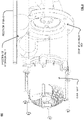
- FIG. 9 is a diagram illustrating another example 900 of a reservoir for use within a thermal system in accordance with the present invention.
- This diagram is an alternative example 900 of a reservoir that includes a 1 st section of the reservoir 206-13 and a 2 nd section of the reservoir 206-14 that, when implemented in conjunction with one another, form a reservoir. Note that the connectivity, coupling, joining, etc.
- a reservoir interface at which the 1 st section of the reservoir 206-13 and the 2 nd section of the reservoir 206-14 are joined may be achieved using any desired means (e.g., a weld interface, a glued interface, a hot molded interface, a hot plate weld interface, thermal weld interface, a sonic weld interface, an ultrasonic weld interface, etc. and/or any other means by which two sections of a reservoir may be joined together).
- a weld interface e.g., a weld interface, a glued interface, a hot molded interface, a hot plate weld interface, thermal weld interface, a sonic weld interface, an ultrasonic weld interface, etc. and/or any other means by which two sections of a reservoir may be joined together.
- the reservoir includes a number of interfaces at which various components may be implemented to operate cooperatively with the reservoir and the thermal system of which the reservoir is part.
- a component 320-12 e.g., a pump
- a component 320-13 e.g., another pump
- the component 320-12 e.g., pump
- the component 320-13 e.g., another pump
- a component 320-14 (e.g., a multi-path valve that is internally mounted) is configured to be mounted to, connect to, and/or couple to the 2 nd section of the reservoir 206-14 based on a component mounting interface 610-4.
- the component 320-14 e.g., a multi-path valve
- the component 320-14 is mounted internally to the reservoir and also serves, at least partially, as a component mounting interface on which another component 320-15 (e.g., an actuator) is mounted.
- the component 320-12 (e.g., a multi-path valve) mounted internally to an opening, orifice, etc.
- the component 320-15 (e.g., an actuator) is mounted to and interacts, during operation, with the component 320-12 (e.g., a multi-path valve) as well as based on the component mounting interface 610-4.
- the component 320-15 e.g., an actuator
- a component 320-15 e.g., a chiller
- a component 320-15 is configured to be mounted to, connect to, and/or couple to the 1 st section of the reservoir 206-13 based on a component mounting interface 610-5.
- the 2 nd section of the reservoir 206-14 includes multiple hose interfaces (e.g., hose interface 340-10).
- the hose interface 340-10 is of a different type and form than other hose interfaces described herein (e.g., hose interfaces 340-8 and 340-9).
- the hose interface 340-9 and the hose interface 340-10 compare favorably, and from other perspectives, the hose interface 340-9 and the hose interface 340-10 compare unfavorably.
- the hose interface 340-9 and the hose interface 340-10 provide interfaces by which hoses may be connected and/or coupled to a portion of a reservoir to operate cooperatively with the reservoir.
- the hose interface 340-10 included integrated elements (e.g., barbs, non-uniformities, etc.) that are implemented to permit a hose to interface thereto without requiring any hoses, clamps, etc. In some examples, such a hose to hose interface coupling, connection, etc.
- a quick connect e.g., such as a quick connect that includes one or more of o-rings, snap-rings, and/or other elements known in the art to facilitate coupling, connectivity, etc. of the hose to the hose interface).
- the various component mounting interface may be of various types, shapes, forms, etc. As may be seen, different types of hose interfaces may be included within one or more portions of a reservoir. Also, different types of component mounting interfaces may be included within one or more portions of a reservoir based on the shape, properties, function, purpose, and/or characteristics of a given component. As can be seen in this diagram, different types of component mounting interfaces are included to facilitate the mounting of different types of components to the various portions of the reservoir.
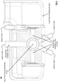
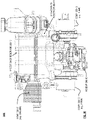
- FIG. 10 is a diagram illustrating another perspective 1000 of the example of the reservoir of FIG. 9 .
- This other perspective 1000 shows an assembled view showing the 1 st section of the reservoir 206-13 and the 2 nd section of the reservoir 206-14 implemented in conjunction with one another forming the reservoir.
- Certain components are visible as being implemented on, mounted to, connected to, and/or coupled to the various portions of the reservoir.
- the component 320-15 e.g., the chiller
- the chiller is shown as being implemented on, connected to, and/or coupled the 1 st section of the reservoir 206-13.
- the component 320-12 (e.g., the pump) and the component 320-13 (e.g., the other pump) are shown as being implemented on, mounted to, connected to, and/or coupled the 2 nd section of the reservoir 206-14.
- multiple hose interfaces (e.g., hose interface 340-10) are also shown in this assembled view of the reservoir.
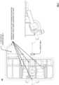
- FIG. 11A is a diagram illustrating a side view 1101 of the perspective of the example of the reservoir of FIG. 9 and FIG. 10 .
- This side view 1101 shows the assembled view showing the 1 st section of the reservoir 206-13 and the 2 nd section of the reservoir 206-14.
- This side view 1101 also shows component 320-15 (e.g., the chiller) as being implemented on, mounted to, connected to, and/or coupled the 1 st section of the reservoir 206-13 and the component 320-12 (e.g., the pump) as being implemented on, mounted to, connected to, and/or coupled to the 2 nd section of the reservoir 206-14.
- component 320-15 e.g., the chiller
- component 320-12 e.g., the pump
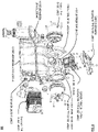
- FIG. 11B is a diagram illustrating another side view 1102 of the perspective of the example of the reservoir of FIG. 9 and FIG. 10 .
- This side view 1102 also shows the assembled view showing the 1 st section of the reservoir 206-13 and the 2 nd section of the reservoir 206-14, yet from a different perspective.
- This side view 1102 also shows component 320-12 (e.g., the other pump) as being implemented with, connected to, and/or coupled to the 2 nd section of the reservoir 206-14.
- component 320-12 e.g., the other pump
Landscapes
- Engineering & Computer Science (AREA)
- Chemical & Material Sciences (AREA)
- Manufacturing & Machinery (AREA)
- General Chemical & Material Sciences (AREA)
- Electrochemistry (AREA)
- Chemical Kinetics & Catalysis (AREA)
- Mechanical Engineering (AREA)
- Transportation (AREA)
- Power Engineering (AREA)
- Combustion & Propulsion (AREA)
- Automation & Control Theory (AREA)
- Life Sciences & Earth Sciences (AREA)
- Sustainable Development (AREA)
- Sustainable Energy (AREA)
- Cooling Or The Like Of Electrical Apparatus (AREA)
- Cooling, Air Intake And Gas Exhaust, And Fuel Tank Arrangements In Propulsion Units (AREA)
- Secondary Cells (AREA)
- Arrangement Or Mounting Of Propulsion Units For Vehicles (AREA)
- Electric Propulsion And Braking For Vehicles (AREA)
Description
- The present disclosure relates generally to thermal management systems such as those that are implemented within vehicles.
- Electric motors can generate considerable heat, especially in the traction motor of a vehicle where size and weight constraints are coupled with the need for high power output. Electric motor overheating causes the motor winding insulation to deteriorate quickly. For every 10-degree Celsius rise in electric motor temperature, insulation life is cut in half. Another issue caused by overheating is that permanent magnets in the rotor lose their magnetic properties as they overheat, resulting in a loss of efficiency. For induction motors, an increase in temperature of the copper windings reduces efficiency of the induction motor-copper electrical resistivity increases 4% for every 10-degree Celsius temperature increase. Thus, it is important to cool the internal motor components (e.g., rotor) as well as the outer motor components (e.g., case, stator). The architecture of the electric motor cooling system must operate efficiently with large variations in ambient operating environment as the electric motor may be subjected to a wide range of ambient temperatures, humidity levels, and/or dust/dirt levels.
- The prior art solutions for thermal systems that perform cooling of various components within a vehicle typically include a coolant reservoir that stores coolant of some desired material that then gets passed via hosing to one or more other components within the vehicle. For example, the coolant reservoir is typically located in one location and is interconnected with one or more other components that are separately located via hosing. Such a prior art implementation provides a significant number of connections, hosing, fasteners, etc. and also provides a large number of possible failure points within the overall thermal system.
- In addition, such a prior art implementation can be very time-consuming and laborintensive when assembling a vehicle that includes such a prior art thermal system. For example, a prior art coolant reservoir assembly will typically require mounting of multiple discrete components to the vehicle, the interconnection of multiple electrical connectors for different components, and the connection of multiple hoses and hose clamps to route the flow of coolant to these various components located in different respective locations. The multi-faceted construction and assembly of these parts is time-intensive and gives rise to multiple points of potential failure in hoses, clamps, electrical connections, etc.. Furthermore, the need to weld the typical coolant bottle housing portions often necessitates multiple weld points along the inlet and outlet channels of the structure, such that the weld lines and residue from the welding process are introduced into the flow channels of the inlets and outlets, compromising the smoothness and fluidity of the channel and reducing efficiency of liquid flow through the channel.
- Typical examples of the prior art are shown in
US 2009/151903 ,US 2007/044938 , andUS 2012/168118 .US 2009/0151903 A1 discloses a coolant reservoir tank for fuel-cell vehicle which includes a tank body, inlet and outlet ports, and a pipe to the reservoir tank and connected to the inlet and outlet ports via clamps or similar hose connectors.US 2012/0168118 A1 describes a coolant flow control management system including an integrated pump coolant flow control and heat exchange device for delivering engine coolant to and from an engine. - The invention provides a reservoir according to
claim 1. Embodiments are defined in the dependent claims. -
-
FIG. 1 is a diagram illustrating an example of basic components of a battery powered electric vehicle. -
FIG. 2 is a diagram illustrating an example of components of a drive motor cooling system and a battery heating system, both constructed and operating according to a disclosed embodiment. -
FIG. 3A is a diagram illustrating an example of a reservoir for use within a thermal system in accordance with the present invention. -
FIG. 3B is a diagram illustrating another example of a reservoir for use within a thermal system in accordance with the present invention. -
FIG. 3C is a diagram illustrating another example of a reservoir for use within a thermal system in accordance with the present invention. -
FIG. 3D is a diagram illustrating another example of a reservoir for use within a thermal system in accordance with the present invention. -
FIG. 4A is a diagram illustrating another example of a reservoir for use within a thermal system in accordance with the present invention. -
FIG. 4B is a diagram illustrating another example of a reservoir for use within a thermal system in accordance with the present invention. -
FIG. 4C is a diagram illustrating another example of a reservoir for use within a thermal system in accordance with the present invention. -
FIG. 4D is a diagram illustrating another example of a reservoir for use within a thermal system in accordance with the present invention. -
FIG. 5 is a diagram illustrating an example of a portion of a reservoir for use within a thermal system in accordance with the present invention. -
FIG. 6 is a diagram illustrating another example of a portion of a reservoir for use within a thermal system in accordance with the present invention. -
FIG. 7 is a diagram illustrating another example of a portion of a reservoir for use within a thermal system in accordance with the present invention. -
FIG. 8 is a diagram illustrating another example of a portion of a reservoir for use within a thermal system in accordance with the present invention. -
FIG. 9 is a diagram illustrating another example of a reservoir for use within a thermal system in accordance with the present invention. -
FIG. 10 is a diagram illustrating another perspective of the example of the reservoir ofFIG. 9 . -
FIG. 11A is a diagram illustrating a side view of the perspective of the example of the reservoir ofFIG. 9 andFIG. 10 . -
FIG. 11B is a diagram illustrating another side view of the perspective of the example of the reservoir ofFIG. 9 andFIG. 10 . -
FIG. 1 illustrates an example 100 of basic components of a battery powered electric vehicle (electric vehicle). The electric vehicle includes at least one drive motor (traction motor) 102A and/or 102B, at least onegear box 104A and/or 104B coupled to acorresponding drive motor 102A and/or 102B, abattery 106 andelectronics 108. Generally, thebattery 106 provides electricity to the power electronics of the electric vehicle and to propel the electric vehicle using thedrive motor 102A and/or 102B. The electric vehicle includes a large number of other components that are not described herein but known to one of ordinary skill. While the construct of the electric vehicle ofFIG. 1 is shown to have four wheels, differing electric vehicles may have fewer or more than four wheels. Further, differing types of electric vehicles may incorporate the inventive concepts described herein, including motor cycles, aircraft, trucks, boats, train engines, among other types of vehicles. - Various operational issues with the electric vehicle are described herein in conjunction with various embodiments. One of these operational issues relates to the cooling of the
drive motor battery 106. Still another of these operational issues relates to protection of thedrive motor FIG. 1 . Common numbering may be used to refer to components identified in further FIGs. described herein. -
FIG. 2 illustrates an example 200 of components of a drive motor cooling system and a battery heating system, both constructed and operating according to a disclosed embodiment. The drive motor cooling system includes a drive motorfluid pump system 202 having a drivemotor fluid pump 204, acoolant reservoir 206 andelectronics 208. In the illustrated embodiment, the fluid is oil. The drivemotor fluid pump 204 pumps fluid between thedrive motor 102A and/or 102B, thefluid reservoir 206, and aheat exchanger 210. In one embodiment, the heat exchanger exchanges heat from the oil based drive motor fluid with water or alcohol based coolant and routes the water or alcohol based coolant to aradiator 212 for cooling. In general, any desired liquid medium for coolant may be used in any desired embodiment. The heat exchanger may include another pump to circulate the water or alcohol based coolant. Theheat exchanger 210, in the illustrated embodiment couples tocoolant tubes 214 adjacent to or running through the components of thebattery 106. In other embodiments, the drivemotor fluid pump 204 may couple directly to thecoolant tubes 214 of thebattery 106 and/or to theradiator 212. The drivemotor fluid pump 204 is controlled byelectronics 208, which may include a digital computer and other related components. The drivemotor fluid pump 204 may include control valves to control flow of fluid between thedrive motor 102A and/or 102B, thereservoir 206, and the heat exchanger 210 (andbattery 106coolant tubes 214 in other embodiments). Theheat exchanger 210 may also include valves to direct the flow of coolant to thebattery 106coolant tubes 214 and to theradiator 212, under control ofelectronics 208 in some embodiments. - Various examples of reservoirs for use in thermal systems are provided herein. Any of these various examples of reservoirs may be used within various applications. Some applications include those tailored for any desired example of a battery powered electric vehicle (electric vehicle) such as described with respect to
FIG. 1 and may be tailored for any desired example of a drive motor cooling system and/or a battery heating system as described with respect toFIG. 2 . Such examples of reservoirs may be viewed as being part of an integrated coolant bottle assembly. For example, such a reservoir may be viewed as a bottle, a coolant bottle, etc. that is a portion of an integrated coolant bottle assembly that allows for one or more components to be coupled to, attached to, and/or connected to the reservoir. In addition, the reservoir itself may be fabricated such that one or more integrated channels are included within one or more portion of the reservoir that allow for one or more pathways between the one or more components, one or more hose interfaces, etc. -
FIG. 3A is a diagram illustrating an example 301 of a reservoir for use within a thermal system in accordance with the present invention. In general, such a reservoir 206-1 include an input/output port 310-1 via which some liquid medium (e.g., any desired type of fluid such as coolant liquid, anti-freeze, water, an alcohol based agent, a heating agent, etc. and/or any desired combination of any such liquid mediums) may be added to the reservoir 206-1 and/or removed there from. Such an input/output port 310-1 may include a cap or some secured mechanism by which the liquid medium is prevented from escaping from the reservoir 206-1 and to ensure other elements do not enter the reservoir 206-1. The reservoir 206-1 is designed such that one or more components that operate in accordance with the thermal system (e.g., shown as components 320-1 and 320-2). Examples of components may include anything that is part of the thermal system and/or anything that is part of a system in which the thermal system is situated. For example, considering the example of a thermal system implemented within a vehicle (e.g., battery powered electric vehicle (electric vehicle)), examples of such components may include any one or more of a pump (e.g., a battery pump, a powertrain pump, etc.), a chiller, a heater, a filter, an aerator, a fan, a radiator, etc. and/or any other components known in the art as related to such thermal systems. - In this example 301, the reservoir 206-1 includes one or more interfaces at which one or more of the components 320-1 and 320-2 may be coupled, attached, and/or connected to the reservoir 206-1. In addition, the reservoir 206-1 may optionally include one or more hose interfaces 340-1 at which one or more hoses may be coupled to, attached to, and/or connected to the reservoir 206-1. The reservoir 206-1 allows for both integration of one or more components as well as for hose-based interfacing of one or more other components. Also, the reservoir 206-1 include an integrated channel 330-1 via which the liquid medium is transported between the components 320-1 and 320-2. The integrated channel 330-1 is formed within at least one portion of the reservoir 206-1 during its fabrication, molding, generation, etc. That is to say, during the manufacturing of the reservoir 206-1, the integrated channel 330-1 is formed therein and between interfaces at which the components 320-1 and 320-2 may be connected. Then, when one or both of the components 320-1 and 320-2 is/are interfaced with the reservoir 206-1, the integrated channel 330-1 provides interconnection between the components 320-1 and 320-2.
- In some examples, such integrated channels may be formed based on hollowed using slides that are pulled along the axis of a cylindrical channel. Such a technique may be used to form multiple integrated channels (e.g., flow channels) in several orientations within a given portion of a reservoir. In addition, such construction may be used to form integrated tees that would have otherwise required external hoses and fittings.
- By using integrated channels within the body of the reservoir, the reservoir itself includes various integrated channels that operate to direct the flow of the liquid medium directly into various components that are integrated with the coolant bottle (e.g., such as a chiller, a battery pump, a powertrain pump, etc.). This will obviate any need to attach these components separately to the vehicle and to attach these components via hoses and clamps to the reservoir. Instead, a unitary reservoir design structure can be formed to generate an integrated coolant bottle assembly, and such an integrated coolant bottle assembly can then be bolted to and installed within a vehicle relatively easily (e.g., using as few as two bolts in some examples). Also, in some implementations, such an integrated coolant bottle assembly can be connected to such a vehicle's electrical system using a single electrical connector that includes the respective electrical leads therein that correspond to each of the pertinent electrical components as opposed to requiring time-consuming connection of each respective electrical component via a separate respective electrical connector. Moreover, in other implementations, temperature sensors are also integrated into specific integrated channels (e.g., flow channels) at locations where it is desired to obtain measurements of the fluid medium. Such integration of temperature sensors directly into the ports of the coolant bottle eliminates the need for additional external parts, seals and clamps.
-
FIG. 3B is a diagram illustrating another example 302 of a reservoir for use within a thermal system in accordance with the present invention. The reservoir 206-2 includes an input/output port 310-2. Also, the reservoir 206-2 has integrated therewith components 320-3, 320-3, 320-5, and 320-6 that are attached thereto. Moreover, the reservoir 206-2 has integrated therewith apump 312 and achiller 314. Note that different embodiments of reservoirs may be of different sizes, shapes, forms, etc. and may include different respective numbers and types of components integrated therewith as may be desired and/or needed within a particular implementation and design of a thermal system. In addition, reservoir 206-2 optionally includes hose interfaces 340-2 and 340-3. As desired, any number of integrated channels may be included within a portion of the reservoir 206-2. For example, an integrated channel 330-2 provides a pathway for the liquid medium betweenchiller 314 and component 320-5. Other integrated channels are also shown as providing respective pathways between various elements associated with the reservoir 206-2 in the diagram. Also, note that the manner by which any of thepump 314,chiller 314, and components 320-3 to 320-5 interface to, connect to, couple to, etc. the reservoir 206-2 may be varied. For example, the component 320-3 is shown as be associated with and interfaces to the reservoir 206-2 at a lower end portion of the reservoir 206-2. Thepump 312 andchiller 314 are shown as be associated with and interfaces to the reservoir 206-2 at upper respective portions of the reservoir 206-2. The component 320-6 is shown as being substantially centrally associated with the reservoir 206-2 and being provided integrated pathways to multiple respective other components (e.g., components 320-4 and 320-5 and pump 312 and optionally to hose interface 340-3). -
FIG. 3C is a diagram illustrating another example 303 of a reservoir for use within a thermal system in accordance with the present invention. The reservoir 206-3 includes an input/output port 310-3 and at least two components 330-7 and 330-8. In this example 303, note that reservoir 206-3 includes a recess into which the component 330-8 fits when interfaced to the reservoir 206-3. In general, a reservoir designed in accordance with the principles herein may include any number of recesses, orifices, faces, ports, etc. that allow one or more components to interface to the reservoir. - In this example 303, the reservoir 206-3 itself includes an integrated channel 330-3 that provides a pathway for the liquid medium between components 330-7 and 330-8. In general, a particular design of a reservoir can include any one or more types of interfaces that are suitably designed and tailored to allow for the coupling, connection, etc. of any desired types of components to the reservoir 206-3. As with other examples herein, note that any one or more hose interfaces may also be included within a given design of a reservoir. A designer has total flexibility to decide how many components to integrate to the reservoir design and how many, if any, are to interact with the reservoir via hose interfaces.
-
FIG. 3D is a diagram illustrating another example 304 of a reservoir for use within a thermal system in accordance with the present invention. A reservoir 206-4 includes a first section of reservoir 206-4 and a second section of reservoir 206-4 that are joined together via areservoir interface 304 to form the reservoir 206-4. For example, the connectivity, coupling, joining, etc. at thereservoir interface 304 may be achieved using any desired means (e.g., a weld interface, a glued interface, a hot molded interface, a hot plate weld interface, thermal weld interface, a sonic weld interface, an ultrasonic weld interface, etc. and/or any other means by which two sections of a reservoir may be joined together). Note that different means of joining the respective sections of a reservoir may be used based on various considerations including the material(s) used to construct the reservoir. Regardless of the particular material(s) used to construct the reservoir and regardless of the manner by which the respective sections of the reservoir are joined together, such a reservoir may be designed to include any desired number of sections (e.g., 2, 3, 4, or any positive integer greater than 1). In general, a reservoir as designed herein can include multiple sections (e.g., two halves) of the reservoir that are manufactured with integrated channels (e.g., flow channels) that are formed by the intersection of the core and cavity of the mold(s) of the respective sections of the reservoir. - From certain perspectives, the reservoir of this diagram may be viewed as including a first section and a second section. The second section is joined to the first section at a reservoir interface thereby forming a reservoir that is configured to facilitate at least one of storage or flow of a liquid medium. Also, in some examples, the first section or the second section includes an integrated channel that provides a pathway for the flow of the liquid medium.
- In some examples, the component interface is also configured to facilitate connection of a component thereto, and the integrated channel provides the pathway for the flow of the liquid medium to or from the component interface. Also, note that the component may include any of a number of different types of components including any one of a pump, a battery pump, a powertrain pump, a chiller, a heater, a filter, an aerator, a fan, a radiator, etc. and/or any other components known in the art as related to such thermal systems.
- In addition, in some examples, the reservoir includes a first component interface configured to facilitate connection of a first component thereto as well as a second component interface configured to facilitate connection of a second component thereto. In some situations, the integrated channel provides the pathway for the flow of the liquid medium from the first component interface to the second component interface.
- Also, in other examples, the reservoir includes a hose interface configured to facilitate connection of a hose to transport the liquid medium to or to receive the liquid medium from another component that is located remotely from the reservoir and coupled to the reservoir by the hose. In even other examples, the reservoir includes a recess configured to facilitate connection of a component. In some implementations, the integrated channel provides the pathway for the flow of the liquid medium to or from the recess.
- Note that such a reservoir as described with respect to this diagram and/or any other diagram, example, embodiment, etc. herein and/or their equivalents may be implemented in a variety of applications including a drive motor cooling system and/or a battery heating system of a battery powered electric vehicle.
-
FIG. 4A is a diagram illustrating another example 401 of a reservoir for use within a thermal system in accordance with the present invention. A reservoir 206-5 includes a first section of reservoir 206-5 and a second section of reservoir 206-6 that are joined together at a first reservoir interface 304-1 to form part of the reservoir 206-5. The reservoir 206-5 includes another section of reservoir 206-5 that is joined to the second section of reservoir 206-6 at a second reservoir interface 304-2 to form another part of the reservoir 206-5. In general, any number (e.g., two or more) of different sections of a reservoir may be joined together at any desired number of reservoir interfaces (e.g., a first reservoir interface 304-1, a second reservoir interface 304-2, and so on to an nth reservoir interface 304-3). -
FIG. 4B is a diagram illustrating another example 402 of a reservoir for use within a thermal system in accordance with the present invention. A reservoir 206-6 includes multiple section of reservoir 206-6 (e.g., including a first section of reservoir 206-6) that are joined at various reservoir interfaces 304-4 and 304-5. This diagram shows an example of four substantially similarly-sized sections of the reservoir 206-6. -
FIG. 4C is a diagram illustrating another example 403 of a reservoir for use within a thermal system in accordance with the present invention. A reservoir 206-7 includes multiple section of reservoir 206-7 (e.g., including a first section of reservoir 206-7) that are joined at various reservoir interfaces (e.g., including reservoir interface 304-6). This diagram shows an example of three sections of the reservoir 206-7 that are of different respective sizes. -
FIG. 4D is a diagram illustrating another example 404 of a reservoir for use within a thermal system in accordance with the present invention. A reservoir 206-8 includes two respective sections that are joined together and form a channel at the reservoir interface 304-7 between the two respective sections. An integrated channel 330-3 is formed at the interface between the two respective sections of the reservoir 206-8 and provides a pathway for the liquid medium to be transported between components 330-9 and 330-10. - A first portion of the integrated channel 330-3 is within a first or top section of the reservoir 206-8, and a second portion of the integrated channel 330-3 is within the second or bottom section of the reservoir 206-8. The sections of the reservoir 206-8 are fabricated such that when they are joined together, the integrated channel 330-3 is formed at the reservoir interface 304-7 where the first portion of the integrated channel 330-3 complementarily aligns with second portion of the integrated channel 330-3 at the reservoir interface 304-7. Note that any desired proportions of the integrated channel 330-3 may be fabricated using the two respective sections of the reservoir 206-8 (e.g., one-half in each section, a fourth in one section and three-fourths in the other section, X% in in one section and (1-X)% in the other section wherein X is any desired number between 0 and 100). In other examples, note that one or more integrated channels may be formed at a reservoir interface, and one or more other integrated channels may be included within one or more sections of a reservoir. For example, during manufacturing of a reservoir, the integrated channels (e.g., flow paths) can be formed by creating recesses within respective portions of the reservoir structures, forming smooth cylindrical or tubular flow channels, with no weld points located along the channels themselves.
-
FIG. 5 is a diagram illustrating an example 500 of a portion of a reservoir for use within a thermal system in accordance with the present invention. This diagram shows a first section of reservoir 206-9 that includes multiple hose interfaces (e.g., hose interfaces 340-4, 340-5, 340-6, and 340-7) and multiple integrated channels (e.g., integrated channels 330-4, 330-5, and 330-6). Also, this first section of reservoir 206-9 includes a multi-pathvalve mounting interface 510 at which a multi-path valve may be interfaced with this first section of reservoir 206-9. In some examples, such a multi-path valve is included in within the multi-pathvalve mounting interface 510 that provides for a smooth, unobstructed and integrated multi-path valve to be interfaced within the first section of reservoir 206-9. In some examples, the valve stem of such a multi-path valve is uniquely shaped, and its orientation can be manipulated to achieve desired flow configurations, or combinations of flow configurations, including blend modes. Using the valve stem of such a multi-path valve allows the coolant loops to be combined in parallel, or operated in series mode, as well as allowing certain thermal components to be bypassed when not required. - Note that various reservoirs may have different shapes, forms, etc. and may include different types of mounting interfaces to allow for different types of components to be mounted onto the reservoir.
-
FIG. 6 is a diagram illustrating another example 600 of a portion of a reservoir for use within a thermal system in accordance with the present invention. This diagram shows a first section of reservoir 206-10 that includes at least one hose interface (e.g., hose interface 340-8), at least one integrated channel (e.g., integrated channel 330-7), and at least one component mounting interface (e.g., component mounting interface 610). In addition, this diagram shows a reservoir interface 304-8 at which the first section of reservoir 206-10 may be joined with at least one other section of reservoir 206-10. In some examples, note that the example 600 that shows the first section of reservoir 206-9 corresponds to another perspective view of the first section of reservoir 206-9 in the example 500 ofFIG. 5 . -
FIG. 7 is a diagram illustrating another example 700 of a portion of a reservoir for use within a thermal system in accordance with the present invention. This diagram shows a first section of reservoir 206-11 that includes at least one hose interface (e.g., hose interface 340-9). Also, this diagram shows multiple reservoir interfaces 304-9 including the section's perimeter edge and internal faces, edges, surfaces, etc. For example, note that the first section of reservoir 206-11 may be joined to another section of reservoir 206-11 not only along the section's perimeter edge, but also at one or more additional internal faces, edges, surfaces, etc. Note that such internal faces, edges, surfaces, etc. may be designed so that they substantially or approximately align with other internal faces, edges, surfaces, etc. or another section of reservoir 206-11 when the respective sections of reservoir 206-11 are joined together. In some examples, note that the example 700 that shows the first section of reservoir 206-11 corresponds to another perspective view of the first section of reservoir 206-9 in the example 500 ofFIG. 5 and/or of the first section of reservoir 206-10 in the example 600 ofFIG. 6 . In some examples, note that the hose interface 340-9 corresponds to another perspective view of hose interface 340-4 as shown inFIG. 5 . -
FIG. 8 is a diagram illustrating another example 800 of a portion of a reservoir for use within a thermal system in accordance with the present invention. This diagram shows a first section of reservoir 206-12 that includes at least one component mounting interface that allows for at least one component to interface to, connect to, couple to, etc. the reservoir 206-12. For example, the first section of reservoir 206-12 includes component mounting interface 610-1 that allows for component 320-11 to be mounted thereon. - Note also that any of the various components described herein may be interfaced to, connects to, couples to, etc. a particular section of a reservoir before the reservoir (and its accompanying components) are installed within a thermal system such as may be included within a vehicle (e.g., battery powered electric vehicle (electric vehicle), a conventionally-gas powered vehicle, a diesel fuel powered vehicle, a natural gas powered vehicle, a solar powered vehicle, and/or any other type of vehicle).
- In addition, note that a reservoir designed in accordance with such an integrated coolant bottle assembly in accordance with the principles described herein may be included within any desired thermal system application. Some implementation examples include vehicles and may include battery powered electric vehicles (electric vehicles). However, other implementation examples include electric power generators that may include motor-based systems (e.g., stationary/fixed location generators, mobile generators, etc.). Even other implementation examples include any type of components that may be included within physical plant installations (e.g., power plants, oil refineries, etc.) such as pumps, scrubbers, mixers, blowers, vacuums, etc. and/or any other components implemented within such applications and/or installations. In general, any thermal system that includes one or more reservoirs may be adapted with an integrated coolant bottle assembly based on the principles described herein and in accordance with the various aspects, embodiments, and/or examples of the invention.
- Note that certain of the following several diagrams may be viewed in cooperation with one another as they are based on different views, perspectives, etc. of an alternative configuration of a reservoir in accordance with various aspects, embodiments, and/or examples of the invention. For example, this alternative configuration of a reservoir that, when implemented with various components, etc., includes different respective sections of the reservoir (e.g., at least a 1st and 2nd section of the reservoir), a chiller, multiple pumps, a multi-path valve (e.g., 5-way valve), an actuator configured to operate cooperatively with the multi-path valve, among other elements.
-
FIG. 9 is a diagram illustrating another example 900 of a reservoir for use within a thermal system in accordance with the present invention. This diagram is an alternative example 900 of a reservoir that includes a 1st section of the reservoir 206-13 and a 2nd section of the reservoir 206-14 that, when implemented in conjunction with one another, form a reservoir. Note that the connectivity, coupling, joining, etc. at a reservoir interface at which the 1st section of the reservoir 206-13 and the 2nd section of the reservoir 206-14 are joined may be achieved using any desired means (e.g., a weld interface, a glued interface, a hot molded interface, a hot plate weld interface, thermal weld interface, a sonic weld interface, an ultrasonic weld interface, etc. and/or any other means by which two sections of a reservoir may be joined together). - The reservoir includes a number of interfaces at which various components may be implemented to operate cooperatively with the reservoir and the thermal system of which the reservoir is part. For example, a component 320-12 (e.g., a pump) is configured to be mounted to, connect to, and/or couple to the 2nd section of the reservoir 206-14 based on a component mounting interface 610-2. A component 320-13 (e.g., another pump) is configured to be mounted to, connect to, and/or couple to the 2nd section of the reservoir 206-14 based on a component mounting interface 610-3. In an example of operation and implementation, the component 320-12 (e.g., pump) and the component 320-13 (e.g., another pump) operate to facilitate the flow of coolant at different respective rates (e.g., based on control signaling from electronics of a coolant system) within the overall coolant system.
- As some other examples, a component 320-14 (e.g., a multi-path valve that is internally mounted) is configured to be mounted to, connect to, and/or couple to the 2nd section of the reservoir 206-14 based on a component mounting interface 610-4. Note that the component 320-14 (e.g., a multi-path valve) is mounted internally to the reservoir and also serves, at least partially, as a component mounting interface on which another component 320-15 (e.g., an actuator) is mounted. For example, the component 320-12 (e.g., a multi-path valve) mounted internally to an opening, orifice, etc. of the 2nd section of the reservoir 206-14, and the component 320-15 (e.g., an actuator) is mounted to and interacts, during operation, with the component 320-12 (e.g., a multi-path valve) as well as based on the component mounting interface 610-4. In an example of operation and implementation, the component 320-15 (e.g., an actuator) operates to place the component 320-12 (e.g., a multi-path valve) into different respective configurations (e.g., based on control signaling from electronics of a coolant system) to direct the flow of coolant in different respective directions within the overall coolant system.
- This particular configuration shows how one or more components may operate cooperatively to serve as a component mounting interface in conjunction with the reservoir. Also, a component 320-15 (e.g., a chiller) is configured to be mounted to, connect to, and/or couple to the 1st section of the reservoir 206-13 based on a component mounting interface 610-5. In addition, the 2nd section of the reservoir 206-14 includes multiple hose interfaces (e.g., hose interface 340-10). Note that the hose interface 340-10 is of a different type and form than other hose interfaces described herein (e.g., hose interfaces 340-8 and 340-9). For example, from certain perspectives, the hose interface 340-9 and the hose interface 340-10 compare favorably, and from other perspectives, the hose interface 340-9 and the hose interface 340-10 compare unfavorably. For example, the hose interface 340-9 and the hose interface 340-10 provide interfaces by which hoses may be connected and/or coupled to a portion of a reservoir to operate cooperatively with the reservoir. However, the hose interface 340-10 included integrated elements (e.g., barbs, non-uniformities, etc.) that are implemented to permit a hose to interface thereto without requiring any hoses, clamps, etc. In some examples, such a hose to hose interface coupling, connection, etc. is implemented using a quick connect (e.g., such as a quick connect that includes one or more of o-rings, snap-rings, and/or other elements known in the art to facilitate coupling, connectivity, etc. of the hose to the hose interface).
- In general, note also that the various component mounting interface may be of various types, shapes, forms, etc. As may be seen, different types of hose interfaces may be included within one or more portions of a reservoir. Also, different types of component mounting interfaces may be included within one or more portions of a reservoir based on the shape, properties, function, purpose, and/or characteristics of a given component. As can be seen in this diagram, different types of component mounting interfaces are included to facilitate the mounting of different types of components to the various portions of the reservoir.
-
FIG. 10 is a diagram illustrating anotherperspective 1000 of the example of the reservoir ofFIG. 9 . Thisother perspective 1000 shows an assembled view showing the 1st section of the reservoir 206-13 and the 2nd section of the reservoir 206-14 implemented in conjunction with one another forming the reservoir. Certain components are visible as being implemented on, mounted to, connected to, and/or coupled to the various portions of the reservoir. For example, the component 320-15 (e.g., the chiller) is shown as being implemented on, connected to, and/or coupled the 1st section of the reservoir 206-13. The component 320-12 (e.g., the pump) and the component 320-13 (e.g., the other pump) are shown as being implemented on, mounted to, connected to, and/or coupled the 2nd section of the reservoir 206-14. In addition, as can be seen in the diagram, multiple hose interfaces (e.g., hose interface 340-10) are also shown in this assembled view of the reservoir. -
FIG. 11A is a diagram illustrating aside view 1101 of the perspective of the example of the reservoir ofFIG. 9 andFIG. 10 . Thisside view 1101 shows the assembled view showing the 1st section of the reservoir 206-13 and the 2nd section of the reservoir 206-14. Thisside view 1101 also shows component 320-15 (e.g., the chiller) as being implemented on, mounted to, connected to, and/or coupled the 1st section of the reservoir 206-13 and the component 320-12 (e.g., the pump) as being implemented on, mounted to, connected to, and/or coupled to the 2nd section of the reservoir 206-14. -
FIG. 11B is a diagram illustrating anotherside view 1102 of the perspective of the example of the reservoir ofFIG. 9 andFIG. 10 . Thisside view 1102 also shows the assembled view showing the 1st section of the reservoir 206-13 and the 2nd section of the reservoir 206-14, yet from a different perspective. Thisside view 1102 also shows component 320-12 (e.g., the other pump) as being implemented with, connected to, and/or coupled to the 2nd section of the reservoir 206-14.
Claims (10)
- A reservoir configured for use in a thermal system of a vehicle, the reservoir (206) comprising:a first section; anda second section that is joined to the first section at a reservoir interface (304) thereby forming a reservoir that is configured to allow at least one of storage or flow of a liquid medium, wherein the first section includes multiple integrated channels (330) that provide multiple pathways for the flow of the liquid medium, the multiple integrated channels (330) formed in a body of the first section of the reservoir;wherein the first section further comprises:multiple component interfaces configured to allow attachment of multiple components (320) to the reservoir, wherein the integrated channels (330) provide the pathways for the flow of the liquid medium to or from the component interfaces to allow the components to operate cooperatively with the reservoir and the thermal system; anda hose interface (340) configured to allow coupling of a hose to the reservoir to transport the liquid medium to or to receive the liquid medium from another component that is located remotely from the reservoir and coupled to the reservoir by the hose.
- The reservoir of claim 1, wherein each of the component interfaces is configured to allow attachment of one of the components to the reservoir without the need of an intermediate hose.
- The reservoir of claim 1 or 2, wherein each of the component interfaces is configured to allow mounting of one of the components to the reservoir so as to obviate any need to attach the component separately to a vehicle.
- The reservoir of claim 1, wherein the first section further comprises:
a recess configured to allow connection of at least one of the components (330-8), wherein the integrated channels provide the pathway for the flow of the liquid medium to or from the recess. - The reservoir of claim 1, wherein the second section is joined to the first section at the reservoir interface that is a weld interface, a glued interfaced, a hot molded interface, a hot plate weld interface, thermal weld interface, a sonic weld interface, or an ultrasonic weld interface.
- The reservoir of claim 1, wherein the first section includes a first portion of another integrated channel that provides another pathway for the liquid medium, and the second section includes a second portion of another integrated channel provides the another pathway for the liquid medium, wherein the another integrated channel is formed along at least a portion of the reservoir interface where the first section is joined to the second section and where the first portion of the another integrated channel complementarily aligns with the second portion of the another integrated channel.
- The reservoir of one of the preceding claims configured for use in at least one of a drive motor cooling system or a battery heating system of a battery powered electric vehicle, wherein:
the reservoir is configured to facilitate at least one of storage or flow of a liquid medium within the at least one of the drive motor cooling system or the battery heating system of the battery powered electric vehicle. - The reservoir of one of the preceding claims, wherein the integrated channels are formed within the first section of the reservoir during molding of the reservoir.
- The reservoir of claim 8, wherein the integrated channels are formed by creating recesses within the first portion of the reservoir, forming smooth cylindrical or tubular flow channels, with no weld points located along the channels themselves.
- The reservoir of one of the preceding claims, wherein the components include a pump (312), a battery pump, a powertrain pump, a chiller, a heater, a filter, an aerator, a fan, or a radiator.
Priority Applications (1)
| Application Number | Priority Date | Filing Date | Title |
|---|---|---|---|
| EP23153810.9A EP4215395B1 (en) | 2016-06-23 | 2017-06-21 | Integrated coolant bottle assembly |
Applications Claiming Priority (3)
| Application Number | Priority Date | Filing Date | Title |
|---|---|---|---|
| US201662353763P | 2016-06-23 | 2016-06-23 | |
| US15/627,936 US10665908B2 (en) | 2016-06-23 | 2017-06-20 | Heating and cooling reservoir for a battery powered vehicle |
| PCT/US2017/038596 WO2017223232A2 (en) | 2016-06-23 | 2017-06-21 | Integrated coolant bottle assembly |
Related Child Applications (2)
| Application Number | Title | Priority Date | Filing Date |
|---|---|---|---|
| EP23153810.9A Division EP4215395B1 (en) | 2016-06-23 | 2017-06-21 | Integrated coolant bottle assembly |
| EP23153810.9A Division-Into EP4215395B1 (en) | 2016-06-23 | 2017-06-21 | Integrated coolant bottle assembly |
Publications (2)
| Publication Number | Publication Date |
|---|---|
| EP3475112A2 EP3475112A2 (en) | 2019-05-01 |
| EP3475112B1 true EP3475112B1 (en) | 2023-03-15 |
Family
ID=60677987
Family Applications (2)
| Application Number | Title | Priority Date | Filing Date |
|---|---|---|---|
| EP17737108.5A Active EP3475112B1 (en) | 2016-06-23 | 2017-06-21 | Integrated coolant bottle assembly |
| EP23153810.9A Active EP4215395B1 (en) | 2016-06-23 | 2017-06-21 | Integrated coolant bottle assembly |
Family Applications After (1)
| Application Number | Title | Priority Date | Filing Date |
|---|---|---|---|
| EP23153810.9A Active EP4215395B1 (en) | 2016-06-23 | 2017-06-21 | Integrated coolant bottle assembly |
Country Status (8)
| Country | Link |
|---|---|
| US (1) | US10665908B2 (en) |
| EP (2) | EP3475112B1 (en) |
| JP (1) | JP6914972B2 (en) |
| KR (1) | KR102225023B1 (en) |
| CN (1) | CN109562685B (en) |
| HU (1) | HUE062694T2 (en) |
| PL (1) | PL3475112T3 (en) |
| WO (1) | WO2017223232A2 (en) |
Families Citing this family (90)
| Publication number | Priority date | Publication date | Assignee | Title |
|---|---|---|---|---|
| JP6604997B2 (en) * | 2017-07-06 | 2019-11-13 | 本田技研工業株式会社 | Cooling system |
| DE102018102542A1 (en) | 2018-01-29 | 2019-08-01 | Woco Industrietechnik Gmbh | Apparatus for handling fluids and method for producing the same |
| US12364936B2 (en) | 2018-11-16 | 2025-07-22 | Rivian Ip Holdings, Llc | Filter system for coolant |
| KR102600059B1 (en) * | 2018-12-03 | 2023-11-07 | 현대자동차 주식회사 | Thermal management system for vehicle |
| KR102681908B1 (en) * | 2019-06-03 | 2024-07-05 | 한온시스템 주식회사 | Thermal management system |
| US11766915B2 (en) * | 2019-06-03 | 2023-09-26 | Hanon Systems | Heat management system |
| KR102676688B1 (en) * | 2019-06-03 | 2024-06-20 | 한온시스템 주식회사 | Thermal management system |
| CN110126611B (en) * | 2019-06-18 | 2024-10-15 | 广州市利迪汽车用品有限公司 | Water cooling system of bridge and vehicle integrated electric drive system |
| KR102719122B1 (en) * | 2019-06-19 | 2024-10-17 | 현대자동차주식회사 | Integrated thermal management module for vehicle |
| KR102215293B1 (en) * | 2019-07-25 | 2021-02-15 | 현대위아(주) | Valve assembly for integrated thermal management and integrated thermal management module including the same |
| KR102239253B1 (en) * | 2019-08-01 | 2021-04-12 | 현대위아(주) | Valve assembly for integrated thermal management and integrated thermal management module including the same |
| CN110481308B (en) * | 2019-08-22 | 2022-06-07 | 重庆长安汽车股份有限公司 | Comprehensive cooling control method for driving motor of new energy vehicle |
| CN110481275B (en) * | 2019-09-02 | 2024-10-11 | 广州小鹏汽车科技有限公司 | Integrated expansion tank for electric vehicle and electric vehicle |
| DE102020130488A1 (en) | 2019-12-16 | 2021-06-17 | ECO Holding 1 GmbH | Device for handling fluid within an at least partially electrically powered vehicle |
| KR102665064B1 (en) * | 2020-01-07 | 2024-05-13 | 주식회사 두원공조 | Coolant valve |
| KR102817283B1 (en) * | 2020-01-13 | 2025-06-05 | 현대자동차 주식회사 | Coolant suppling module |
| KR102817287B1 (en) * | 2020-01-15 | 2025-06-05 | 현대자동차 주식회사 | Coolant suppling module |
| FR3107329B1 (en) | 2020-02-17 | 2022-01-21 | Akwel | Hydraulic Pressure Actuated Rotary Plug Multiport Valve |
| CN112744124B (en) | 2020-04-22 | 2022-03-22 | 长城汽车股份有限公司 | Control method and device for heating battery pack and vehicle control unit |
| DE102021113104A1 (en) | 2020-05-28 | 2021-12-02 | Hanon Systems | Thermal management arrangement for vehicles and a method for operating a thermal management arrangement |
| US11698140B2 (en) | 2020-06-05 | 2023-07-11 | Illinois Tool Works Inc. | Ball valve with multi-angular sealing for coolant control regulator |
| EP3936709B1 (en) | 2020-07-07 | 2025-06-04 | Ningbo Geely Automobile Research & Development Co. Ltd. | A component housing unit and a vehicle thermal management system comprising a component housing unit |
| KR102399184B1 (en) * | 2020-07-22 | 2022-05-17 | 현담산업 주식회사 | Integrated thermal management system module for vehicle |
| KR102869242B1 (en) * | 2020-07-29 | 2025-10-14 | 주식회사 두원공조 | Valve for switching the coolant |
| CN212979863U (en) * | 2020-08-14 | 2021-04-16 | 认知控管株式会社 | Cooling water comprehensive heat management device for vehicle |
| KR102806072B1 (en) * | 2020-09-11 | 2025-05-14 | 한온시스템 주식회사 | Integrated housing and water supply module having the same |
| WO2022059988A1 (en) * | 2020-09-18 | 2022-03-24 | 한온시스템 주식회사 | Water supply module and electric device cooling system comprising same |
| WO2022065768A1 (en) | 2020-09-28 | 2022-03-31 | 한온시스템 주식회사 | Water supply module integrated with reservoir tank |
| KR102704984B1 (en) * | 2020-09-28 | 2024-09-09 | 한온시스템 주식회사 | Reservoir Tank Integrated Water Supply Module |
| KR102854856B1 (en) * | 2020-09-28 | 2025-09-03 | 현대자동차 주식회사 | Coolant control module |
| KR102704970B1 (en) * | 2020-09-28 | 2024-09-09 | 한온시스템 주식회사 | Reservoir Tank and Water Supply Module Having The Same |
| KR102721525B1 (en) * | 2020-09-29 | 2024-10-25 | 한온시스템 주식회사 | Cooling Water Module for Vehicle |
| KR102359325B1 (en) * | 2020-10-08 | 2022-02-08 | 현담산업 주식회사 | Integrated thermal management system module for vehicle |
| KR102704949B1 (en) * | 2020-10-14 | 2024-09-09 | 한온시스템 주식회사 | Cooling Water Module for Vehicle |
| KR102800841B1 (en) * | 2020-10-16 | 2025-04-24 | 현대위아 주식회사 | Reservoir tank |
| KR102896192B1 (en) * | 2020-11-05 | 2025-12-04 | 현대자동차 주식회사 | Coolant suppling module |
| DE102021120634A1 (en) | 2020-12-01 | 2022-06-02 | Hanon Systems Efp Deutschland Gmbh | Device for regulating a flow and distributing a fluid in a fluid circuit and a delivery unit with the device |
| WO2022117143A1 (en) | 2020-12-01 | 2022-06-09 | Hanon Systems Efp Deutschland Gmbh | Device for controlling a flow and distributing a fluid in a fluid circuit, and conveying unit having said device |
| CN114658886A (en) * | 2020-12-23 | 2022-06-24 | 浙江三花汽车零部件有限公司 | Fluid management device and thermal management system |
| US20240017605A1 (en) * | 2020-12-23 | 2024-01-18 | Zhejiang Sanhua Automotive Components Co., Ltd. | Fluid management apparatus and heat management system |
| DE102021101096A1 (en) | 2021-01-20 | 2022-07-21 | HELLA GmbH & Co. KGaA | Pump assembly for a vehicle and coolant system for a vehicle with a pump assembly |
| DE102022200156A1 (en) | 2021-01-20 | 2022-07-21 | Mahle International Gmbh | component node and a component support for the component node |
| US11913370B2 (en) | 2021-02-10 | 2024-02-27 | Illinois Tool Works Inc. | Valve assembly failsafe |
| KR102536848B1 (en) * | 2021-02-18 | 2023-05-26 | 지엠비코리아(주) | Coolant reservoir |
| KR102536849B1 (en) * | 2021-02-18 | 2023-05-26 | 지엠비코리아(주) | Cooling water manifold for air conditioning of vehicle and integrated cooling water dispersion and storage module |
| KR102692222B1 (en) * | 2021-03-08 | 2024-08-07 | 주식회사 두원공조 | Vehicle thermal management module |
| DE102021106969B4 (en) | 2021-03-22 | 2023-03-16 | Audi Aktiengesellschaft | Cooling module for a motor vehicle for cooling a drive unit of the motor vehicle, and motor vehicle and method for assembling a motor vehicle |
| US11685233B2 (en) | 2021-03-26 | 2023-06-27 | Toyota Motor Engineering & Manufacturing North America, Inc. | Temperature regulation for a vehicle power system |
| KR102426971B1 (en) | 2021-03-26 | 2022-08-01 | 엔브이에이치코리아(주) | Integrated coolant bottle assembly |
| US11987142B2 (en) | 2021-03-26 | 2024-05-21 | Toyota Motor Engineering & Manufacturing North America, Inc. | Temperature regulation of vehicle charging components |
| US11614024B2 (en) * | 2021-04-08 | 2023-03-28 | Hyundai Motor Company | Reservoir tank assembly for vehicle |
| KR20220144156A (en) | 2021-04-19 | 2022-10-26 | 현대자동차주식회사 | Integrated thermal management module for vehicle |
| US12220981B2 (en) * | 2021-04-27 | 2025-02-11 | Zhejiang Geely Holding Group Co., Ltd. | Expansion tanks for vehicle cooling systems and vehicle cooling systems |
| KR102788214B1 (en) * | 2021-05-20 | 2025-04-01 | 한온시스템 주식회사 | Heat exchange system |
| DE102021133850A1 (en) | 2021-06-02 | 2022-12-08 | Hanon Systems Efp Deutschland Gmbh | fluid line connection assembly |
| US20240191822A1 (en) | 2021-06-02 | 2024-06-13 | Hanon Systems Efp Deutschland Gmbh | Fluid line connection arrangement |
| KR102909383B1 (en) * | 2021-06-22 | 2026-01-07 | 현대자동차 주식회사 | Coolant suppling module |
| DE102022114003B4 (en) * | 2021-06-22 | 2025-11-06 | Illinois Tool Works Inc. | Housing assembly for a coolant circuit of a motor vehicle |
| EP4344913B1 (en) * | 2021-09-27 | 2025-07-16 | Zhejiang Geely Holding Group Co., Ltd. | Thermal management system, vehicle, and thermal management method |
| WO2023061643A1 (en) | 2021-10-13 | 2023-04-20 | HELLA GmbH & Co. KGaA | Coolant valve, cooling system, and motor vehicle comprising a cooling system |
| EP4166385A1 (en) | 2021-10-14 | 2023-04-19 | MAHLE International GmbH | Component node |
| CN118103239A (en) | 2021-10-15 | 2024-05-28 | 海拉有限双合股份公司 | Coolant tank, coolant guiding system and motor vehicle |
| KR102559503B1 (en) * | 2021-11-03 | 2023-07-26 | 한온시스템이에프피코리아 주식회사 | Coolant control unit |
| WO2023104347A1 (en) | 2021-12-06 | 2023-06-15 | HELLA GmbH & Co. KGaA | Coolant distributor assembly with control valve for multiple coolant circuits |
| CN114321437A (en) * | 2021-12-29 | 2022-04-12 | 博耐尔汽车电气系统有限公司 | Five-way valve body assembly |
| DE102022101329B4 (en) | 2022-01-20 | 2026-04-02 | Volkswagen Aktiengesellschaft | Combination of a distributor and an expansion tank for a motor vehicle temperature control system |
| KR102896906B1 (en) * | 2022-03-17 | 2025-12-05 | 한온시스템 주식회사 | Cooling water module having cooling water manifold |
| DE202022102220U1 (en) | 2022-04-25 | 2023-07-27 | Kunststoff Schwanden Ag | Thermal module for a vehicle, a combination of such a thermal module and a coolant expansion tank and a vehicle with such a thermal module |
| CN116985624A (en) * | 2022-04-26 | 2023-11-03 | 安徽威灵汽车部件有限公司 | Thermal management system and vehicle |
| KR102797711B1 (en) | 2022-06-30 | 2025-04-23 | (주)모토닉 | Valve actuator structure for integrated thermal management |
| WO2024013871A1 (en) | 2022-07-13 | 2024-01-18 | 株式会社アイシン | Cooling module |
| DE102023203863A1 (en) | 2022-08-10 | 2024-02-15 | Hanon Systems Efp Deutschland Gmbh | Thermal management module |
| US20240058634A1 (en) | 2022-08-22 | 2024-02-22 | Oshkosh Corporation | Systems and methods for battery thermal management on a vehicle |
| CN117847264A (en) | 2022-10-07 | 2024-04-09 | 斯丹特美国公司 | Multi-way valve |
| DE102022211415A1 (en) * | 2022-10-27 | 2024-05-02 | Robert Bosch Gesellschaft mit beschränkter Haftung | Thermal management module for an electric vehicle |
| DE102022128925A1 (en) * | 2022-11-02 | 2024-05-02 | Dr. Ing. H.C. F. Porsche Aktiengesellschaft | Thermal management module for the integration of components of a cooling circuit |
| DE102022212045A1 (en) * | 2022-11-14 | 2024-05-16 | Robert Bosch Gesellschaft mit beschränkter Haftung | Pre-integrated oil cooling module and vehicle |
| DE102022213593A1 (en) | 2022-12-14 | 2024-06-20 | Robert Bosch Gesellschaft mit beschränkter Haftung | Central connection device and connection unit |
| KR102684766B1 (en) | 2023-01-04 | 2024-07-11 | 현대위아 주식회사 | Cooling water circulating apparatus |
| CN221323400U (en) | 2023-01-10 | 2024-07-12 | 斯丹特美国公司 | Multi-way valve |
| CN116031536B (en) * | 2023-02-22 | 2025-08-01 | 重庆交通大学 | Energy-saving and environment-friendly adjustable temperature control system for aircraft battery pack and aircraft with energy-saving and environment-friendly adjustable temperature control system |
| FR3147047A1 (en) * | 2023-03-23 | 2024-09-27 | Valeo Systemes Thermiques | THERMAL FLUID MANAGEMENT MODULE |
| US20240317017A1 (en) * | 2023-03-24 | 2024-09-26 | Stant Usa Corp. | Thermal management system |
| CN119233902A (en) | 2023-04-26 | 2024-12-31 | 翰昂汽车零部件德国有限公司 | Thermal management module |
| DE102023114427A1 (en) | 2023-06-01 | 2024-12-05 | HELLA GmbH & Co. KGaA | Arrangement comprising a pump for a cooling circuit of a motor vehicle |
| KR102738351B1 (en) * | 2023-06-22 | 2024-12-04 | 주식회사 코아비스 | Fluid circulating apparatus |
| DE102023133527A1 (en) | 2023-11-30 | 2025-06-05 | Schaeffler Technologies AG & Co. KG | coolant distributor |
| DE102023005185A1 (en) * | 2023-12-15 | 2025-06-18 | Ti Automotive Technology Center Gmbh | Compact module for a temperature control circuit |
| DE102024108079A1 (en) * | 2024-03-21 | 2025-09-25 | HELLA GmbH & Co. KGaA | Coolant supply system and method for manufacturing |
| JP2026001876A (en) | 2024-06-20 | 2026-01-08 | 株式会社アイシン | Manifold and method for manufacturing the manifold |
Family Cites Families (23)
| Publication number | Priority date | Publication date | Assignee | Title |
|---|---|---|---|---|
| US5217063A (en) * | 1992-05-21 | 1993-06-08 | Mainstream Engineering Corporation | Thermal storage heat pipe |
| JP3246005B2 (en) * | 1992-11-13 | 2002-01-15 | カルソニックカンセイ株式会社 | Pressurized reserve tank |
| US6162555A (en) * | 1999-07-15 | 2000-12-19 | Metallic Power, Inc. | Particle feeding apparatus for electrochemical power source and method of making same |
| JP3807204B2 (en) * | 2000-07-27 | 2006-08-09 | 日産自動車株式会社 | Radiator |
| JP2003127652A (en) * | 2001-10-19 | 2003-05-08 | Nissan Motor Co Ltd | Cooling water storage device for vehicles |
| US6782916B2 (en) * | 2001-12-20 | 2004-08-31 | Case Corporation | Flapper valve system |
| JP4110019B2 (en) * | 2003-03-18 | 2008-07-02 | カルソニックカンセイ株式会社 | Mounting structure for the reserve tank for the radiator |
| KR100571223B1 (en) * | 2003-09-26 | 2006-04-13 | 현대자동차주식회사 | Coolant Surge Tank Structure for Commercial Vehicle |
| JP2007009859A (en) * | 2005-07-04 | 2007-01-18 | Calsonic Kansei Corp | Reserve tank |
| US20070044938A1 (en) | 2005-08-26 | 2007-03-01 | Farley Mary L | Dual surge tank for vehicle cooling system |
| JP2009038940A (en) * | 2007-08-03 | 2009-02-19 | Nissan Motor Co Ltd | Motor cooling device, motor cooling method, and vehicle mounted with motor having motor cooling device |
| KR100957373B1 (en) | 2007-12-13 | 2010-05-11 | 현대자동차주식회사 | Cooling water desalination system for fuel cell vehicle |
| US8931299B2 (en) * | 2008-02-14 | 2015-01-13 | GM Global Technology Operations LLC | Air conditioning system having integrated chiller and thermal storage |
| CN101708686A (en) * | 2009-12-07 | 2010-05-19 | 奇瑞汽车股份有限公司 | Automobile engine cooling system |
| US8459389B2 (en) | 2010-12-30 | 2013-06-11 | Hyundai Motor Company | Integrated pump, coolant flow control and heat exchange device |
| JP5316559B2 (en) * | 2011-02-07 | 2013-10-16 | 日産自動車株式会社 | Reservoir tank for automotive coolant |
| FR2980057B1 (en) | 2011-09-13 | 2013-10-04 | Renault Sa | COOLING OF ELECTRIC MOTOR BY CALODUCES |
| CN107035773A (en) * | 2011-12-06 | 2017-08-11 | 特灵国际有限公司 | The rolling bearing of oil-free fluid cooler |
| CN102610838B (en) * | 2012-03-22 | 2014-10-15 | 中国东方电气集团有限公司 | Thermal management system of fuel cell, fuel cell system, and vehicle with the fuel cell system |
| JP2014092094A (en) * | 2012-11-05 | 2014-05-19 | Daimler Ag | Cooling water surge tank structure of internal combustion engine |
| US9912021B2 (en) * | 2013-05-17 | 2018-03-06 | Hamilton Sundstrand Corporation | Electrical storage device thermal management systems |
| FR3030383B1 (en) | 2014-12-19 | 2017-02-10 | Renault Sa | DEVICE FOR THERMALLY MANAGING AN ELECTRIC MOTORIZATION ASSEMBLY OF A MOTOR VEHICLE. |
| JP2017180445A (en) * | 2016-03-28 | 2017-10-05 | 現代自動車株式会社Hyundai Motor Company | Reservoir tank |
-
2017
- 2017-06-20 US US15/627,936 patent/US10665908B2/en active Active
- 2017-06-21 CN CN201780047293.0A patent/CN109562685B/en active Active
- 2017-06-21 HU HUE17737108A patent/HUE062694T2/en unknown
- 2017-06-21 EP EP17737108.5A patent/EP3475112B1/en active Active
- 2017-06-21 PL PL17737108.5T patent/PL3475112T3/en unknown
- 2017-06-21 KR KR1020197001691A patent/KR102225023B1/en active Active
- 2017-06-21 EP EP23153810.9A patent/EP4215395B1/en active Active
- 2017-06-21 JP JP2018567059A patent/JP6914972B2/en active Active
- 2017-06-21 WO PCT/US2017/038596 patent/WO2017223232A2/en not_active Ceased
Also Published As
| Publication number | Publication date |
|---|---|
| WO2017223232A3 (en) | 2018-02-01 |
| EP4215395B1 (en) | 2026-01-14 |
| EP3475112A2 (en) | 2019-05-01 |
| JP2019520261A (en) | 2019-07-18 |
| US10665908B2 (en) | 2020-05-26 |
| KR20190019178A (en) | 2019-02-26 |
| WO2017223232A2 (en) | 2017-12-28 |
| CN109562685B (en) | 2022-11-22 |
| JP6914972B2 (en) | 2021-08-04 |
| EP4215395A1 (en) | 2023-07-26 |
| HUE062694T2 (en) | 2023-12-28 |
| PL3475112T3 (en) | 2023-10-09 |
| CN109562685A (en) | 2019-04-02 |
| US20170373359A1 (en) | 2017-12-28 |
| KR102225023B1 (en) | 2021-03-10 |
Similar Documents
| Publication | Publication Date | Title |
|---|---|---|
| EP3475112B1 (en) | Integrated coolant bottle assembly | |
| JP2024508569A (en) | Thermal management integrated module and electric vehicle | |
| CN116723949B (en) | Multi-channel cooling piping integration device, thermal management integration module and electric vehicle | |
| US8499869B2 (en) | Cooling system for a vehicle with hybrid propulsion | |
| CN108352476A (en) | accumulator device | |
| JP7736196B2 (en) | Cooling Module | |
| CN114801706A (en) | Component node and component carrier for a component node | |
| CN101506483A (en) | Heat accumulation system for vehicle | |
| WO2014122923A1 (en) | Compression device | |
| CN104321612A (en) | Interface between an expansion device and wall | |
| US20100294460A1 (en) | Device for cooling a coolant | |
| CN115782529A (en) | Air conditioning system, internal heat exchanger of air conditioning system, whole vehicle heat management system and vehicle | |
| CN116669976A (en) | Fluid tank for a fluid system of a vehicle, fluid system and vehicle | |
| JP4892020B2 (en) | Cooling water passage device in an internal combustion engine | |
| US10018101B2 (en) | Cooling system and a method for its use | |
| CN114321437A (en) | Five-way valve body assembly | |
| CN115257285A (en) | Water route runner plate structure and vehicle | |
| JP2022055246A (en) | Vehicle, and battery pack | |
| HK40006714B (en) | Integrated coolant bottle assembly | |
| HK40006714A (en) | Integrated coolant bottle assembly | |
| WO2013036426A1 (en) | System and method for exchanging heat | |
| KR20250171908A (en) | Refrigerant manifold | |
| CN119610990A (en) | Integrated water-side thermal management module, thermal management system and vehicle | |
| CN223004471U (en) | Multi-way valve assembly, vehicle thermal management system and vehicle | |
| JP6459776B2 (en) | Seal structure for joint connection and manufacturing method thereof |
Legal Events
| Date | Code | Title | Description |
|---|---|---|---|
| STAA | Information on the status of an ep patent application or granted ep patent |
Free format text: STATUS: UNKNOWN |
|
| STAA | Information on the status of an ep patent application or granted ep patent |
Free format text: STATUS: THE INTERNATIONAL PUBLICATION HAS BEEN MADE |
|
| PUAI | Public reference made under article 153(3) epc to a published international application that has entered the european phase |
Free format text: ORIGINAL CODE: 0009012 |
|
| STAA | Information on the status of an ep patent application or granted ep patent |
Free format text: STATUS: REQUEST FOR EXAMINATION WAS MADE |
|
| 17P | Request for examination filed |
Effective date: 20181219 |
|
| AK | Designated contracting states |
Kind code of ref document: A2 Designated state(s): AL AT BE BG CH CY CZ DE DK EE ES FI FR GB GR HR HU IE IS IT LI LT LU LV MC MK MT NL NO PL PT RO RS SE SI SK SM TR |
|
| AX | Request for extension of the european patent |
Extension state: BA ME |
|
| DAV | Request for validation of the european patent (deleted) | ||
| DAX | Request for extension of the european patent (deleted) | ||
| STAA | Information on the status of an ep patent application or granted ep patent |
Free format text: STATUS: EXAMINATION IS IN PROGRESS |
|
| 17Q | First examination report despatched |
Effective date: 20201022 |
|
| RAP3 | Party data changed (applicant data changed or rights of an application transferred) |
Owner name: TESLA, INC. |
|
| GRAP | Despatch of communication of intention to grant a patent |
Free format text: ORIGINAL CODE: EPIDOSNIGR1 |
|
| STAA | Information on the status of an ep patent application or granted ep patent |
Free format text: STATUS: GRANT OF PATENT IS INTENDED |
|
| INTG | Intention to grant announced |
Effective date: 20220919 |
|
| GRAS | Grant fee paid |
Free format text: ORIGINAL CODE: EPIDOSNIGR3 |
|
| GRAA | (expected) grant |
Free format text: ORIGINAL CODE: 0009210 |
|
| STAA | Information on the status of an ep patent application or granted ep patent |
Free format text: STATUS: THE PATENT HAS BEEN GRANTED |
|
| AK | Designated contracting states |
Kind code of ref document: B1 Designated state(s): AL AT BE BG CH CY CZ DE DK EE ES FI FR GB GR HR HU IE IS IT LI LT LU LV MC MK MT NL NO PL PT RO RS SE SI SK SM TR |
|
| REG | Reference to a national code |
Ref country code: CH Ref legal event code: EP Ref country code: GB Ref legal event code: FG4D |
|
| REG | Reference to a national code |
Ref country code: DE Ref legal event code: R096 Ref document number: 602017066817 Country of ref document: DE |
|
| REG | Reference to a national code |
Ref country code: IE Ref legal event code: FG4D |
|
| REG | Reference to a national code |
Ref country code: AT Ref legal event code: REF Ref document number: 1553816 Country of ref document: AT Kind code of ref document: T Effective date: 20230415 |
|
| REG | Reference to a national code |
Ref country code: SE Ref legal event code: TRGR |
|
| P01 | Opt-out of the competence of the unified patent court (upc) registered |
Effective date: 20230512 |
|
| REG | Reference to a national code |
Ref country code: LT Ref legal event code: MG9D |
|
| REG | Reference to a national code |
Ref country code: NL Ref legal event code: MP Effective date: 20230315 |
|
| PG25 | Lapsed in a contracting state [announced via postgrant information from national office to epo] |
Ref country code: RS Free format text: LAPSE BECAUSE OF FAILURE TO SUBMIT A TRANSLATION OF THE DESCRIPTION OR TO PAY THE FEE WITHIN THE PRESCRIBED TIME-LIMIT Effective date: 20230315 Ref country code: NO Free format text: LAPSE BECAUSE OF FAILURE TO SUBMIT A TRANSLATION OF THE DESCRIPTION OR TO PAY THE FEE WITHIN THE PRESCRIBED TIME-LIMIT Effective date: 20230615 Ref country code: LV Free format text: LAPSE BECAUSE OF FAILURE TO SUBMIT A TRANSLATION OF THE DESCRIPTION OR TO PAY THE FEE WITHIN THE PRESCRIBED TIME-LIMIT Effective date: 20230315 Ref country code: LT Free format text: LAPSE BECAUSE OF FAILURE TO SUBMIT A TRANSLATION OF THE DESCRIPTION OR TO PAY THE FEE WITHIN THE PRESCRIBED TIME-LIMIT Effective date: 20230315 Ref country code: HR Free format text: LAPSE BECAUSE OF FAILURE TO SUBMIT A TRANSLATION OF THE DESCRIPTION OR TO PAY THE FEE WITHIN THE PRESCRIBED TIME-LIMIT Effective date: 20230315 |
|
| PG25 | Lapsed in a contracting state [announced via postgrant information from national office to epo] |
Ref country code: NL Free format text: LAPSE BECAUSE OF FAILURE TO SUBMIT A TRANSLATION OF THE DESCRIPTION OR TO PAY THE FEE WITHIN THE PRESCRIBED TIME-LIMIT Effective date: 20230315 Ref country code: GR Free format text: LAPSE BECAUSE OF FAILURE TO SUBMIT A TRANSLATION OF THE DESCRIPTION OR TO PAY THE FEE WITHIN THE PRESCRIBED TIME-LIMIT Effective date: 20230616 Ref country code: FI Free format text: LAPSE BECAUSE OF FAILURE TO SUBMIT A TRANSLATION OF THE DESCRIPTION OR TO PAY THE FEE WITHIN THE PRESCRIBED TIME-LIMIT Effective date: 20230315 |
|
| PG25 | Lapsed in a contracting state [announced via postgrant information from national office to epo] |
Ref country code: SM Free format text: LAPSE BECAUSE OF FAILURE TO SUBMIT A TRANSLATION OF THE DESCRIPTION OR TO PAY THE FEE WITHIN THE PRESCRIBED TIME-LIMIT Effective date: 20230315 Ref country code: RO Free format text: LAPSE BECAUSE OF FAILURE TO SUBMIT A TRANSLATION OF THE DESCRIPTION OR TO PAY THE FEE WITHIN THE PRESCRIBED TIME-LIMIT Effective date: 20230315 Ref country code: PT Free format text: LAPSE BECAUSE OF FAILURE TO SUBMIT A TRANSLATION OF THE DESCRIPTION OR TO PAY THE FEE WITHIN THE PRESCRIBED TIME-LIMIT Effective date: 20230717 Ref country code: ES Free format text: LAPSE BECAUSE OF FAILURE TO SUBMIT A TRANSLATION OF THE DESCRIPTION OR TO PAY THE FEE WITHIN THE PRESCRIBED TIME-LIMIT Effective date: 20230315 Ref country code: EE Free format text: LAPSE BECAUSE OF FAILURE TO SUBMIT A TRANSLATION OF THE DESCRIPTION OR TO PAY THE FEE WITHIN THE PRESCRIBED TIME-LIMIT Effective date: 20230315 Ref country code: CZ Free format text: LAPSE BECAUSE OF FAILURE TO SUBMIT A TRANSLATION OF THE DESCRIPTION OR TO PAY THE FEE WITHIN THE PRESCRIBED TIME-LIMIT Effective date: 20230315 |
|
| PG25 | Lapsed in a contracting state [announced via postgrant information from national office to epo] |
Ref country code: SK Free format text: LAPSE BECAUSE OF FAILURE TO SUBMIT A TRANSLATION OF THE DESCRIPTION OR TO PAY THE FEE WITHIN THE PRESCRIBED TIME-LIMIT Effective date: 20230315 Ref country code: IS Free format text: LAPSE BECAUSE OF FAILURE TO SUBMIT A TRANSLATION OF THE DESCRIPTION OR TO PAY THE FEE WITHIN THE PRESCRIBED TIME-LIMIT Effective date: 20230715 |
|
| REG | Reference to a national code |
Ref country code: AT Ref legal event code: UEP Ref document number: 1553816 Country of ref document: AT Kind code of ref document: T Effective date: 20230315 |
|
| REG | Reference to a national code |
Ref country code: DE Ref legal event code: R097 Ref document number: 602017066817 Country of ref document: DE |
|
| REG | Reference to a national code |
Ref country code: HU Ref legal event code: AG4A Ref document number: E062694 Country of ref document: HU |
|
| PG25 | Lapsed in a contracting state [announced via postgrant information from national office to epo] |
Ref country code: MC Free format text: LAPSE BECAUSE OF FAILURE TO SUBMIT A TRANSLATION OF THE DESCRIPTION OR TO PAY THE FEE WITHIN THE PRESCRIBED TIME-LIMIT Effective date: 20230315 |
|
| PLBE | No opposition filed within time limit |
Free format text: ORIGINAL CODE: 0009261 |
|
| STAA | Information on the status of an ep patent application or granted ep patent |
Free format text: STATUS: NO OPPOSITION FILED WITHIN TIME LIMIT |
|
| PG25 | Lapsed in a contracting state [announced via postgrant information from national office to epo] |
Ref country code: SI Free format text: LAPSE BECAUSE OF FAILURE TO SUBMIT A TRANSLATION OF THE DESCRIPTION OR TO PAY THE FEE WITHIN THE PRESCRIBED TIME-LIMIT Effective date: 20230315 Ref country code: MC Free format text: LAPSE BECAUSE OF FAILURE TO SUBMIT A TRANSLATION OF THE DESCRIPTION OR TO PAY THE FEE WITHIN THE PRESCRIBED TIME-LIMIT Effective date: 20230315 Ref country code: DK Free format text: LAPSE BECAUSE OF FAILURE TO SUBMIT A TRANSLATION OF THE DESCRIPTION OR TO PAY THE FEE WITHIN THE PRESCRIBED TIME-LIMIT Effective date: 20230315 |
|
| REG | Reference to a national code |
Ref country code: CH Ref legal event code: PL |
|
| 26N | No opposition filed |
Effective date: 20231218 |
|
| REG | Reference to a national code |
Ref country code: BE Ref legal event code: MM Effective date: 20230630 |
|
| PG25 | Lapsed in a contracting state [announced via postgrant information from national office to epo] |
Ref country code: LU Free format text: LAPSE BECAUSE OF NON-PAYMENT OF DUE FEES Effective date: 20230621 |
|
| REG | Reference to a national code |
Ref country code: IE Ref legal event code: MM4A |
|
| PG25 | Lapsed in a contracting state [announced via postgrant information from national office to epo] |
Ref country code: LU Free format text: LAPSE BECAUSE OF NON-PAYMENT OF DUE FEES Effective date: 20230621 |
|
| PG25 | Lapsed in a contracting state [announced via postgrant information from national office to epo] |
Ref country code: IE Free format text: LAPSE BECAUSE OF NON-PAYMENT OF DUE FEES Effective date: 20230621 |
|
| PG25 | Lapsed in a contracting state [announced via postgrant information from national office to epo] |
Ref country code: IE Free format text: LAPSE BECAUSE OF NON-PAYMENT OF DUE FEES Effective date: 20230621 Ref country code: CH Free format text: LAPSE BECAUSE OF NON-PAYMENT OF DUE FEES Effective date: 20230630 |
|
| PG25 | Lapsed in a contracting state [announced via postgrant information from national office to epo] |
Ref country code: BE Free format text: LAPSE BECAUSE OF NON-PAYMENT OF DUE FEES Effective date: 20230630 |
|
| PG25 | Lapsed in a contracting state [announced via postgrant information from national office to epo] |
Ref country code: BG Free format text: LAPSE BECAUSE OF FAILURE TO SUBMIT A TRANSLATION OF THE DESCRIPTION OR TO PAY THE FEE WITHIN THE PRESCRIBED TIME-LIMIT Effective date: 20230315 |
|
| PG25 | Lapsed in a contracting state [announced via postgrant information from national office to epo] |
Ref country code: BG Free format text: LAPSE BECAUSE OF FAILURE TO SUBMIT A TRANSLATION OF THE DESCRIPTION OR TO PAY THE FEE WITHIN THE PRESCRIBED TIME-LIMIT Effective date: 20230315 |
|
| PGFP | Annual fee paid to national office [announced via postgrant information from national office to epo] |
Ref country code: PL Payment date: 20250611 Year of fee payment: 9 Ref country code: DE Payment date: 20250626 Year of fee payment: 9 |
|
| PGFP | Annual fee paid to national office [announced via postgrant information from national office to epo] |
Ref country code: GB Payment date: 20250617 Year of fee payment: 9 |
|
| PGFP | Annual fee paid to national office [announced via postgrant information from national office to epo] |
Ref country code: HU Payment date: 20240621 Year of fee payment: 9 Ref country code: FR Payment date: 20250624 Year of fee payment: 9 |
|
| PGFP | Annual fee paid to national office [announced via postgrant information from national office to epo] |
Ref country code: AT Payment date: 20250617 Year of fee payment: 9 |
|
| PG25 | Lapsed in a contracting state [announced via postgrant information from national office to epo] |
Ref country code: CY Free format text: LAPSE BECAUSE OF FAILURE TO SUBMIT A TRANSLATION OF THE DESCRIPTION OR TO PAY THE FEE WITHIN THE PRESCRIBED TIME-LIMIT; INVALID AB INITIO Effective date: 20170621 |
|
| PGFP | Annual fee paid to national office [announced via postgrant information from national office to epo] |
Ref country code: SE Payment date: 20250619 Year of fee payment: 9 |
|
| PGFP | Annual fee paid to national office [announced via postgrant information from national office to epo] |
Ref country code: IT Payment date: 20250623 Year of fee payment: 9 |
|
| PG25 | Lapsed in a contracting state [announced via postgrant information from national office to epo] |
Ref country code: TR Free format text: LAPSE BECAUSE OF FAILURE TO SUBMIT A TRANSLATION OF THE DESCRIPTION OR TO PAY THE FEE WITHIN THE PRESCRIBED TIME-LIMIT Effective date: 20230315 |