EP3475709B1 - Procédé et dispositif de localisation de perturbations dans des réseaux de distribution d'electricite - Google Patents
Procédé et dispositif de localisation de perturbations dans des réseaux de distribution d'electricite Download PDFInfo
- Publication number
- EP3475709B1 EP3475709B1 EP17729496.4A EP17729496A EP3475709B1 EP 3475709 B1 EP3475709 B1 EP 3475709B1 EP 17729496 A EP17729496 A EP 17729496A EP 3475709 B1 EP3475709 B1 EP 3475709B1
- Authority
- EP
- European Patent Office
- Prior art keywords
- devices
- receiver unit
- distribution network
- radio signals
- database
- Prior art date
- Legal status (The legal status is an assumption and is not a legal conclusion. Google has not performed a legal analysis and makes no representation as to the accuracy of the status listed.)
- Active
Links
Images

Classifications
-
- G—PHYSICS
- G01—MEASURING; TESTING
- G01R—MEASURING ELECTRIC VARIABLES; MEASURING MAGNETIC VARIABLES
- G01R31/00—Arrangements for testing electric properties; Arrangements for locating electric faults; Arrangements for electrical testing characterised by what is being tested not provided for elsewhere
- G01R31/08—Locating faults in cables, transmission lines, or networks
- G01R31/081—Locating faults in cables, transmission lines, or networks according to type of conductors
- G01R31/086—Locating faults in cables, transmission lines, or networks according to type of conductors in power transmission or distribution networks, i.e. with interconnected conductors
-
- G—PHYSICS
- G08—SIGNALLING
- G08C—TRANSMISSION SYSTEMS FOR MEASURED VALUES, CONTROL OR SIMILAR SIGNALS
- G08C17/00—Arrangements for transmitting signals characterised by the use of a wireless electrical link
- G08C17/02—Arrangements for transmitting signals characterised by the use of a wireless electrical link using a radio link
-
- H—ELECTRICITY
- H02—GENERATION; CONVERSION OR DISTRIBUTION OF ELECTRIC POWER
- H02J—ELECTRIC POWER NETWORKS; CIRCUIT ARRANGEMENTS OR SYSTEMS FOR SUPPLYING OR DISTRIBUTING ELECTRIC POWER; SYSTEMS FOR STORING ELECTRIC ENERGY
- H02J3/00—Circuit arrangements for AC mains or AC distribution networks
-
- H—ELECTRICITY
- H02—GENERATION; CONVERSION OR DISTRIBUTION OF ELECTRIC POWER
- H02J—ELECTRIC POWER NETWORKS; CIRCUIT ARRANGEMENTS OR SYSTEMS FOR SUPPLYING OR DISTRIBUTING ELECTRIC POWER; SYSTEMS FOR STORING ELECTRIC ENERGY
- H02J3/00—Circuit arrangements for AC mains or AC distribution networks
- H02J3/001—Arrangements for handling faults or abnormalities, e.g. emergencies or contingencies
- H02J3/0012—Arrangements for handling faults or abnormalities, e.g. emergencies or contingencies characterised by the contingency detection means in AC networks, e.g. using phasor measurement units [PMU], synchrophasors or contingency analysis
-
- Y—GENERAL TAGGING OF NEW TECHNOLOGICAL DEVELOPMENTS; GENERAL TAGGING OF CROSS-SECTIONAL TECHNOLOGIES SPANNING OVER SEVERAL SECTIONS OF THE IPC; TECHNICAL SUBJECTS COVERED BY FORMER USPC CROSS-REFERENCE ART COLLECTIONS [XRACs] AND DIGESTS
- Y04—INFORMATION OR COMMUNICATION TECHNOLOGIES HAVING AN IMPACT ON OTHER TECHNOLOGY AREAS
- Y04S—SYSTEMS INTEGRATING TECHNOLOGIES RELATED TO POWER NETWORK OPERATION, COMMUNICATION OR INFORMATION TECHNOLOGIES FOR IMPROVING THE ELECTRICAL POWER GENERATION, TRANSMISSION, DISTRIBUTION, MANAGEMENT OR USAGE, i.e. SMART GRIDS
- Y04S10/00—Systems supporting electrical power generation, transmission or distribution
- Y04S10/50—Systems or methods supporting the power network operation or management, involving a certain degree of interaction with the load-side end user applications
- Y04S10/52—Outage or fault management, e.g. fault detection or location
Definitions
- the invention relates to a method and an arrangement for local delimitation of disturbances in electrical distribution networks.
- the electrical power generated by large power plants and decentralized energy producers is transported to the consumers via a line network. In doing so, the electrical power for bridging longer distances is often first conducted over high or extra high voltage networks before it is further distributed over medium voltage networks. Individual industrial consumers can already be connected directly to the medium-voltage networks. However, the vast majority of consumers, especially private households, obtain electrical power from a low-voltage network downstream of the medium-voltage network.
- the high or extra high voltage network as well as the medium voltage network have facilities for network monitoring and are closely monitored in a control center so that faults can be detected at an early stage and, if necessary, eliminated.
- Network monitoring allows the location of a fault in the network to be precisely localized in order to either take measures aimed directly at the location of the fault to eliminate the fault or to isolate the location of the fault from the rest of the network at least for a short time so that the fault does not occur propagates to other areas of the web.
- the operator of a low-voltage distribution network is often dependent on the notification of a fault, e.g. a power failure, by third parties, e.g. end customers, and can only then start looking for the fault.
- a fault e.g. a power failure
- third parties e.g. end customers
- one or more messages can already be used to limit an area of the operator's distribution network in which the fault is very likely. If the operator receives a message that the power has failed at a user, the cause of the fault can be assumed to be in the line path from the point where the electrical power was fed into the low-voltage distribution network and the address of the user, for example. A more extensive localization of the disturbance is, however, not easily possible. The operator therefore has to spend a lot of time looking for the actual location of the fault.
- a disadvantage of this prior art is that it is absolutely necessary for the localization of faults in distribution networks special electricity meters, namely intelligent electricity meters, must be provided. Especially for existing networks replacing existing conventional electricity meters with intelligent electricity meters is extremely cost-intensive and time-consuming.
- the invention is based on the object of creating a method and an arrangement for the local delimitation of disturbances in distribution networks in which the disadvantages known from the prior art no longer occur or at least only occur to a reduced extent.
- the invention relates to an arrangement for the local delimitation of disturbances in an electrical distribution network, comprising a receiving unit with a position determination module, a database comprising position information about devices connected to the distribution network, which transmit radio signals that can be identified by the receiving unit and can be assigned to the respective device, and a computer, wherein the position information includes information on the geographical position, the receiving unit is a mobile terminal and the computer is designed to determine the devices located in the vicinity of the receiving unit from the database based on the position determined by the position determination module of the receiving unit and based on the position determined by the receiving unit received radio signals to check which of the devices determined in this way are active and which of the devices determined in this way are deactivated in order to evaluate the position information of the determined active and inactive devices to limit a disturbance in the distribution network.
- Radio signals transmitted by devices are "identifiable and assignable to the respective device" within the meaning of the invention if at least one distinguishable identification feature can be derived from a received radio signal, which can be used to assign the radio signal to an individual device suitable as a clear source.
- a distinguishable identification feature can be derived from a received radio signal, which can be used to assign the radio signal to an individual device suitable as a clear source.
- transmitters for digital radio networks e.g. a "Wireless Local Area Network”, WLAN
- Beacons repeatedly transmitted radio signals for identification
- SSID Service Set Identifier
- SSID Service Set Identifier
- MAC address Media access control addresses
- a device is considered “active” when it sends out radio signals that can basically be received by the receiving unit and that can be identified and assigned to a device.
- a device is considered “deactivated” if it is basically suitable to send out corresponding radio signals in order to be considered an active device in the sense of the invention, but does not send out any radio signals at the time the method according to the invention is carried out.
- Devices that cannot emit radio signals that are basically identifiable and assignable are not “devices" within the meaning of the invention.
- the radio signals received by the receiving unit from actually active devices are compared with the generally expected radio signals from devices located in the vicinity of the position of the receiving unit, which are determined from a database based on the position of the receiving unit become. This comparison can be used to determine which devices are deactivated in the vicinity of the receiving unit.
- the information about active and inactive devices can be used to narrow down the location of the fault in the distribution network.
- the invention works in principle assume that active devices connected to the distribution network are deactivated due to the failure of the power supply in the event of a fault in the distribution network, e.g. a power failure or a fuse "pops out".
- the database used in the invention includes position information about devices connected to the distribution network, which are basically capable of sending out identifiable and assignable radio signals.
- the position information includes information on the geographical position, for example in the form of geographical coordinates, and / or position in the network topology.
- Position in the network topology refers to information that clearly shows which line of the distribution network a device is connected to or via which line node of the distribution network the device is supplied with electrical power.
- the database can contain information about the time-dependent activation and Contain deactivation of at least some of the devices connected to the distribution network. So can for Only temporarily active devices are checked whether they are deactivated due to the respective schedule or whether a determination of the device as deactivated could represent an indication of a fault in the network.
- the database still contains information on whether devices connected to the distribution network have an uninterruptible power supply (UPS).
- UPS uninterruptible power supply
- Corresponding devices with UPS always send out radio signals for at least a certain period of time even in the event of a fault in the network and, for example, the failure of the supply of electrical power via the distribution network, which the receiving unit interprets as an indication of an active device.
- corresponding information in the database can be helpful in order to exclude devices with an uninterruptible power supply when localizing faults in the distribution network.
- the active devices located in the vicinity of the receiving unit are first determined, this determination being made on the basis of the radio signals transmitted by these active devices, which can be identified by the receiving unit and assigned to the respective device.
- the determination can result, for example, in a list of the actually active devices located in the vicinity of the receiving unit.
- the position of the receiving unit is then determined via the position determination module assigned to it.
- the position of the receiving unit can be determined by methods known from the prior art. In addition to determining the position of the receiving unit via satellite navigation signals (e.g. GPS, Galileo or GLONASS), a position determination based on radio signals identifiable by the receiving unit and assignable to a device is also possible. If the position of the devices whose radio signals are being received is known, the approximate position of the receiving unit can be derived from this.
- the position of the devices in question can, for example, come from the database described above.
- the receiving unit is a stationary unit, the position of which is basically unchanged, information about its position can also be stored in a memory, from where the position determination module retrieves this information.
- the memory can be assigned directly to the receiving unit or swapped out in the form of a database from which the position module can then, for example, retrieve the stored position with the aid of a unique identifier of the receiving unit.
- the position module can then, for example, retrieve the stored position with the aid of a unique identifier of the receiving unit.
- the position of the receiving unit can - similar to the position of the devices - be mapped in the form of geographic coordinates and / or as a position in the network topology.
- the type of mapping of the position of the receiving unit will depend in particular on the type of determination of the position of the receiving unit and the design of the receiving unit as a mobile or stationary unit.
- the position determination module does not use the radio signals received from the active devices for position determination, it is also possible for the position of the receiving module to be determined in parallel or before the active devices located in the vicinity of the receiving unit are determined.
- the devices located in the vicinity of the receiving unit are determined from the database on the basis of the determined position of the receiving unit.
- the database is used to determine from which devices the receiving unit should basically receive radio signals based on its position, whereby - if available - information about the time-dependent activation and deactivation of the devices can of course be taken into account.
- the inactive devices in the vicinity of the receiving unit can be determined.
- the position information of the devices in the database is in the form of geographic position information or positions in the network topology.
- the position information can, if necessary, be converted from one form to the other with sufficient accuracy.
- the database includes position information from devices not connected to the distribution network, which transmit radio signals that can be identified by the receiving unit and can be assigned to the respective device. If the position of the receiving unit is determined on the basis of received radio signals, position determination is still possible even if all devices in the vicinity and connected to the supply network are deactivated, for example due to a disturbance in the network. Examples of devices that are not connected to the distribution network are battery-operated devices, such as wireless window contacts of a heating control or an alarm system, wireless thermostats, etc.
- the devices connected to the distribution network can preferably include devices owned by the network operator, such as electricity meters and / or distribution boxes.
- Corresponding devices offer the advantage that they immediately have a clear position in the network topology, which can make it easier to localize faults.
- the receiving unit is a mobile terminal device, in particular a so-called smartphone or tablet, which can preferably communicate via a cellular network.
- the receiving unit is an electricity meter, which is not covered by the present invention, it preferably has a communication module for sending and receiving data. It should be noted that - unlike in the prior art - it is not necessary that all electricity meters in a distribution network must be correspondingly equipped electricity meters.
- the battery charge status and / or the incidence of light on a camera of the mobile phone can also be taken into account as additional information about the status of the distribution network in the area of the receiving unit when isolating the disruption in the distribution network. If the mobile phone detects that a charging process is suddenly changing, for example interrupted, it can be assumed that the line to which the charger of the mobile phone is connected is affected by a disturbance in the supply network. If there is significant incidence of light in the camera during the night, it can be assumed that at least the supply of electrical light via the supply network is not affected by a fault.
- the database it is possible for the database to be arranged directly at the receiving unit. However, it is preferred if the database is kept spatially separate from the receiving unit. This offers the advantage that the database can be used by several receiving units at the same time and it is easier to ensure that the database used by a receiving unit is up-to-date.
- the communication between the receiving unit and the database can take place at least in the event of failure of other communication paths, for example via the distribution network itself, preferably via a cellular network.
- the components of a cellular network usually have an emergency power supply so that the cellular network is regularly available even if the supply network fails.
- the determination of devices or the inactive devices located in the vicinity of the receiving unit can be carried out by the receiving unit, by the database or by a computer connected to the database and the receiving unit.
- a corresponding calculator can for example be provided in the control center of the network operator.
- the database is self-learning and preferably information relating to the connection to the distribution networks and / or an uninterruptible power supply for individual devices is updated as required. If, for example, when a line in the supply network fails, it is found that the radio signals from a device connected to it are missing only with a time delay or not at all, it can be assumed that this device has an uninterruptible power supply. If the radio signal of a completely unknown device is identified, this basically indicates that a new device has been connected to the distribution network.
- the database can be expanded accordingly, whereby the position information can initially be estimated automatically as a function of the position of the receiving unit and refined over time, for example by checking each time a radio signal from this device is received whether its position information can generally be correct or not . In the latter case, the position information is systematically changed. Of course, even with a self-learning database, it is still possible to manually record individual devices or to update their data sets.
- the radio signals that can be identified by the receiving unit and can be assigned to a device are preferably WLAN, Bluetooth, Zigbee, Z-Wave and / or EnOcean signals.
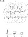
- an electrical distribution network 1 is shown schematically, which is connected at the connection point 2 to an upstream network (not shown) and distributes the electrical line coming from there via a branched line network 3.
- a multiplicity of devices 4.1 to 4.11 are connected to the distribution network 1, each of which, in the active state, emits a radio signal that can be identified by one of the receiving units 9.1 to 9.3 explained later and can be clearly assigned to a device 4.1-4.11.
- the range of the respective radio signal is indicated by the dashed circles around the respective devices 4.1-4.11.
- the device 4.2 has an uninterruptible power supply 6 so that it can still be operated even if the distribution network 1 fails.
- the device 4.6 is connected to the distribution network 1 via a timer 7 and is only active from 9:00 a.m. to 5:00 p.m.
- a further device 8 which, although it also sends out identifiable and assignable radio signals, is operated completely independently of the distribution network 1 with a battery.
- FIG. 1 In the area of distribution network 1, in Figure 1 three receiving units 9.1, 9.2 and 9.3 are also shown. These receiving units 9.1, 9.2 and 9.3 are cell phones or smartphones that are designed to receive the radio signals transmitted by the devices 4.1-4.11, 8 in the active state and also via a position determination module (not shown) to determine the position of the respective receiving units 9.1, 9.2, 9.3 have.
- the receiving units 9.1, 9.2 and 9.3 also have a communication module so that data relating to the position of the receiving unit 9.1, 9.2, 9.3 and the radio signals received by the receiving unit 9.1, 9.2, 9.3 are transmitted to a computer 11 via a cellular network indicated by a cellular tower 10 can be.
- the computer 11 also has access to a database 12.
- Position information on all devices 4.1-4.11, 8 is recorded in the database 12, the information both information on the geographical position in the form of geographical coordinates and information on the position in the network topology - i.e. on which line 3 in the supply network 1 the respective device 4.1-4.11, 8 is connected - includes. Furthermore, it is noted in the database 12 that the device 4.2 has an uninterruptible power supply 6, the device 4.6 is only switched on at certain times of the day and the device 8 is battery-operated.
- a receiving unit 9.1, 9.2, 9.3 transmits the information about the received radio signals regularly, when a sudden loss of one or more radio signals is detected, or at the express command of a user, on the basis of which the devices 4.1-4.11, 8 are identifiable and the individual radio signals can be clearly assigned to a single device 4.1-4.11, 8, via the cellular network 10 to the computer 11.
- the receiving units 9.1, 9.2, 9.3 also transmit the position determined by their respective position determination module the receiving unit 9.1, 9.2, 9.3.
- the position is determined on the basis of GPS signals, the position determination accuracy can be increased in a known manner by evaluating WLAN signals - which can be, for example, radio signals transmitted by devices 4.1-4.11, 8.
- the position of the receiving unit 9.1, 9.2, 9.3 is determined in geographical coordinates.
- the computer 11 can use the database 12 to determine which devices 4.1-4.11, 8 are basically located in the vicinity of the respective receiving unit 9.1, 9.2, 9.3. In other words, it can be determined from which devices 4.1-4.11, 8 a receiving unit 9.1, 9.2, 9.3 should basically receive radio signals in view of the respective range 5, provided that the devices 4.1-4.11, 8 are active.
- the devices 4.3, 4.4 and 4.7 for the receiving unit 9.1 the devices 4.1, 4.2, 4.5, 4.6 and 8 for the receiving unit 9.2 and the devices 4.6, 4.9 and 4.10 for the receiving unit 9.3.
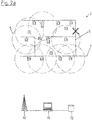
- Figure 2a is a first failure of the supply network 1 according to Figure 1 shown.
- the actual fault is marked as X and completely interrupts the power supply to the devices behind the fault, starting from connection point 2.
- Devices 4.1, 4.2, 4.3 and 4.4 are therefore affected by the malfunction.
- active and inactive devices 4.1-4.11, 8 can be determined for each receiving unit 9.1, 9.2, 9.3 .
- the receiving unit 9.1 it can thus be determined that the devices 4.3, 4.4, whose radio signals would basically have to be received, are obviously deactivated, while the device 4.7 is still sending radio signals, that is to say the device 4.7 is active. Already With this information it can be deduced from the network topology - possibly automated by the computer 11 - that the fault is presumably between the line branch 3.1 and the device 4.4.
- the results of the other receiving units 9.2 and 9.3 can confirm this assumption. Since the receiving unit 9.3 continues to receive the radio signals from the devices 4.9 and 4.10, it can be assumed that the line between the connection point 2 and the device 4.9 is free of interference. However, the fact that no radio signals can be received by the device 4.6 does not indicate a fault in its supply line, since this device 4.6 in the in Figure 2a The state shown is switched off by the timer 7 and has thus been systematically deactivated. Since corresponding information about the temporary deactivation of the device 4.6 is stored in the database 12, the computer 11 can identify the absence of the radio signals from the device 4.6 as a correct state that does not indicate a network fault.
- the receiving unit 9.2 can no longer receive any radio signals from the device 4.6 either, which, however, based on the information from the database 12, is not interpreted as a fault in the supply network 1. Since the receiving unit 9.2 still does not receive any signals from the device 4.1, but only from the devices 4.2, 4.5 and 8, this also indicates a fault in the line 3 which, starting from the line branch 3.1, leads to the device 4.1. Since it is known from the database 12 that the device 4.2 has an uninterruptible power supply, it is avoided that the radio signals of this device 4.2 are mistakenly viewed as an indication of a functioning energy supply of the device 4.2 by the supply network 1.
- Figure 2b is an alternative fault in the supply network 1 according to Figure 1 shown.
- the malfunction marked as X occurs in the line between devices 4.3 and 4.4.
- the receiving unit 9.1 receives the malfunction in accordance with Figure 2b but also the radio signals of the device 4.4.
- the computer 11 By evaluating the computer 11, as in connection with Figures 1 and 2 B can be determined immediately that the fault is probably in the line between device 4.3 and 4.4.
- the radio signals transmitted by the devices 4.1-4.11, 8 are WLAN signals, in particular WLAN beacons, which can be received and evaluated without, for example, a receiving unit 9.1, 9.2, 9.3 being connected to the corresponding WLAN would have to.
Landscapes
- Engineering & Computer Science (AREA)
- Power Engineering (AREA)
- Physics & Mathematics (AREA)
- General Physics & Mathematics (AREA)
- Computer Networks & Wireless Communication (AREA)
- Mobile Radio Communication Systems (AREA)
- Remote Monitoring And Control Of Power-Distribution Networks (AREA)
- Locating Faults (AREA)
- Monitoring And Testing Of Transmission In General (AREA)
- Emergency Protection Circuit Devices (AREA)
- Position Fixing By Use Of Radio Waves (AREA)
Claims (12)
- Procédé permettant de localiser des perturbations (X) dans un réseau de distribution d'électricité (1), doté d'une unité de réception (9.1, 9.2, 9.3) comprenant un module de détermination de position et d'une base de données (12) comprenant des informations de position concernant des appareils (4.1 à 4.11) connectés au réseau de distribution (1) qui émettent des signaux radio pouvant être identifiés par l'unité de réception (9.1, 9.2, 9.3) et associés à l'appareil respectif (4.14.11),
caractérisé en ce que les informations de position comprennent des indications concernant la position géographique, et l'unité de réception (9.1, 9.2, 9.3) est un terminal mobile, et le procédé comprend les étapes suivantes consistant à :a. trouver les appareils actifs (4.1 à 4.11) situés à proximité de l'unité de réception (9.1, 9.2, 9.3) à l'aide des signaux radio émis par ces appareils (4.14.11) qui peuvent être identifiés et associés à l'appareil respectif (4.1 à 4.11) ;b. déterminer la position de l'unité de réception (9.1, 9.2, 9.3) par le module de détermination de position ;c. trouver des appareils (4.1 à 4.11) situés à proximité de l'unité de réception (9.1, 9.2, 9.3) à partir de la base de données sur la base de la position trouvée de l'unité de réception (9.1, 9.2, 9.3) ;d. trouver les appareils désactivés (4.1 à 4.11) à proximité de l'unité de réception (9.1, 9.2, 9.3) par un recoupement entre les appareils actifs trouvés (4.14.11) et les appareils trouvés (4.1 à 4.11) situés à proximité de l'unité de réception (9.1, 9.2, 9.3) ; ete. localiser la perturbation dans le réseau de distribution par l'évaluation des informations de position des appareils activés et désactivés trouvés (4.1 à 4.11). - Procédé selon la revendication 1, caractérisé en ce que les informations de position comprennent des indications concernant la position dans la topologie de réseau.
- Procédé selon la revendication 1 ou 2, caractérisé en ce que la base de données (12) comprenant des informations de position comprend des informations concernant l'activation et la désactivation en fonction du temps d'au moins une partie des appareils (4.6) connectés au réseau de distribution (1) et/ou des informations indiquant si des appareils (4.2) connectés au réseau de distribution (1) disposent d'une alimentation électrique sans interruption (6).
- Procédé selon l'une quelconque des revendications précédentes, caractérisé en ce que la base de données (12) comprend des informations de position d'appareils (8) non connectés au réseau de distribution (1) qui émettent des signaux radio pouvant être identifiés par l'unité de réception (9.1, 9.2, 9.3) et associés à l'appareil respectif (8).
- Procédé selon l'une quelconque des revendications précédentes, caractérisé en ce que les appareils (4.1 à 4.11) connectés au réseau de distribution (1) comprennent des appareils appartenant à l'opérateur du réseau.
- Procédé selon l'une quelconque des revendications précédentes, caractérisé en ce que l'unité de réception (9.1, 9.2, 9.3) est un téléphone mobile ou une tablette.
- Procédé selon la revendication 6, caractérisé en ce que la modification du processus de chargement et/ou l'incidence de lumière sur une caméra du téléphone mobile sont prises en compte comme des informations supplémentaires concernant l'état du réseau de distribution (1) au niveau de l'unité de réception (9.1, 9.2, 9.3) lors de la localisation de la perturbation dans le réseau de distribution (1).
- Procédé selon l'une quelconque des revendications précédentes, caractérisé en ce que la base de données (12) est auto-adaptative et des informations concernant la connexion aux réseaux de distribution et/ou une alimentation électrique sans interruption (6) d'appareils individuels (4.1 à 4.11) sont mises à jour si nécessaire.
- Procédé selon l'une quelconque des revendications précédentes, caractérisé en ce que le module de détermination de position est réalisé pour déterminer la position de l'unité de réception (9.1, 9.2, 9.3) par des signaux de navigation par satellite, par une évaluation des signaux radio pouvant être identifiés par l'unité de réception (9.1, 9.2, 9.3) et associés à un appareil (4.1 à 4.11, 8) et/ou par la récupération d'une position enregistrée dans une mémoire.
- Procédé selon l'une quelconque des revendications précédentes, caractérisé en ce que les signaux radio pouvant être identifiés par l'unité de réception (9.1, 9.2, 9.3) et associés à un appareil (4.1 à 4.11, 8) sont des signaux WLAN, Bluetooth, Zigbee, Z-Wave et/ou EnOcean.
- Agencement permettant de localiser des perturbations (X) dans un réseau de distribution d'électricité (1) comprenant une unité de réception (9.1, 9.2, 9.3) dotée d'un module de détermination de position, une base de données (12) comprenant des informations de position concernant des appareils (4.1 à 4.11) connectés au réseau de distribution (1) qui émettent des signaux radio pouvant être identifiés par l'unité de réception (9.1, 9.2, 9.3) et associés à l'appareil respectif (4.1 à 4.11), et un ordinateur (11),
caractérisé en ce que les informations de position comprennent des indications concernant la position géographique, l'unité de réception (9.1, 9.2, 9.3) est un terminal mobile, et l'ordinateur (11) est réalisé pour trouver à l'aide de la position trouvée par le module de détermination de position de l'unité de réception (9.1, 9.2, 9.3) à partir de la base de données (12) les appareils situés à proximité de l'unité de réception (9.1, 9.2, 9.3) et pour vérifier à l'aide des signaux radio reçus par l'unité de réception (9.1, 9.2, 9.3) ceux des appareils ainsi trouvés qui sont activés et ceux des appareils ainsi trouvés qui sont désactivés afin de localiser une perturbation dans le réseau de distribution (1) par l'évaluation des informations de position des appareils activés et désactivés trouvés. - Agencement selon la revendication 11, caractérisé en ce que l'agencement est réalisé pour exécuter un procédé selon l'une quelconque des revendications 1 à 10.
Priority Applications (1)
| Application Number | Priority Date | Filing Date | Title |
|---|---|---|---|
| PL17729496T PL3475709T3 (pl) | 2016-06-27 | 2017-06-15 | Sposób i układ do lokalizacji zakłóceń w elektrycznych sieciach rozdzielczych |
Applications Claiming Priority (2)
| Application Number | Priority Date | Filing Date | Title |
|---|---|---|---|
| EP16176487.3A EP3264113A1 (fr) | 2016-06-27 | 2016-06-27 | Procédé et dispositif de localisation de perturbations dans des réseaux de distribution d'electricite |
| PCT/EP2017/064655 WO2018001745A1 (fr) | 2016-06-27 | 2017-06-15 | Procédé et système permettant de localiser des parasites dans des réseaux de distribution électriques |
Publications (2)
| Publication Number | Publication Date |
|---|---|
| EP3475709A1 EP3475709A1 (fr) | 2019-05-01 |
| EP3475709B1 true EP3475709B1 (fr) | 2021-08-04 |
Family
ID=56289330
Family Applications (2)
| Application Number | Title | Priority Date | Filing Date |
|---|---|---|---|
| EP16176487.3A Withdrawn EP3264113A1 (fr) | 2016-06-27 | 2016-06-27 | Procédé et dispositif de localisation de perturbations dans des réseaux de distribution d'electricite |
| EP17729496.4A Active EP3475709B1 (fr) | 2016-06-27 | 2017-06-15 | Procédé et dispositif de localisation de perturbations dans des réseaux de distribution d'electricite |
Family Applications Before (1)
| Application Number | Title | Priority Date | Filing Date |
|---|---|---|---|
| EP16176487.3A Withdrawn EP3264113A1 (fr) | 2016-06-27 | 2016-06-27 | Procédé et dispositif de localisation de perturbations dans des réseaux de distribution d'electricite |
Country Status (12)
| Country | Link |
|---|---|
| US (1) | US20190235012A1 (fr) |
| EP (2) | EP3264113A1 (fr) |
| JP (1) | JP2019528429A (fr) |
| KR (1) | KR20190057046A (fr) |
| CN (1) | CN109642922A (fr) |
| AU (1) | AU2017288693A1 (fr) |
| BR (1) | BR112018076750A2 (fr) |
| CA (1) | CA3027782A1 (fr) |
| HU (1) | HUE057227T2 (fr) |
| PL (1) | PL3475709T3 (fr) |
| RU (1) | RU2019101891A (fr) |
| WO (1) | WO2018001745A1 (fr) |
Families Citing this family (2)
| Publication number | Priority date | Publication date | Assignee | Title |
|---|---|---|---|---|
| KR102621741B1 (ko) | 2019-05-15 | 2024-01-04 | 주식회사 엘지에너지솔루션 | 전고체 전지용 전극 및 이를 포함하는 전극 조립체의 제조 방법 |
| CN110687332A (zh) * | 2019-11-11 | 2020-01-14 | 浙江巨磁智能技术有限公司 | 开关侧主动式电表和断路器自动配对方法 |
Family Cites Families (12)
| Publication number | Priority date | Publication date | Assignee | Title |
|---|---|---|---|---|
| JP2906938B2 (ja) * | 1993-09-07 | 1999-06-21 | 日新電機株式会社 | 道路設備機器監視システム |
| JPH1141796A (ja) * | 1997-07-18 | 1999-02-12 | Nissin Electric Co Ltd | 連接型設備機器配電線の地絡区間標定システム |
| JP4649826B2 (ja) * | 2003-09-24 | 2011-03-16 | パナソニック電工株式会社 | 道路灯監視装置および監視方法 |
| JP2005100764A (ja) * | 2003-09-24 | 2005-04-14 | Matsushita Electric Works Ltd | 道路灯監視装置および監視方法 |
| US20100017214A1 (en) * | 2008-07-15 | 2010-01-21 | Ronald Ambrosio | Extended services oriented architecture for distributed analytics |
| US8040812B1 (en) * | 2009-05-05 | 2011-10-18 | Sprint Communications Company L.P. | Network outage assessment |
| US8810251B2 (en) * | 2011-08-31 | 2014-08-19 | General Electric Company | Systems, methods, and apparatus for locating faults on an electrical distribution network |
| US20140278162A1 (en) | 2013-03-15 | 2014-09-18 | Echelon Corporation | Detecting and locating power outages via low voltage grid mapping |
| US9841456B2 (en) * | 2014-07-16 | 2017-12-12 | International Business Machines Corporation | Electric outage detection and localization |
| EP3183943A1 (fr) * | 2014-08-19 | 2017-06-28 | Philips Lighting Holding B.V. | Système de détection de défauts |
| US10064257B2 (en) * | 2014-10-28 | 2018-08-28 | Philips Lighting Holding B.V. | Method and arrangement for monitoring of lighting systems, and a monitored lighting installation |
| CN107210932B (zh) * | 2015-01-14 | 2021-04-06 | 飞利浦灯具控股公司 | 用于在网络系统中启用故障恢复的网络节点与方法以及计算机可读介质 |
-
2016
- 2016-06-27 EP EP16176487.3A patent/EP3264113A1/fr not_active Withdrawn
-
2017
- 2017-06-15 RU RU2019101891A patent/RU2019101891A/ru not_active Application Discontinuation
- 2017-06-15 CA CA3027782A patent/CA3027782A1/fr not_active Abandoned
- 2017-06-15 BR BR112018076750-6A patent/BR112018076750A2/pt not_active Application Discontinuation
- 2017-06-15 EP EP17729496.4A patent/EP3475709B1/fr active Active
- 2017-06-15 HU HUE17729496A patent/HUE057227T2/hu unknown
- 2017-06-15 KR KR1020197002706A patent/KR20190057046A/ko not_active Ceased
- 2017-06-15 CN CN201780039886.2A patent/CN109642922A/zh active Pending
- 2017-06-15 JP JP2018566911A patent/JP2019528429A/ja active Pending
- 2017-06-15 PL PL17729496T patent/PL3475709T3/pl unknown
- 2017-06-15 WO PCT/EP2017/064655 patent/WO2018001745A1/fr not_active Ceased
- 2017-06-15 US US16/312,073 patent/US20190235012A1/en not_active Abandoned
- 2017-06-15 AU AU2017288693A patent/AU2017288693A1/en not_active Abandoned
Non-Patent Citations (1)
| Title |
|---|
| None * |
Also Published As
| Publication number | Publication date |
|---|---|
| CN109642922A (zh) | 2019-04-16 |
| KR20190057046A (ko) | 2019-05-27 |
| WO2018001745A1 (fr) | 2018-01-04 |
| EP3264113A1 (fr) | 2018-01-03 |
| CA3027782A1 (fr) | 2018-01-04 |
| US20190235012A1 (en) | 2019-08-01 |
| RU2019101891A (ru) | 2020-07-24 |
| HUE057227T2 (hu) | 2022-04-28 |
| BR112018076750A2 (pt) | 2019-03-26 |
| JP2019528429A (ja) | 2019-10-10 |
| EP3475709A1 (fr) | 2019-05-01 |
| PL3475709T3 (pl) | 2021-12-27 |
| AU2017288693A1 (en) | 2019-01-17 |
Similar Documents
| Publication | Publication Date | Title |
|---|---|---|
| EP3336995B1 (fr) | Procédé, dispositif de commande et système de détermination de valeurs d'état pour décrire des états de fonctionnement dans un sous-réseau d'un réseau de distribution d'énergie | |
| EP2992391A1 (fr) | Module d'interface électrique | |
| WO2013174415A1 (fr) | Procédé et dispositif d'association de plusieurs conducteurs de phase dans un réseau de distribution d'énergie polyphasé | |
| EP3475709B1 (fr) | Procédé et dispositif de localisation de perturbations dans des réseaux de distribution d'electricite | |
| EP2805185B1 (fr) | Procédé pour faire fonctionner un appareil de terrain, appareil de terrain, et serveur pour un réseau d'automatisation de grande surface | |
| EP4403932A1 (fr) | Procédé et dispositif de détection précoce d'erreur de câble | |
| EP3324506B1 (fr) | Procédé de réalisation d'une base de données destinée à représenter la topologie d'un réseau de distribution électrique et utilisation de ladite base de données | |
| DE102012220846B3 (de) | Verfahren zur Topologieerkennung in einem Niederspannungsnetz | |
| EP2910903A1 (fr) | Procédé de détection du vol de courant dans un réseau basse tension | |
| EP3126991A1 (fr) | Module d'interface électrique | |
| EP2437228B1 (fr) | Alarme, installation d'alarme et procédé de reconnaissance d'erreurs de lignes de transmission | |
| EP3408970A1 (fr) | Procédé de détection et de détermination de la probabilité de défaut d'un réseau radio et ordinateur central | |
| WO2020193062A1 (fr) | Système de traitement de données et procédé de traitement de données | |
| AT518598A1 (de) | Überwachen der Inbetriebnahme und der Plausibilität von Daten eines Leistungsmesssensors in einem Verteilernetz | |
| DE102013113978A1 (de) | Modularer RFID-Reader | |
| CN118117738B (zh) | 线变关系更改系统及方法 | |
| DE102010034961B4 (de) | Verfahren zum Betrieb einer Vorrichtung zum Erfassen von Verbrauchswerten in einem Gebäude anfallender Verbrauchsmengen | |
| DE102023101473A1 (de) | Verfahren und Vorrichtung zur Kabelfehlerfrüherkennung | |
| Nguyen et al. | A novel strategy for failure-tolerant communication in smart grids | |
| EP3216101B1 (fr) | Procédé d'association mutuelle de noeuds d'un réseau basse tension | |
| DE102014222598A1 (de) | Trennen von fehlerhaften Netzabschnitten eines Niederspannungsnetzes von weiteren Netzabschnitten | |
| WO2025011847A1 (fr) | Module matériel, serveur en nuage et système pour un réseau d'alimentation électrique | |
| DE102005024483A1 (de) | Verfahren und Vorrichtung zum Ermitteln des Ortes eines Kurzschlusses in einer Leitung eines Energieversorgungsnetzes | |
| DE102022131076A1 (de) | Technik zur Gebäudesteuerung | |
| DE112021006642T5 (de) | Zustandsüberwachungseinrichtung, drahtlose bodeneinrichtung, integrierte drahtlose einrichtung, ausfallrisiko-bestimmungsverfahren, steuerschaltung und speichermedium |
Legal Events
| Date | Code | Title | Description |
|---|---|---|---|
| STAA | Information on the status of an ep patent application or granted ep patent |
Free format text: STATUS: UNKNOWN |
|
| STAA | Information on the status of an ep patent application or granted ep patent |
Free format text: STATUS: THE INTERNATIONAL PUBLICATION HAS BEEN MADE |
|
| PUAI | Public reference made under article 153(3) epc to a published international application that has entered the european phase |
Free format text: ORIGINAL CODE: 0009012 |
|
| STAA | Information on the status of an ep patent application or granted ep patent |
Free format text: STATUS: REQUEST FOR EXAMINATION WAS MADE |
|
| 17P | Request for examination filed |
Effective date: 20190122 |
|
| AK | Designated contracting states |
Kind code of ref document: A1 Designated state(s): AL AT BE BG CH CY CZ DE DK EE ES FI FR GB GR HR HU IE IS IT LI LT LU LV MC MK MT NL NO PL PT RO RS SE SI SK SM TR |
|
| AX | Request for extension of the european patent |
Extension state: BA ME |
|
| DAV | Request for validation of the european patent (deleted) | ||
| DAX | Request for extension of the european patent (deleted) | ||
| STAA | Information on the status of an ep patent application or granted ep patent |
Free format text: STATUS: EXAMINATION IS IN PROGRESS |
|
| 17Q | First examination report despatched |
Effective date: 20200715 |
|
| REG | Reference to a national code |
Ref country code: DE Ref legal event code: R079 Ref document number: 502017011101 Country of ref document: DE Free format text: PREVIOUS MAIN CLASS: G01R0031080000 Ipc: H02J0003000000 |
|
| GRAP | Despatch of communication of intention to grant a patent |
Free format text: ORIGINAL CODE: EPIDOSNIGR1 |
|
| STAA | Information on the status of an ep patent application or granted ep patent |
Free format text: STATUS: GRANT OF PATENT IS INTENDED |
|
| RIC1 | Information provided on ipc code assigned before grant |
Ipc: H02J 3/00 20060101AFI20210217BHEP Ipc: G01R 31/08 20200101ALI20210217BHEP Ipc: H02J 13/00 20060101ALI20210217BHEP |
|
| INTG | Intention to grant announced |
Effective date: 20210311 |
|
| GRAS | Grant fee paid |
Free format text: ORIGINAL CODE: EPIDOSNIGR3 |
|
| GRAA | (expected) grant |
Free format text: ORIGINAL CODE: 0009210 |
|
| STAA | Information on the status of an ep patent application or granted ep patent |
Free format text: STATUS: THE PATENT HAS BEEN GRANTED |
|
| AK | Designated contracting states |
Kind code of ref document: B1 Designated state(s): AL AT BE BG CH CY CZ DE DK EE ES FI FR GB GR HR HU IE IS IT LI LT LU LV MC MK MT NL NO PL PT RO RS SE SI SK SM TR |
|
| REG | Reference to a national code |
Ref country code: GB Ref legal event code: FG4D Free format text: NOT ENGLISH |
|
| REG | Reference to a national code |
Ref country code: AT Ref legal event code: REF Ref document number: 1417987 Country of ref document: AT Kind code of ref document: T Effective date: 20210815 |
|
| REG | Reference to a national code |
Ref country code: CH Ref legal event code: EP |
|
| REG | Reference to a national code |
Ref country code: DE Ref legal event code: R096 Ref document number: 502017011101 Country of ref document: DE |
|
| REG | Reference to a national code |
Ref country code: IE Ref legal event code: FG4D Free format text: LANGUAGE OF EP DOCUMENT: GERMAN |
|
| REG | Reference to a national code |
Ref country code: SE Ref legal event code: TRGR |
|
| REG | Reference to a national code |
Ref country code: SK Ref legal event code: T3 Ref document number: E 38230 Country of ref document: SK |
|
| REG | Reference to a national code |
Ref country code: LT Ref legal event code: MG9D |
|
| REG | Reference to a national code |
Ref country code: NL Ref legal event code: MP Effective date: 20210804 |
|
| PG25 | Lapsed in a contracting state [announced via postgrant information from national office to epo] |
Ref country code: RS Free format text: LAPSE BECAUSE OF FAILURE TO SUBMIT A TRANSLATION OF THE DESCRIPTION OR TO PAY THE FEE WITHIN THE PRESCRIBED TIME-LIMIT Effective date: 20210804 Ref country code: HR Free format text: LAPSE BECAUSE OF FAILURE TO SUBMIT A TRANSLATION OF THE DESCRIPTION OR TO PAY THE FEE WITHIN THE PRESCRIBED TIME-LIMIT Effective date: 20210804 Ref country code: PT Free format text: LAPSE BECAUSE OF FAILURE TO SUBMIT A TRANSLATION OF THE DESCRIPTION OR TO PAY THE FEE WITHIN THE PRESCRIBED TIME-LIMIT Effective date: 20211206 Ref country code: NO Free format text: LAPSE BECAUSE OF FAILURE TO SUBMIT A TRANSLATION OF THE DESCRIPTION OR TO PAY THE FEE WITHIN THE PRESCRIBED TIME-LIMIT Effective date: 20211104 Ref country code: FI Free format text: LAPSE BECAUSE OF FAILURE TO SUBMIT A TRANSLATION OF THE DESCRIPTION OR TO PAY THE FEE WITHIN THE PRESCRIBED TIME-LIMIT Effective date: 20210804 Ref country code: ES Free format text: LAPSE BECAUSE OF FAILURE TO SUBMIT A TRANSLATION OF THE DESCRIPTION OR TO PAY THE FEE WITHIN THE PRESCRIBED TIME-LIMIT Effective date: 20210804 Ref country code: BG Free format text: LAPSE BECAUSE OF FAILURE TO SUBMIT A TRANSLATION OF THE DESCRIPTION OR TO PAY THE FEE WITHIN THE PRESCRIBED TIME-LIMIT Effective date: 20211104 Ref country code: LT Free format text: LAPSE BECAUSE OF FAILURE TO SUBMIT A TRANSLATION OF THE DESCRIPTION OR TO PAY THE FEE WITHIN THE PRESCRIBED TIME-LIMIT Effective date: 20210804 |
|
| PG25 | Lapsed in a contracting state [announced via postgrant information from national office to epo] |
Ref country code: LV Free format text: LAPSE BECAUSE OF FAILURE TO SUBMIT A TRANSLATION OF THE DESCRIPTION OR TO PAY THE FEE WITHIN THE PRESCRIBED TIME-LIMIT Effective date: 20210804 Ref country code: GR Free format text: LAPSE BECAUSE OF FAILURE TO SUBMIT A TRANSLATION OF THE DESCRIPTION OR TO PAY THE FEE WITHIN THE PRESCRIBED TIME-LIMIT Effective date: 20211105 |
|
| PG25 | Lapsed in a contracting state [announced via postgrant information from national office to epo] |
Ref country code: NL Free format text: LAPSE BECAUSE OF FAILURE TO SUBMIT A TRANSLATION OF THE DESCRIPTION OR TO PAY THE FEE WITHIN THE PRESCRIBED TIME-LIMIT Effective date: 20210804 |
|
| REG | Reference to a national code |
Ref country code: HU Ref legal event code: AG4A Ref document number: E057227 Country of ref document: HU |
|
| PG25 | Lapsed in a contracting state [announced via postgrant information from national office to epo] |
Ref country code: DK Free format text: LAPSE BECAUSE OF FAILURE TO SUBMIT A TRANSLATION OF THE DESCRIPTION OR TO PAY THE FEE WITHIN THE PRESCRIBED TIME-LIMIT Effective date: 20210804 |
|
| REG | Reference to a national code |
Ref country code: DE Ref legal event code: R097 Ref document number: 502017011101 Country of ref document: DE |
|
| PG25 | Lapsed in a contracting state [announced via postgrant information from national office to epo] |
Ref country code: SM Free format text: LAPSE BECAUSE OF FAILURE TO SUBMIT A TRANSLATION OF THE DESCRIPTION OR TO PAY THE FEE WITHIN THE PRESCRIBED TIME-LIMIT Effective date: 20210804 Ref country code: RO Free format text: LAPSE BECAUSE OF FAILURE TO SUBMIT A TRANSLATION OF THE DESCRIPTION OR TO PAY THE FEE WITHIN THE PRESCRIBED TIME-LIMIT Effective date: 20210804 Ref country code: EE Free format text: LAPSE BECAUSE OF FAILURE TO SUBMIT A TRANSLATION OF THE DESCRIPTION OR TO PAY THE FEE WITHIN THE PRESCRIBED TIME-LIMIT Effective date: 20210804 Ref country code: AL Free format text: LAPSE BECAUSE OF FAILURE TO SUBMIT A TRANSLATION OF THE DESCRIPTION OR TO PAY THE FEE WITHIN THE PRESCRIBED TIME-LIMIT Effective date: 20210804 |
|
| PLBE | No opposition filed within time limit |
Free format text: ORIGINAL CODE: 0009261 |
|
| STAA | Information on the status of an ep patent application or granted ep patent |
Free format text: STATUS: NO OPPOSITION FILED WITHIN TIME LIMIT |
|
| 26N | No opposition filed |
Effective date: 20220506 |
|
| PG25 | Lapsed in a contracting state [announced via postgrant information from national office to epo] |
Ref country code: IT Free format text: LAPSE BECAUSE OF FAILURE TO SUBMIT A TRANSLATION OF THE DESCRIPTION OR TO PAY THE FEE WITHIN THE PRESCRIBED TIME-LIMIT Effective date: 20210804 |
|
| PG25 | Lapsed in a contracting state [announced via postgrant information from national office to epo] |
Ref country code: SI Free format text: LAPSE BECAUSE OF FAILURE TO SUBMIT A TRANSLATION OF THE DESCRIPTION OR TO PAY THE FEE WITHIN THE PRESCRIBED TIME-LIMIT Effective date: 20210804 |
|
| PG25 | Lapsed in a contracting state [announced via postgrant information from national office to epo] |
Ref country code: MC Free format text: LAPSE BECAUSE OF FAILURE TO SUBMIT A TRANSLATION OF THE DESCRIPTION OR TO PAY THE FEE WITHIN THE PRESCRIBED TIME-LIMIT Effective date: 20210804 |
|
| REG | Reference to a national code |
Ref country code: CH Ref legal event code: PL |
|
| REG | Reference to a national code |
Ref country code: BE Ref legal event code: MM Effective date: 20220630 |
|
| PG25 | Lapsed in a contracting state [announced via postgrant information from national office to epo] |
Ref country code: LU Free format text: LAPSE BECAUSE OF NON-PAYMENT OF DUE FEES Effective date: 20220615 Ref country code: LI Free format text: LAPSE BECAUSE OF NON-PAYMENT OF DUE FEES Effective date: 20220630 Ref country code: IE Free format text: LAPSE BECAUSE OF NON-PAYMENT OF DUE FEES Effective date: 20220615 Ref country code: CH Free format text: LAPSE BECAUSE OF NON-PAYMENT OF DUE FEES Effective date: 20220630 |
|
| PG25 | Lapsed in a contracting state [announced via postgrant information from national office to epo] |
Ref country code: BE Free format text: LAPSE BECAUSE OF NON-PAYMENT OF DUE FEES Effective date: 20220630 |
|
| REG | Reference to a national code |
Ref country code: AT Ref legal event code: MM01 Ref document number: 1417987 Country of ref document: AT Kind code of ref document: T Effective date: 20220615 |
|
| PG25 | Lapsed in a contracting state [announced via postgrant information from national office to epo] |
Ref country code: AT Free format text: LAPSE BECAUSE OF NON-PAYMENT OF DUE FEES Effective date: 20220615 |
|
| PG25 | Lapsed in a contracting state [announced via postgrant information from national office to epo] |
Ref country code: MK Free format text: LAPSE BECAUSE OF FAILURE TO SUBMIT A TRANSLATION OF THE DESCRIPTION OR TO PAY THE FEE WITHIN THE PRESCRIBED TIME-LIMIT Effective date: 20210804 Ref country code: CY Free format text: LAPSE BECAUSE OF FAILURE TO SUBMIT A TRANSLATION OF THE DESCRIPTION OR TO PAY THE FEE WITHIN THE PRESCRIBED TIME-LIMIT Effective date: 20210804 |
|
| PG25 | Lapsed in a contracting state [announced via postgrant information from national office to epo] |
Ref country code: TR Free format text: LAPSE BECAUSE OF FAILURE TO SUBMIT A TRANSLATION OF THE DESCRIPTION OR TO PAY THE FEE WITHIN THE PRESCRIBED TIME-LIMIT Effective date: 20210804 |
|
| PG25 | Lapsed in a contracting state [announced via postgrant information from national office to epo] |
Ref country code: MT Free format text: LAPSE BECAUSE OF FAILURE TO SUBMIT A TRANSLATION OF THE DESCRIPTION OR TO PAY THE FEE WITHIN THE PRESCRIBED TIME-LIMIT Effective date: 20210804 |
|
| PGFP | Annual fee paid to national office [announced via postgrant information from national office to epo] |
Ref country code: PL Payment date: 20250604 Year of fee payment: 9 Ref country code: DE Payment date: 20250618 Year of fee payment: 9 |
|
| PGFP | Annual fee paid to national office [announced via postgrant information from national office to epo] |
Ref country code: GB Payment date: 20250620 Year of fee payment: 9 |
|
| PGFP | Annual fee paid to national office [announced via postgrant information from national office to epo] |
Ref country code: HU Payment date: 20250613 Year of fee payment: 9 Ref country code: FR Payment date: 20250618 Year of fee payment: 9 |
|
| PGFP | Annual fee paid to national office [announced via postgrant information from national office to epo] |
Ref country code: SK Payment date: 20250611 Year of fee payment: 9 |
|
| PGFP | Annual fee paid to national office [announced via postgrant information from national office to epo] |
Ref country code: CZ Payment date: 20250530 Year of fee payment: 9 |
|
| PGFP | Annual fee paid to national office [announced via postgrant information from national office to epo] |
Ref country code: SE Payment date: 20250618 Year of fee payment: 9 |