EP3475931B1 - Verfahren zum betrieb einer alarmanlage mit einer entfernten vorrichtung - Google Patents
Verfahren zum betrieb einer alarmanlage mit einer entfernten vorrichtung Download PDFInfo
- Publication number
- EP3475931B1 EP3475931B1 EP17732144.5A EP17732144A EP3475931B1 EP 3475931 B1 EP3475931 B1 EP 3475931B1 EP 17732144 A EP17732144 A EP 17732144A EP 3475931 B1 EP3475931 B1 EP 3475931B1
- Authority
- EP
- European Patent Office
- Prior art keywords
- alert
- operating mode
- alarm
- control centre
- operating
- Prior art date
- Legal status (The legal status is an assumption and is not a legal conclusion. Google has not performed a legal analysis and makes no representation as to the accuracy of the status listed.)
- Not-in-force
Links
Images


Classifications
-
- G—PHYSICS
- G08—SIGNALLING
- G08B—SIGNALLING SYSTEMS, e.g. PERSONAL CALLING SYSTEMS; ORDER TELEGRAPHS; ALARM SYSTEMS
- G08B25/00—Alarm systems in which the location of the alarm condition is signalled to a central station, e.g. fire or police telegraphic systems
- G08B25/008—Alarm setting and unsetting, i.e. arming or disarming of the security system
-
- G—PHYSICS
- G08—SIGNALLING
- G08B—SIGNALLING SYSTEMS, e.g. PERSONAL CALLING SYSTEMS; ORDER TELEGRAPHS; ALARM SYSTEMS
- G08B25/00—Alarm systems in which the location of the alarm condition is signalled to a central station, e.g. fire or police telegraphic systems
- G08B25/14—Central alarm receiver or annunciator arrangements
Definitions
- the present invention relates to the field of alarm systems, in particular domestic alarm systems.
- the document US5109222 discloses a security system comprising motion detectors connected to a central unit, and the display of the status of the system on the screen of a remote control.
- the invention relates to a home alarm system comprising a control unit provided with an alarm function, the alarm function having a plurality of selectable operating modes, at least one main selection means, each selection means. main for selecting an operating mode from among the plurality of selectable operating modes, at least one detection means, each detection means being able to transmit a detection signal to the control unit in response to a request from said detection means , at least one main alert means, each main alert means being able to emit an alert signal in response to an alarm activation signal from the control unit, the alarm system being characterized in that it comprises a remote device, the remote device comprising a secondary selection means, the secondary selection means making it possible to select a prem ier operating mode called "night" of the alarm function, a secondary alert means, the secondary alert means being able to emit an alert signal in response to an activation signal from the control unit control unit, and, the control unit refusing the selection of the first operating mode when an operating mode included in a first predefined list of operating modes is previously selected, and, when the first operating mode
- the secondary alert means when an intrusion is detected, the secondary alert means, more discreet and placed close to a user, is activated instead of the main alert means.
- control unit is also suitable for sending, after a predetermined time delay, a second alarm activation signal to the main alert means following the sending of the alarm. first activation signal by means of secondary alert.
- the main alert means is automatically activated after a certain time.
- the invention also relates to a method of operating, according to a first operating mode, an alarm function of a control unit of a domestic alarm system, the alarm function having a plurality of modes of operation. selectable operations, the home alarm system comprising a main alert means adapted to emit an alert signal in response to an alarm activation signal from the control unit, the method being executed by the control unit control and comprising the steps of receiving a message comprising a selection command of the first operating mode, the message from a remote device, validating the selection of the first operating mode, receiving at least one detection signal from a detection means and send a first alarm activation signal to a secondary alert means included in the remote device.
- the method comprises the subsequent step of sending a second alarm activation signal to the main alert means when a message comprising a command to activate the alarm means.
- main alert is received from the remote device.
- the method comprises the subsequent step of sending a second alarm activation signal to the main alert means when a predetermined time delay expires following the sending of the first activation signal.
- the present invention also relates to a computer program, comprising instructions for implementing, by a processor, the method of operating an alarm system comprising a remote device according to the invention, when said computer program is executed by said processor.
- the present invention also relates to storage means storing said computer program.
- the remote device 200 can be connected to the control unit 100 via a communication technology identical to that which makes it possible to connect the other elements to the control unit 100.
- the remote device 200 can also be connected to the control unit 100 via a different technology, which may require modifying the control unit 100 (adding a communication module for example).
- the remote device 200 is intended to be installed for example in a bedroom, ideally within easy reach of a bed.
- the remote device 200 can integrate other functions, particularly if the alarm system is included in a home automation system.
- the remote device 200 may include a switch making it possible to control, for example, the lighting of the room in which it is placed.
- the secondary selection means may comprise one or more keys.
- the remote device 200 comprises for example a first key allowing the selection of the first operating mode called “night” and a second key making it possible to cancel said selection.
- the remote device 200 can include a key to activate the first operating mode called “night” and a second key to deactivate it.
- the remote device 200 can include other keys.
- One of the keys can make it possible to control the immediate activation of the alert means (s) of the alarm system in a so-called “panic”, “distress” or “SOS” operating mode.
- the secondary alert means may include an audible or visual warning device, for example a beeper (or " buzzer " in English) or a flash.
- the objective of the local alert means is to be able to alert only the occupants of the room in which it is placed, it is not useful for the secondary alert means to be a powerful siren.
- the secondary alert means is activated in response to an alert activation signal sent by the control unit 100.
- the Fig. 3 schematically illustrates a hardware architecture of a remote device 200 used in an alarm system according to one embodiment of the invention.
- the remote device 200 comprises, connected by a communication bus: a processor or CPU ( Central Processing Unit ) 301; a random access memory RAM ( Random Access Memory ) 302; a ROM ( Read Only Memory ) 303; a storage unit or a storage medium drive, such as an SD (Secure Digital) card reader or an HDD (Hard Disk Drive ) 304; a NET communication interface 205; a secondary selection means 306 and a secondary alert means 307.
- the NET communication interface 305 makes it possible to connect the remote device 200 to the alarm system, that is to say to the control unit 100.
- the communication interface can be of the WiFi, Ethernet or any other communication technology type.
- the secondary selection means may include one or more keys, a touch screen, a numeric keypad or any other technology allowing a user of the alarm system to enter a selection.
- the secondary alert means may be a beeper, a flash or any other element making it possible to attract the attention of a user, particularly when the latter is asleep.
- Processor 301 is capable of executing instructions loaded into RAM 302 from ROM 303, STCK storage unit 404, or a communications network through the NET 305 communications interface. When the remote device 200 is powered on, processor 301 is able to read instructions from RAM 302 and execute them.
- the Fig. 4 schematically illustrates a hardware architecture of a control unit 100 used in an alarm system according to one embodiment of the invention.
- the control unit 100 comprises, connected by a communication bus: a processor or CPU ( Central Processing Unit ) 401; a memory long live RAM (Random Access Memory) 402; a ROM (Read Only Memory) 403; a storage unit or a storage medium drive, such as a SD (Secure Digital) card reader or an HDD (Hard Disk Drive) 404 and at least one NET 405 communication interface.
- the communication interface NET 405 is used to connect the various elements of the alarm system to the control unit 100.
- the NET 405 communication interface can be of WiFi, Ethernet or any other communication technology.
- the processor 401 is capable of executing instructions loaded into the RAM 402 from the ROM 403, from the STCK storage unit 404 or from a communication network via the NET 405 communication interface.
- control 100 is powered on, processor 401 is able to read instructions from RAM and execute them.
- These instructions form a computer program allowing the implementation or execution, by the processor 401, of all or part of the methods and steps described in this document.
- all or part of the methods and steps described in this document can be implemented in software form by executing a set of instructions by a programmable machine, such as a DSP (Digital Signal Processor) or a microcontroller.
- All or part of the modules, processes and steps described below can also be implemented in hardware form by a machine or a dedicated component, such as an FPGA ( Field-Programmable Gate Array ) or an ASIC ( Application-Specific Integrated) Tour in English).
- the Fig. 5 schematically illustrates an operating method, according to a so-called “night” operating mode, of an alarm function of a control unit 100 of a domestic alarm system according to one embodiment of the invention.
- the control unit 100 is provided with an alarm function, the alarm function having a plurality of selectable operating modes.
- alarm function is meant that the control unit 100 can manage an alarm system.
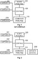
- An architecture of an alarm system that can be managed by the control unit 100 is illustrated in Fig. 2 .
- Said alarm system can therefore, following the detection of an intrusion, by requesting a detection means 101, 102 or 10N, trigger an activation of a main alert means such as a siren.
- An alarm system can operate in several modes of operation. One of these modes is the disabled or “OFF” mode in which the alarm system is inactive. In this state, the alarm system, that is to say the control unit 100, will not activate the main alert means, even in the event of an intrusion being detected.
- One of the modes is active or “ON” mode.
- an alert is emitted by the main alert means (emission of a high power sound signal for example).
- Another possible operating mode is that of “panic” or “SOS” mode. In this mode, following receipt of a selection of this mode by a user, the main alert means is immediately activated by the control unit 100 without taking into account the states of the detection means.
- Other modes are possible, particularly modes making it possible to partially activate the alarm system, only certain detection means being active for example. Thus, depending on the operating mode selected, only certain areas can be protected.
- a step 500 the alarm system, that is to say the control unit 100, is in an “N” operating mode.
- control unit 100 receives a message comprising a command for selecting a so-called “night” operating mode, the message coming from the remote device 200.
- the control unit 100 validates the selection of the “night” operating mode. In other words, the control unit 100 checks that the “night” operating mode can indeed be activated. Indeed, it may be judicious not to authorize the selection of the “night” operating mode until the control unit 100 is in a deactivated (or “OFF”) operating mode. In other words, it is judicious to refuse the activation of the so-called “night” operating mode if the control unit 100 is in an operating mode other than deactivated (“OFF”). In fact, it is often necessary to enter a PIN code to deactivate an operating mode of an alarm system. Without the verification step 510, it would then be possible to deactivate another operating mode easily by using the remote device 200.
- control unit 100 refuses, that is to say ignores, the command for selecting the first one. operating mode when an operating mode included in a first list is previously selected.
- the first list preferably includes any operating mode that must be activated by entering a PIN code.
- all the operating modes are included in the first list, except the so-called “OFF” operating mode, corresponding to the deactivation of the alarm system.
- the first mode operating mode can only be selected when the control unit 100 is in a disabled mode. In all other operating modes, the command to select the first operating mode is ignored.
- the operating unit If the operating unit is in a deactivated mode (or any other predefined operating mode for which it is authorized to switch to "night" operating mode, that is to say an operating mode not included in the first list ), then the operating unit goes to step 515. Otherwise, the selection message is ignored. According to one embodiment of the invention, rather than being ignored, the selection message can be considered as an intrusion detection signal.
- the operating mode of the control unit 100 is activated.
- all the detection means 101, 102 to 10N are activated.
- only certain detection means are activated (definition of a restricted surveillance zone).
- activated is meant that the “activated” detection means is capable of detecting a request and then sending a detection signal to the control unit 100.
- the activation or the deactivation of a detection means is managed at the level of the control unit 100, which can then ignore certain detection signals originating from detection means considered to be deactivated.
- the control unit 100 is in monitoring mode, waiting for a possible detection signal from a detection means.
- a step 520 the control unit 100 is therefore waiting for a possible detection signal. If a detection signal is received by the control unit, the control unit 100 goes to step 525. Otherwise, the control unit 100 remains in the “night” operating mode until a possible reception is received. command to deactivate this operating mode. The control unit 100 then goes into the operating mode that it had during step 500. According to one embodiment, the unit goes directly back into a deactivated operating mode.
- the control unit 100 sends a first activation signal to the secondary alert means 307 included in the remote device 200.
- the control unit 100 sends a command to activate a device. alert to the remote device 200.
- the remote device 200 will activate the secondary alert means 307, for example a beeper.
- the secondary alert means 307 can possibly be activated for a predetermined duration only.
- the secondary alert means 307 is active - that is to say it emits an audible signal for example - as long as the remote device 200 does not receive an alert deactivation signal. sent by the control unit 100.
- the control unit 100 sends the alert deactivation signal to the remote device 200 only if it receives a message comprising a command to deactivate the alert, for example following a selection of a user on the selection means 306 of the remote device 200.
- the selection by a user of the deactivation of the alert on the selection means 306 of the remote device 100 makes it possible both to directly deactivating the alert on the secondary alert means 307 and sending a message to the control unit 100 indicating the deactivation of the alert.
- the secondary alert means 307 remains active (return to step 525).
- steps 535, 540 and 545 can be executed by the control unit 100.
- Step 535 corresponds to the receipt by the control unit 100 of a command to activate the “panic” mode.
- the control unit 100 immediately sends an alarm activation message to the main alert means 120.
- This situation corresponds to that of a user who, being awakened by the secondary alert means 307, continues upon detection of an intrusion, decides to activate the main alert means 120 possibly using the selection means secondary 306 of the remote device 200.
- a user woken up by the alert of a beeper 307, and noting the reality of the intrusion can press a “panic” or “SOS” key of the remote device 200 in order to trigger the alert via the main alert means 120.
- control unit 100 if the control unit 100 does not receive a deactivation (step 530), and if the “panic” mode is not triggered in the meantime (step 535), then, after a predetermined timeout period, the control unit 100 sends a second alert activation signal to the main alert means.
- the control unit 100 sends a second alert activation signal to the main alert means.
- the alarm is given via the main alert means 120, that is to say say for example a mermaid.
- the reception of a message comprising an alarm deactivation command makes it possible to deactivate the “night” operating mode and to return to the operating mode corresponding to that of step 500.
- step 545 once step 545 has been reached, only the entry of a PIN code for example allows the deactivation of the main alarm.
- the “night” operating mode can be deactivated at any time (steps 515 to 545 inclusive).
- the control unit 100 when it receives an activation or deactivation command from the remote device 200, can send back to the remote device 200 a command to activate the means. secondary alert 307, followed within a short time by a deactivation command, in order to signal the correct taking into account or, on the contrary, the refusal of the command received.
- a brief sound or visual signal emitted by the secondary alert means 307 makes it possible to signal that a command has been taken into account.
- the short delay between the activation command and the deactivation command is for example of the order of ten milliseconds.
- a specific activation command allows the transmission by the secondary alert means 307 of a brief signal.
- the control unit 100 When the first so-called night operating mode is selected, if the control unit 100 receives a command to activate an operating mode included in the first list, then the control unit 100 switches to this operating mode. In other words, at any time when the so-called night operating mode is activated, the selection by a user of a mode operating mode included in the first list deactivates the so-called night operating mode in favor of the operating mode selected by the user.
- the remote device 200 is an electronic device, for example of the “smartphone” type, said electronic device executing a dedicated application (or software) for the management of the alarm system.
- a dedicated application or software
- the method described above can be integrated into a function of the alarm system management application.
- the selection means is a touch screen of the smartphone and the main alert means can be a loudspeaker.
- the smartphone may have downloaded the application from a download server or a “Google Play TM” type application store.
Landscapes
- Business, Economics & Management (AREA)
- Emergency Management (AREA)
- Physics & Mathematics (AREA)
- General Physics & Mathematics (AREA)
- Engineering & Computer Science (AREA)
- Computer Security & Cryptography (AREA)
- Alarm Systems (AREA)
Claims (7)
- Hausalarmanlage, die Folgendes umfasst:- eine Steuerzentrale (100), die über eine Alarmfunktion verfügt, wobei die Alarmfunktion eine Vielzahl von auswählbaren Betriebsarten aufweist,- mindestens eine Hauptauswahleinrichtung (110), wobei es jede Hauptauswahleinrichtung ermöglicht, eine Betriebsart aus der Vielzahl von auswählbaren Betriebsarten auszuwählen,- mindestens eine Detektionseinrichtung (101, 102, 10N), wobei jede Detektionseinrichtung dazu fähig ist, als Reaktion auf ein Ansprechen der Detektionseinrichtung ein Detektionssignal an die Steuerzentrale (100) zu übertragen,- mindestens eine Hauptwarneinrichtung (120), wobei jede Hauptwarneinrichtung dazu fähig ist, als Reaktion auf ein Alarmaktivierungssignal von der Steuerzentrale ein Warnsignal auszugeben,wobei die Alarmanlage dadurch gekennzeichnet ist, dass sie eine entfernte Vorrichtung (200) umfasst, wobei die entfernte Vorrichtung Folgendes umfasst:- eine sekundäre Auswahleinrichtung (306), wobei es die sekundäre Auswahleinrichtung ermöglicht, eine erste, als "Nacht" bezeichnete Betriebsart der Alarmfunktion auszuwählen,- eine sekundäre Warneinrichtung (307), wobei die sekundäre Warneinrichtung dazu fähig ist, als Reaktion auf ein Aktivierungssignal von der Steuerzentrale ein Warnsignal auszugeben, undwobei die Steuerzentrale die Auswahl der ersten Betriebsart ablehnt, wenn zuvor eine Betriebsart, die in einer ersten vordefinierten Liste von Betriebsarten enthalten ist, ausgewählt wird, und
wobei, wenn die erste Betriebsart ausgewählt ist und im Anschluss an das Empfangen (520) mindestens eines Detektionssignals von einer Detektionseinrichtung ein Alarmaktivierungssignal von der Steuerzentrale ausgegeben werden muss, die Steuerzentrale ein erstes Alarmaktivierungssignal an die sekundäre Warneinrichtung sendet. - Hausalarmanlage nach dem vorhergehenden Anspruch, wobei die Steuerzentrale ferner dazu ausgelegt ist, im Anschluss an das Senden des ersten Aktivierungssignals an die sekundäre Warneinrichtung nach einer vorgegebenen Verzögerungszeit ein zweites Alarmaktivierungssignal an die Hauptwarneinrichtung zu senden.
- Verfahren zum Betrieb einer Alarmfunktion einer Steuerzentrale (100) einer Hausalarmanlage, wobei die Alarmfunktion eine Vielzahl von auswählbaren Betriebsarten aufweist, wobei die Hausalarmanlage mindestens Folgendes beinhaltet: eine Hauptauswahleinrichtung (110), wobei es jede Hauptauswahleinrichtung ermöglicht, eine Betriebsart aus der Vielzahl von auswählbaren Betriebsarten auszuwählen, mindestens eine Detektionseinrichtung (101, 102, 10N), wobei jede Detektionseinrichtung dazu fähig ist, als Reaktion auf ein Ansprechen der Detektionseinrichtung ein Detektionssignal an die Steuerzentrale zu übertragen, eine Hauptwarneinrichtung (120), die dazu fähig ist, als Reaktion auf ein Alarmaktivierungssignal von der Steuerzentrale ein Warnsignal auszugeben, wobei das Verfahren durch die Steuerzentrale ausgeführt wird und die folgenden Schritte beinhaltet:- Empfangen (505) einer Nachricht, die einen Befehl zur Auswahl einer ersten Betriebsart beinhaltet, wobei die Nachricht von einer entfernten Vorrichtung (200) stammt,- Überprüfen (510) der Auswahl der ersten Betriebsart, wobei die Auswahl der ersten Betriebsart abgelehnt wird, wenn zuvor eine Betriebsart, die in einer ersten vordefinierten Liste von Betriebsarten enthalten ist, ausgewählt wird, undwenn die erste Betriebsart ausgewählt wird, die folgenden Schritte beinhaltet:- Empfangen (520) mindestens eines Detektionssignals von einer Detektionseinrichtung,- Senden (525) eines ersten Alarmaktivierungssignals an eine sekundäre Warneinrichtung (307), die in der entfernten Vorrichtung enthalten ist.
- Betriebsverfahren nach Anspruch 3, wobei das Verfahren den folgenden nachfolgenden Schritt beinhaltet:- Senden (545) eines zweiten Alarmaktivierungssignals an die Hauptwarneinrichtung,wenn von der entfernten Vorrichtung eine Nachricht (535), die einen Befehl zur Aktivierung der Hauptwarneinrichtung beinhaltet, empfangen wird.
- Betriebsverfahren nach einem der Ansprüche 3 oder 4, wobei das Verfahren den folgenden nachfolgenden Schritt beinhaltet:- Senden eines zweiten Alarmaktivierungssignals an die Hauptwarneinrichtung, wenn im Anschluss an das Senden des ersten Aktivierungssignals eine vorgegebene Zeitverzögerung (540) abläuft.
- Computerprogramm, dadurch gekennzeichnet, dass es Anweisungen zur Umsetzung, durch einen Prozessor einer Steuerzentrale einer Hausalarmanlage, eines Verfahrens zum Betrieb, gemäß einer ersten Betriebsart, einer Alarmfunktion der Steuerzentrale nach einem der Ansprüche 3 bis 5 beinhaltet, wenn das Computerprogramm durch den Prozessor ausgeführt wird.
- Speichereinrichtungen, dadurch gekennzeichnet, dass sie ein Computerprogramm nach dem vorhergehenden Anspruch speichern.
Applications Claiming Priority (2)
| Application Number | Priority Date | Filing Date | Title |
|---|---|---|---|
| FR1655946A FR3053149B1 (fr) | 2016-06-27 | 2016-06-27 | Procede de fonctionnement d'un systeme d'alarme comprenant un dispositif deporte |
| PCT/EP2017/065701 WO2018001957A1 (fr) | 2016-06-27 | 2017-06-26 | Procede de fonctionnement d'un systeme d'alarme comprenant un dispositif deporte |
Publications (2)
| Publication Number | Publication Date |
|---|---|
| EP3475931A1 EP3475931A1 (de) | 2019-05-01 |
| EP3475931B1 true EP3475931B1 (de) | 2021-03-24 |
Family
ID=57539324
Family Applications (1)
| Application Number | Title | Priority Date | Filing Date |
|---|---|---|---|
| EP17732144.5A Not-in-force EP3475931B1 (de) | 2016-06-27 | 2017-06-26 | Verfahren zum betrieb einer alarmanlage mit einer entfernten vorrichtung |
Country Status (4)
| Country | Link |
|---|---|
| EP (1) | EP3475931B1 (de) |
| ES (1) | ES2877478T3 (de) |
| FR (1) | FR3053149B1 (de) |
| WO (1) | WO2018001957A1 (de) |
Family Cites Families (3)
| Publication number | Priority date | Publication date | Assignee | Title |
|---|---|---|---|---|
| US4833449A (en) * | 1988-07-05 | 1989-05-23 | Gaffigan Robert J | Home security system |
| US5109222A (en) * | 1989-03-27 | 1992-04-28 | John Welty | Remote control system for control of electrically operable equipment in people occupiable structures |
| WO1995011573A1 (en) * | 1993-10-18 | 1995-04-27 | Aritech Corporation | Security system controller |
-
2016
- 2016-06-27 FR FR1655946A patent/FR3053149B1/fr active Active
-
2017
- 2017-06-26 ES ES17732144T patent/ES2877478T3/es active Active
- 2017-06-26 EP EP17732144.5A patent/EP3475931B1/de not_active Not-in-force
- 2017-06-26 WO PCT/EP2017/065701 patent/WO2018001957A1/fr not_active Ceased
Non-Patent Citations (1)
| Title |
|---|
| None * |
Also Published As
| Publication number | Publication date |
|---|---|
| ES2877478T3 (es) | 2021-11-16 |
| WO2018001957A1 (fr) | 2018-01-04 |
| FR3053149A1 (fr) | 2017-12-29 |
| FR3053149B1 (fr) | 2018-08-10 |
| EP3475931A1 (de) | 2019-05-01 |
Similar Documents
| Publication | Publication Date | Title |
|---|---|---|
| US20090289787A1 (en) | Residential security cluster with associated alarm interconnects | |
| EP3202322A1 (de) | Verfahren zur präsenzdetektion und/oder zur verhaltensanalyse per fernabfrage, vorrichtung zu dessen umsetzung und präsenzdetektionsvorrichtung | |
| EP3475931B1 (de) | Verfahren zum betrieb einer alarmanlage mit einer entfernten vorrichtung | |
| EP2678844B1 (de) | Alarmauslösende vorrichtung für ein sicherheitssystem und verfahren zur installation einer alarmauslösenden vorrichtung | |
| WO2002023498A1 (fr) | Procede de mise en oeuvre et dispositif de surveillance destine a prevenir lors d'une intrusion dans la zone qu'il surveille | |
| EP2068289A1 (de) | Verfahren zum Diebstahlschutz von Endgeräten und entsprechendes System, Endgerät und Softwareprogramm | |
| EP0681723B1 (de) | Entstoerungsfunkvorrichtung fuer systeme zur ueberwachung des eindringens | |
| US20240273995A1 (en) | Iot security device | |
| WO2018193202A1 (fr) | Identification à bord d'un véhicule | |
| EP1480181A1 (de) | Verfahren und Vorrichtung zur Fernbedienung | |
| EP2678846B2 (de) | Alarmauslösende vorrichtung für ein sicherheitssystem | |
| EP1469364B1 (de) | Verfahren zum Bilden einer Gruppe von Gliedern in einem Gebäudenetzwerk | |
| FR2844084A1 (fr) | Telecommande pour capteur ou actionneur electronique | |
| WO2008043854A1 (fr) | Dispositif de protection destiné à être dissimulé ou associé à un objet afin d'émettre une alarme lors de la perte ou du vol de cet objet | |
| FR2748340A1 (fr) | Systeme de surveillance utilisant une centrale d'alarme et au moins un boitier de detection a liaison radio mono-frequence et mono-directionnelle | |
| EP2678845B1 (de) | Alarmauslösende vorrichtung für ein sicherheitssystem | |
| FR3118842A1 (fr) | Procede d’integration d’un detecteur dans un systeme d’alarme | |
| OA19530A (fr) | Système de sécurité et d'alerte à distance <<MAXI SECURITY>>. | |
| EP4519854A1 (de) | Iot-sicherheitsvorrichtung | |
| EP4623431A1 (de) | Sicherheitsvorrichtung | |
| WO2025243166A1 (fr) | Système et procédé de surveillance, programme d'ordinateur correspondant | |
| EP4128180A1 (de) | Vorrichtung zur überwachung eines kraftfahrzeugs, insbesondere eines motorrads, kit und verfahren auf basis dieser vorrichtung | |
| CA3239800A1 (fr) | Dispositif de saisie de donnees comprenant des moyens de detection d'un dispositif espion, procede de detection et produit programme d'ordinateur correspondants | |
| WO2022129715A1 (fr) | Procede de surveillance d'au moins un objet associe a un dispositif recepteur | |
| EP1485277A1 (de) | Modul zur übertragung von alarmdaten und alarmsystem mit einem solchen modul |
Legal Events
| Date | Code | Title | Description |
|---|---|---|---|
| STAA | Information on the status of an ep patent application or granted ep patent |
Free format text: STATUS: UNKNOWN |
|
| STAA | Information on the status of an ep patent application or granted ep patent |
Free format text: STATUS: THE INTERNATIONAL PUBLICATION HAS BEEN MADE |
|
| PUAI | Public reference made under article 153(3) epc to a published international application that has entered the european phase |
Free format text: ORIGINAL CODE: 0009012 |
|
| STAA | Information on the status of an ep patent application or granted ep patent |
Free format text: STATUS: REQUEST FOR EXAMINATION WAS MADE |
|
| 17P | Request for examination filed |
Effective date: 20190115 |
|
| AK | Designated contracting states |
Kind code of ref document: A1 Designated state(s): AL AT BE BG CH CY CZ DE DK EE ES FI FR GB GR HR HU IE IS IT LI LT LU LV MC MK MT NL NO PL PT RO RS SE SI SK SM TR |
|
| AX | Request for extension of the european patent |
Extension state: BA ME |
|
| DAV | Request for validation of the european patent (deleted) | ||
| DAX | Request for extension of the european patent (deleted) | ||
| STAA | Information on the status of an ep patent application or granted ep patent |
Free format text: STATUS: EXAMINATION IS IN PROGRESS |
|
| 17Q | First examination report despatched |
Effective date: 20191129 |
|
| GRAP | Despatch of communication of intention to grant a patent |
Free format text: ORIGINAL CODE: EPIDOSNIGR1 |
|
| STAA | Information on the status of an ep patent application or granted ep patent |
Free format text: STATUS: GRANT OF PATENT IS INTENDED |
|
| INTG | Intention to grant announced |
Effective date: 20201020 |
|
| GRAS | Grant fee paid |
Free format text: ORIGINAL CODE: EPIDOSNIGR3 |
|
| GRAA | (expected) grant |
Free format text: ORIGINAL CODE: 0009210 |
|
| STAA | Information on the status of an ep patent application or granted ep patent |
Free format text: STATUS: THE PATENT HAS BEEN GRANTED |
|
| AK | Designated contracting states |
Kind code of ref document: B1 Designated state(s): AL AT BE BG CH CY CZ DE DK EE ES FI FR GB GR HR HU IE IS IT LI LT LU LV MC MK MT NL NO PL PT RO RS SE SI SK SM TR |
|
| REG | Reference to a national code |
Ref country code: GB Ref legal event code: FG4D Free format text: NOT ENGLISH |
|
| REG | Reference to a national code |
Ref country code: CH Ref legal event code: EP |
|
| REG | Reference to a national code |
Ref country code: DE Ref legal event code: R096 Ref document number: 602017035206 Country of ref document: DE |
|
| REG | Reference to a national code |
Ref country code: IE Ref legal event code: FG4D Free format text: LANGUAGE OF EP DOCUMENT: FRENCH |
|
| REG | Reference to a national code |
Ref country code: AT Ref legal event code: REF Ref document number: 1375274 Country of ref document: AT Kind code of ref document: T Effective date: 20210415 |
|
| REG | Reference to a national code |
Ref country code: LT Ref legal event code: MG9D |
|
| PG25 | Lapsed in a contracting state [announced via postgrant information from national office to epo] |
Ref country code: BG Free format text: LAPSE BECAUSE OF FAILURE TO SUBMIT A TRANSLATION OF THE DESCRIPTION OR TO PAY THE FEE WITHIN THE PRESCRIBED TIME-LIMIT Effective date: 20210624 Ref country code: FI Free format text: LAPSE BECAUSE OF FAILURE TO SUBMIT A TRANSLATION OF THE DESCRIPTION OR TO PAY THE FEE WITHIN THE PRESCRIBED TIME-LIMIT Effective date: 20210324 Ref country code: GR Free format text: LAPSE BECAUSE OF FAILURE TO SUBMIT A TRANSLATION OF THE DESCRIPTION OR TO PAY THE FEE WITHIN THE PRESCRIBED TIME-LIMIT Effective date: 20210625 Ref country code: HR Free format text: LAPSE BECAUSE OF FAILURE TO SUBMIT A TRANSLATION OF THE DESCRIPTION OR TO PAY THE FEE WITHIN THE PRESCRIBED TIME-LIMIT Effective date: 20210324 Ref country code: NO Free format text: LAPSE BECAUSE OF FAILURE TO SUBMIT A TRANSLATION OF THE DESCRIPTION OR TO PAY THE FEE WITHIN THE PRESCRIBED TIME-LIMIT Effective date: 20210624 |
|
| PG25 | Lapsed in a contracting state [announced via postgrant information from national office to epo] |
Ref country code: SE Free format text: LAPSE BECAUSE OF FAILURE TO SUBMIT A TRANSLATION OF THE DESCRIPTION OR TO PAY THE FEE WITHIN THE PRESCRIBED TIME-LIMIT Effective date: 20210324 Ref country code: RS Free format text: LAPSE BECAUSE OF FAILURE TO SUBMIT A TRANSLATION OF THE DESCRIPTION OR TO PAY THE FEE WITHIN THE PRESCRIBED TIME-LIMIT Effective date: 20210324 Ref country code: LV Free format text: LAPSE BECAUSE OF FAILURE TO SUBMIT A TRANSLATION OF THE DESCRIPTION OR TO PAY THE FEE WITHIN THE PRESCRIBED TIME-LIMIT Effective date: 20210324 |
|
| REG | Reference to a national code |
Ref country code: NL Ref legal event code: MP Effective date: 20210324 |
|
| REG | Reference to a national code |
Ref country code: AT Ref legal event code: MK05 Ref document number: 1375274 Country of ref document: AT Kind code of ref document: T Effective date: 20210324 |
|
| PG25 | Lapsed in a contracting state [announced via postgrant information from national office to epo] |
Ref country code: NL Free format text: LAPSE BECAUSE OF FAILURE TO SUBMIT A TRANSLATION OF THE DESCRIPTION OR TO PAY THE FEE WITHIN THE PRESCRIBED TIME-LIMIT Effective date: 20210324 |
|
| PG25 | Lapsed in a contracting state [announced via postgrant information from national office to epo] |
Ref country code: CZ Free format text: LAPSE BECAUSE OF FAILURE TO SUBMIT A TRANSLATION OF THE DESCRIPTION OR TO PAY THE FEE WITHIN THE PRESCRIBED TIME-LIMIT Effective date: 20210324 Ref country code: EE Free format text: LAPSE BECAUSE OF FAILURE TO SUBMIT A TRANSLATION OF THE DESCRIPTION OR TO PAY THE FEE WITHIN THE PRESCRIBED TIME-LIMIT Effective date: 20210324 Ref country code: LT Free format text: LAPSE BECAUSE OF FAILURE TO SUBMIT A TRANSLATION OF THE DESCRIPTION OR TO PAY THE FEE WITHIN THE PRESCRIBED TIME-LIMIT Effective date: 20210324 Ref country code: AT Free format text: LAPSE BECAUSE OF FAILURE TO SUBMIT A TRANSLATION OF THE DESCRIPTION OR TO PAY THE FEE WITHIN THE PRESCRIBED TIME-LIMIT Effective date: 20210324 Ref country code: SM Free format text: LAPSE BECAUSE OF FAILURE TO SUBMIT A TRANSLATION OF THE DESCRIPTION OR TO PAY THE FEE WITHIN THE PRESCRIBED TIME-LIMIT Effective date: 20210324 |
|
| REG | Reference to a national code |
Ref country code: ES Ref legal event code: FG2A Ref document number: 2877478 Country of ref document: ES Kind code of ref document: T3 Effective date: 20211116 |
|
| PG25 | Lapsed in a contracting state [announced via postgrant information from national office to epo] |
Ref country code: SK Free format text: LAPSE BECAUSE OF FAILURE TO SUBMIT A TRANSLATION OF THE DESCRIPTION OR TO PAY THE FEE WITHIN THE PRESCRIBED TIME-LIMIT Effective date: 20210324 Ref country code: RO Free format text: LAPSE BECAUSE OF FAILURE TO SUBMIT A TRANSLATION OF THE DESCRIPTION OR TO PAY THE FEE WITHIN THE PRESCRIBED TIME-LIMIT Effective date: 20210324 Ref country code: PL Free format text: LAPSE BECAUSE OF FAILURE TO SUBMIT A TRANSLATION OF THE DESCRIPTION OR TO PAY THE FEE WITHIN THE PRESCRIBED TIME-LIMIT Effective date: 20210324 Ref country code: PT Free format text: LAPSE BECAUSE OF FAILURE TO SUBMIT A TRANSLATION OF THE DESCRIPTION OR TO PAY THE FEE WITHIN THE PRESCRIBED TIME-LIMIT Effective date: 20210726 Ref country code: IS Free format text: LAPSE BECAUSE OF FAILURE TO SUBMIT A TRANSLATION OF THE DESCRIPTION OR TO PAY THE FEE WITHIN THE PRESCRIBED TIME-LIMIT Effective date: 20210724 |
|
| REG | Reference to a national code |
Ref country code: DE Ref legal event code: R097 Ref document number: 602017035206 Country of ref document: DE |
|
| PG25 | Lapsed in a contracting state [announced via postgrant information from national office to epo] |
Ref country code: MC Free format text: LAPSE BECAUSE OF FAILURE TO SUBMIT A TRANSLATION OF THE DESCRIPTION OR TO PAY THE FEE WITHIN THE PRESCRIBED TIME-LIMIT Effective date: 20210324 Ref country code: AL Free format text: LAPSE BECAUSE OF FAILURE TO SUBMIT A TRANSLATION OF THE DESCRIPTION OR TO PAY THE FEE WITHIN THE PRESCRIBED TIME-LIMIT Effective date: 20210324 Ref country code: DK Free format text: LAPSE BECAUSE OF FAILURE TO SUBMIT A TRANSLATION OF THE DESCRIPTION OR TO PAY THE FEE WITHIN THE PRESCRIBED TIME-LIMIT Effective date: 20210324 |
|
| REG | Reference to a national code |
Ref country code: CH Ref legal event code: PL |
|
| PLBE | No opposition filed within time limit |
Free format text: ORIGINAL CODE: 0009261 |
|
| STAA | Information on the status of an ep patent application or granted ep patent |
Free format text: STATUS: NO OPPOSITION FILED WITHIN TIME LIMIT |
|
| PG25 | Lapsed in a contracting state [announced via postgrant information from national office to epo] |
Ref country code: SI Free format text: LAPSE BECAUSE OF FAILURE TO SUBMIT A TRANSLATION OF THE DESCRIPTION OR TO PAY THE FEE WITHIN THE PRESCRIBED TIME-LIMIT Effective date: 20210324 |
|
| 26N | No opposition filed |
Effective date: 20220104 |
|
| REG | Reference to a national code |
Ref country code: BE Ref legal event code: MM Effective date: 20210630 |
|
| PG25 | Lapsed in a contracting state [announced via postgrant information from national office to epo] |
Ref country code: LU Free format text: LAPSE BECAUSE OF NON-PAYMENT OF DUE FEES Effective date: 20210626 |
|
| PG25 | Lapsed in a contracting state [announced via postgrant information from national office to epo] |
Ref country code: LI Free format text: LAPSE BECAUSE OF NON-PAYMENT OF DUE FEES Effective date: 20210630 Ref country code: IE Free format text: LAPSE BECAUSE OF NON-PAYMENT OF DUE FEES Effective date: 20210626 Ref country code: CH Free format text: LAPSE BECAUSE OF NON-PAYMENT OF DUE FEES Effective date: 20210630 |
|
| PG25 | Lapsed in a contracting state [announced via postgrant information from national office to epo] |
Ref country code: IS Free format text: LAPSE BECAUSE OF FAILURE TO SUBMIT A TRANSLATION OF THE DESCRIPTION OR TO PAY THE FEE WITHIN THE PRESCRIBED TIME-LIMIT Effective date: 20210724 |
|
| PG25 | Lapsed in a contracting state [announced via postgrant information from national office to epo] |
Ref country code: BE Free format text: LAPSE BECAUSE OF NON-PAYMENT OF DUE FEES Effective date: 20210630 |
|
| PGFP | Annual fee paid to national office [announced via postgrant information from national office to epo] |
Ref country code: GB Payment date: 20220627 Year of fee payment: 6 |
|
| PGFP | Annual fee paid to national office [announced via postgrant information from national office to epo] |
Ref country code: ES Payment date: 20220830 Year of fee payment: 6 |
|
| PG25 | Lapsed in a contracting state [announced via postgrant information from national office to epo] |
Ref country code: CY Free format text: LAPSE BECAUSE OF FAILURE TO SUBMIT A TRANSLATION OF THE DESCRIPTION OR TO PAY THE FEE WITHIN THE PRESCRIBED TIME-LIMIT Effective date: 20210324 |
|
| PG25 | Lapsed in a contracting state [announced via postgrant information from national office to epo] |
Ref country code: HU Free format text: LAPSE BECAUSE OF FAILURE TO SUBMIT A TRANSLATION OF THE DESCRIPTION OR TO PAY THE FEE WITHIN THE PRESCRIBED TIME-LIMIT; INVALID AB INITIO Effective date: 20170626 |
|
| PGFP | Annual fee paid to national office [announced via postgrant information from national office to epo] |
Ref country code: FR Payment date: 20230628 Year of fee payment: 7 Ref country code: DE Payment date: 20230620 Year of fee payment: 7 |
|
| PGFP | Annual fee paid to national office [announced via postgrant information from national office to epo] |
Ref country code: IT Payment date: 20230623 Year of fee payment: 7 |
|
| GBPC | Gb: european patent ceased through non-payment of renewal fee |
Effective date: 20230626 |
|
| PG25 | Lapsed in a contracting state [announced via postgrant information from national office to epo] |
Ref country code: MK Free format text: LAPSE BECAUSE OF FAILURE TO SUBMIT A TRANSLATION OF THE DESCRIPTION OR TO PAY THE FEE WITHIN THE PRESCRIBED TIME-LIMIT Effective date: 20210324 Ref country code: GB Free format text: LAPSE BECAUSE OF NON-PAYMENT OF DUE FEES Effective date: 20230626 |
|
| PG25 | Lapsed in a contracting state [announced via postgrant information from national office to epo] |
Ref country code: TR Free format text: LAPSE BECAUSE OF FAILURE TO SUBMIT A TRANSLATION OF THE DESCRIPTION OR TO PAY THE FEE WITHIN THE PRESCRIBED TIME-LIMIT Effective date: 20210324 |
|
| REG | Reference to a national code |
Ref country code: ES Ref legal event code: FD2A Effective date: 20240731 |
|
| PG25 | Lapsed in a contracting state [announced via postgrant information from national office to epo] |
Ref country code: MT Free format text: LAPSE BECAUSE OF FAILURE TO SUBMIT A TRANSLATION OF THE DESCRIPTION OR TO PAY THE FEE WITHIN THE PRESCRIBED TIME-LIMIT Effective date: 20210324 |
|
| PG25 | Lapsed in a contracting state [announced via postgrant information from national office to epo] |
Ref country code: ES Free format text: LAPSE BECAUSE OF NON-PAYMENT OF DUE FEES Effective date: 20230627 |
|
| PG25 | Lapsed in a contracting state [announced via postgrant information from national office to epo] |
Ref country code: ES Free format text: LAPSE BECAUSE OF NON-PAYMENT OF DUE FEES Effective date: 20230627 |
|
| REG | Reference to a national code |
Ref country code: DE Ref legal event code: R119 Ref document number: 602017035206 Country of ref document: DE |
|
| PG25 | Lapsed in a contracting state [announced via postgrant information from national office to epo] |
Ref country code: DE Free format text: LAPSE BECAUSE OF NON-PAYMENT OF DUE FEES Effective date: 20250101 |
|
| PG25 | Lapsed in a contracting state [announced via postgrant information from national office to epo] |
Ref country code: FR Free format text: LAPSE BECAUSE OF NON-PAYMENT OF DUE FEES Effective date: 20240630 |
|
| PG25 | Lapsed in a contracting state [announced via postgrant information from national office to epo] |
Ref country code: IT Free format text: LAPSE BECAUSE OF NON-PAYMENT OF DUE FEES Effective date: 20240626 |