EP3476010B1 - Élément de connexion de conducteur électrique - Google Patents
Élément de connexion de conducteur électrique Download PDFInfo
- Publication number
- EP3476010B1 EP3476010B1 EP17728047.6A EP17728047A EP3476010B1 EP 3476010 B1 EP3476010 B1 EP 3476010B1 EP 17728047 A EP17728047 A EP 17728047A EP 3476010 B1 EP3476010 B1 EP 3476010B1
- Authority
- EP
- European Patent Office
- Prior art keywords
- contact
- connection
- electrical conductor
- contact element
- region
- Prior art date
- Legal status (The legal status is an assumption and is not a legal conclusion. Google has not performed a legal analysis and makes no representation as to the accuracy of the status listed.)
- Active
Links
Images

Classifications
-
- H—ELECTRICITY
- H01—ELECTRIC ELEMENTS
- H01R—ELECTRICALLY-CONDUCTIVE CONNECTIONS; STRUCTURAL ASSOCIATIONS OF A PLURALITY OF MUTUALLY-INSULATED ELECTRICAL CONNECTING ELEMENTS; COUPLING DEVICES; CURRENT COLLECTORS
- H01R12/00—Structural associations of a plurality of mutually-insulated electrical connecting elements, specially adapted for printed circuits, e.g. printed circuit boards [PCB], flat or ribbon cables, or like generally planar structures, e.g. terminal strips, terminal blocks; Coupling devices specially adapted for printed circuits, flat or ribbon cables, or like generally planar structures; Terminals specially adapted for contact with, or insertion into, printed circuits, flat or ribbon cables, or like generally planar structures
- H01R12/50—Fixed connections
- H01R12/51—Fixed connections for rigid printed circuits or like structures
- H01R12/515—Terminal blocks providing connections to wires or cables
-
- H—ELECTRICITY
- H01—ELECTRIC ELEMENTS
- H01R—ELECTRICALLY-CONDUCTIVE CONNECTIONS; STRUCTURAL ASSOCIATIONS OF A PLURALITY OF MUTUALLY-INSULATED ELECTRICAL CONNECTING ELEMENTS; COUPLING DEVICES; CURRENT COLLECTORS
- H01R13/00—Details of coupling devices of the kinds covered by groups H01R12/70 or H01R24/00 - H01R33/00
- H01R13/66—Structural association with built-in electrical component
- H01R13/70—Structural association with built-in electrical component with built-in switch
- H01R13/703—Structural association with built-in electrical component with built-in switch operated by engagement or disengagement of coupling parts, e.g. dual-continuity coupling part
- H01R13/7031—Shorting, shunting or bussing of different terminals interrupted or effected on engagement of coupling part, e.g. for ESD protection, line continuity
- H01R13/7033—Shorting, shunting or bussing of different terminals interrupted or effected on engagement of coupling part, e.g. for ESD protection, line continuity making use of elastic extensions of the terminals
-
- H—ELECTRICITY
- H01—ELECTRIC ELEMENTS
- H01R—ELECTRICALLY-CONDUCTIVE CONNECTIONS; STRUCTURAL ASSOCIATIONS OF A PLURALITY OF MUTUALLY-INSULATED ELECTRICAL CONNECTING ELEMENTS; COUPLING DEVICES; CURRENT COLLECTORS
- H01R4/00—Electrically-conductive connections between two or more conductive members in direct contact, i.e. touching one another; Means for effecting or maintaining such contact; Electrically-conductive connections having two or more spaced connecting locations for conductors and using contact members penetrating insulation
- H01R4/28—Clamped connections, spring connections
- H01R4/48—Clamped connections, spring connections utilising a spring, clip, or other resilient member
- H01R4/4809—Clamped connections, spring connections utilising a spring, clip, or other resilient member using a leaf spring to bias the conductor toward the busbar
- H01R4/4811—Spring details
- H01R4/4816—Spring details the spring shape preventing insertion of the conductor end when the spring is unbiased
-
- H—ELECTRICITY
- H01—ELECTRIC ELEMENTS
- H01R—ELECTRICALLY-CONDUCTIVE CONNECTIONS; STRUCTURAL ASSOCIATIONS OF A PLURALITY OF MUTUALLY-INSULATED ELECTRICAL CONNECTING ELEMENTS; COUPLING DEVICES; CURRENT COLLECTORS
- H01R4/00—Electrically-conductive connections between two or more conductive members in direct contact, i.e. touching one another; Means for effecting or maintaining such contact; Electrically-conductive connections having two or more spaced connecting locations for conductors and using contact members penetrating insulation
- H01R4/28—Clamped connections, spring connections
- H01R4/48—Clamped connections, spring connections utilising a spring, clip, or other resilient member
- H01R4/4809—Clamped connections, spring connections utilising a spring, clip, or other resilient member using a leaf spring to bias the conductor toward the busbar
- H01R4/48185—Clamped connections, spring connections utilising a spring, clip, or other resilient member using a leaf spring to bias the conductor toward the busbar adapted for axial insertion of a wire end
- H01R4/4819—Clamped connections, spring connections utilising a spring, clip, or other resilient member using a leaf spring to bias the conductor toward the busbar adapted for axial insertion of a wire end the spring shape allowing insertion of the conductor end when the spring is unbiased
- H01R4/4821—Single-blade spring
-
- H—ELECTRICITY
- H01—ELECTRIC ELEMENTS
- H01R—ELECTRICALLY-CONDUCTIVE CONNECTIONS; STRUCTURAL ASSOCIATIONS OF A PLURALITY OF MUTUALLY-INSULATED ELECTRICAL CONNECTING ELEMENTS; COUPLING DEVICES; CURRENT COLLECTORS
- H01R12/00—Structural associations of a plurality of mutually-insulated electrical connecting elements, specially adapted for printed circuits, e.g. printed circuit boards [PCB], flat or ribbon cables, or like generally planar structures, e.g. terminal strips, terminal blocks; Coupling devices specially adapted for printed circuits, flat or ribbon cables, or like generally planar structures; Terminals specially adapted for contact with, or insertion into, printed circuits, flat or ribbon cables, or like generally planar structures
- H01R12/50—Fixed connections
- H01R12/51—Fixed connections for rigid printed circuits or like structures
- H01R12/55—Fixed connections for rigid printed circuits or like structures characterised by the terminals
- H01R12/58—Fixed connections for rigid printed circuits or like structures characterised by the terminals terminals for insertion into holes
-
- H—ELECTRICITY
- H01—ELECTRIC ELEMENTS
- H01R—ELECTRICALLY-CONDUCTIVE CONNECTIONS; STRUCTURAL ASSOCIATIONS OF A PLURALITY OF MUTUALLY-INSULATED ELECTRICAL CONNECTING ELEMENTS; COUPLING DEVICES; CURRENT COLLECTORS
- H01R2201/00—Connectors or connections adapted for particular applications
- H01R2201/20—Connectors or connections adapted for particular applications for testing or measuring purposes
Definitions
- the invention is based on an electrical conductor connection element for contacting an electrical conductor on a circuit card or an electrical device according to the preamble of independent claim 1.
- Such conductor connection elements are required to electrically connect electrical conductors, cables or strands to components, devices or other electrical devices.
- a secure electrical and mechanical connection between the conductor, the cable or the stranded wire and the device must be ensured.
- the electrical contact is usually made via a mechanical contact element.
- the contact element is designed as a spring or screw contact.
- the conductor or the cable can be connected mechanically and thus also electrically via the spring or screw force.
- the DE 10 2006 018 129 C5 shows a spring-loaded terminal with at least one leg spring arranged in a housing.
- the leg spring is designed to make contact with an inserted conductor and is electrically connected to the contact pins of the spring-loaded terminal.
- the spring-loaded terminal on a circuit board can be contacted via the contact pins and the connected conductor can thus be electrically connected to the circuit board.
- an electrical connection terminal with an insulating housing and with at least one spring clamp connection in the insulating housing is known.
- the spring clamp connection is electrically connected to a plug connection, which is designed as a soldering pin or soldering pad.
- the electrical connection terminal can be electrically connected to a housing or device, for example, via the plug connection.
- the spring clamp connection in the insulating housing is provided for reversible contact with an electrical conductor.
- the pamphlet DE 10 2011 105 157 discloses an electrical interconnect module with an interruptible circuit and a method for detecting an amperage.
- connection module has a module housing which comprises a first electrical connection terminal with a first connection pole and a second connection pole. Furthermore, the connection module has a module element with a second electrical connection terminal, which comprises a first connection pole and a second connection pole, and a third electrical connection terminal, which comprises a first connection pole and a second connection pole. In addition, the connection module has a separate test channel for receiving a test probe, the first electrical connection terminal being electrically connectable to the third electrical connection terminal via the second electrical connection terminal.
- the test channel is used to make electrical contact with the second connection pole of the first connection terminal by means of the test probe when there is an electrical connection between the first connection pole of the first connection terminal and the first connection pole of the third connection terminal and when the electrical connection is separated between the second connection pole of the first connection terminal and the second connection pole of the third connection terminals.
- a disadvantage of the conductor connection elements known from the prior art is that it is not possible to check the contact and connection point of the conductor with the conductor connection element, which is suitable for contacting an electrical conductor on a circuit card, without errors.
- Such conductor connection elements are usually already installed on a device or a circuit board before an electrical conductor or an electrical cable is connected to it. If the contact point between the conductor connection element and the conductor is to be checked for its electrical properties, the result is always falsified by the components and electrical elements of the device or the circuit board on which the conductor connection element is mounted, since the conductor connection element is already electrically connected to it. It is not possible to measure or check the insulated contact point or just the conductor connection element with the cable connected.
- the invention is therefore based on the object of presenting a conductor connection element which enables electrical measurement of the connection point between the conductor connection element and the connected cable. A falsification of the measurement due to further electrical elements which are already connected to the conductor connection element should be excluded.
- the invention is an electrical conductor connection element, which consists of a contact carrier, at least one first contact element received therein and at least one with the first contact element connected second contact element is formed.
- the second contact element is received in areas in the contact carrier and is arranged in areas outside the contact carrier. Outside the contact carrier, the second contact element forms a second connection area which is provided for making electrical contact with the conductor connection element.
- the second connection area can for example be soldered onto a printed circuit board, pressed into a printed circuit board or connected in some other electrically conductive way.
- the second connection area of the second contact element can be designed, for example, as a so-called press-in contact, for direct pressing into a contact hole of a printed circuit board.
- a soldering contact for soldering on the second connection area would also be conceivable.
- the contact carrier is preferably made of an electrically insulating material, such as a polymer.
- the first contact element received in the contact carrier is provided for mechanical and electrical contacting of an electrical conductor, cable or a stranded wire.
- the first contact element can be designed as a spring contact or a screw contact.
- different types of contact known from the prior art can be used here.
- So-called cage tension springs or push-in contacts are often used in such conductor connection elements, since these are suitable for particularly simple assembly and disassembly of a cable or a stranded wire.
- a conductor receiving opening is formed in the contact carrier.
- This conductor receiving opening enables access to the first contact element arranged in the contact carrier.
- a conductor, a stranded wire or a cable can be passed through the conductor receiving opening into the contact carrier and connected there to the first contact element.
- Known embodiments of conductor connection elements provide either to form a further opening in the contact carrier or to make the conductor receiving opening so large design so that an aid such as a screwdriver can be inserted into the contact carrier in order to open the first connection area of the first contact element and to loosen a connected cable, conductor or stranded wire.
- the electrical conductor connection element has a separation point.
- the separation point is arranged in the contact carrier and is intended to electrically separate the conductive connection between the first contact element and the second contact element. This means that the separating element opens the electrical connection between the first contact element and the second contact element, so that no more current can flow.
- the separation point is formed between a first contact area of the first contact element and a second contact area of the second contact element.
- the first contact element thus has a first contact area and the second contact element has a second contact area.
- the first contact area and the second contact area are in mechanical and electrical contact, so that current can flow from the first contact element to the second contact element.
- the separation point can thus be seen as an electrical switch which opens the connection between the first contact element and the second contact element.
- the isolating point is an electrical break contact, i.e. a mechanical isolating switch.
- the separation point has at least one movable part which is designed to open the electrical connection.
- the movable part of the separation point is preferably a resilient area that can be deflected by the application of a force until the separation point is opened. When the force is removed, the moving part springs back into its original bearing and closes the separation point.
- the first contact area of the first contact element is preferred made of a resilient material and thus forms the moving part of the separation point.
- the contact carrier has a test opening. Access to the interior of the contact carrier is possible through the test opening.
- the separation point is arranged in the contact carrier at the test opening. This means that access to the separation point located in the contact carrier is made possible through the test opening.
- a corresponding aid for example a mandrel or a test pin, the separation point can be actuated through the test opening and the electrical connection between the first contact element and the second contact element can be opened.
- the movable part of the separation point is provided on the first contact element.
- the movable part of the separation point can be actuated with a test pin through the test opening, thereby opening the separation point.
- the object according to the invention can be achieved and the contacting of a connected cable, conductor or strand with the first contact area of the first contact element can be measured.
- a measurement of the contact point cannot be falsified by further components or electrical elements that are connected to the conductor connection element via the second connection area of the second contact element.
- the electrical conductor connection element can have two states: a first, closed operating state and a second, open test state.
- first, closed operating state the separation point is closed.
- the first contact element has an electrical connection with the second contact element.
- second, open test state for example, a test pin is inserted through the test opening into the contact carrier. The test pen actuates the moving part of the separation point and opens it. There is no electrical connection between the first contact element and the second contact element. For this purpose, the electrical contact between a connected cable and the first contact element can be checked with the test pin.
- a special embodiment provides for a plurality of first and second contact elements to be accommodated in the contact carrier. Correspondingly, there are also several separation points in the contact carrier. In this way, each first contact element and the cable, conductor or strand connected to it can be checked individually in accordance with the present invention.
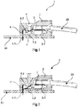
- the Figure 1 shows a first, closed operating state of an electrical conductor connection element 1 in a sectional illustration.
- the conductor connection element 1 is formed by a contact carrier 2 which is arranged at the end of a circuit card 30 on the surface thereof.
- a cable 20 is connected to the conductor connection element 1 and introduced into the contact carrier 2 from the right.
- a conductor receiving opening 7 is formed in the contact carrier 2, through which the cable 20 can be introduced into the contact carrier 2 from the right.
- a first contact element 3 is arranged in the contact carrier 2 of the conductor connection element 1.
- the first contact element 3 is provided in the interior of the contact carrier 2 and extends into the right-hand area in which the cable 20 is also inserted through the conductor receiving opening 7. In the right area, the first contact element 3 forms a first connection area 3.1.
- the cable 20 is inserted and connected into the first connection area 3.1 via the conductor receiving opening 7.
- the first connection area 3.1 of the first contact element 3 is designed as a cage clamp spring, a so-called cage clamp.
- the first contact element 3 is connected to a second contact element 4 in the contact carrier 2.
- the second contact element 4 also makes contact one end inside the contact carrier 2, the first contact element 3.
- the second end of the second contact element 4 forms a second connection area 4.1 outside the contact carrier 2.
- the second connection area 4.1 is received in the printed circuit card 30 and is electrically connected to it.
- the conductor connection element 1 thus establishes an electrical connection between the connected cable 20 and the circuit card 30 in the first, closed operating state shown.
- a further opening, a test opening 8, is provided in the contact carrier 2 above the first contact element 3.
- the test opening 8 enables access to a first contact area 3.2 of the first contact element 3 from outside the contact carrier 2.
- a separation point 6 is provided directly under the test opening 8.
- the separation point 6 is formed by the first contact area 3.2 of the first contact element 3 together with a second contact area 4.2 of the second contact element.
- the first contact area 3.2 and the second contact area 4.2 touch one another and are thus mechanically and electrically connected.
- the second contact area 3.2 of the first contact element 3 is designed to be movable at least in certain areas.
- the area of the separation point 6 is designed to be resilient and thus functions as a switch, specifically as an opening switch.
- the first contact element 3 and the second contact element 4 can be opened at the separation point 6 by flexible deformation of the first contact area 3.2.
- the movable part of the first contact area 3.2 springs upward so that the separation point 6 is closed.
- FIG. 2 a second, open test state of a conductor connection element 1 is shown in a sectional illustration.
- the separation point 6 is open and thus the electrical connection of the first contact element 3 and the second contact element 4 is separated.
- test pin is inserted into the test opening 8.
- the test pin protrudes through the test opening 8 into the contact carrier 2 up to the separation point 6.
- the movable part of the separation point 6 is reversibly deflected and pressed down by the test pin. Due to the flexible deformation of the first connection area 3.2 at the separation point 6, the first contact element 3 and the second contact element 4 are separated. The electrical connection between the first contact element 3 and the second contact element 4 is separated.
- a measurement of the contact element 3 with the connected cable 20 can be carried out with the test pin at the separation point 6.
- the measurement is not influenced by electrical components or voltages that are applied to the second connection area 4.1 of the second contact element 4 via the printed circuit card 30.
- the movable part of the first contact area 3.2 springs up again and closes the contact of the separation point 6.
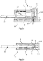
- the Figures 3a, 3b , 4a and 4b show a second embodiment of the present invention. They show Figures 3a and 4a each a sectional view through the electrical conductor connection element 1. The Figures 3b and 4b each show a further sectional view, the section being rotated by 90 ° through the electrical conductor connection element 1. The Figures 3a, 3b show the electrical conductor connection element 1 in a first, closed operating state, while the electrical conductor connection element 1 in FIG Figures 4a, 4b is shown in a second, open test state.
- the first connection area 3.1 of the first contact element 3 is designed as a so-called push-in contact. In an electrical conductor can be inserted and connected directly.
- the first contact element 3 has two opposing first contact areas 3.2.
- the second contact area 4.2 of the second contact element 4 is arranged between the first contact areas 3.2.
- the second contact element 4 is oriented perpendicular to the first contact element 3 and forms the second connection area 4.1 below the contact carrier 2.
- test pin is inserted into the contact carrier 2 via the test opening 8.
- the test pin is arranged between the two first contact areas 3.2 of the first contact element 3, so that the two first contact areas 3.2 are spread apart by the test pin.
- the strength of the test pin is designed in such a way that it allows sufficient spreading, ie lateral movement of the two first contact areas 3.2 away from the second contact area 4.2. Due to the deflected first contact areas 3.2, away from the second contact area 4.2, their mutual mechanical and electrical contact is released and the two contact points 6 are thus opened.
Landscapes
- Measuring Leads Or Probes (AREA)
- Coupling Device And Connection With Printed Circuit (AREA)
Claims (9)
- Elément de connexion de conducteur électrique (1) destiné à la mise en contact d'un conducteur électrique (20) sur une carte de circuits imprimés (30), présentant un support de contact (2), au moins un premier élément de contact (3) et au moins un deuxième élément de contact (4),
le premier élément de contact (3) étant reçu dans le support de contact (2) et relié de manière électriquement conductrice au deuxième élément de contact (4),
le premier élément de contact (3) étant prévu pour la mise en contact du conducteur électrique (20), et
le deuxième élément de contact (4) étant prévu pour la mise en contact de la carte de circuits imprimés (30),
le premier élément de contact (3) formant à l'intérieur du support de contact (2) une première zone de contact (3.2), et
le deuxième élément de contact (4) formant une deuxième zone de connexion (4.1) et à l'intérieur du support de contact (2) une deuxième zone de contact (4.2),
dans lequel
l'élément de connexion de conducteur électrique (1) présente au moins un point de séparation (6) qui est formé par la première zone de contact (3.2) et la deuxième zone de contact (4.2),
la connexion électriquement conductrice entre le premier élément de contact (3) et le deuxième élément de contact (4) peut être séparée par le point de séparation (6),
le premier élément de contact (3) présente une première zone de connexion (3.1) qui est disposée à proximité d'une ouverture de réception de conducteur (7) du support de contact (2) de sorte que le conducteur électrique (20) peut être introduit à travers l'ouverture de réception de conducteur (7) dans la première zone de connexion (3.1) et connecté à celle-ci,
le support de contact (2) présente en outre une ouverture de contrôle (8),
la première zone de contact (3.2) et la deuxième zone de contact (4.2) sont disposées dans le support de contact (2) au niveau de l'ouverture de contrôle (8),
et
le point de séparation (6) est disposé dans le support de contact (2) au niveau de l'ouverture de contrôle (8),
caractérisé en ce que la première zone de contact (3.2) du premier élément de contact (3) est réalisée sous la forme d'une partie mobile du point de séparation (6). - Elément de connexion de conducteur électrique (1) selon la revendication 1, caractérisé en ce que le premier élément de contact (3) dans la première zone de connexion (3.1) est réalisé sous la forme d'un contact à ressort ou d'un contact vissé ou d'un ressort de traction à cage ou d'un contact push-in et est prévu pour connecter un conducteur électrique (20).
- Elément de connexion de conducteur électrique (1) selon l'une quelconque des revendications 1 à 2, caractérisé en ce que le deuxième élément de contact (4) est réalisé dans la deuxième zone de connexion (4.1) sous la forme d'un contact push-in ou d'un contact à braser et est prévu pour la mise en contact d'une carte de circuits imprimés (30).
- Elément de connexion de conducteur électrique (1) selon la revendication 1, caractérisé en ce que la partie mobile du point de séparation (6) est composée, au moins par endroits, d'un matériau élastique.
- Elément de connexion de conducteur électrique (1) selon l'une quelconque des revendications 1 à 4, caractérisé en ce que plusieurs premiers éléments de contact (3), plusieurs deuxièmes éléments de contact (4) et plusieurs points de séparation (6) sont disposés dans le support de contact (2) en nombre égal.
- Elément de connexion de conducteur électrique (1) selon l'une quelconque des revendications 1 à 5, caractérisé en ce que le support de contact (2) est composé d'un matériau électriquement isolant.
- Elément de connexion de conducteur électrique (1) selon l'une quelconque des revendications 1 à 6, caractérisé en ce que l'élément de connexion de conducteur électrique (1) peut présenter un premier état de fonctionnement fermé et un deuxième état de contrôle ouvert, le point de séparation (6) étant fermé dans le premier état de fonctionnement fermé, et le point de séparation (6) étant ouvert dans le deuxième état de contrôle ouvert.
- Elément de connexion de conducteur électrique (1) selon l'une quelconque des revendications 1 à 7, caractérisé en ce que le premier élément de contact (3) est composé, au moins par endroits, de préférence la première zone de contact (3.2) du premier élément de contact (3), d'un métal faisant ressort.
- Elément de connexion de conducteur électrique (1) selon l'une quelconque des revendications 1 à 8, caractérisé en ce que la première zone de connexion (3.1) du premier élément de contact (3) est disposée à l'intérieur du support de contact (2), et en ce que la deuxième zone de connexion (4.1) du deuxième élément de contact (4) est disposée au moins en partie à - l'extérieur du support de contact (2).
Applications Claiming Priority (2)
| Application Number | Priority Date | Filing Date | Title |
|---|---|---|---|
| DE102016111565.7A DE102016111565B4 (de) | 2016-06-23 | 2016-06-23 | Elektrisches Leiteranschlusselement |
| PCT/DE2017/100419 WO2017220071A1 (fr) | 2016-06-23 | 2017-05-17 | Élément de connexion de conducteur électrique |
Publications (2)
| Publication Number | Publication Date |
|---|---|
| EP3476010A1 EP3476010A1 (fr) | 2019-05-01 |
| EP3476010B1 true EP3476010B1 (fr) | 2021-07-14 |
Family
ID=59014411
Family Applications (1)
| Application Number | Title | Priority Date | Filing Date |
|---|---|---|---|
| EP17728047.6A Active EP3476010B1 (fr) | 2016-06-23 | 2017-05-17 | Élément de connexion de conducteur électrique |
Country Status (5)
| Country | Link |
|---|---|
| US (1) | US20190157780A1 (fr) |
| EP (1) | EP3476010B1 (fr) |
| CN (1) | CN109417253B (fr) |
| DE (1) | DE102016111565B4 (fr) |
| WO (1) | WO2017220071A1 (fr) |
Families Citing this family (6)
| Publication number | Priority date | Publication date | Assignee | Title |
|---|---|---|---|---|
| DE102018101381A1 (de) * | 2018-01-23 | 2019-07-25 | Harting Electric Gmbh & Co. Kg | Steckverbinder mit Federkontakt |
| JP6811229B2 (ja) * | 2018-12-28 | 2021-01-13 | 矢崎総業株式会社 | コネクタ |
| EP4088347B1 (fr) * | 2020-01-09 | 2026-07-22 | Phoenix Contact Gmbh & Co. Kg | Dispositif électrique doté d'un dispositif de mise en contact pour une liaison libérable de sections de bus |
| DE102020119423A1 (de) * | 2020-07-23 | 2022-01-27 | Md Elektronik Gmbh | Löthilfsteil sowie Verfahren zur Befestigung eines Kabels an einer Leiterfläche |
| DE102021110661B4 (de) | 2021-04-27 | 2024-08-01 | HARTING Electronics GmbH | Elektrisches Leiteranschlusselement mit Kontaktfeder |
| WO2024227501A1 (fr) * | 2023-05-02 | 2024-11-07 | Harting Ag | Module enfichable de court-circuit |
Citations (1)
| Publication number | Priority date | Publication date | Assignee | Title |
|---|---|---|---|---|
| DE102011105157A1 (de) * | 2011-06-17 | 2012-12-20 | Phoenix Contact Gmbh & Co. Kg | Elektrisches Verbindungsmodul mit unterbrechbarem Stromkreis |
Family Cites Families (11)
| Publication number | Priority date | Publication date | Assignee | Title |
|---|---|---|---|---|
| DE2816776C2 (de) * | 1978-04-18 | 1980-02-21 | Siemens Ag, 1000 Berlin Und 8000 Muenchen | Schaltvorrichtung |
| JPS57501152A (fr) * | 1980-08-04 | 1982-07-01 | ||
| US5722850A (en) * | 1995-11-27 | 1998-03-03 | Molex Incorporated | Telecommunications connectors |
| US6439906B1 (en) * | 1999-03-25 | 2002-08-27 | Itt Manufacturing Enterprises, Inc. | Coax switch assembly |
| JP3427377B2 (ja) * | 2000-08-01 | 2003-07-14 | 日本航空電子工業株式会社 | スイッチ機能付きコネクタ |
| GB2390756A (en) * | 2002-07-11 | 2004-01-14 | Itt Mfg Enterprises Inc | PCB-mounted switch of a connector |
| DE202006020822U1 (de) | 2006-04-19 | 2010-08-05 | Phoenix Contact Gmbh & Co. Kg | Federkraftklemme |
| US8057246B2 (en) * | 2007-04-26 | 2011-11-15 | Tellabs Vienna, Inc. | Compact multiport test jack |
| DE102010048698B4 (de) | 2010-10-19 | 2014-12-18 | Wago Verwaltungsgesellschaft Mbh | Elektrische Verbindungsklemme |
| TWM462978U (zh) * | 2013-01-31 | 2013-10-01 | nai-qian Zhang | 可擴充晶片的連接器 |
| DE102015113734A1 (de) * | 2015-08-19 | 2017-02-23 | Wago Verwaltungsgesellschaft Mbh | Steckverbinder |
-
2016
- 2016-06-23 DE DE102016111565.7A patent/DE102016111565B4/de active Active
-
2017
- 2017-05-17 US US16/302,034 patent/US20190157780A1/en not_active Abandoned
- 2017-05-17 CN CN201780039002.3A patent/CN109417253B/zh active Active
- 2017-05-17 WO PCT/DE2017/100419 patent/WO2017220071A1/fr not_active Ceased
- 2017-05-17 EP EP17728047.6A patent/EP3476010B1/fr active Active
Patent Citations (1)
| Publication number | Priority date | Publication date | Assignee | Title |
|---|---|---|---|---|
| DE102011105157A1 (de) * | 2011-06-17 | 2012-12-20 | Phoenix Contact Gmbh & Co. Kg | Elektrisches Verbindungsmodul mit unterbrechbarem Stromkreis |
Also Published As
| Publication number | Publication date |
|---|---|
| CN109417253A (zh) | 2019-03-01 |
| DE102016111565A1 (de) | 2017-12-28 |
| US20190157780A1 (en) | 2019-05-23 |
| WO2017220071A1 (fr) | 2017-12-28 |
| EP3476010A1 (fr) | 2019-05-01 |
| DE102016111565B4 (de) | 2020-02-06 |
| CN109417253B (zh) | 2021-03-16 |
Similar Documents
| Publication | Publication Date | Title |
|---|---|---|
| EP2255412B1 (fr) | Dispositif de connexion électrique | |
| DE102013108383C5 (de) | Steckverbindermodul | |
| DE102016111565B4 (de) | Elektrisches Leiteranschlusselement | |
| EP2517305B1 (fr) | Dispositif de réception pour contacter l'âme d'un câble | |
| EP1830437A2 (fr) | Contact électrique | |
| EP1251590A2 (fr) | Borne électrique | |
| DE202011108572U1 (de) | Adapter und Set aus Reihenklemme und Adapter | |
| EP3698438B1 (fr) | Dispositif de mise en contact électrique | |
| DE202014010621U1 (de) | Steckverbinder | |
| DE102010034790B4 (de) | Kontaktträger für wenigstens eine Vorrichtung zur Kontaktierung eines elektrischen Leiters mit einer Leiterbahn | |
| EP2856561B1 (fr) | Borne de raccordement électrique | |
| DE202010011546U1 (de) | Vorrichtung zur Kontaktierung eines elektrischen Leiters mit einer Leiterbahn und Kontaktträger für eine solche Vorrichtung | |
| DE102016110951C5 (de) | Sicherheitsprüfspitze | |
| EP3443618B1 (fr) | Connecteur enfichable comportant un caoutchouc conducteur | |
| DE212019000423U1 (de) | Anschlussvorrichtung für elektrische Leiter | |
| EP3656022B1 (fr) | Connecteur à fiches doté d'un contact auxiliaire | |
| DE102018101381A1 (de) | Steckverbinder mit Federkontakt | |
| DE102006020045B4 (de) | Zwischenstecker und Verfahren zur Herstellung eines Zwischensteckers | |
| DE102010039957B4 (de) | Trennbuchsenanordnungen und Trennadapter mit einer Trägerplatte und einer oder mehreren darin angebrachten Trennbuchsen der Trennbuchsenanordnungen | |
| DE102015121447B4 (de) | Steckverbinder mit angeschlossenem Kabel | |
| DE202018104086U1 (de) | Steckverbinder mit Leitgummi | |
| DE102016122306B4 (de) | Anordnung zur Herstellung eines elektrischen Kontakts und Schaltanlage | |
| DE202015009061U1 (de) | Steckverbinder | |
| DE202013012807U1 (de) | Steckverbindermodul | |
| EP2823324B1 (fr) | Dispositif pour mesurer des composants électroniques |
Legal Events
| Date | Code | Title | Description |
|---|---|---|---|
| STAA | Information on the status of an ep patent application or granted ep patent |
Free format text: STATUS: UNKNOWN |
|
| STAA | Information on the status of an ep patent application or granted ep patent |
Free format text: STATUS: THE INTERNATIONAL PUBLICATION HAS BEEN MADE |
|
| PUAI | Public reference made under article 153(3) epc to a published international application that has entered the european phase |
Free format text: ORIGINAL CODE: 0009012 |
|
| STAA | Information on the status of an ep patent application or granted ep patent |
Free format text: STATUS: REQUEST FOR EXAMINATION WAS MADE |
|
| 17P | Request for examination filed |
Effective date: 20181122 |
|
| AK | Designated contracting states |
Kind code of ref document: A1 Designated state(s): AL AT BE BG CH CY CZ DE DK EE ES FI FR GB GR HR HU IE IS IT LI LT LU LV MC MK MT NL NO PL PT RO RS SE SI SK SM TR |
|
| AX | Request for extension of the european patent |
Extension state: BA ME |
|
| DAV | Request for validation of the european patent (deleted) | ||
| DAX | Request for extension of the european patent (deleted) | ||
| STAA | Information on the status of an ep patent application or granted ep patent |
Free format text: STATUS: EXAMINATION IS IN PROGRESS |
|
| 17Q | First examination report despatched |
Effective date: 20200401 |
|
| GRAP | Despatch of communication of intention to grant a patent |
Free format text: ORIGINAL CODE: EPIDOSNIGR1 |
|
| STAA | Information on the status of an ep patent application or granted ep patent |
Free format text: STATUS: GRANT OF PATENT IS INTENDED |
|
| INTG | Intention to grant announced |
Effective date: 20210316 |
|
| GRAS | Grant fee paid |
Free format text: ORIGINAL CODE: EPIDOSNIGR3 |
|
| GRAA | (expected) grant |
Free format text: ORIGINAL CODE: 0009210 |
|
| STAA | Information on the status of an ep patent application or granted ep patent |
Free format text: STATUS: THE PATENT HAS BEEN GRANTED |
|
| AK | Designated contracting states |
Kind code of ref document: B1 Designated state(s): AL AT BE BG CH CY CZ DE DK EE ES FI FR GB GR HR HU IE IS IT LI LT LU LV MC MK MT NL NO PL PT RO RS SE SI SK SM TR |
|
| REG | Reference to a national code |
Ref country code: GB Ref legal event code: FG4D Free format text: NOT ENGLISH |
|
| REG | Reference to a national code |
Ref country code: DE Ref legal event code: R096 Ref document number: 502017010904 Country of ref document: DE |
|
| REG | Reference to a national code |
Ref country code: IE Ref legal event code: FG4D Free format text: LANGUAGE OF EP DOCUMENT: GERMAN |
|
| REG | Reference to a national code |
Ref country code: AT Ref legal event code: REF Ref document number: 1411383 Country of ref document: AT Kind code of ref document: T Effective date: 20210815 |
|
| REG | Reference to a national code |
Ref country code: LT Ref legal event code: MG9D |
|
| REG | Reference to a national code |
Ref country code: NL Ref legal event code: MP Effective date: 20210714 |
|
| PG25 | Lapsed in a contracting state [announced via postgrant information from national office to epo] |
Ref country code: ES Free format text: LAPSE BECAUSE OF FAILURE TO SUBMIT A TRANSLATION OF THE DESCRIPTION OR TO PAY THE FEE WITHIN THE PRESCRIBED TIME-LIMIT Effective date: 20210714 Ref country code: FI Free format text: LAPSE BECAUSE OF FAILURE TO SUBMIT A TRANSLATION OF THE DESCRIPTION OR TO PAY THE FEE WITHIN THE PRESCRIBED TIME-LIMIT Effective date: 20210714 Ref country code: PT Free format text: LAPSE BECAUSE OF FAILURE TO SUBMIT A TRANSLATION OF THE DESCRIPTION OR TO PAY THE FEE WITHIN THE PRESCRIBED TIME-LIMIT Effective date: 20211115 Ref country code: NL Free format text: LAPSE BECAUSE OF FAILURE TO SUBMIT A TRANSLATION OF THE DESCRIPTION OR TO PAY THE FEE WITHIN THE PRESCRIBED TIME-LIMIT Effective date: 20210714 Ref country code: NO Free format text: LAPSE BECAUSE OF FAILURE TO SUBMIT A TRANSLATION OF THE DESCRIPTION OR TO PAY THE FEE WITHIN THE PRESCRIBED TIME-LIMIT Effective date: 20211014 Ref country code: BG Free format text: LAPSE BECAUSE OF FAILURE TO SUBMIT A TRANSLATION OF THE DESCRIPTION OR TO PAY THE FEE WITHIN THE PRESCRIBED TIME-LIMIT Effective date: 20211014 Ref country code: LT Free format text: LAPSE BECAUSE OF FAILURE TO SUBMIT A TRANSLATION OF THE DESCRIPTION OR TO PAY THE FEE WITHIN THE PRESCRIBED TIME-LIMIT Effective date: 20210714 Ref country code: RS Free format text: LAPSE BECAUSE OF FAILURE TO SUBMIT A TRANSLATION OF THE DESCRIPTION OR TO PAY THE FEE WITHIN THE PRESCRIBED TIME-LIMIT Effective date: 20210714 Ref country code: SE Free format text: LAPSE BECAUSE OF FAILURE TO SUBMIT A TRANSLATION OF THE DESCRIPTION OR TO PAY THE FEE WITHIN THE PRESCRIBED TIME-LIMIT Effective date: 20210714 Ref country code: HR Free format text: LAPSE BECAUSE OF FAILURE TO SUBMIT A TRANSLATION OF THE DESCRIPTION OR TO PAY THE FEE WITHIN THE PRESCRIBED TIME-LIMIT Effective date: 20210714 |
|
| PG25 | Lapsed in a contracting state [announced via postgrant information from national office to epo] |
Ref country code: PL Free format text: LAPSE BECAUSE OF FAILURE TO SUBMIT A TRANSLATION OF THE DESCRIPTION OR TO PAY THE FEE WITHIN THE PRESCRIBED TIME-LIMIT Effective date: 20210714 Ref country code: LV Free format text: LAPSE BECAUSE OF FAILURE TO SUBMIT A TRANSLATION OF THE DESCRIPTION OR TO PAY THE FEE WITHIN THE PRESCRIBED TIME-LIMIT Effective date: 20210714 Ref country code: GR Free format text: LAPSE BECAUSE OF FAILURE TO SUBMIT A TRANSLATION OF THE DESCRIPTION OR TO PAY THE FEE WITHIN THE PRESCRIBED TIME-LIMIT Effective date: 20211015 |
|
| REG | Reference to a national code |
Ref country code: DE Ref legal event code: R097 Ref document number: 502017010904 Country of ref document: DE |
|
| PG25 | Lapsed in a contracting state [announced via postgrant information from national office to epo] |
Ref country code: DK Free format text: LAPSE BECAUSE OF FAILURE TO SUBMIT A TRANSLATION OF THE DESCRIPTION OR TO PAY THE FEE WITHIN THE PRESCRIBED TIME-LIMIT Effective date: 20210714 |
|
| PLBE | No opposition filed within time limit |
Free format text: ORIGINAL CODE: 0009261 |
|
| STAA | Information on the status of an ep patent application or granted ep patent |
Free format text: STATUS: NO OPPOSITION FILED WITHIN TIME LIMIT |
|
| PG25 | Lapsed in a contracting state [announced via postgrant information from national office to epo] |
Ref country code: SM Free format text: LAPSE BECAUSE OF FAILURE TO SUBMIT A TRANSLATION OF THE DESCRIPTION OR TO PAY THE FEE WITHIN THE PRESCRIBED TIME-LIMIT Effective date: 20210714 Ref country code: SK Free format text: LAPSE BECAUSE OF FAILURE TO SUBMIT A TRANSLATION OF THE DESCRIPTION OR TO PAY THE FEE WITHIN THE PRESCRIBED TIME-LIMIT Effective date: 20210714 Ref country code: RO Free format text: LAPSE BECAUSE OF FAILURE TO SUBMIT A TRANSLATION OF THE DESCRIPTION OR TO PAY THE FEE WITHIN THE PRESCRIBED TIME-LIMIT Effective date: 20210714 Ref country code: EE Free format text: LAPSE BECAUSE OF FAILURE TO SUBMIT A TRANSLATION OF THE DESCRIPTION OR TO PAY THE FEE WITHIN THE PRESCRIBED TIME-LIMIT Effective date: 20210714 Ref country code: CZ Free format text: LAPSE BECAUSE OF FAILURE TO SUBMIT A TRANSLATION OF THE DESCRIPTION OR TO PAY THE FEE WITHIN THE PRESCRIBED TIME-LIMIT Effective date: 20210714 Ref country code: AL Free format text: LAPSE BECAUSE OF FAILURE TO SUBMIT A TRANSLATION OF THE DESCRIPTION OR TO PAY THE FEE WITHIN THE PRESCRIBED TIME-LIMIT Effective date: 20210714 |
|
| 26N | No opposition filed |
Effective date: 20220419 |
|
| PG25 | Lapsed in a contracting state [announced via postgrant information from national office to epo] |
Ref country code: IT Free format text: LAPSE BECAUSE OF FAILURE TO SUBMIT A TRANSLATION OF THE DESCRIPTION OR TO PAY THE FEE WITHIN THE PRESCRIBED TIME-LIMIT Effective date: 20210714 |
|
| REG | Reference to a national code |
Ref country code: CH Ref legal event code: PL |
|
| REG | Reference to a national code |
Ref country code: BE Ref legal event code: MM Effective date: 20220531 |
|
| PG25 | Lapsed in a contracting state [announced via postgrant information from national office to epo] |
Ref country code: MC Free format text: LAPSE BECAUSE OF FAILURE TO SUBMIT A TRANSLATION OF THE DESCRIPTION OR TO PAY THE FEE WITHIN THE PRESCRIBED TIME-LIMIT Effective date: 20210714 Ref country code: LU Free format text: LAPSE BECAUSE OF NON-PAYMENT OF DUE FEES Effective date: 20220517 Ref country code: LI Free format text: LAPSE BECAUSE OF NON-PAYMENT OF DUE FEES Effective date: 20220531 Ref country code: CH Free format text: LAPSE BECAUSE OF NON-PAYMENT OF DUE FEES Effective date: 20220531 |
|
| PG25 | Lapsed in a contracting state [announced via postgrant information from national office to epo] |
Ref country code: IE Free format text: LAPSE BECAUSE OF NON-PAYMENT OF DUE FEES Effective date: 20220517 |
|
| PG25 | Lapsed in a contracting state [announced via postgrant information from national office to epo] |
Ref country code: BE Free format text: LAPSE BECAUSE OF NON-PAYMENT OF DUE FEES Effective date: 20220531 |
|
| P01 | Opt-out of the competence of the unified patent court (upc) registered |
Effective date: 20230603 |
|
| REG | Reference to a national code |
Ref country code: AT Ref legal event code: MM01 Ref document number: 1411383 Country of ref document: AT Kind code of ref document: T Effective date: 20220517 |
|
| PG25 | Lapsed in a contracting state [announced via postgrant information from national office to epo] |
Ref country code: AT Free format text: LAPSE BECAUSE OF NON-PAYMENT OF DUE FEES Effective date: 20220517 |
|
| PG25 | Lapsed in a contracting state [announced via postgrant information from national office to epo] |
Ref country code: HU Free format text: LAPSE BECAUSE OF FAILURE TO SUBMIT A TRANSLATION OF THE DESCRIPTION OR TO PAY THE FEE WITHIN THE PRESCRIBED TIME-LIMIT; INVALID AB INITIO Effective date: 20170517 |
|
| PG25 | Lapsed in a contracting state [announced via postgrant information from national office to epo] |
Ref country code: MK Free format text: LAPSE BECAUSE OF FAILURE TO SUBMIT A TRANSLATION OF THE DESCRIPTION OR TO PAY THE FEE WITHIN THE PRESCRIBED TIME-LIMIT Effective date: 20210714 Ref country code: CY Free format text: LAPSE BECAUSE OF FAILURE TO SUBMIT A TRANSLATION OF THE DESCRIPTION OR TO PAY THE FEE WITHIN THE PRESCRIBED TIME-LIMIT Effective date: 20210714 |
|
| PG25 | Lapsed in a contracting state [announced via postgrant information from national office to epo] |
Ref country code: MT Free format text: LAPSE BECAUSE OF FAILURE TO SUBMIT A TRANSLATION OF THE DESCRIPTION OR TO PAY THE FEE WITHIN THE PRESCRIBED TIME-LIMIT Effective date: 20210714 |
|
| PG25 | Lapsed in a contracting state [announced via postgrant information from national office to epo] |
Ref country code: TR Free format text: LAPSE BECAUSE OF FAILURE TO SUBMIT A TRANSLATION OF THE DESCRIPTION OR TO PAY THE FEE WITHIN THE PRESCRIBED TIME-LIMIT Effective date: 20210714 |
|
| PGFP | Annual fee paid to national office [announced via postgrant information from national office to epo] |
Ref country code: GB Payment date: 20260525 Year of fee payment: 10 |
|
| PGFP | Annual fee paid to national office [announced via postgrant information from national office to epo] |
Ref country code: DE Payment date: 20260522 Year of fee payment: 10 |
|
| PGFP | Annual fee paid to national office [announced via postgrant information from national office to epo] |
Ref country code: FR Payment date: 20260521 Year of fee payment: 10 |