EP3476015B1 - Leistungsverstärker - Google Patents
Leistungsverstärker Download PDFInfo
- Publication number
- EP3476015B1 EP3476015B1 EP17731918.3A EP17731918A EP3476015B1 EP 3476015 B1 EP3476015 B1 EP 3476015B1 EP 17731918 A EP17731918 A EP 17731918A EP 3476015 B1 EP3476015 B1 EP 3476015B1
- Authority
- EP
- European Patent Office
- Prior art keywords
- voltage
- power amplification
- amplification device
- discharge electrode
- electric arc
- Prior art date
- Legal status (The legal status is an assumption and is not a legal conclusion. Google has not performed a legal analysis and makes no representation as to the accuracy of the status listed.)
- Active
Links
Images

Classifications
-
- H—ELECTRICITY
- H01—ELECTRIC ELEMENTS
- H01T—SPARK GAPS; OVERVOLTAGE ARRESTERS USING SPARK GAPS; SPARKING PLUGS; CORONA DEVICES; GENERATING IONS TO BE INTRODUCED INTO NON-ENCLOSED GASES
- H01T2/00—Spark gaps comprising auxiliary triggering means
- H01T2/02—Spark gaps comprising auxiliary triggering means comprising a trigger electrode or an auxiliary spark gap
-
- H—ELECTRICITY
- H01—ELECTRIC ELEMENTS
- H01T—SPARK GAPS; OVERVOLTAGE ARRESTERS USING SPARK GAPS; SPARKING PLUGS; CORONA DEVICES; GENERATING IONS TO BE INTRODUCED INTO NON-ENCLOSED GASES
- H01T1/00—Details of spark gaps
- H01T1/20—Means for starting arc or facilitating ignition of spark gap
- H01T1/22—Means for starting arc or facilitating ignition of spark gap by the shape or the composition of the electrodes
-
- H—ELECTRICITY
- H01—ELECTRIC ELEMENTS
- H01T—SPARK GAPS; OVERVOLTAGE ARRESTERS USING SPARK GAPS; SPARKING PLUGS; CORONA DEVICES; GENERATING IONS TO BE INTRODUCED INTO NON-ENCLOSED GASES
- H01T15/00—Circuits specially adapted for spark gaps, e.g. ignition circuits
-
- H—ELECTRICITY
- H03—ELECTRONIC CIRCUITRY
- H03K—PULSE TECHNIQUE
- H03K3/00—Circuits for generating electric pulses; Monostable, bistable or multistable circuits
- H03K3/02—Generators characterised by the type of circuit or by the means used for producing pulses
- H03K3/53—Generators characterised by the type of circuit or by the means used for producing pulses by the use of an energy-accumulating element discharged through the load by a switching device controlled by an external signal and not incorporating positive feedback
- H03K3/537—Generators characterised by the type of circuit or by the means used for producing pulses by the use of an energy-accumulating element discharged through the load by a switching device controlled by an external signal and not incorporating positive feedback the switching device being a spark gap
-
- H—ELECTRICITY
- H01—ELECTRIC ELEMENTS
- H01T—SPARK GAPS; OVERVOLTAGE ARRESTERS USING SPARK GAPS; SPARKING PLUGS; CORONA DEVICES; GENERATING IONS TO BE INTRODUCED INTO NON-ENCLOSED GASES
- H01T1/00—Details of spark gaps
- H01T1/20—Means for starting arc or facilitating ignition of spark gap
Definitions
- the present invention relates to the field of power electronics and relates more particularly to a power amplification device.
- a power amplification device finds its application in particular in the context of a test bench for materials under high pressure, of a test bench for a load or else in the context of a seismic application of a well bottom.
- power amplification devices which make it possible to transfer a very high current under very high voltage between two electrodes in a fraction of a second, the bias voltage between the two electrodes being supplied by an external power supply. , for example between 5 and 40 kV.
- Such power amplification devices are generally used in applications such as the Marx generator or other very high voltage assembly, for example in association with capacitors making it possible to store electrical energy, and to restore it under the a very high intensity current under very high voltage.
- a gas power amplification device is triggered independently.
- such a device comprises two electrodes spaced apart by an interval and arranged opposite one another in a gaseous medium or in a vacuum.
- An example of a gas power amplification device is described in the request. FR2999350A1 filed by the Applicant.
- a threshold value is a function of the geometry of the electrodes, the distance between the electrodes and the pressure of the medium in which the electrodes are placed.
- Such a device is of simple design but has the drawback of being only unreliable since in a gaseous medium or in a vacuum, the trigger value actually follows a Gaussian distribution around the desired threshold value.
- a triggered power amplification device uses means to trigger the generation of the electric arc between two main electrodes.
- a type known triggered power amplification device called trigatron
- uses a third electrode, called trigger electrode positioned in the vicinity of the interval separating the two main electrodes, for example orthogonally to the two main electrodes or co-axially to the one of them, to trigger the generation of the electric arc.
- the figure 1 schematically illustrates an example of a triggered power amplification device 1 comprising two main electrodes 2 and 3 and a trigger electrode 4.
- the trigger electrode 4 is connected to an external current generator 5 delivering a high voltage pulse (from the 'order of a few kV maximum) via a cable 6 the "low voltage" power supply while the main electrodes 2 and 3 are connected to an external current generator 7 delivering a high voltage (of a few kV or tens of kV) by a 8 high voltage power cable.
- the voltage applied to the trigger electrode 4 makes it possible to create an ionized air channel A1 in the space E between the two main electrodes 2, 3.
- This ionization facilitates the creation of a second electric arc A2 (or main electric arc) between the two main electrodes 2, 3, thus ensuring the passage of current.
- a power amplification device comprising two main electrodes arranged facing each other between which an electric arc develops by the application of a voltage to a trigger electrode mounted coaxially inside one of the two main electrodes.
- a triggered power amplification device is significantly more stable than a gas powered amplification device since it always trips at the same threshold value.
- a triggered power amplification device is difficult to adjust, which has a first drawback.
- the use of an external current generator to deliver a pulse to the triggering electrode presents an important limitation for on-board use, in particular in the case of a wellbore in which it is then necessary to make lower both the power cable for the trigger electrode in addition to the high voltage power cable for the main electrodes.
- certain applications such as the Marx generator may require the use of numerous triggered power amplification devices put in association, for example in a parallel circuit, with numerous capacitors.
- US 2004/179317 A1 states a power amplification device comprising a switching module, said switching module comprising a first discharge electrode and a second discharge electrode, disposed facing each other at a predetermined fixed distance defining a space for generation of an electric arc, and a trigger means located in the vicinity of said space and being configured to trigger the formation of said electric arc in said space.
- US 2007/165351 A1 sets out a method for generating an electric arc between a first discharge electrode and a second discharge electrode, disposed facing each other at a predetermined fixed distance defining a space for generating an electric arc, the generation of said electric arc being triggered by a trigger means located in the vicinity of said space, said method comprising the steps of: detection of an activation event, generation of an activation signal when an activation event has been detected, generation of an impulse command when an activation signal has been generated, and transmission of said impulse command generated to the triggering means so that the triggering means triggers the formation of an electric arc between the first discharge electrode and the second discharge electrode.
- the object of the present invention is to remedy these drawbacks at least in part by proposing a simple, reliable and efficient solution for a power amplification device which does not require complex external wiring in order to be able to be used in an on-board application, for example in the bottom well for a seismic application.
- the invention firstly relates to a power amplification device able to be supplied by a single input voltage and comprising a switching module, said switching module comprising a first discharge electrode and a second discharge electrode, disposed facing each other at a predetermined fixed distance defining a space for generating an electric arc, and a trigger means located in the vicinity of said space and being configured to trigger the formation of said electric arc in said space, said power amplification device being remarkable in that it comprises a trigger module comprising a voltage converter configured to convert the input voltage into a first supply voltage and into a second voltage power supply, a detection sub-module configured to detect an activation event, to generate, by pa From the first supply voltage, an activation signal when an activation event has been detected, a pulse generator configured to generate, from the second supply voltage, a pulse command when signal activation was generated, and to transmit the impulse command generated by the triggering means of the switching module so that the triggering means triggers the formation of an electric arc between the first discharge electrode and the second discharge electrode
- the input voltage is a high voltage whose value is greater than 1 kV, preferably between 5 and 40 kV.
- the power amplification device according to the invention is a self-triggered device which operates with a single input voltage and therefore a single external power cable, which makes it possible to reduce the number of cables and therefore does not require connection with the outside to control the triggering means or additional battery, its power supply being advantageously controlled by the second voltage.
- the dimensions of the power amplification device according to the invention can advantageously be reduced so as to be embedded in a box, for example to easily lower it into a well.
- the module triggering of the device according to the invention can be used with most known configurations and types of discharge electrodes and triggering means.
- the device according to the invention also allows stability and precision of the triggering of the electric arc regardless of the geometry of the electrodes, the distance between the first electrode and the second electrode or the pressure of the medium, which increases the duration of use of the power amplification device without maintenance operation.
- the trigger module comprises a voltage converter, a detection submodule and a pulse generator, the voltage converter being configured to convert the input voltage into the first supply voltage and into the second supply voltage, the first voltage supplying the detection module, the second voltage supplying the pulse generator.
- the trigger module is configured to compare the value of the input voltage with a predetermined threshold value and generate the activation signal when the value of the input voltage is greater than or equal at the predetermined threshold value.
- a voltage criterion to trigger the electric arc makes it possible to make the device independent of the time and in particular of the charging time of the capacitors of the current generator supplying it with the input voltage.
- the detection sub-module is configured to receive the input voltage, compare the value of the input voltage with a predetermined threshold value and, when the value of the input voltage is greater than or equal to the predetermined threshold value, generating the activation signal from the first supply voltage and sending said activation signal to the pulse generator.
- the delay between the detection of the predetermined threshold value by the detection sub-module and the start of the current transfer by the triggering means is less than 100 ⁇ s.
- the trigger module comprises a clock and is configured to generate the activation signal periodically from said clock.
- the detection sub-module comprises the clock and is configured to periodically generate the activation signal from the first supply voltage and to send said activation signal to the pulse generator.
- the trigger means is in the form of a trigger electrode.
- the value of the first voltage is between 1 and 15 V.
- the activation signal is in the form of a voltage step whose amplitude is less than 15 V.
- the value of the amplitude of the voltage step is equal to the value of the first voltage.
- the value of the second voltage is of the order of several hundred volts, preferably of the order of 500 V.
- the pulse control is in the form of a voltage pulse signal whose duration is between 0.5 and 10 ⁇ s.
- the voltage pulse signal reaches a maximum value of the order of 20 kV allowing the triggering means to trigger the formation of the electric arc between the first discharge electrode and the second electrode. unloading.
- the invention also relates to a power amplification system comprising a power amplification device as presented above and a current generator delivering a voltage of several kilovolts, preferably between 5 and 40 kV, at the input of said device. power amplification.
- the method comprises a step of comparing the value of the input voltage with a predetermined threshold value and the activation signal is generated when the value of the input voltage is greater than or equal to the predetermined threshold value.
- the trigger module comprising a clock
- the activation signal is generated periodically from said clock.
- the power amplification device is a switching device of the closing switch type comprising two remote electrodes, called discharge electrodes, separated by a dielectric (gas, vapor, vacuum ...), between which forms an electric arc when the potential difference between the electrodes is greater than a threshold value.
- this threshold value is greater than a few kV (kilo Volts), and the operating voltage of the device (voltage applied to the power amplification device, i.e. the potential difference between its electrodes), can go up to 1 MV.
- Such a power amplification device makes it possible to transfer a quantity of electric charges ranging from a few milli-Coulombs to several hundreds of Coulombs, corresponding to an electric current passing through the power amplification device of intensity between 1 kA and 1 MY.
- a current generator and in particular with one or more capacitors capable of accumulating the quantities of electric charges mentioned above, this device can be used for various applications.
- the power amplification device according to the invention is a self-triggered power amplification device which is only supplied by a single current generator.
- the device according to the invention can be used to supply a test bench for materials under high pressure or any other load sequentially or else in a drilling well for a seismic purpose, for example to stimulate the oil production.
- Each operation of discharging the capacitor and transferring to the load, by the power amplification device, the electrical charges initially accumulated in the capacitor, is called a shot.
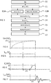
- This system 9 comprises a power amplification device 10 and a current generator 7 delivering a single input voltage Ue to the device 10 via a high voltage power cable 8.
- the device 10 comprises a switching module 100 and a trigger module 200.
- the switching module 100 comprises a first discharging electrode 110 and a second discharging electrode 120 arranged opposite one another at a predetermined fixed distance D and defining a space E for generating an electric arc A2 from of the input voltage Ue.
- the current generator 7 comprises one or more capacitors which charge over time so as to deliver an increasing voltage Ue which can reach several kV, for example between 5 and 40 kV, until the formation of the arc. electric A2 between the first discharge electrode 110 and a second discharge electrode 120 as will be explained below.
- the switching module 100 then comprises a triggering means located in the vicinity of the space E and which is configured to trigger the formation of an electric arc A2 in said space E.
- this triggering means is presented under the form of a third electrode, called trigger electrode 130.
- This trigger electrode 130 makes it possible to create an ionized air channel A1 in space E facilitating the formation of electric arc A2 (called main electric arc) between the first discharge electrode 110 and the second discharge electrode 120 then ensuring the passage of current.
- the electric charges propagate from the connection end of the first discharge electrode 110 towards the end of the second discharge electrode 120 through the space E.
- the first discharge electrode 110 and the second discharge electrode 120 are preferably of generally hollow cylindrical shape, symmetrical in revolution.
- the first discharge electrode 110 and the second discharge electrode 120 are aligned "end to end", that is to say arranged so that their respective longitudinal axes (not shown) coincide and that they have axial ends (not shown), called closure ends, distant from a predetermined fixed distance D, for example between 1 and 15 mm approximately and facing in the axial direction (direction of the axes of symmetry).
- connection ends are each connected to a connector (not shown) for the integration of the power amplification device in an electrical circuit.
- one of the connectors is used to connect the current generator 7 and the other to connect a load for example.
- the trigger module 200 is connected to the switching module 100 in order to control it.
- the trigger module 200 is configured to convert the input voltage Ue into a first supply voltage BT1 and into a second supply voltage BT2, to detect an activation event and to generate, from the first voltage power supply BT1, an activation signal S act when an activation event has been detected.
- the trigger module 200 comprises a voltage converter 210, a detection sub-module 220 and a pulse generator 230.
- the voltage converter 210 is configured to convert the input voltage Ue supplied by the external current generator 7 into a first supply voltage BT1 and into a second supply voltage BT2.
- the first supply voltage BT1 preferably of the order of a few volts (for example 5 V)
- the second supply voltage BT2 preferably of the order of a few hundred volts (for example 500 V)
- the detection sub-module 220 is configured to receive the input voltage Ue supplied by the current generator 7, to compare the value of said input voltage Ue with a predetermined threshold value Uc and , when the value of the input voltage Ue is greater than or equal to the predetermined threshold value Uc, to generate an activation signal S act from the first supply voltage BT1 and send said activation signal S act to the pulse generator 230.
- the detection of the exceeding of the predetermined threshold value Uc by the input voltage Ue constitutes the activation event.
- the delay ⁇ T1 between the detection of the predetermined threshold value by the detection sub-module 220 and the start of the current transfer by the triggering electrode 130 is less than 100 ⁇ s.
- the detection sub-module 220 comprises a clock (not shown) and is configured to generate the activation signal S act periodically from said clock and to send said signal activation S act to the pulse generator 230.
- the activation event corresponds to the start of the periodic interval during which the activation signal S act is generated and sent. Since such a clock is known per se, it will not be further detailed here.
- the activation signal S act can be a TTL (Transistor-Transistor Logic) signal known per se, corresponding to a voltage step whose amplitude is equal to the first supply voltage BT1, for example 5 V, as illustrated to the figure 5 .
- TTL Transistor-Transistor Logic
- the pulse generator 230 is configured to receive an activation signal S act from the detection sub-module 220, to generate a pulse command C i from the second supply voltage BT2 following the reception of said signal activation S act and to transmit said impulse command C i to the trigger electrode 130 in order to trigger the generation of an electric arc between the first discharge electrode 100 and the second discharge electrode 200.
- the current generator 7 generates in a step E0 a current which defines an input voltage Ue of the power amplification device 10.
- This input voltage Ue is preferably between 5 and 40 kV.
- This input voltage Ue generated by the charge of the capacitor (s) of the current generator 7, increases over time until it reaches a maximum value Umax for which an electric arc A2 is formed between the first electrode 110 and the second electrode 120 causing the discharge of the capacitors of the current generator 7 and the fall of the input voltage Ue to zero.
- the converter 210 converts the input voltage Ue delivered by the current generator 7, on the one hand, into a first supply voltage BT1 of the detection sub-module 220 and, on the other hand, in a second supply voltage BT2 of the pulse generator 230.
- the first supply voltage BT1 is of the order of 5 V
- the second supply voltage BT2 is of the order of 500 V.
- the detection sub-module 220 which also receives the input voltage Ue, constantly compares, in a step E2A, the value of said input voltage Ue with a predetermined threshold value Uc, for example of 30 kV.
- a predetermined threshold value Uc for example of 30 kV.
- the detection sub-module 220 When the value of the input voltage Ue reaches (ie equal) the predetermined threshold value Uc, the detection sub-module 220 generates, in a step E3, an activation signal S act from the first voltage of power supply BT1 and transmits it to the pulse generator 230 in a step E4.
- this activation signal S act is in this example in the form of a voltage step of 5 V, corresponding to the value of the first supply voltage BT1.
- the detection sub-module 220 detects the start of the periodic time interval generated by the clock in a step E2B and generates then periodically the activation signal S act in a step E3 and then transmits it to the pulse generator 230 in a step E4.
- the voltage for which the electric arc forms can be defined by adapting the charging time of the capacitors so that it corresponds to the period of the clock.
- the pulse generator 230 when it receives this activation signal S ac t, the pulse generator 230 in turn generates, in a step E5, a pulse command Ci from the second supply voltage BT2 generated and supplied by the converter 210. This impulse command is transmitted, in a step E6, to the triggering electrode 130.
- the impulse command C i is in the form of a voltage impulse signal starting at the end of the delay ⁇ T1, the start of this voltage peak being detected when the voltage exceeds a minimum threshold value.
- This minimum threshold value can be equal to 10% of the maximum voltage, ie for example a minimum threshold value of 0.1 V.
- This delay ⁇ T1 corresponds to the time elapsed between the detection of the threshold Uc and the generation of the triggering pulse Ci.
- the pulse signal increases, during a delay ⁇ T2 comprised in this example between 0.5 and 10 ⁇ s after it starts, to a maximum value of 20 kV.
- an ionized air channel A1 is created between the first discharge electrode 110 and the second discharge electrode 120.
- the main electric arc A2 is generated, in a step E7, between the first discharge electrode 110 and the second discharge electrode 120.
- the input voltage Ue then instantly drops to zero, as does the voltage value of the activation signal S act (end of the voltage step) and the voltage value of the impulse control C i .
- the formation of the electric arc A2 generates an oscillating output current I out , the value of which can be in this example between 10 and 30 kA.
- the invention therefore makes it possible to trigger a shot using a trigger electrode 130 without using an external voltage supply, the supply of the trigger generator 230 being produced by the second voltage BT2 generated by the voltage converter 210.
- the device triggered power amplification 10 according to the invention therefore requires only one external power supply (current generator 7), which reduces the number of cables and allows it to be easily used in places of difficult access such as boreholes, while allowing firing to be triggered at a constant threshold value thanks to the triggering electrode.
Landscapes
- Chemical & Material Sciences (AREA)
- Engineering & Computer Science (AREA)
- Combustion & Propulsion (AREA)
- Plasma Technology (AREA)
Claims (10)
- Leistungsverstärker (10), der imstande ist, von einer einzigen Eingangsspannung versorgt zu werden und ein Schaltmodul (100) umfasst, wobei das Schaltmodul (100) eine erste Entladeelektrode (110) und eine zweite Entladeelektrode (120) umfasst, die in einem vorher festgelegten festen Abstand (D) einander zugewandt angeordnet sind, der einen Raum (E) für das Erzeugen eines Lichtbogens (A2) definiert, und ein Auslösemittel (130), das sich in der Nähe des Raums (E) befindet und konfiguriert ist, um die Bildung des Lichtbogens (A2) in dem Raum (E) auszulösen, wobei der Leistungsverstärker (10) dadurch gekennzeichnet, dass er ein Auslösemodul (200) umfasst, umfassend:- einen Spannungswandler (210), der konfiguriert ist, um die Eingangsspannung (Ue) in eine erste Versorgungsspannung (BT1) und in eine zweite Versorgungsspannung (BT2) zu wandeln,- ein Detektions-Untermodul (220), das konfiguriert ist, um:∘ ein Aktivierungsereignis zu ermitteln,∘ auf der Basis der ersten Versorgungsspannung (BT1) ein Aktivierungssignal (Sact) zu generieren, wenn ein Aktivierungsereignis ermittelt wurde,- einen Impulsgenerator (230), der konfiguriert ist, um:∘ auf der Basis der zweiten Versorgungsspannung (BT2) einen Impulsbefehl (Ci) zu generieren, wenn ein Aktivierungssignal generiert wurde, und∘ den generierten Impulsbefehl (Ci) an das Auslösemittel (130) des Schaltmoduls (100) zu übertragen, damit das Auslösemittel (130) die Bildung eines Lichtbogens (A2) zwischen der ersten Entladeelektrode (110) und der zweiten Entladeelektrode (120) auslöst.
- Leistungsverstärker (10) nach Anspruch 1, dadurch gekennzeichnet, dass das Auslösemodul konfiguriert ist, um den Wert der Eingangsspannung (Ue) mit einem vorher festgelegten Grenzwert (Uc) zu vergleichen und das Aktivierungssignal (Sact) zu generieren, wenn der Wert der Eingangsspannung (Ue) größer oder gleich dem vorher festgelegten Grenzwert (Uc) ist.
- Leistungsverstärker (10) nach Anspruch 1, dadurch gekennzeichnet, dass das Auslösemodul eine Uhr umfasst und konfiguriert ist, um das Aktivierungssignal (Sact) periodisch auf der Basis der Uhr zu generieren.
- Leistungsverstärker (10) nach einem der Ansprüche 1 bis 3, dadurch gekennzeichnet, dass der Wert der ersten Spannung (BT1) zwischen 1 und 10 V liegt.
- Leistungsverstärker (10) nach einem der Ansprüche 1 bis 4, dadurch gekennzeichnet, dass das Aktivierungssignal (Sact) in Form einer Spannungsstufe vorliegt, deren Amplitude gleich dem Wert der ersten Spannung (BT1) ist.
- Leistungsverstärker (10) nach einem der Ansprüche 1 bis 5, dadurch gekennzeichnet, dass der Wert der zweiten Spannung (BT2) in der Größenordnung von mehreren Hundert Volt liegt.
- Leistungsverstärker (10) nach einem der Ansprüche 1 bis 6, dadurch gekennzeichnet, dass der Impulsbefehl (Ci) in Form eines Spannungsimpulssignals vorliegt, dessen Dauer zwischen 0,5 und 10 s beträgt.
- Leistungsverstärker (10) nach Anspruch 7, dadurch gekennzeichnet, dass das Spannungsimpulssignal einen maximalen Wert in der Größenordnung von 20 kV erreicht, was es dem Auslösemittel (130) gestattet, die Bildung des Lichtbogens (A2) zwischen der ersten Entladeelektrode (110) und der zweiten Entladeelektrode (120) auszulösen.
- System (9) zur Leistungsverstärkung (10), umfassend einen Leistungsverstärker (10) nach einem der vorangehenden Ansprüche und einen Stromgenerator (7), der eine Spannung (Ue) zwischen 5 und 40 kV am Eingang des Leistungsverstärkers (10) bereitstellt.
- Verfahren zum Erzeugen eines Lichtbogens (A2) zwischen einer ersten Entladeelektrode (110) und einer zweiten Entladeelektrode (120), die in einem vorher festgelegten festen Abstand (D) einander zugewandt angeordnet sind, der einen Raum (E) des Erzeugens eines Lichtbogens (A2) definiert, wobei das Erzeugen des Lichtbogens (A2) durch ein Auslösemittel (130) ausgelöst wird, das sich in der Nähe des Raums (E) befindet, wobei das Verfahren von einem Leistungsverstärker (10) nach Anspruch 1 durchgeführt wird, der mit einer Eingangsspannung (Ue) versorgt wird, umfassend die Schritte:- Umwandeln (E1) der Eingangsspannung (Ue) in eine erste Versorgungsspannung (BT1) und in eine zweite Versorgungsspannung (BT2),- Ermitteln (E2A, E2B) eines Aktivierungsereignisses,- Generieren (E3), auf der Basis der ersten Versorgungsspannung (BT1), eines Aktivierungssignals (Sact), wenn ein Aktivierungsereignis ermittelt wurde,- Generieren (E5), auf der Basis der zweiten Versorgungsspannung (BT2), eines Impulsbefehls (Ci), wenn ein Aktivierungssignal generiert wurde, und- Übertragen (E6) des generierten Impulsbefehls (Ci) an das Auslösemittel (130), damit das Auslösemittel (130) die Bildung eines Lichtbogens (A2) zwischen der ersten Entladeelektrode (110) und der zweiten Entladeelektrode (120) auslöst.
Applications Claiming Priority (2)
| Application Number | Priority Date | Filing Date | Title |
|---|---|---|---|
| FR1656005A FR3053171B1 (fr) | 2016-06-28 | 2016-06-28 | Dispositif d'amplification de puissance |
| PCT/EP2017/065581 WO2018001905A1 (fr) | 2016-06-28 | 2017-06-23 | Dispositif d'amplification de puissance |
Publications (2)
| Publication Number | Publication Date |
|---|---|
| EP3476015A1 EP3476015A1 (de) | 2019-05-01 |
| EP3476015B1 true EP3476015B1 (de) | 2020-05-13 |
Family
ID=57233579
Family Applications (1)
| Application Number | Title | Priority Date | Filing Date |
|---|---|---|---|
| EP17731918.3A Active EP3476015B1 (de) | 2016-06-28 | 2017-06-23 | Leistungsverstärker |
Country Status (5)
| Country | Link |
|---|---|
| US (1) | US10483723B2 (de) |
| EP (1) | EP3476015B1 (de) |
| CA (1) | CA3029365C (de) |
| FR (1) | FR3053171B1 (de) |
| WO (1) | WO2018001905A1 (de) |
Families Citing this family (1)
| Publication number | Priority date | Publication date | Assignee | Title |
|---|---|---|---|---|
| FR3084546B1 (fr) * | 2018-07-24 | 2021-11-05 | Adm28 S Ar L | Dispositif de decharge electrique impulsionnelle |
Family Cites Families (9)
| Publication number | Priority date | Publication date | Assignee | Title |
|---|---|---|---|---|
| US4558280A (en) * | 1983-04-01 | 1985-12-10 | Cooper Industries, Inc. | Ignition secondary analyzer |
| US4631451A (en) * | 1983-11-18 | 1986-12-23 | Ford Motor Company | Blast gap ignition system |
| CA1289171C (en) | 1987-07-20 | 1991-09-17 | Noranda Inc. | Electromechanically triggered spark gap switch |
| US5043636A (en) * | 1989-07-28 | 1991-08-27 | Summit Technology, Inc. | High voltage switch |
| JP2001297854A (ja) * | 2000-04-14 | 2001-10-26 | Keyence Corp | コロナ放電装置 |
| WO2003005392A1 (en) * | 2001-06-29 | 2003-01-16 | Korea Atomic Energy Research Institute | Self bouncing arc switch |
| FR2864711B1 (fr) * | 2003-12-30 | 2006-04-21 | Soule Protection Surtensions | Dispositif de protection contre les surtensions avec eclateurs en parallele a declenchement simultane |
| DE102004002582A1 (de) * | 2004-01-13 | 2005-08-04 | Siemens Ag | Optisch gezündete Funkenstrecke |
| FR2999350B1 (fr) | 2012-12-07 | 2015-01-02 | Ene29 S A R L | Eclateur de commutation coaxial |
-
2016
- 2016-06-28 FR FR1656005A patent/FR3053171B1/fr not_active Expired - Fee Related
-
2017
- 2017-06-23 US US16/308,924 patent/US10483723B2/en active Active
- 2017-06-23 EP EP17731918.3A patent/EP3476015B1/de active Active
- 2017-06-23 CA CA3029365A patent/CA3029365C/fr active Active
- 2017-06-23 WO PCT/EP2017/065581 patent/WO2018001905A1/fr not_active Ceased
Non-Patent Citations (1)
| Title |
|---|
| None * |
Also Published As
| Publication number | Publication date |
|---|---|
| FR3053171B1 (fr) | 2018-07-06 |
| WO2018001905A1 (fr) | 2018-01-04 |
| FR3053171A1 (fr) | 2017-12-29 |
| CA3029365C (fr) | 2024-06-04 |
| CA3029365A1 (fr) | 2018-01-04 |
| EP3476015A1 (de) | 2019-05-01 |
| US20190148919A1 (en) | 2019-05-16 |
| US10483723B2 (en) | 2019-11-19 |
Similar Documents
| Publication | Publication Date | Title |
|---|---|---|
| EP0086136B1 (de) | Generator elektromagnetischer Hochspannungsimpulse | |
| EP0215707A1 (de) | Spannungsschaltvorrichtung | |
| FR3019700A1 (fr) | Systeme et procede de generation de hautes puissances pulsees a alimentation unique | |
| FR2925214A1 (fr) | Court-circuit pyrotechnique a contacts electrique auto-serrant et ensemble de protection contre les arcs internes comportant un tel court-circuiteur | |
| CA2941927C (fr) | Sonde de generation d'ondes sismiques | |
| FR3102754A1 (fr) | Architecture propulsive hybride et aéronef comportant une telle architecture | |
| CA3029365C (fr) | Dispositif d'amplification de puissance | |
| EP3051101B1 (de) | Hochenergie-zündunganlage, insbesondere für gasturbine | |
| EP1982347B1 (de) | Einrichtung zur kopplung zwischen einer plasmaantenne und einem leistungssignalgenerator | |
| EP3827518B1 (de) | Gepulste elektrische entladungsvorrichtung | |
| EP2896127B1 (de) | Generator für viereckige hochleistungspulse mit einstellbarer flankrensteilheit | |
| FR3033964A1 (fr) | Generateur d'impulsions de haute tension | |
| FR2984028A1 (fr) | Eclateur haute tension a amorcage par laser comportant une cathode en materiau refractaire poreux a charge photoemissive | |
| EP2079092B1 (de) | Vorrichtung und Verfahren zur Stromversorgung einer Elektronenquelle und Elektronenquelle mit Sekundäremission unter Ionenbombardierung | |
| FR2982435A1 (fr) | Dispositif de securite de panneau photovoltaique | |
| EP2916426B1 (de) | Beleuchtungsvorrichtung, wie z. B. ein autonomer Sicherheitsbeleuchtungsblock, und Stromversorgungsverfahren eines Mikroprozessors in einer solchen Beleuchtungsvorrichtung | |
| EP4391378B1 (de) | Strom- und/oder spannungsquelle mit schneller ansprechzeit und subnanosekunden-jitter | |
| WO2001028058A1 (fr) | Perfectionnement a un paratonnerre a dispositif d'amorçage | |
| FR3133495A1 (fr) | Dispositif de protection électrique et/ou thermique pour un connecteur électrique d’un réseau de distribution électrique d’un aéronef | |
| WO2005027289A2 (fr) | Paratonnerre a dispositif d’amorçages par impulsion et propagation entretenue | |
| FR3031191A1 (fr) | Oscillateur commute compact dans un dielectrique liquide | |
| FR3031189B1 (fr) | Reseaux d'oscillateurs commutes | |
| EP1732221A2 (de) | Elektrische Hochspannungsquelle | |
| FR2672424A1 (fr) | Coupe-circuit rapide pour courants eleves. | |
| FR3065590A1 (fr) | Dispositif de controle d'un terminal pour le retablissement de la puissance dans une installation |
Legal Events
| Date | Code | Title | Description |
|---|---|---|---|
| STAA | Information on the status of an ep patent application or granted ep patent |
Free format text: STATUS: UNKNOWN |
|
| STAA | Information on the status of an ep patent application or granted ep patent |
Free format text: STATUS: THE INTERNATIONAL PUBLICATION HAS BEEN MADE |
|
| PUAI | Public reference made under article 153(3) epc to a published international application that has entered the european phase |
Free format text: ORIGINAL CODE: 0009012 |
|
| STAA | Information on the status of an ep patent application or granted ep patent |
Free format text: STATUS: REQUEST FOR EXAMINATION WAS MADE |
|
| 17P | Request for examination filed |
Effective date: 20181213 |
|
| AK | Designated contracting states |
Kind code of ref document: A1 Designated state(s): AL AT BE BG CH CY CZ DE DK EE ES FI FR GB GR HR HU IE IS IT LI LT LU LV MC MK MT NL NO PL PT RO RS SE SI SK SM TR |
|
| AX | Request for extension of the european patent |
Extension state: BA ME |
|
| RIN1 | Information on inventor provided before grant (corrected) |
Inventor name: GENEZ, DAVID Inventor name: DELCHAMBRE, MICHAEL Inventor name: INNOCENTI, NICOLAS Inventor name: PECQUOIS, ROMAIN |
|
| DAV | Request for validation of the european patent (deleted) | ||
| DAX | Request for extension of the european patent (deleted) | ||
| GRAP | Despatch of communication of intention to grant a patent |
Free format text: ORIGINAL CODE: EPIDOSNIGR1 |
|
| STAA | Information on the status of an ep patent application or granted ep patent |
Free format text: STATUS: GRANT OF PATENT IS INTENDED |
|
| INTG | Intention to grant announced |
Effective date: 20200204 |
|
| GRAS | Grant fee paid |
Free format text: ORIGINAL CODE: EPIDOSNIGR3 |
|
| GRAA | (expected) grant |
Free format text: ORIGINAL CODE: 0009210 |
|
| STAA | Information on the status of an ep patent application or granted ep patent |
Free format text: STATUS: THE PATENT HAS BEEN GRANTED |
|
| AK | Designated contracting states |
Kind code of ref document: B1 Designated state(s): AL AT BE BG CH CY CZ DE DK EE ES FI FR GB GR HR HU IE IS IT LI LT LU LV MC MK MT NL NO PL PT RO RS SE SI SK SM TR |
|
| REG | Reference to a national code |
Ref country code: GB Ref legal event code: FG4D Free format text: NOT ENGLISH |
|
| REG | Reference to a national code |
Ref country code: CH Ref legal event code: EP |
|
| REG | Reference to a national code |
Ref country code: DE Ref legal event code: R096 Ref document number: 602017016572 Country of ref document: DE |
|
| REG | Reference to a national code |
Ref country code: AT Ref legal event code: REF Ref document number: 1271492 Country of ref document: AT Kind code of ref document: T Effective date: 20200615 |
|
| REG | Reference to a national code |
Ref country code: NO Ref legal event code: T2 Effective date: 20200513 |
|
| REG | Reference to a national code |
Ref country code: LT Ref legal event code: MG4D |
|
| REG | Reference to a national code |
Ref country code: NL Ref legal event code: MP Effective date: 20200513 |
|
| PG25 | Lapsed in a contracting state [announced via postgrant information from national office to epo] |
Ref country code: SE Free format text: LAPSE BECAUSE OF FAILURE TO SUBMIT A TRANSLATION OF THE DESCRIPTION OR TO PAY THE FEE WITHIN THE PRESCRIBED TIME-LIMIT Effective date: 20200513 Ref country code: LT Free format text: LAPSE BECAUSE OF FAILURE TO SUBMIT A TRANSLATION OF THE DESCRIPTION OR TO PAY THE FEE WITHIN THE PRESCRIBED TIME-LIMIT Effective date: 20200513 Ref country code: FI Free format text: LAPSE BECAUSE OF FAILURE TO SUBMIT A TRANSLATION OF THE DESCRIPTION OR TO PAY THE FEE WITHIN THE PRESCRIBED TIME-LIMIT Effective date: 20200513 Ref country code: GR Free format text: LAPSE BECAUSE OF FAILURE TO SUBMIT A TRANSLATION OF THE DESCRIPTION OR TO PAY THE FEE WITHIN THE PRESCRIBED TIME-LIMIT Effective date: 20200814 Ref country code: IS Free format text: LAPSE BECAUSE OF FAILURE TO SUBMIT A TRANSLATION OF THE DESCRIPTION OR TO PAY THE FEE WITHIN THE PRESCRIBED TIME-LIMIT Effective date: 20200913 Ref country code: PT Free format text: LAPSE BECAUSE OF FAILURE TO SUBMIT A TRANSLATION OF THE DESCRIPTION OR TO PAY THE FEE WITHIN THE PRESCRIBED TIME-LIMIT Effective date: 20200914 |
|
| PG25 | Lapsed in a contracting state [announced via postgrant information from national office to epo] |
Ref country code: LV Free format text: LAPSE BECAUSE OF FAILURE TO SUBMIT A TRANSLATION OF THE DESCRIPTION OR TO PAY THE FEE WITHIN THE PRESCRIBED TIME-LIMIT Effective date: 20200513 Ref country code: HR Free format text: LAPSE BECAUSE OF FAILURE TO SUBMIT A TRANSLATION OF THE DESCRIPTION OR TO PAY THE FEE WITHIN THE PRESCRIBED TIME-LIMIT Effective date: 20200513 Ref country code: BG Free format text: LAPSE BECAUSE OF FAILURE TO SUBMIT A TRANSLATION OF THE DESCRIPTION OR TO PAY THE FEE WITHIN THE PRESCRIBED TIME-LIMIT Effective date: 20200813 Ref country code: RS Free format text: LAPSE BECAUSE OF FAILURE TO SUBMIT A TRANSLATION OF THE DESCRIPTION OR TO PAY THE FEE WITHIN THE PRESCRIBED TIME-LIMIT Effective date: 20200513 |
|
| REG | Reference to a national code |
Ref country code: AT Ref legal event code: MK05 Ref document number: 1271492 Country of ref document: AT Kind code of ref document: T Effective date: 20200513 |
|
| PG25 | Lapsed in a contracting state [announced via postgrant information from national office to epo] |
Ref country code: NL Free format text: LAPSE BECAUSE OF FAILURE TO SUBMIT A TRANSLATION OF THE DESCRIPTION OR TO PAY THE FEE WITHIN THE PRESCRIBED TIME-LIMIT Effective date: 20200513 Ref country code: AL Free format text: LAPSE BECAUSE OF FAILURE TO SUBMIT A TRANSLATION OF THE DESCRIPTION OR TO PAY THE FEE WITHIN THE PRESCRIBED TIME-LIMIT Effective date: 20200513 |
|
| REG | Reference to a national code |
Ref country code: DE Ref legal event code: R119 Ref document number: 602017016572 Country of ref document: DE |
|
| PG25 | Lapsed in a contracting state [announced via postgrant information from national office to epo] |
Ref country code: RO Free format text: LAPSE BECAUSE OF FAILURE TO SUBMIT A TRANSLATION OF THE DESCRIPTION OR TO PAY THE FEE WITHIN THE PRESCRIBED TIME-LIMIT Effective date: 20200513 Ref country code: CZ Free format text: LAPSE BECAUSE OF FAILURE TO SUBMIT A TRANSLATION OF THE DESCRIPTION OR TO PAY THE FEE WITHIN THE PRESCRIBED TIME-LIMIT Effective date: 20200513 Ref country code: ES Free format text: LAPSE BECAUSE OF FAILURE TO SUBMIT A TRANSLATION OF THE DESCRIPTION OR TO PAY THE FEE WITHIN THE PRESCRIBED TIME-LIMIT Effective date: 20200513 Ref country code: EE Free format text: LAPSE BECAUSE OF FAILURE TO SUBMIT A TRANSLATION OF THE DESCRIPTION OR TO PAY THE FEE WITHIN THE PRESCRIBED TIME-LIMIT Effective date: 20200513 Ref country code: AT Free format text: LAPSE BECAUSE OF FAILURE TO SUBMIT A TRANSLATION OF THE DESCRIPTION OR TO PAY THE FEE WITHIN THE PRESCRIBED TIME-LIMIT Effective date: 20200513 Ref country code: SM Free format text: LAPSE BECAUSE OF FAILURE TO SUBMIT A TRANSLATION OF THE DESCRIPTION OR TO PAY THE FEE WITHIN THE PRESCRIBED TIME-LIMIT Effective date: 20200513 Ref country code: IT Free format text: LAPSE BECAUSE OF FAILURE TO SUBMIT A TRANSLATION OF THE DESCRIPTION OR TO PAY THE FEE WITHIN THE PRESCRIBED TIME-LIMIT Effective date: 20200513 Ref country code: DK Free format text: LAPSE BECAUSE OF FAILURE TO SUBMIT A TRANSLATION OF THE DESCRIPTION OR TO PAY THE FEE WITHIN THE PRESCRIBED TIME-LIMIT Effective date: 20200513 |
|
| REG | Reference to a national code |
Ref country code: CH Ref legal event code: PL |
|
| PG25 | Lapsed in a contracting state [announced via postgrant information from national office to epo] |
Ref country code: MC Free format text: LAPSE BECAUSE OF FAILURE TO SUBMIT A TRANSLATION OF THE DESCRIPTION OR TO PAY THE FEE WITHIN THE PRESCRIBED TIME-LIMIT Effective date: 20200513 Ref country code: SK Free format text: LAPSE BECAUSE OF FAILURE TO SUBMIT A TRANSLATION OF THE DESCRIPTION OR TO PAY THE FEE WITHIN THE PRESCRIBED TIME-LIMIT Effective date: 20200513 Ref country code: PL Free format text: LAPSE BECAUSE OF FAILURE TO SUBMIT A TRANSLATION OF THE DESCRIPTION OR TO PAY THE FEE WITHIN THE PRESCRIBED TIME-LIMIT Effective date: 20200513 |
|
| PLBE | No opposition filed within time limit |
Free format text: ORIGINAL CODE: 0009261 |
|
| STAA | Information on the status of an ep patent application or granted ep patent |
Free format text: STATUS: NO OPPOSITION FILED WITHIN TIME LIMIT |
|
| PG25 | Lapsed in a contracting state [announced via postgrant information from national office to epo] |
Ref country code: LU Free format text: LAPSE BECAUSE OF NON-PAYMENT OF DUE FEES Effective date: 20200623 |
|
| REG | Reference to a national code |
Ref country code: BE Ref legal event code: MM Effective date: 20200630 |
|
| 26N | No opposition filed |
Effective date: 20210216 |
|
| PG25 | Lapsed in a contracting state [announced via postgrant information from national office to epo] |
Ref country code: IE Free format text: LAPSE BECAUSE OF NON-PAYMENT OF DUE FEES Effective date: 20200623 Ref country code: CH Free format text: LAPSE BECAUSE OF NON-PAYMENT OF DUE FEES Effective date: 20200630 Ref country code: LI Free format text: LAPSE BECAUSE OF NON-PAYMENT OF DUE FEES Effective date: 20200630 |
|
| PG25 | Lapsed in a contracting state [announced via postgrant information from national office to epo] |
Ref country code: SI Free format text: LAPSE BECAUSE OF FAILURE TO SUBMIT A TRANSLATION OF THE DESCRIPTION OR TO PAY THE FEE WITHIN THE PRESCRIBED TIME-LIMIT Effective date: 20200513 Ref country code: BE Free format text: LAPSE BECAUSE OF NON-PAYMENT OF DUE FEES Effective date: 20200630 Ref country code: DE Free format text: LAPSE BECAUSE OF NON-PAYMENT OF DUE FEES Effective date: 20210101 |
|
| PG25 | Lapsed in a contracting state [announced via postgrant information from national office to epo] |
Ref country code: TR Free format text: LAPSE BECAUSE OF FAILURE TO SUBMIT A TRANSLATION OF THE DESCRIPTION OR TO PAY THE FEE WITHIN THE PRESCRIBED TIME-LIMIT Effective date: 20200513 Ref country code: MT Free format text: LAPSE BECAUSE OF FAILURE TO SUBMIT A TRANSLATION OF THE DESCRIPTION OR TO PAY THE FEE WITHIN THE PRESCRIBED TIME-LIMIT Effective date: 20200513 Ref country code: CY Free format text: LAPSE BECAUSE OF FAILURE TO SUBMIT A TRANSLATION OF THE DESCRIPTION OR TO PAY THE FEE WITHIN THE PRESCRIBED TIME-LIMIT Effective date: 20200513 |
|
| PG25 | Lapsed in a contracting state [announced via postgrant information from national office to epo] |
Ref country code: MK Free format text: LAPSE BECAUSE OF FAILURE TO SUBMIT A TRANSLATION OF THE DESCRIPTION OR TO PAY THE FEE WITHIN THE PRESCRIBED TIME-LIMIT Effective date: 20200513 |
|
| PGFP | Annual fee paid to national office [announced via postgrant information from national office to epo] |
Ref country code: GB Payment date: 20250618 Year of fee payment: 9 |
|
| PGFP | Annual fee paid to national office [announced via postgrant information from national office to epo] |
Ref country code: NO Payment date: 20250624 Year of fee payment: 9 |
|
| PGFP | Annual fee paid to national office [announced via postgrant information from national office to epo] |
Ref country code: FR Payment date: 20250625 Year of fee payment: 9 |