EP3476016B1 - Gestion du cycle de vie d'un fluide isolant électrique - Google Patents
Gestion du cycle de vie d'un fluide isolant électrique Download PDFInfo
- Publication number
- EP3476016B1 EP3476016B1 EP17743308.3A EP17743308A EP3476016B1 EP 3476016 B1 EP3476016 B1 EP 3476016B1 EP 17743308 A EP17743308 A EP 17743308A EP 3476016 B1 EP3476016 B1 EP 3476016B1
- Authority
- EP
- European Patent Office
- Prior art keywords
- fluid
- electrical energy
- energy transmission
- electrically insulating
- transmission device
- Prior art date
- Legal status (The legal status is an assumption and is not a legal conclusion. Google has not performed a legal analysis and makes no representation as to the accuracy of the status listed.)
- Active
Links
Images
Classifications
-
- H—ELECTRICITY
- H02—GENERATION; CONVERSION OR DISTRIBUTION OF ELECTRIC POWER
- H02B—BOARDS, SUBSTATIONS OR SWITCHING ARRANGEMENTS FOR THE SUPPLY OR DISTRIBUTION OF ELECTRIC POWER
- H02B13/00—Arrangement of switchgear in which switches are enclosed in, or structurally associated with, a casing, e.g. cubicle
- H02B13/02—Arrangement of switchgear in which switches are enclosed in, or structurally associated with, a casing, e.g. cubicle with metal casing
- H02B13/035—Gas-insulated switchgear
-
- H—ELECTRICITY
- H02—GENERATION; CONVERSION OR DISTRIBUTION OF ELECTRIC POWER
- H02B—BOARDS, SUBSTATIONS OR SWITCHING ARRANGEMENTS FOR THE SUPPLY OR DISTRIBUTION OF ELECTRIC POWER
- H02B3/00—Apparatus specially adapted for the manufacture, assembly, or maintenance of boards or switchgear
-
- F—MECHANICAL ENGINEERING; LIGHTING; HEATING; WEAPONS; BLASTING
- F17—STORING OR DISTRIBUTING GASES OR LIQUIDS
- F17C—VESSELS FOR CONTAINING OR STORING COMPRESSED, LIQUEFIED OR SOLIDIFIED GASES; FIXED-CAPACITY GAS-HOLDERS; FILLING VESSELS WITH, OR DISCHARGING FROM VESSELS, COMPRESSED, LIQUEFIED, OR SOLIDIFIED GASES
- F17C5/00—Methods or apparatus for filling containers with liquefied, solidified, or compressed gases under pressures
- F17C5/06—Methods or apparatus for filling containers with liquefied, solidified, or compressed gases under pressures for filling with compressed gases
-
- F—MECHANICAL ENGINEERING; LIGHTING; HEATING; WEAPONS; BLASTING
- F17—STORING OR DISTRIBUTING GASES OR LIQUIDS
- F17C—VESSELS FOR CONTAINING OR STORING COMPRESSED, LIQUEFIED OR SOLIDIFIED GASES; FIXED-CAPACITY GAS-HOLDERS; FILLING VESSELS WITH, OR DISCHARGING FROM VESSELS, COMPRESSED, LIQUEFIED, OR SOLIDIFIED GASES
- F17C7/00—Methods or apparatus for discharging liquefied, solidified, or compressed gases from pressure vessels, not covered by another subclass
-
- H—ELECTRICITY
- H02—GENERATION; CONVERSION OR DISTRIBUTION OF ELECTRIC POWER
- H02B—BOARDS, SUBSTATIONS OR SWITCHING ARRANGEMENTS FOR THE SUPPLY OR DISTRIBUTION OF ELECTRIC POWER
- H02B13/00—Arrangement of switchgear in which switches are enclosed in, or structurally associated with, a casing, e.g. cubicle
- H02B13/02—Arrangement of switchgear in which switches are enclosed in, or structurally associated with, a casing, e.g. cubicle with metal casing
- H02B13/035—Gas-insulated switchgear
- H02B13/045—Details of casing, e.g. gas tightness
-
- H—ELECTRICITY
- H02—GENERATION; CONVERSION OR DISTRIBUTION OF ELECTRIC POWER
- H02B—BOARDS, SUBSTATIONS OR SWITCHING ARRANGEMENTS FOR THE SUPPLY OR DISTRIBUTION OF ELECTRIC POWER
- H02B13/00—Arrangement of switchgear in which switches are enclosed in, or structurally associated with, a casing, e.g. cubicle
- H02B13/02—Arrangement of switchgear in which switches are enclosed in, or structurally associated with, a casing, e.g. cubicle with metal casing
- H02B13/035—Gas-insulated switchgear
- H02B13/055—Features relating to the gas
-
- H—ELECTRICITY
- H02—GENERATION; CONVERSION OR DISTRIBUTION OF ELECTRIC POWER
- H02B—BOARDS, SUBSTATIONS OR SWITCHING ARRANGEMENTS FOR THE SUPPLY OR DISTRIBUTION OF ELECTRIC POWER
- H02B5/00—Non-enclosed substations; Substations with enclosed and non-enclosed equipment
- H02B5/06—Non-enclosed substations; Substations with enclosed and non-enclosed equipment gas-insulated
-
- H—ELECTRICITY
- H01—ELECTRIC ELEMENTS
- H01H—ELECTRIC SWITCHES; RELAYS; SELECTORS; EMERGENCY PROTECTIVE DEVICES
- H01H33/00—High-tension or heavy-current switches with arc-extinguishing or arc-preventing means
- H01H33/02—Details
- H01H33/53—Cases; Reservoirs, tanks, piping or valves, for arc-extinguishing fluid; Accessories therefor, e.g. safety arrangements, pressure relief devices
- H01H33/57—Recuperation of liquid or gas
-
- H—ELECTRICITY
- H02—GENERATION; CONVERSION OR DISTRIBUTION OF ELECTRIC POWER
- H02B—BOARDS, SUBSTATIONS OR SWITCHING ARRANGEMENTS FOR THE SUPPLY OR DISTRIBUTION OF ELECTRIC POWER
- H02B7/00—Enclosed substations, e.g. compact substations
- H02B7/01—Enclosed substations, e.g. compact substations gas-insulated
Definitions
- the invention relates to a life cycle management of an electrically insulating fluid, which is to be arranged in a fluid receiving space of an electrical energy transmission device for electrical insulation, wherein the fluid is at least partially formed by atmospheric air taken from the environment of the electrical energy transmission device.
- An electrical energy transmission device is known, for example, from the European patent application EP 1 441 171 A2 known.
- the electrical energy transmission device there has an encapsulated housing with a fluid receiving space in which an electrically insulating fluid is enclosed.
- a technical gas is used as the electrically insulating fluid.
- Technical gases are produced in stationary facilities. Transporting the technical gas from the production site to the electrical energy transmission device is complex. Special environmental requirements often have to be met for the transport. When transporting technical gases in pressure vessels, additional safety regulations must be observed. After the technical gas has been removed from the fluid receiving space, it must be transported away again. Gas handling is therefore a complex process.
- a compressed gas-insulated electrical energy transmission device which contains atmospheric air corresponding to the environment in a support insulator.
- the disclosure document DE 2633355 A1 describes a process for filling encapsulated high-voltage systems with an insulating gas.
- variable connecting section can be removed which has a cavity.
- the cavity is in contact with the surroundings of the connecting section.
- an electrical switching device can be removed, the pressure chamber of which is filled with dry air having a pressure of less than 2 MPa and a water content of at most 10 ppm as insulating gas.
- From the DE 27 02 763 A1 is a compressed air generation plant for producing very dry and clean compressed air, in which a compressor produces compressed air which, after treatment, is fed into a compressed air reservoir.
- the object of the invention is to provide a life cycle management for an electrically insulating fluid which is to be arranged in a fluid receiving space of an electrical energy transmission device for electrical insulation.
- the object of the life cycle management is to provide an effective method over the period of use of the electrically insulating fluid, i.e. from the creation of the electrically insulating fluid to the disposal of the electrically insulating fluid.
- An electrical energy transmission device is used to transmit electrical energy.
- the electrical energy transmission device has a phase conductor which carries an electrical current when subjected to a potential difference.
- the phase conductor of an electrical energy transmission device must be electrically insulated in order to avoid short circuits during voltage application/current conduction.
- the phase conductor can be surrounded by an electrically insulating fluid at least in sections.
- the electrically insulating fluid forms an insulating path from the phase conductor to a component carrying a different electrical potential.
- An insulating path can extend, for example, between the phase conductor and an encapsulating housing which delimits the fluid receiving space.
- the phase conductor is, for example, spaced apart from the encapsulating housing in an electrically insulated manner and is preferably supported on the encapsulating housing in an electrically insulated manner.
- the encapsulating housing itself can have electrically insulating sections at least in sections.
- the encapsulating housing can be formed at least in sections from electrically conductive materials.
- such electrically conductive sections of an encapsulation housing have ground potential, so that a defined potential guidance is provided on the encapsulation housing.
- An electrically insulating fluid is preferably arranged in liquid or gaseous form in a fluid receiving space.
- the electrically insulating fluid is an electrically insulating substance, whereby the electrically insulating fluid can comprise a chemical compound or a mixture of different compounds.
- the electrically insulating fluid can comprise a chemical compound or a mixture of different compounds.
- the electrically insulating fluid can thus contain, for example, mixtures with nitrogen, oxygen, carbon dioxide, sulphur hexafluoride, fluoroketones, fluoronitriles or other fluorine-containing compounds.
- the atmospheric air taken from the environment can serve as the carrier fluid.
- the electrically insulating fluid can also be formed entirely from atmospheric air taken from the environment.
- a composition of the fluid, at least in part, atmospheric air from the environment of the electrical energy transmission device makes it possible to reduce the required volume of technical gases, which have to be synthesized away from the installation site of the electrical energy transmission device. With a reduced need for technical gases, the effort involved in terms of transport is reduced, which creates a cost and environmental advantage.
- the atmospheric air is taken from the immediate vicinity of the electrical energy transmission device and brought into the fluid receiving space. This makes it possible, for example, to form the fluid entirely from atmospheric air taken from the environment of the electrical energy transmission device or to use this atmospheric air to enrich a fluid for the fluid receiving space.
- the extracted atmospheric air can serve as a carrier fluid. However, it can also be provided that atmospheric air is only contained in minor proportions in the fluid.
- the electrically insulating fluid can be hermetically sealed in the fluid receiving space.
- the fluid in the fluid receiving space can be pressurized so that the electrically insulating properties are further improved.
- An encapsulating housing that delimits the fluid receiving space can then function as a pressure vessel.
- the atmospheric air is treated on site, in particular purified.
- the atmospheric air is treated to ensure a minimum quality.
- treatment of the atmospheric air on site can be used to standardize the fluid that is to be introduced into the fluid receiving space.
- foreign substances such as dust, aerosols, organic compounds, foreign gases, etc.
- treatment can vary depending on the installation location or the electrical energy transmission device and can have different stages.
- treatment can also include enriching the atmospheric air. Enrichment can be achieved, for example, by substances (particularly fluid substances) that improve insulation strength, improve stability, etc.
- Treatment can also include removing substances from the fluid. For example, treatment can reduce the oxygen content. Treatment can also include influencing/changing the fluid in other ways.
- the fluid can be exposed to electromagnetic radiation.
- the treated atmospheric air can have a proportion of approximately 65% to approximately 100%, in particular approximately 80% nitrogen, and a proportion of approximately 0% to approximately 35%, in particular approximately 20% oxygen.
- So-called zero air generators can be used to treat the atmospheric air.
- the fluid receiving space is evacuated before the fluid is filled in.
- Evacuating the fluid receiving space proves to be advantageous in order to remove substances contained in the fluid receiving space, such as fluids such as undefined atmospheric air, as well as particles and aerosols located in the fluid receiving space, from the fluid receiving space and to provide a fluid receiving space that is almost free of particles.
- the atmospheric air is treated, in particular cleaned, before filling.
- Treating the atmospheric air before filling it into the fluid receiving space makes it possible to remove foreign substances contained in the fluid before filling it. Accordingly, contamination of the fluid receiving space by untreated atmospheric air can be prevented.
- a further advantageous embodiment can provide that the fluid is released into the atmosphere.
- a Treatment of the fluid can be provided.
- the fluid can pass through a catalyst in which, for example, foreign substances accumulated in the fluid during operation of the electrical energy transmission device are converted.
- filters are used for treatment in order to bind foreign substances.
- Treatment can preferably serve to remove nitrogen oxides. Nitrogen oxides can be treated/converted catalytically.
- the use or extraction of atmospheric air from the environment of the electrical energy transmission device also makes it easier to refill the fluid receiving space with fluid when the electrical energy transmission device needs servicing, so that fluid losses can be compensated for, for example. Due to the extraction from the environment, it is possible to dispense with the need for storage containers, e.g. for a technical gas, and instead to obtain the necessary quantities of fluid from the environment of the electrical energy transmission device as required.
- an automated monitoring device for the electrically insulating fluid can also be provided, which refills or replaces the electrically insulating fluid in the fluid receiving space as required or on a regular basis.
- the extracted air is evacuated before being introduced into the fluid receiving chamber.
- Extracting atmospheric air from the environment, treating the extracted air and bringing the treated air into the fluid receiving space makes it possible to use natural resources to form a fluid.
- the fluid can be obtained in a simple manner, transport routes are shortened and due to the use of atmospheric After the fluid has been used in the electrical energy transmission system, it can be disposed of in a simplified manner. This results in cost-effective production of the fluid during its life cycle.
- a further advantageous embodiment can provide that the fluid is placed under excess pressure.
- a fluid receiving space in which the electrically insulating fluid is arranged can be delimited by an encapsulating housing, which represents a pressure vessel. Accordingly, an overpressure can be generated in the fluid receiving space.
- the electrical insulation strength of the electrically insulating fluid can be improved by the overpressure, whereby the expansion of the insulation distances provided for insulation can be reduced.
- Evacuating the fluid receiving space before introducing the fluid makes it possible to maintain the quality standard (defined insulation strength) achieved after treating the extracted air even after it has been introduced into the fluid receiving space. Evacuating removes undefined foreign substances such as fluids from the fluid receiving space so that the treated air can be introduced into the fluid receiving space without being adversely affected. Evacuating the fluid receiving space makes it possible to reduce the treatment of the extracted air to a minimum, as safety margins that must be provided to ensure minimum standards for the treated air can be reduced.
- the extracted air is temporarily stored in a storage volume, whereby the storage capacity of the storage volume can be smaller than the absorption capacity of the fluid absorption space.
- the extracted air is temporarily stored in a storage volume so that the air temporarily stored in the storage volume can be extracted at a later time if required. It can be provided that the air that has already been treated is temporarily stored in the storage volume.
- the storage capacity of the storage volume should be smaller than the absorption capacity of the fluid absorption space. This allows the mobility of facilities intended for the treatment of atmospheric air to be maintained. Furthermore, continuous treatment can be supported by the storage volume, as the storage volume can, for example, compensate for fluctuations in the provision of air extracted from the environment.
- a further advantageous embodiment can provide that the fluid in the fluid receiving space is discharged into the environment.
- the fluid that has been removed can be returned when the fluid is released into the environment, so that a closed circuit is formed. Furthermore, by releasing the fluid into the environment, transport routes can be reduced. Furthermore, it can advantageously be provided that the fluid is treated, in particular cleaned, before it is released into the environment.
- the fluid acts as electrical insulation, whereby the electrically insulating fluid is generally not subject to any change.
- contamination of the fluid in the fluid receiving space can occur. This can occur, for example, as a result of accidents, arcing, etc.
- Undesirable components can be removed from the fluid by treating it, in particular by cleaning it.
- aerosols, decomposition products, etc. can be removed from the fluid.
- nitrogen oxides can be converted using a catalyst.
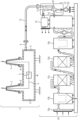
- the figure shows an example of an electrical energy transmission device 1.
- the electrical energy transmission device 1 is designed as a fluid-insulated circuit breaker.
- the circuit breaker has a so-called dead tank design.
- any other designs of electrical energy transmission devices 1 that have a fluid receiving space are also conceivable.
- circuit breakers in a life tank design or so-called gas-insulated switchgear can serve as electrical energy transmission devices 1.
- electrical energy transmission devices 1 with active components (switchable components) in the fluid receiving space electrical energy transmission devices 1 can also have only passive components in the fluid receiving space. No switching processes occur in passive components.
- the electrical energy transmission device 1 has an encapsulation housing 2.
- the encapsulation housing 2 is essentially designed as a hollow cylindrical body with an essentially circular cross-section.
- the hollow cylindrical hollow body is sealed fluid-tight at the front.
- the encapsulation housing 2 defines a fluid receiving space 3 in its interior.
- a phase conductor 4 is arranged in the fluid receiving space 3.
- the phase conductor 4 is equipped with a switching device 5 (active assembly).
- the phase conductor 4 is mounted centrally in the encapsulation housing 2 and extends on both sides of the switching device 5 and within the switching device 5.
- casing-side nozzles 6 are arranged on the encapsulation housing 2.
- So-called outdoor bushings 7 are arranged on the casing-side nozzles 6.
- the outdoor bushings 7 serve to allow the phase conductor 4 to pass in an electrically insulated manner through a wall of the encapsulating housing 2 into the vicinity of the electrical energy transmission device 1.
- the phase conductor 4 thus runs from the vicinity of the electrical energy transmission device 1 into the encapsulating housing 2, passes through the switching device 5 there and leaves the encapsulating housing 2 again into the vicinity of the electrical energy transmission device 1.
- the hollow cylindrical base body of the encapsulation housing 2 is made of an electrically conductive material.
- the electrically conductive sections of the encapsulation housing 2 are subjected to ground potential.
- the encapsulation housing 2 or the fluid receiving space 3 form a fluid-tight barrier so that a fluid cannot escape from the fluid receiving space 3.
- the encapsulation housing 2 has a filling valve 8.
- the filling valve 8 By means of the filling valve 8 it is possible to fill the fluid receiving space 3 with an electrically insulating fluid or to remove an electrically insulating fluid from the fluid receiving space 3.
- the filling valve 8 has a valve by means of which the filling valve 8 can be opened. and can be closed.
- a maintenance unit 9 is provided for filling or emptying the fluid receiving space 3 of the electrical energy transmission device 1.
- the maintenance unit 9 is designed to be mobile, so that the maintenance unit 9 can be installed, for example, in a container or on a container platform.
- the maintenance unit 9 has several filter arrangements 10a, 10b, 10c, 10d, 10e.
- Each of the filter arrangements 10a, 10b, 10c, 10d, 10e serves to treat air taken from the environment of the electrical energy transmission device 1.
- the filter arrangements 10a, 10b, 10c, 10d, 10e are constructed in a cascading manner, so that the more filter arrangements 10a, 10b, 10c, 10d, 10e are passed through, the more clean the atmospheric air taken from the environment of the electrical energy transmission device is.
- the filter arrangements 10a, 10b, 10c, 10d, 10e can also be referred to as zero air generators.
- the first filter arrangement 10a is designed as an air inlet, with a large-area air inlet opening provided with a grid-like barrier to prevent large foreign bodies from entering the maintenance unit 9.
- the first filter arrangement 10a is followed by a second filter arrangement 10b, in which particles and aerosols are removed from the inflowing air volume. For example, moisture can also be separated in the first filter arrangement, so that the inflowing air is dried.
- a third filter arrangement 10c it is now possible to remove hydrocarbons from the incoming air by oxidation. To promote the oxidation, the incoming air can be tempered.
- a catalyst can be used to convert gaseous hydrocarbons, for example into carbon dioxide CO 2 and water H 2 O, and then remove them from the third filter arrangement 10c.
- a fourth filter arrangement 10d it is now possible to further bind residual organic compounds, such as hydrocarbons, by further treating the atmospheric air taken from the environment using an adsorption filter.
- a mechanical cleaning of remaining foreign particles can now be carried out in a fine dust filter.
- a passage of air through the filter arrangements 101, 10b, 10c, 10d, 10e can be conveyed by a blower.
- a passage through the various filter arrangements 10a, 10b, 10c, 10d, 10e, treated, in particular purified, atmospheric air taken from the environment is now available.
- the compressor 11 takes on the function of a blower to convey an air flow through the filter systems 10a, 10b, 10c, 10d, 10e.
- the intermediate storage 12 for example, fluctuations during the treatment of the atmospheric air in the filter arrangements 10a, 10b, 10c, 10d, 10e can be compensated.
- a valve assembly 13 is connected to the outlet of the intermediate storage 12. Via various valves of the valve assembly 13, it is possible to allow treated atmospheric air temporarily stored in the intermediate storage 12 to flow into the fluid receiving space 3 of the electrical energy transmission device.
- the valve assembly 13 has an outlet valve 14 for this purpose. On the outlet side, the outlet valve 14 is provided with a coupling point in order to establish a connection to the filling fitting 8 of the electrical energy transmission device 1 via a removable piping 15.
- the outlet valve 14 of the valve assembly 13 is in turn connected to an intermediate storage outlet valve 16.
- the intermediate storage outlet valve 16 makes it possible to close the intermediate storage 12 so that a compressed treated air volume can be enclosed within the intermediate storage 12. By opening the intermediate storage outlet valve 16 and the outlet valve 14 of the valve assembly 13, it is possible to allow a compressed fluid to pass from the intermediate storage 12 into the fluid receiving space 3.
- a suction branch line 17 and a discharge branch line 18 are arranged in the piping between the intermediate storage outlet valve 16 and the outlet valve 14 of the valve assembly 13. Both the suction branch line 17 and the discharge branch line 18 can be closed using a valve.
- the discharge branch line 18 opens into a catalyst 19 through which a fluid that is to be discharged from the valve assembly 13 can be released into the environment.
- the catalyst 19 ensures catalysis of foreign substances that should not be discharged into the environment of the electrical energy transmission device.
- the catalyst 11 can be used in particular to convert nitrogen oxides.
- the fluid receiving chamber 3 of the electrical energy transmission device 1 is filled with an undefined gas.
- the filling valve 8 is opened.
- the intermediate storage outlet valve 16 is closed.
- the valve in the drain branch line 18 is also closed.
- the valve in the suction branch line 17 is open.
- the outlet valve 14 of the valve assembly 13 is also open. This makes it possible to place the fluid receiving chamber 3 under negative pressure using a vacuum pump 20 located in the suction branch line 17. A vacuum is generated in the fluid receiving chamber 3. While the fluid receiving chamber 3 is being vacuumed, air taken in from the environment of the electrical energy transmission device is cleaned in parallel.
- the volume of purified air taken from the intermediate storage 12 can be compensated for by means of the compressor 11. Air continues to be sucked in via the filter arrangement 10a, 10b, 10c, 10d and treated air continues to be introduced into the interior of the fluid receiving chamber 3. Once a sufficient density (specific pressure at a specific temperature) has been reached in the fluid receiving chamber 3, the filling valve 8 of the encapsulation housing 2 can be closed. The intermediate storage outlet valve 16 can also be closed. If necessary, the compressor 11 can then be switched off, since further treated fluid is not required for the fluid receiving chamber 3 of the electrical energy transmission device 1. If further fluid receiving chambers 3 of this or another electrical energy transmission device 1 still need to be filled, compressed and purified air can also be generated in the meantime and temporarily stored in the intermediate storage 12. It is now possible to remove the piping between the outlet valve 14, the valve assembly 13 and the filling fitting 8.
- the filling valve 8 and the outlet valve 14 are connected to one another via a pipe 15.
- the intermediate storage outlet valve 16 is closed.
- the valve in the suction branch line 17 is also closed. It is now possible to open the valve in the discharge branch line 18.
- the filling valve 8 and the outlet valve 14 are opened.
- a catalysis causes a conversion of foreign substances and the fluid which was previously taken from the environment of the electrical energy transmission device 1 is returned to the environment of the electrical energy transmission device 1.
- a pump can also be arranged in the drain branch line 18.
- the suction branch line 17 can also be used to drain a fluid located in the fluid receiving chamber 3 (if necessary with a catalyst/filter). A negative pressure inside the fluid receiving chamber 3 can ensure that the atmospheric air previously taken from the environment is almost completely returned to the environment.
Landscapes
- Engineering & Computer Science (AREA)
- Power Engineering (AREA)
- Mechanical Engineering (AREA)
- General Engineering & Computer Science (AREA)
- Manufacturing & Machinery (AREA)
- Physical Or Chemical Processes And Apparatus (AREA)
- Electrostatic Separation (AREA)
- Computer Networks & Wireless Communication (AREA)
Claims (5)
- Gestion du cycle de vie d'un fluide isolant électriquement, qui, pour une isolation électrique, est disposé dans un espace (3) de réception de fluide d'un dispositif (1) de transport d'énergie électrique, dans lequel- on prélève, de l'atmosphère ambiante du dispositif de transport d'énergie électrique, de l'air atmosphérique, on traite l'air prélevé, en particulier en l'épurant, et on l'introduit dans l'espace (3) de réception d'un fluide,- avant de mettre le fluide prélevé dans l'espace (3) de réception d'un fluide, on y fait le vide,- au moyen d'un compresseur (11), on aspire, de l'atmosphère ambiante, de l'air en passant par des dispositifs (10a, 10b, 10c, 10d, 10e) de filtration, puis on pompe l'air atmosphérique traité, prélevé de l'atmosphère ambiante, dans un accumulateur (12) intermédiaire et on l'y soumet à une surpression, de manière à effectuer, pendant la mise sous vide de l'espace (3) de réception d'un fluide, en parallèle, une épuration de l'air prélevé de l'atmosphère ambiante du dispositif de transport d'énergie électrique.
- Gestion du cycle de vie d'un fluide isolant électriquement suivant la revendication 1,
caractérisée en ce que
l'on soumet le fluide à une surpression. - Gestion du cycle de vie d'un fluide isolant électriquement suivant l'une des revendications 1 ou 2,
caractérisée en ce que
la capacité de l'accumulateur (12) intermédiaire est plus petite que la capacité de réception de l'espace (3) de réception d'un fluide. - Gestion du cycle de vie d'un fluide isolant électriquement suivant l'une des revendications 1 à 3,
caractérisée en ce que
l'on évacue dans l'atmosphère ambiante le fluide se trouvant dans l'espace (3) de réception d'un fluide. - Gestion du cycle de vie d'un fluide isolant électriquement suivant la revendication 4,
caractérisée en ce que,
avant de céder le fluide à l'atmosphère ambiante, on traite le fluide, en particulier en l'épurant.
Applications Claiming Priority (2)
| Application Number | Priority Date | Filing Date | Title |
|---|---|---|---|
| DE102016215598.9A DE102016215598A1 (de) | 2016-08-19 | 2016-08-19 | Elektroenergieübertragungseinrichtung sowie Lebenszyklusmanagement |
| PCT/EP2017/068177 WO2018033332A1 (fr) | 2016-08-19 | 2017-07-19 | Dispositif de transmission d'énergie électrique et gestion de cycle de vie |
Publications (3)
| Publication Number | Publication Date |
|---|---|
| EP3476016A1 EP3476016A1 (fr) | 2019-05-01 |
| EP3476016C0 EP3476016C0 (fr) | 2024-05-29 |
| EP3476016B1 true EP3476016B1 (fr) | 2024-05-29 |
Family
ID=59399413
Family Applications (1)
| Application Number | Title | Priority Date | Filing Date |
|---|---|---|---|
| EP17743308.3A Active EP3476016B1 (fr) | 2016-08-19 | 2017-07-19 | Gestion du cycle de vie d'un fluide isolant électrique |
Country Status (5)
| Country | Link |
|---|---|
| US (1) | US11509121B2 (fr) |
| EP (1) | EP3476016B1 (fr) |
| CN (1) | CN109565158B (fr) |
| DE (1) | DE102016215598A1 (fr) |
| WO (1) | WO2018033332A1 (fr) |
Families Citing this family (1)
| Publication number | Priority date | Publication date | Assignee | Title |
|---|---|---|---|---|
| CN117941014A (zh) * | 2022-08-09 | 2024-04-26 | 日立能源有限公司 | 用于产生、传输和/或分配电能的电气设备 |
Citations (1)
| Publication number | Priority date | Publication date | Assignee | Title |
|---|---|---|---|---|
| DE2702763A1 (de) * | 1977-01-24 | 1978-07-27 | Bbc Brown Boveri & Cie | Drucklufterzeugungsanlage fuer elektrische schaltanlagen |
Family Cites Families (27)
| Publication number | Priority date | Publication date | Assignee | Title |
|---|---|---|---|---|
| FR1593617A (fr) * | 1968-11-06 | 1970-06-01 | ||
| FR2082144A5 (fr) * | 1970-03-04 | 1971-12-10 | Merlin Gerin | |
| DE2633355C3 (de) * | 1976-07-24 | 1981-01-29 | Calor-Emag Elektrizitaets-Aktiengesellschaft, 4030 Ratingen | Verfahren zum Füllen gekapselter Hochspannungsanlagen mit einem Isoliergas |
| DE2702767C2 (de) * | 1977-01-24 | 1982-09-09 | Brown, Boveri & Cie Ag, 6800 Mannheim | Verfahren zum Trocknen von Druckluft für elektrische Schaltzwecke und Trockenvorrichtung zur Durchführung des Verfahrens |
| DE3122886C2 (de) * | 1981-06-10 | 1986-03-20 | Calor-Emag Elektrizitäts-Aktiengesellschaft, 4030 Ratingen | Verfahren zum Füllen und Entleeren von Gehäusen für gasisolierte elektrische Geräte und Anlagen |
| JP3356965B2 (ja) * | 1997-06-20 | 2002-12-16 | 株式会社日立製作所 | Sf6ガス回収・精製処理装置及び方法 |
| JP4072236B2 (ja) * | 1998-03-25 | 2008-04-09 | 株式会社日立製作所 | ガス絶縁開閉装置 |
| JP4357046B2 (ja) * | 1999-10-01 | 2009-11-04 | 株式会社東芝 | ガス回収装置 |
| JP2001194409A (ja) * | 2000-01-12 | 2001-07-19 | Toshiba Corp | ガス絶縁機器の耐電圧試験装置および方法 |
| US7030335B2 (en) * | 2000-03-17 | 2006-04-18 | Applied Materials, Inc. | Plasma reactor with overhead RF electrode tuned to the plasma with arcing suppression |
| US6797336B2 (en) * | 2001-03-22 | 2004-09-28 | Ambp Tech Corporation | Multi-component substances and processes for preparation thereof |
| DE10302857B3 (de) | 2003-01-22 | 2004-04-22 | Siemens Ag | Verfahren sowie Vorrichtung zur Überwachung eines Isoliergases |
| JP2006180588A (ja) * | 2004-12-21 | 2006-07-06 | Sumitomo Electric Ind Ltd | 超電導機器の電力引き出し構造 |
| US7439630B2 (en) * | 2006-09-08 | 2008-10-21 | Helius Inc. | System and methodology for generating electricity using a chemical heat engine and piezoelectric material |
| DE112009002045T5 (de) * | 2009-06-12 | 2011-07-28 | Abb Technology Ag | Dielektrisches Isolationsmedium |
| CN102484360B (zh) * | 2009-10-29 | 2014-08-27 | 三菱电机株式会社 | 电气开关装置 |
| DK2652752T3 (en) * | 2010-12-14 | 2016-01-11 | Abb Technology Ag | Dielectric INSULATION MEDIUM |
| EP2805394B1 (fr) * | 2012-01-19 | 2016-09-14 | Hydro-Québec | Dispositif pour un appareil de commutation extérieur |
| DE102012209307A1 (de) * | 2012-06-01 | 2013-12-05 | Siemens Aktiengesellschaft | Druckgasisolierte Elektroenergieübertragungseinrichtung |
| US9481351B2 (en) * | 2012-07-02 | 2016-11-01 | Ford Global Technologies, Llc | Hybrid vehicle and associated engine start and stop control method |
| KR101315995B1 (ko) * | 2013-05-06 | 2013-10-10 | 샤론일렉콤 주식회사 | 활선 상태에서의 지상기기 절연가스 관리 장치 및 그 방법 |
| CN204290123U (zh) * | 2014-09-10 | 2015-04-22 | 国家电网公司 | 新型三柱式绝缘装置 |
| DE102015201678A1 (de) * | 2015-01-30 | 2016-08-04 | Siemens Aktiengesellschaft | Elektroenergieübertragungseinrichtung |
| DE102015108748A1 (de) | 2015-06-02 | 2016-12-08 | Dilo Armaturen Und Anlagen Gmbh | Servicegerät |
| DE102017217240A1 (de) * | 2017-09-27 | 2019-03-28 | Siemens Aktiengesellschaft | Anordnung mit einer gasisolierten Schaltanlage |
| DE102017220569A1 (de) * | 2017-11-17 | 2019-05-23 | Siemens Aktiengesellschaft | Verfahren zum Befüllen eines Behälters sowie Servicegerät zum Durchführen des Verfahrens |
| DE102018212581A1 (de) * | 2018-07-27 | 2020-01-30 | Siemens Aktiengesellschaft | Elektrisches Schaltgerät |
-
2016
- 2016-08-19 DE DE102016215598.9A patent/DE102016215598A1/de not_active Withdrawn
-
2017
- 2017-07-19 CN CN201780050469.8A patent/CN109565158B/zh active Active
- 2017-07-19 WO PCT/EP2017/068177 patent/WO2018033332A1/fr not_active Ceased
- 2017-07-19 US US16/326,424 patent/US11509121B2/en active Active
- 2017-07-19 EP EP17743308.3A patent/EP3476016B1/fr active Active
Patent Citations (1)
| Publication number | Priority date | Publication date | Assignee | Title |
|---|---|---|---|---|
| DE2702763A1 (de) * | 1977-01-24 | 1978-07-27 | Bbc Brown Boveri & Cie | Drucklufterzeugungsanlage fuer elektrische schaltanlagen |
Also Published As
| Publication number | Publication date |
|---|---|
| CN109565158B (zh) | 2021-09-03 |
| US11509121B2 (en) | 2022-11-22 |
| US20210336479A1 (en) | 2021-10-28 |
| DE102016215598A1 (de) | 2018-02-22 |
| EP3476016C0 (fr) | 2024-05-29 |
| EP3476016A1 (fr) | 2019-05-01 |
| WO2018033332A1 (fr) | 2018-02-22 |
| CN109565158A (zh) | 2019-04-02 |
Similar Documents
| Publication | Publication Date | Title |
|---|---|---|
| DE1002842B (de) | Druckgas-Stromunterbrecher | |
| DE202009018214U1 (de) | Gekapselte Schaltanlage | |
| BG62860B1 (bg) | Метод и устройство за филтруване, дегазиране, дехидратиранеи отстраняване на продуктите на стареене в нефтени масла | |
| EP3476016B1 (fr) | Gestion du cycle de vie d'un fluide isolant électrique | |
| EP3799663B1 (fr) | Appareil de commutation électrique | |
| US7938895B2 (en) | Gas-insulated switchgear apparatus and gas filter device | |
| EP3685481B1 (fr) | Méthode de remplissage d'une cuve et dispositif pour éxécuter la méthode | |
| DE10252652B4 (de) | Vorrichtung und Verfahren zur Entgasung von Fluidproben | |
| EP3283833B1 (fr) | Procédé de séchage d'un compartiment à gaz ainsi qu'ensemble comprenant un compartiment à gaz rempli d'un gaz protecteur | |
| DE69712387T2 (de) | Abgasanlage in einem Ionenimplantierungssystem | |
| EP3207607B1 (fr) | Installation électrique comprenant un gaz électriquement isolant et un capteur de radicaux libres | |
| DE102016200453A1 (de) | Elektrische Isolationsanordnung sowie Verfahren zur Wartung einer elektrischen Isolationsanordnung | |
| WO2015110216A1 (fr) | Procédé de renforcement du vide dans un réservoir de stockage isolé par une enveloppe sous vide d'un véhicule ainsi que station de mise sous vide | |
| WO2017012775A1 (fr) | Installation de haute et moyenne tension pourvue d'une chambre isolante et d'un absorbeur à membrane sélective | |
| DE102015213597A1 (de) | Hoch- oder Mittelspannungsanordnung mit Isolierraum und Absorptionsmittel | |
| DE10052550A1 (de) | Verfahren zur Aufrechterhaltung und Verbesserung der elektrischen Festigkeit von in ölgefüllten Hochspannungsgeräten sich befindendem Isolieröl und Öl-/Papierisolierungen während des Dauerbetriebes mit Betriebsspannung und Einrichtung zur Isolierölaufbereitung | |
| DE60319827T2 (de) | System und Verfahren zur Wiederverwendung von Gasen und gasisolierte elektrische Vorrichtung | |
| DE2459998A1 (de) | Vorrichtung zum reinigen des gasfoermigen isoliermittels von sf tief 6 -isolierten hochspannungsschaltanlagen und -geraeten | |
| DE6602887U (de) | Einrichtung fuer druckgasschalter mit sf6 als loeschmittel und mit geschlossenem gaskreislauf. | |
| DE69919839T2 (de) | Abtrenngerät für Nuklearabfall | |
| DE2633355A1 (de) | Verfahren zum fuellen gekapselter hochspannungsanlagen mit einem isoliergas | |
| DD247110A1 (de) | Druckgasisolierung fuer metallgekapselte hochspannungsgeraete | |
| DE2059770B2 (de) | Einrichtung zum Abführen von Gasen | |
| DE2632971A1 (de) | Durchfuehrungsisolator | |
| DE1464612B2 (de) | Vorrichtung zum Pumpen organischer Gase aus einem teilweise evakuierten Raum |
Legal Events
| Date | Code | Title | Description |
|---|---|---|---|
| STAA | Information on the status of an ep patent application or granted ep patent |
Free format text: STATUS: UNKNOWN |
|
| STAA | Information on the status of an ep patent application or granted ep patent |
Free format text: STATUS: THE INTERNATIONAL PUBLICATION HAS BEEN MADE |
|
| PUAI | Public reference made under article 153(3) epc to a published international application that has entered the european phase |
Free format text: ORIGINAL CODE: 0009012 |
|
| STAA | Information on the status of an ep patent application or granted ep patent |
Free format text: STATUS: REQUEST FOR EXAMINATION WAS MADE |
|
| 17P | Request for examination filed |
Effective date: 20190122 |
|
| AK | Designated contracting states |
Kind code of ref document: A1 Designated state(s): AL AT BE BG CH CY CZ DE DK EE ES FI FR GB GR HR HU IE IS IT LI LT LU LV MC MK MT NL NO PL PT RO RS SE SI SK SM TR |
|
| AX | Request for extension of the european patent |
Extension state: BA ME |
|
| DAV | Request for validation of the european patent (deleted) | ||
| DAX | Request for extension of the european patent (deleted) | ||
| STAA | Information on the status of an ep patent application or granted ep patent |
Free format text: STATUS: EXAMINATION IS IN PROGRESS |
|
| 17Q | First examination report despatched |
Effective date: 20200824 |
|
| RAP1 | Party data changed (applicant data changed or rights of an application transferred) |
Owner name: SIEMENS ENERGY GLOBAL GMBH & CO. KG |
|
| GRAP | Despatch of communication of intention to grant a patent |
Free format text: ORIGINAL CODE: EPIDOSNIGR1 |
|
| STAA | Information on the status of an ep patent application or granted ep patent |
Free format text: STATUS: GRANT OF PATENT IS INTENDED |
|
| RIC1 | Information provided on ipc code assigned before grant |
Ipc: H01H 33/57 20060101ALN20231214BHEP Ipc: H02B 13/055 20060101ALI20231214BHEP Ipc: H02B 3/00 20060101AFI20231214BHEP |
|
| INTG | Intention to grant announced |
Effective date: 20240105 |
|
| RIC1 | Information provided on ipc code assigned before grant |
Ipc: H01H 33/57 20060101ALN20231218BHEP Ipc: H02B 13/055 20060101ALI20231218BHEP Ipc: H02B 3/00 20060101AFI20231218BHEP |
|
| GRAS | Grant fee paid |
Free format text: ORIGINAL CODE: EPIDOSNIGR3 |
|
| GRAA | (expected) grant |
Free format text: ORIGINAL CODE: 0009210 |
|
| STAA | Information on the status of an ep patent application or granted ep patent |
Free format text: STATUS: THE PATENT HAS BEEN GRANTED |
|
| AK | Designated contracting states |
Kind code of ref document: B1 Designated state(s): AL AT BE BG CH CY CZ DE DK EE ES FI FR GB GR HR HU IE IS IT LI LT LU LV MC MK MT NL NO PL PT RO RS SE SI SK SM TR |
|
| REG | Reference to a national code |
Ref country code: CH Ref legal event code: EP |
|
| REG | Reference to a national code |
Ref country code: IE Ref legal event code: FG4D Free format text: LANGUAGE OF EP DOCUMENT: GERMAN |
|
| REG | Reference to a national code |
Ref country code: DE Ref legal event code: R096 Ref document number: 502017016144 Country of ref document: DE |
|
| U01 | Request for unitary effect filed |
Effective date: 20240529 |
|
| U07 | Unitary effect registered |
Designated state(s): AT BE BG DE DK EE FI FR IT LT LU LV MT NL PT SE SI Effective date: 20240604 |
|
| U20 | Renewal fee for the european patent with unitary effect paid |
Year of fee payment: 8 Effective date: 20240725 |
|
| PG25 | Lapsed in a contracting state [announced via postgrant information from national office to epo] |
Ref country code: IS Free format text: LAPSE BECAUSE OF FAILURE TO SUBMIT A TRANSLATION OF THE DESCRIPTION OR TO PAY THE FEE WITHIN THE PRESCRIBED TIME-LIMIT Effective date: 20240929 |
|
| PG25 | Lapsed in a contracting state [announced via postgrant information from national office to epo] |
Ref country code: HR Free format text: LAPSE BECAUSE OF FAILURE TO SUBMIT A TRANSLATION OF THE DESCRIPTION OR TO PAY THE FEE WITHIN THE PRESCRIBED TIME-LIMIT Effective date: 20240529 |
|
| PG25 | Lapsed in a contracting state [announced via postgrant information from national office to epo] |
Ref country code: GR Free format text: LAPSE BECAUSE OF FAILURE TO SUBMIT A TRANSLATION OF THE DESCRIPTION OR TO PAY THE FEE WITHIN THE PRESCRIBED TIME-LIMIT Effective date: 20240830 |
|
| PG25 | Lapsed in a contracting state [announced via postgrant information from national office to epo] |
Ref country code: ES Free format text: LAPSE BECAUSE OF FAILURE TO SUBMIT A TRANSLATION OF THE DESCRIPTION OR TO PAY THE FEE WITHIN THE PRESCRIBED TIME-LIMIT Effective date: 20240529 |
|
| PG25 | Lapsed in a contracting state [announced via postgrant information from national office to epo] |
Ref country code: PL Free format text: LAPSE BECAUSE OF FAILURE TO SUBMIT A TRANSLATION OF THE DESCRIPTION OR TO PAY THE FEE WITHIN THE PRESCRIBED TIME-LIMIT Effective date: 20240529 |
|
| PG25 | Lapsed in a contracting state [announced via postgrant information from national office to epo] |
Ref country code: PL Free format text: LAPSE BECAUSE OF FAILURE TO SUBMIT A TRANSLATION OF THE DESCRIPTION OR TO PAY THE FEE WITHIN THE PRESCRIBED TIME-LIMIT Effective date: 20240529 Ref country code: IS Free format text: LAPSE BECAUSE OF FAILURE TO SUBMIT A TRANSLATION OF THE DESCRIPTION OR TO PAY THE FEE WITHIN THE PRESCRIBED TIME-LIMIT Effective date: 20240929 Ref country code: HR Free format text: LAPSE BECAUSE OF FAILURE TO SUBMIT A TRANSLATION OF THE DESCRIPTION OR TO PAY THE FEE WITHIN THE PRESCRIBED TIME-LIMIT Effective date: 20240529 Ref country code: GR Free format text: LAPSE BECAUSE OF FAILURE TO SUBMIT A TRANSLATION OF THE DESCRIPTION OR TO PAY THE FEE WITHIN THE PRESCRIBED TIME-LIMIT Effective date: 20240830 Ref country code: ES Free format text: LAPSE BECAUSE OF FAILURE TO SUBMIT A TRANSLATION OF THE DESCRIPTION OR TO PAY THE FEE WITHIN THE PRESCRIBED TIME-LIMIT Effective date: 20240529 Ref country code: RS Free format text: LAPSE BECAUSE OF FAILURE TO SUBMIT A TRANSLATION OF THE DESCRIPTION OR TO PAY THE FEE WITHIN THE PRESCRIBED TIME-LIMIT Effective date: 20240829 |
|
| PG25 | Lapsed in a contracting state [announced via postgrant information from national office to epo] |
Ref country code: CZ Free format text: LAPSE BECAUSE OF FAILURE TO SUBMIT A TRANSLATION OF THE DESCRIPTION OR TO PAY THE FEE WITHIN THE PRESCRIBED TIME-LIMIT Effective date: 20240529 |
|
| PG25 | Lapsed in a contracting state [announced via postgrant information from national office to epo] |
Ref country code: SK Free format text: LAPSE BECAUSE OF FAILURE TO SUBMIT A TRANSLATION OF THE DESCRIPTION OR TO PAY THE FEE WITHIN THE PRESCRIBED TIME-LIMIT Effective date: 20240529 Ref country code: RO Free format text: LAPSE BECAUSE OF FAILURE TO SUBMIT A TRANSLATION OF THE DESCRIPTION OR TO PAY THE FEE WITHIN THE PRESCRIBED TIME-LIMIT Effective date: 20240529 |
|
| PG25 | Lapsed in a contracting state [announced via postgrant information from national office to epo] |
Ref country code: SM Free format text: LAPSE BECAUSE OF FAILURE TO SUBMIT A TRANSLATION OF THE DESCRIPTION OR TO PAY THE FEE WITHIN THE PRESCRIBED TIME-LIMIT Effective date: 20240529 |
|
| PG25 | Lapsed in a contracting state [announced via postgrant information from national office to epo] |
Ref country code: SM Free format text: LAPSE BECAUSE OF FAILURE TO SUBMIT A TRANSLATION OF THE DESCRIPTION OR TO PAY THE FEE WITHIN THE PRESCRIBED TIME-LIMIT Effective date: 20240529 Ref country code: SK Free format text: LAPSE BECAUSE OF FAILURE TO SUBMIT A TRANSLATION OF THE DESCRIPTION OR TO PAY THE FEE WITHIN THE PRESCRIBED TIME-LIMIT Effective date: 20240529 Ref country code: RO Free format text: LAPSE BECAUSE OF FAILURE TO SUBMIT A TRANSLATION OF THE DESCRIPTION OR TO PAY THE FEE WITHIN THE PRESCRIBED TIME-LIMIT Effective date: 20240529 Ref country code: CZ Free format text: LAPSE BECAUSE OF FAILURE TO SUBMIT A TRANSLATION OF THE DESCRIPTION OR TO PAY THE FEE WITHIN THE PRESCRIBED TIME-LIMIT Effective date: 20240529 |
|
| PG25 | Lapsed in a contracting state [announced via postgrant information from national office to epo] |
Ref country code: MC Free format text: LAPSE BECAUSE OF FAILURE TO SUBMIT A TRANSLATION OF THE DESCRIPTION OR TO PAY THE FEE WITHIN THE PRESCRIBED TIME-LIMIT Effective date: 20240529 |
|
| PLBE | No opposition filed within time limit |
Free format text: ORIGINAL CODE: 0009261 |
|
| STAA | Information on the status of an ep patent application or granted ep patent |
Free format text: STATUS: NO OPPOSITION FILED WITHIN TIME LIMIT |
|
| 26N | No opposition filed |
Effective date: 20250303 |
|
| PG25 | Lapsed in a contracting state [announced via postgrant information from national office to epo] |
Ref country code: IE Free format text: LAPSE BECAUSE OF NON-PAYMENT OF DUE FEES Effective date: 20240719 |
|
| U20 | Renewal fee for the european patent with unitary effect paid |
Year of fee payment: 9 Effective date: 20250725 |
|
| PGFP | Annual fee paid to national office [announced via postgrant information from national office to epo] |
Ref country code: NO Payment date: 20250718 Year of fee payment: 9 |
|
| PGFP | Annual fee paid to national office [announced via postgrant information from national office to epo] |
Ref country code: GB Payment date: 20250722 Year of fee payment: 9 |
|
| PGFP | Annual fee paid to national office [announced via postgrant information from national office to epo] |
Ref country code: CH Payment date: 20250801 Year of fee payment: 9 |
|
| PG25 | Lapsed in a contracting state [announced via postgrant information from national office to epo] |
Ref country code: CY Free format text: LAPSE BECAUSE OF FAILURE TO SUBMIT A TRANSLATION OF THE DESCRIPTION OR TO PAY THE FEE WITHIN THE PRESCRIBED TIME-LIMIT; INVALID AB INITIO Effective date: 20170719 |
|
| PG25 | Lapsed in a contracting state [announced via postgrant information from national office to epo] |
Ref country code: HU Free format text: LAPSE BECAUSE OF FAILURE TO SUBMIT A TRANSLATION OF THE DESCRIPTION OR TO PAY THE FEE WITHIN THE PRESCRIBED TIME-LIMIT; INVALID AB INITIO Effective date: 20170719 |