EP3476262B1 - Robot ménager - Google Patents
Robot ménager Download PDFInfo
- Publication number
- EP3476262B1 EP3476262B1 EP16919995.7A EP16919995A EP3476262B1 EP 3476262 B1 EP3476262 B1 EP 3476262B1 EP 16919995 A EP16919995 A EP 16919995A EP 3476262 B1 EP3476262 B1 EP 3476262B1
- Authority
- EP
- European Patent Office
- Prior art keywords
- cup body
- cutter head
- blades
- cutter
- central axis
- Prior art date
- Legal status (The legal status is an assumption and is not a legal conclusion. Google has not performed a legal analysis and makes no representation as to the accuracy of the status listed.)
- Active
Links
Images




Classifications
-
- A—HUMAN NECESSITIES
- A47—FURNITURE; DOMESTIC ARTICLES OR APPLIANCES; COFFEE MILLS; SPICE MILLS; SUCTION CLEANERS IN GENERAL
- A47J—KITCHEN EQUIPMENT; COFFEE MILLS; SPICE MILLS; APPARATUS FOR MAKING BEVERAGES
- A47J43/00—Implements for preparing or holding food, not provided for in other groups of this subclass
- A47J43/04—Machines for domestic use not covered elsewhere, e.g. for grinding, mixing, stirring, kneading, emulsifying, whipping or beating foodstuffs, e.g. power-driven
- A47J43/046—Machines for domestic use not covered elsewhere, e.g. for grinding, mixing, stirring, kneading, emulsifying, whipping or beating foodstuffs, e.g. power-driven with tools driven from the bottom side
-
- A—HUMAN NECESSITIES
- A47—FURNITURE; DOMESTIC ARTICLES OR APPLIANCES; COFFEE MILLS; SPICE MILLS; SUCTION CLEANERS IN GENERAL
- A47J—KITCHEN EQUIPMENT; COFFEE MILLS; SPICE MILLS; APPARATUS FOR MAKING BEVERAGES
- A47J43/00—Implements for preparing or holding food, not provided for in other groups of this subclass
- A47J43/04—Machines for domestic use not covered elsewhere, e.g. for grinding, mixing, stirring, kneading, emulsifying, whipping or beating foodstuffs, e.g. power-driven
- A47J43/07—Parts or details, e.g. mixing tools, whipping tools
- A47J43/0716—Parts or details, e.g. mixing tools, whipping tools for machines with tools driven from the lower side
- A47J43/0722—Mixing, whipping or cutting tools
-
- A—HUMAN NECESSITIES
- A47—FURNITURE; DOMESTIC ARTICLES OR APPLIANCES; COFFEE MILLS; SPICE MILLS; SUCTION CLEANERS IN GENERAL
- A47J—KITCHEN EQUIPMENT; COFFEE MILLS; SPICE MILLS; APPARATUS FOR MAKING BEVERAGES
- A47J36/00—Parts, details or accessories of cooking-vessels
- A47J36/06—Lids or covers for cooking-vessels
- A47J36/10—Lid-locking devices
-
- A—HUMAN NECESSITIES
- A47—FURNITURE; DOMESTIC ARTICLES OR APPLIANCES; COFFEE MILLS; SPICE MILLS; SUCTION CLEANERS IN GENERAL
- A47J—KITCHEN EQUIPMENT; COFFEE MILLS; SPICE MILLS; APPARATUS FOR MAKING BEVERAGES
- A47J43/00—Implements for preparing or holding food, not provided for in other groups of this subclass
- A47J43/04—Machines for domestic use not covered elsewhere, e.g. for grinding, mixing, stirring, kneading, emulsifying, whipping or beating foodstuffs, e.g. power-driven
- A47J43/07—Parts or details, e.g. mixing tools, whipping tools
- A47J43/0727—Mixing bowls
-
- A—HUMAN NECESSITIES
- A47—FURNITURE; DOMESTIC ARTICLES OR APPLIANCES; COFFEE MILLS; SPICE MILLS; SUCTION CLEANERS IN GENERAL
- A47J—KITCHEN EQUIPMENT; COFFEE MILLS; SPICE MILLS; APPARATUS FOR MAKING BEVERAGES
- A47J43/00—Implements for preparing or holding food, not provided for in other groups of this subclass
- A47J43/04—Machines for domestic use not covered elsewhere, e.g. for grinding, mixing, stirring, kneading, emulsifying, whipping or beating foodstuffs, e.g. power-driven
- A47J43/07—Parts or details, e.g. mixing tools, whipping tools
- A47J43/08—Driving mechanisms
- A47J43/085—Driving mechanisms for machines with tools driven from the lower side
Definitions
- the present disclosure relates to the field of household electric apparatuses, and specifically relates to a food processor.
- the existing stirring system is often regular in shape, the central axes of a cutter head, a cutter and a cup body are collinear, while the contours of the cutter head and the cup body are also regular in shape, so the turbulent effect and the stirring performance are poor.
- EP2486833A2 relates to a mixing vessel, that is used with a motorized food processor, having a vessel wall with an cylindrical upper section and a frustoconical lower section.
- the upper section has a longitudinal axis generally centered within the upper section and an upper opening defining an upper end of the vessel wall.
- the lower section is tapered towards a lower circular opening defining a lower end of the vessel wall and has a plurality of contiguous cambered protuberances forming a hypocycloidal inner surface within the lower section.
- a base removably closes the lower circular opening and has an upwardly tapered structure and a vertical rotational spindle.
- a blade assembly is located at on the spindle.
- the blade assembly has a pair of upwardly extending blade arms, a pair of radially extending blade arms and a pair of downwardly extending blade arms.
- EP2572614A1 relates to a blender including a container having a plurality of substantially triangular shaped ribs projecting into a processing zone of the container.
- the plurality of spaced ribs each include a width and a depth that taper from a top end section adjacent a teardrop shaped opening of the container to a more narrow bottom end section adjacent a bottom wall of the container.
- a side wall of the container continuously tapers from the teardrop shaped opening to a substantially square shaped bottom end portion including first, second, third and fourth side wall sections connected to one another at respective rounded corners.
- a blade assembly is coupled to the container and includes a plurality of blades angled at different planes with respect to a horizontal plane. Each of the blades includes a beveled leading edge.
- WO03/001954A1 relates to a container for a blender including a bottom surface having a non-symmetrically shaped perimeter. A side wall extends upwardly from the perimeter of the bottom surface. A mixing blade assembly having a plurality of blades is located above the bottom surface and is rotatable on an axis which is displaced from the center of the bottom surface.
- US2006/176768A1 relates to a blender jar.
- agitators By configuring one or more agitators on the floor of a jar, laminar flow or symmetric flow of material around the jar is disrupted. The material is forced in an upward direction in the jar and, therefore, into contact with the cutter blades rotating in the jar.
- EP2071989A2 relates to a container having a cover defining a food processing volume above a base of the container and with a rotation tool driven in rotation by a motor, where the tool has a lower blade extending near the base.
- the base has a bottom part receiving the tool and an elevated part forming a step.
- the elevated part presents a surface inclined in a direction of the bottom part and extending at a level higher than that of the blade.
- the tool is off-centered in the base, where the parts of the base are connected by a curved surface having an inflection point.
- the present disclosure provides a food processor.
- a food processor including: a cutter head, wherein a cutter is arranged on the cutter head, the intersecting line of the side wall of the cutter head and the cross section of the cutter head is a cutter head contour line, the largest inscribed circle or the smallest circumscribed circle of the cutter head contour line is a cutter head base circle, and the central axis of the cutter head passes through the center of the cutter head base circle; and a cup body, wherein the cup body is located above the cutter head and arranged on the cutter head, the intersecting line of the cup wall of the cup body and the cross section of the cup wall is the cup body contour line, the largest inscribed circle or the smallest circumscribed circle of the cup body contour line is a cup body base circle, and the central axis of the cup body passes through the center of the cup body base circle; wherein the distances between any one of different points on the same cup body contour line and the center of
- the distances between any one of different points on the same cup body contour line and the center of the cup body base circle are unequal, i.e., the cup body contour line is eccentric; and the distances between different points on the same cutter head contour line and the center of the said cutter head base circle are unequal, i.e., the cutter head contour line is also eccentric. That is, the cup body contour is eccentric, and the cutter contour is also eccentric.
- the relative positions of the central axis of the cup body, the central axis of the cutter head and the axis of the cutter are adjusted to realize mutual eccentricity, and thus, the turbulence effect and the stirring performance are further improved via the eccentric technology.
- the cup body of the food processor is provided with an upper opening and a lower opening, and the cross section area of the cup body gradually shrinks from top to bottom, i.e., the whole cup body has a certain taper.
- the cross section area of the upper end is greater than that of the lower end, so that on the one hand, this helps the cutter shatter food better, while on the other hand, this is beneficial to turbulence for the cup body having a certain taper.
- the turbulence effect and crushing effect of food are further improved, and the taste of food is improved.
- the food processor provided by the present disclosure in the above embodiment may further have the following technical features,
- the central axis of the cutter head coincides with that of the cup body.
- the central axes of the cutter head coincides with that of the cup body, which makes the cutter head contour non-eccentric, the cup body contour eccentric. Adopting the eccentric structure for stirring food can improve the whirling effect of stirring. Meanwhile, this structure helps the cutter shatter food better, which improves the stirring performance, making the food taste great and thereby improves the user experience. Furthermore, by changing the relative positions of the axis of the cutter, the central axis of the cutter head and the central axis of the cup body, the turbulence effect is improved, and the stirring performance is promoted. In the above technical solution, preferably, the central axis of the cutter head and the axis of the cutter coincide with the central axis of the cup body.
- the central axis of the cutter head and the axis of the cutter coincides with the central axis of the cup body, i.e., the cup body, the cutter head and the cutter are on the same central axis, thus forming an eccentric structure in which the cup body contour is eccentric, but the cutter head contour is non-eccentric, and the axis of the cutter is coaxial with the axis of the cup body and the cutter head.
- Adopting such an eccentric structure for stirring food can improve the whirl effect of stirring. Meanwhile, this structure helps the cutter shatter food better, which improves the stirring performance, making the food taste great and thereby improves the user experience.
- the central axis of the cutter head coincides with that of the cup body, and has an eccentric distance L1 from the axis of the cutter.
- the central axis of the cutter head coincides with that of the cup body, and has an eccentric distance L1 from the axis of the cutter, i.e., based on the eccentric cup body contour, the axis of the cutter is eccentric relative to the central axis of the cup body and the central axis of the cutter head.
- the central axis of the cutter head does not coincide with that of the cup body.
- the central axis of the cutter head does not coincide with that of the cup body, i.e., the axis are relatively eccentric, meanwhile, the cup body contour is eccentric, so that the food processor adopting this eccentric structure for stirring food can improve the whirl effect of stirring. Meanwhile, this structure helps the cutter shatter food better, which improves the stirring performance, making the food taste great and thereby improves the user experience.
- the central axis of the cutter head and the axis of the cutter are coincided, and have an eccentric distance L2 from the central axis of the cup body.
- the cup body contour is eccentric.
- the central axis of the cup body has an eccentric distance L2 relative to the central axis of the cutter head and the axis of the cutter.
- the central axis of the cup body coincides with the axis of the cutter, and has an eccentric distance L3 away from the central axis of the cutter head.
- the central axis of the cup body coincides with the axis of the cutter, and has an eccentric distance L3 away from the central axis of the cutter head, i.e., the cup body contour is eccentric, and the cup body is coaxial with the cutter and has an eccentric distance L3 away from the axis of the cutter head.
- the central axis of the cup body and the central axis of the cutter head have an eccentric distance L4; the central axis of the cutter head and the axis of the cutter have an eccentric distance L5; and the central axis of the cup body and the axis of the cutter have an eccentric distance L6.
- the central axis of the cup body, the central axis of the cutter head and the axis of the cutter all have eccentric distances.
- the whirl effect of stirring is further improved.
- this structure helps the cutter shatter food better, which improves the stirring performance, making the food taste great and thereby improves the user experience.
- the distance between each of central axes refers to the distance between each of central axes and the intersecting point on any of the same cross sections.
- a contour eccentric distance which is an absolute value of the distance between the center of the base circle and the different points on the contour line subtracted by the radius of the base circle; wherein the contour eccentric distance of the cup body L7 is an absolute value of a value obtained by subtracting the radius of the base circle of the cup body from the distance between different points on the contour lines of the cup body and the center of the base circle of cup body, and the contour eccentric distance of the cutter head L8 is an absolute value of a value obtained by subtracting the radius of the base circle of the cutter head from the distance between different points on the contour lines of the cutter head and the center of the base circle of the cutter head.
- the cutter head contour is not eccentric, and the contour eccentric distance of the cup body is L7; and on the other hand, the contour eccentric distance of the cup body is L7, and the contour eccentric distance of the cutter head is L8.
- the eccentric distance L1 is more than or equal to 0 mm and less than or equal to 50 mm.
- the eccentric distance L2 is more than or equal to 0 mm and less than or equal to 50 mm.
- the eccentric distance L3 is more than or equal to 0 mm and less than or equal to 50 mm.
- the eccentric distance L1, the eccentric distance L2, the eccentric distance L3, the eccentric distance L4, the eccentric distance L5 and the eccentric distance L6 are respectively more than or equal to 0 mm and less than or equal to 50 mm.
- the contour eccentric distance L7 of the cup body and the contour eccentric distance L8 of the cutter head are respectively more than or equal to 0 mm and less than or equal to 100 mm.
- the cutter head and the cup body are of an integrated structure or a split structure.
- the cutter head and the cup body are of an integrated structure, so that the stability is good. Furthermore, this structure makes installation convenient, and improves the production efficiency, wherein the eccentric contour may be a certain part of a component; and on the other hand, the cutter head and the cup body are of a split structure, which makes disassembly and maintenance easy. Also, in order to ensure the leak tightness of the cutter head and the cup body, preferably, a sealing ring is arranged between the cutter head and the cup body.
- the cross section of the cup body is a dome and/or the cross section of the cutter head is a dome.
- the cross section of the cup body is a dome; and on the other hand, the cross sections of both the cup body and the cutter head are domes, and the eccentricity is formed via irregular curves, so that the turbulence effect of the cup body is improved. Meanwhile, this helps the cutter shatter food better and thereby improves the stirring performance.
- the dome is an ellipse
- the cross section of the cup body is an ellipse, and the cup body with such a structure is easy to process.
- the central axis of the cutter head, the central axis of the cutter and the central axis of the cup body are each respectively distributed at two axis of the ellipse to form eccentricity.
- the structure is simple, and it is easy to operate.
- the turbulence effect of the cup body is further improved; this structure helps the cutter shatter food better, and also improves the stirring performance.
- the cup wall includes an outer wall and an inner wall of the cup body; and the contour line of the cup body is an intersecting line of the outer wall of the cup body and the cross section of the outer wall of the cup body, or the contour line of the cup body is an intersecting line of the inner wall of the cup body and the cross section of the inner wall of the cup body.
- the contour line of the cup body can be an intersecting line of the outer wall of the cup body and the cross section of the cup wall, or an intersecting line of the inner wall of the cup body and the cross section of the cup wall.
- the contour line may be obtained through multiple ways, and the distances between different points on the same contour line and the center of the base circle of the cutter head are unequal, so that an eccentric structure is formed, then the whirl effect is improved, and the stirring performance is promoted.
- the cutter includes at least two groups of blades, each group of blades includes at least two blades; wherein the blades of one group of blades extend downward obliquely, and the blades of the other group of blades extend upward obliquely; or the blades of one group of blades extend horizontally, and the blades of the other group of blades extend upward or downward obliquely.
- the cutter includes two groups of blades, which are respectively a first group of blades and a second group of blades, and each group of blades is composed of two blades;
- the blade of the first group of blades includes an oblique part and a horizontal part, the oblique part is close to the central axis of the cutter head, and the horizontal part is away from the central axis of the cutter head; wherein the blades of the first group of blades extend downward obliquely and are arranged below the second group of blades, and the blades of the second group of blades extend upward obliquely.
- two groups of blades wherein the first group of blades is arranged above the second group of blades, the blades of the first group of blades extend downward, while the blades of the second group of blades extend upward, i.e., the extending directions are opposite; through setting the blades on the upper two sides, the contact area of the cutter and food is sufficiently increased , and the shattering efficiency is improved; and the extending directions of the blades are opposite, so that the turbulence effect and the shattering effect on different heights are further improved, the overall food shattering efficiency is improved, the shattering effect is also improved. Furthermore, the taste of food and the user experience are also promoted.
- the first group of blades and the second group of blades are of an integrated structure.
- the two groups of blades are of an integrated structure, so that the overall strength of the cutter is improved, the service reliability of the cutter is guaranteed, and the service life of the cutter is prolonged; and being an integrated cutter, this makes it easier for maintenance and installation, and improves the production efficiency.
- turbulence ribs are arranged in the cup body, a cup lid is arranged on the cup body, the cup lid is provided with a feed port, and a feed cover is arranged on the feed port.
- turbulence ribs are arranged in the cup body, thus further improving the turbulence effect and the shattering effect; a cup lid is arranged on the cup body, thus preventing splashing from the cup body during the food shattering process to affect sanitation in the local environment; the cup lid is further provided with a feed port, thus facilitating feeding, avoiding frequently opening the cup lid and reducing the operating steps; and in order to prevent foreign matters from entering the cup body, a feed cover is arranged at the feed port, and the feed port is closed via the feed cover after feeding food material, thus ensuring sanitation during usage.
- a cup base on which the cup body is arranged is further included, wherein the cup body is connected with the cup base via threads or clamping.
- the cup body is arranged on the cup base, and the cup body is connected with the cup base via threads or clamping, so that the structure is simple, assembly and disassembly are made easy, the production efficiency is improved, and the production cost is reduced.
- a sealing ring is arranged between the cutter head and the cup body, and the cup body is connected with the cup base via threads to press and fix the cutter head at the bottom of the cup body.
- a sealing ring is arranged between the cutter head and the cup body, thus ensuring the sealing effect between the cup body and the cutter head; and furthermore, the cup body is connected with the cup base via threads to press the cutter head at the bottom of the cup body, thus facilitating fixation of the cutter head and ensuring safety during usage.
- a food processor according to some embodiments of the present disclosure.
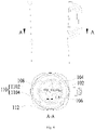
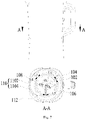
- a food processor 1 including: a cutter head 104, wherein a cutter 106 is arranged on the cutter head 104, the intersecting line of the side wall of the cutter head 104 and the cross section of the cutter head 104 is a cutter head contour line, the largest inscribed circle or the smallest circumscribed circle of the cutter head contour line is a cutter head base circle, and the central axis of the cutter head 104 penetrates the center of the cutter head base circle; and a cup body 102, wherein the cup body 102 is located above the cutter head 104 and arranged on the cutter head 104, the intersecting line of the cup wall of the cup body 102 and the cross section of the cup wall is a cup body contour line 110, the largest inscribed circle or the smallest circumscribed circle of the cup body contour line 110 is a cup body base circle 108, and the central axis of the cup body 102 penetrates the center of the cup body base
- the smallest circumscribed circle refers to a smallest possible circle circumscribed to the actual measured contour, and its center is O; and as shown in Fig. 2 , the largest inscribed circle refers to the largest possible circle inscribed to the actual measured contour, and its center is O'.
- the largest inscribed circles or the smallest circumscribed circles of the cutter head contour line and the cup body contour line are respectively a cutter head base circle of the cutter head contour line, a cup body base circle of the cup body contour line, and the axis of the cutter head and the axis of the cup body respectively penetrate the center of the cutter head base circle and the center of the cup body base circle.
- the distances between any one of different points on the same cup body contour line 110 and the center of the said cup body base circle 108 are unequal, i.e., the cup body contour line 110 is eccentric; and as shown in Figs. 8 and 9 , the distances between any one of different points on the same cutter head contour line and the center of the said cutter head base circle are unequal, i.e., the cutter head contour is also eccentric. That is, the cup body contour is eccentric, and the cutter head contour is also eccentric. Adopting this eccentric technology for stirring food can improve the whirl effect of stirring of the Food Processor. Meanwhile, this structure helps the cutter shatter food better, which improves the stirring performance, making the food taste great and thereby improves the user experience.
- the relative positions of the central axis of the cup body, the central axis of the cutter head and the axis of the cutter are adjusted to realize mutual eccentricity, and the turbulence effect and the stirring performance are further improved via the eccentric technology.
- the cup body 102 of the food processor is provided with an upper opening and a lower opening, and the cross section of the cup body 102 gradually shrinks from top to bottom, i.e., the whole cup body 102 has a certain taper, and the cross section area of the upper end is greater than that of the lower end, so that on the one hand, this helps the cutter shatter food better, and on the other hand, the cup body 102 having a certain taper is beneficial to turbulence, the turbulence effect and shattering effect of food are further improved, and the taste of food is promoted.
- a heating device is arranged on the cutter head 104, and the heating device includes a heating plate, a coil panel, heating coating and the like, wherein the heating plate is of a groove-type structure, the cutter 106 penetrates the said heating device and is arranged in the cutter head, the cup body 102 is located above the heating device, and both the cup body 102 and the cutter head are provided with turbulence rib 112.
- the turbulence effect of stirring is improved, and this helps cutter 106 shatter food better, and then the stirring performance is improved, while making the taste of food great and the user experience is improved.
- the central axis of the cutter head 104 coincides with that of the cup body 102.
- the central axes of the cutter head 104 and the cup body 102 are coincided, so that the cutter head contour is not eccentric, but the cup body 102 contour is eccentric, so that adopting the eccentric structure for stirring food can improve the whirl effect of stirring of Food Processor 1. Meanwhile, this helps cutter 106 shatter foods better, and then the stirring performance is improved, while making the taste of food great, and the user experience is improved. Furthermore, by changing the relative positions of the axis of the cutter, the central axis of the cutter head and the central axis of the cup body, the turbulence effect is improved, and the stirring performance is promoted.
- the central axis of the cutter head 104 and the axis of the cutter 106 coincide with the central axis of the cup body 102.
- the central axis of the cup body 102 penetrating the center O C of the cup body base circle, the axis of the cutter 106 penetrating the cutter axis O K and the central axis of the cutter head 104 penetrating the center O p of the cutter head base circle are coincided, i.e., the cup body 102, the cutter head 104 and the cutter 106 are on the same central axis, thus forming an eccentric structure in which the cup body 102 contour is eccentric, whereas the cutter head 104 contour is not eccentric, and the axis of the cutter is coaxial with the axes of the cup body and the cutter head.
- Adopting such an eccentric structure for stirring food can improve the whirl effect of stirring of Food Processor 1, and this helps cutter 106 shatter food better, and then the stirring performance is improved, while making the taste of food great and the user experience is improved.
- the central axis of the cutter head 104 coincides with that of the cup body 102, and has an eccentric distance of L1 away from the axis of the cutter 106.
- the central axis of the cutter head 104 penetrating the center O p of the cutter head base circle coincides with that of the cup body 102 penetrating the center O C of the cup body base circle, and has an eccentric distance L1 away from the axis of the cutter 106 penetrating the cutter axis O K , i.e., on the basis of the eccentric cup body contour, the axis of the cutter is eccentric relative to the central axis of the cup body and the central axis of the cutter head.
- the whirl effect of stirring is improved, and this helps cutter 106 shatter food better, and then the stirring performance is improved, while making the taste of food great and the user experience is improved.
- the central axis of the cutter head 104 does not coincide with that of the cup body 102.
- the central axis of the cutter head 104 does not coincide with that of the cup body 102, i.e., the axes are relatively eccentric, meanwhile, the cup body 102 contour is eccentric, so that adopting this eccentric structure for stirring food can improve the whirl effect of stirring of Food Processor 1, and this helps cutter 106 shatter food better, and then the stirring performance is improved, while making the taste of food great and the user experience is improved.
- the central axis of the cutter head 104 and the axis of the cutter 106 are coincided, and have an eccentric distance L2 away from the central axis of the cup body 102.
- the central axis of the cutter head 104 penetrating the center O p of the cutter head base circle and the axis of the cutter 106 penetrating through the cutter axis O K are coincided, and have an eccentric distance L2 away from the central axis of the cup body 102 penetrating the center O C of the cup body base circle, i.e., the cup body contour is eccentric, meanwhile, the central axis of the cup body has an eccentric distance L2 relative to the central axis of the cutter head 104 and the axis of the cutter 106.
- the central axis of the cup body 102 coincides with the axis of the cutter 106, and has an eccentric distance L3 away from the central axis of the cutter head 104.
- the central axis of the cup body 102 penetrating through the center O C of the cup body base circle coincides with the axis of the cutter 106 penetrating through the cutter axis O K , and has an eccentric distance of L3 away from the central axis of the cutter head 104 penetrating through the center O P of the cutter head base circle, i.e., the cup body contour is eccentric, and the cup body 102 is coaxial with the cutter 106 and has an eccentric distance L3 away from the central axis of cutter head 104.
- the central axis of the cup body 102 and the central axis of the cutter head 104 have an eccentric distance L4; the central axis of the cutter head 104 and the axis of the cutter 106 have an eccentric distance L5; and the central axis of the cup body 102 and the axis of the cutter 106 have an eccentric distance L6.
- the central axis of the cup body 102 penetrating the center O C of the cup body base circle, the axis of the cutter 106 penetrating the cutter axis O K and the central axis of the cutter head 104 penetrating the center O P of the cutter head base circle all have eccentric distances.
- the distance between any one of central axes refers to the distance between any one of central axes and the intersecting point of any same cross section.
- a contour eccentric distance is further included, which is an absolute value of subtracting the radius of the base circle from the distance between different points on the contour line and the center of the base circle, wherein the contour eccentric distance of the cup body 102 is L7, and the contour eccentric distance of the cutter head is L8.
- the cutter head 102 contour itself is eccentric, and the contour eccentric distance of the cup body 102 is L7; and on the other hand, the contour eccentric distance of the cup body is L7, and the contour eccentric distance of the cutter head is L8.
- the eccentric distance L1, the eccentric distance L2, the eccentric distance L3, the eccentric distance L4, the eccentric distance L5 and the eccentric distance L6 are respectively more than or equal to 0 mm and less than or equal to 50 mm; and the contour eccentric distance L7 of the cup body and the contour eccentric distance L8 of the cutter head are respectively more than or equal to 0 mm and less than or equal to 100 mm.
- the cutter head 104 and the cup body 102 are of an integrated structure or a split structure.
- the cutter head 104 and the cup body 102 are of an integrated structure, so that the stability is good, the installation process is made easy, and the production efficiency is improved; and on the other hand, the cutter head 104 and the cup body 102 are of a split structure to make disassembly and maintenance easy, and in order to ensure the leak tightness of the cutter head 104 and the cup body 102, preferably, a sealing ring is arranged between the cutter head 104 and the cup body 102.
- the cross section of the cup body 102 is a dome and/or the cross section of the cutter head 104 is a dome.
- the cross section of the cup body 102 is a dome; and on the other hand, the cross sections of both the cup body 102 and the cutter head 104 are domes, and the eccentricity is formed via irregular curves, so that the turbulence effect of the cup body 102 is improved, which also helps the cutter 106 shatter food better, and then the stirring performance is improved.
- the dome is an ellipse
- the cross section of the cup body 102 is an ellipse
- the cup body 102 with such a structure is easy to process
- the central axis of the cutter head 104, the central axis of the cutter 106 and the central axis of the cup body 102 are respectively distributed at the two focus points of the ellipse to form eccentricity, so that the structure is simple, and it is easy to operate.
- the turbulence effect of the cup body 102 is further improved, which also helps the cutter 106 shatter food better, and then the stirring performance is improved.
- the ellipse has two focus points F1 and F2, the central axis of the cutter head 104 and the central axis of the cutter 106 may be coaxially distributed at one of the two focuses F1 and F2 of the ellipse, and the central axis of the cup body 102 may be distributed at the other one of the two focuses F1 and F2 of the ellipse; on the other hand, the central axis of the cutter head 104 and the central axis of the cutter 106 are not coaxial but are respectively located at one of the two focuses F1 and F2 of the ellipse, and the central axis of the cup body 102 is coaxial with the central axis of the cutter head 104 or the central axis of the cutter 106; and on a further hand, the central axis of the cutter head 104 and the central axis of the cutter 106 are not coaxial but are respectively located at one of the two focuses F1 and F2 of the
- the protection scope of the present application is not limited thereto, and the distribution positions of the central axis of the cup body 102, the central axis of the cutter head 104 and the central axis of the cutter 106 are set according to specific circumstances and should be set in the goal of achieving the optimal effect.
- the cup wall includes the outer wall and the inner wall of the cup body 102; and the contour line of the cup body 102 is an intersecting line of the outer wall of the cup body 102 and the cross section of the outer wall of the cup body 102, or the contour line of the cup body 102 is an intersecting line of the inner wall of the cup body 102 and the cross section of the inner wall of the cup body 102.
- the contour line of the cup body 102 can be an intersecting line of the outer wall of the cup body 102 and the cross section of the cup wall, i.e., a cup body inner contour line 1104, or an intersecting line of the inner wall of the cup body 102 and the cross section of the cup wall, i.e., a cup body outer contour line 1102.
- the contour line may be obtained through multiple ways, and the distances between different points on the same contour line and the center of the base circle of the said cutter head 104 are unequal, so that an eccentric structure is formed, thereby the whirl effect is improved, and the stirring performance is promoted.
- the cutter 106 includes at least two groups of blades, and each group of blades includes at least two blades 126, wherein the blades 126 of one group of blades extend downward obliquely, and the blades 126 of the other group of blades extend upward obliquely; or the blades 126 of one group of blades extend horizontally, and the blades 126 of the other group of blades extend upward or downward obliquely.
- multiple groups of blades are provided, and the extending angle of each group of blades is different, so that the turbulence effect of the cup body is further improved, the contact area between the cutter 106 and food is increased to realize repeated shattering of the food. Thereby, the food is crushed more thoroughly, the taste of the food is promoted, and user's satisfaction is improved.
- the cutter 106 includes two groups of blades, which are respectively a first group of blades 122 and a second group of blades 124, and each group of blades is composed of two blades 126;
- the blade 126 of the first group of blades 122 includes an oblique part and a horizontal part, the oblique part is close to the central axis of the cutter head, and the horizontal part is away from the central axis of the cutter head; wherein the blades 126 of the first group of blades 122 extend downward obliquely and are arranged below the second group of blades 124, and the blades 126 of the second group of blades 124 extend upward obliquely.
- two groups of blades are provided, wherein the first group of blades 122 is arranged above the second group of blades 124, the blades 126 of the first group of blades 122 extend downward, while the blades 126 of the second group of blades 124 extend upward, i.e., the extending directions are opposite; through setting the blades on the upper two sides, the contact area of the cutter 106 and food is increased sufficiently, and the shattering efficiency is improved; and the extending directions of the blades 126 are set in opposite directions, so that the turbulence effect and the shattering effect at different heights are further improved, the overall food shattering efficiency is improved, the shattering effect is also improved, and the taste of food and the user experience are promoted.
- the first group of blades 122 and the second group of blades 124 are of an integrated structure.
- the two groups of blades are of an integrated structure, so that the overall strength of the cutter 106 is improved, the service reliability of the cutter 106 is guaranteed, and the service life of the cutter 106 is prolonged; Furthermore, the integrated structure of cutter 106 makes maintenance and installation easy, and improves the production efficiency.
- turbulence ribs 112 are arranged in the cup body 102, a cup lid 116 is arranged on the cup body 102, the cup lid 116 is provided with a feed port 118, and a feed cover 120 is arranged on the feed port 118.
- turbulence ribs 112 are arranged in the cup body 102, thus further improving the turbulence effect and the shattering effect; a cup lid 116 is arranged on the cup body 102, thus preventing splashing from the cup body 102 to happen in the food shattering process which may affect the sanitation in the local environment; the cup lid 116 is further provided with a feed port 118, thus making feeding easy, avoiding frequently opening the cup lid 116 and reducing the operating steps; and in order to prevent foreign matters from entering the cup body 102, a feed cover 120 is arranged at the feed port 118, and the feed port 118 is closed via the feed cover 120 after feeding, thus ensuring the sanitation during usage.
- a cup base 114 on which the cup body 102 is arranged is further included, wherein the cup body 102 is connected with the cup base 114 via threads or clamping.
- the cup body 102 is arranged on the cup base 114, and the cup body 102 is connected with the cup base 114 via threads or clamping, so that the structure is simple, assembly and disassembly are made easy, the production efficiency is improved, and the production cost is reduced.
- a sealing ring is arranged between the cutter head 104 and the cup body 102, and the cup body 102 is connected with the cup base 114 via threads to press and fix the cutter head to the bottom of the cup body 102.
- a sealing ring is arranged between the cutter head 104 and the cup body 102, thus ensuring the sealing effect between the cup body 102 and the cutter head 104; and furthermore, the cup body 102 is connected with the cup base 114 via threads to press the cutter head 104 to the bottom of the cup body 102, thus helps to ensure the fixation of the cutter head 104 and to ensure safety during usage.
- the food processor includes a blender, a high speed blender and a juicer.
- the food processor with an eccentric stirring function includes a blender, a high speed blender, a juicer, a soybean milk maker or the like.
- a blender a high speed blender
- a juicer a soybean milk maker or the like.
- the stirring performance is promoted, so that the taste of food is great and the user experience is improved.
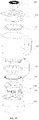
- the blender in a specific embodiment of the food processor mainly includes a cup body assembly, a stirring cutter assembly 106, a cutter head 104 and a stirring cup base 114, wherein the stirring cutter assembly is arranged on the cutter head 104, the cup body assembly is connected with the cutter head 106, and a coupler 134 is arranged on the stirring cup base 114.
- the cup body assembly includes a stirring cup 102 and a cup lid 116 on the stirring cup, the cup lid 116 with a feed port 118, a feed cover 120 with the feed port 118, and a cup lid sealing ring 128 which is arranged between the cup lid 116 and the stirring cup 102; and when the stirring cup 102 and the cutter head 104 are of a split structure, a stirring cup sealing ring 130 and a cutter head sealing ring 132 are arranged between the stirring cup 102 and the cutter head 104.
Landscapes
- Engineering & Computer Science (AREA)
- Food Science & Technology (AREA)
- Mechanical Engineering (AREA)
- Food-Manufacturing Devices (AREA)
Claims (15)
- Robot ménager, comportant :une tête de dispositif de coupe (104), sur laquelle un dispositif de coupe (106) est agencé, la ligne d'intersection de la paroi latérale de la tête de dispositif de coupe (104) et la section transversale de la tête de dispositif de coupe (104) est une ligne de contour de la tête de dispositif de coupe, le cercle inscrit le plus grand ou le cercle circonscrit le plus petit de la ligne de contour de la tête de dispositif de coupe est un cercle de base de la tête de dispositif de coupe, et l'axe central de la tête de dispositif de coupe (104) passe au travers du centre du cercle de base de la tête de dispositif de coupe ; etun corps de coupelle (102), dans lequel le corps de coupelle (102) est situé au-dessus de la tête de dispositif de coupe (104) et agencé sur la tête de dispositif de coupe (104), la ligne d'intersection de la paroi de coupelle du corps de coupelle (102) et la section transversale de la paroi de coupelle est une ligne de contour de corps de coupelle (110), le cercle inscrit le plus grand ou le cercle circonscrit le plus petit de la ligne de contour de corps de coupelle (110) est un cercle de base de corps de coupelle (108), et l'axe central du corps de coupelle (102) passe au travers du centre du cercle de base de corps de coupelle (108),dans lequel les distances entre l'un quelconque des différents points sur la même ligne de contour de corps de coupelle (110) et le centre du cercle de base de corps de coupelle (108) ne sont pas égales ;caractérisé en ce queles distances entre l'un quelconque des différents points sur la même ligne de contour de tête de dispositif de coupe et le centre du cercle de base de la tête de dispositif de coupe ne sont pas égales.
- Robot ménager selon la revendication 1, dans lequel :
l'axe central de la tête de dispositif de coupe (104) coïncide avec celui du corps de coupelle (102). - Robot ménager selon la revendication 2, dans lequel :
l'axe central de la tête de dispositif de coupe (104) et l'axe du dispositif de coupe (106) coïncident avec l'axe central du corps de coupelle (102). - Robot ménager selon la revendication 2, dans lequel :
l'axe central de ladite tête de dispositif de coupe (104) coïncide avec celui du corps de coupelle (102), et a une distance excentrique L1 par rapport à l'axe du dispositif de coupe (106), dans lequel la distance excentrique L1 est supérieure ou égale à 0 mm et inférieure ou égale à 50 mm. - Robot ménager selon la revendication 1, dans lequel :
l'axe central de la tête de dispositif de coupe (104) ne coïncide pas avec celui du corps de coupelle (102). - Robot ménager selon la revendication 5, dans lequel :
l'axe central de la tête de dispositif de coupe (104) coïncide avec l'axe du dispositif de coupe (106), et a une distance excentrique L2 par rapport à l'axe central du corps de coupelle (102), dans lequel la distance excentrique L2 est supérieure ou égale à 0 mm et inférieure ou égale à 50 mm. - Robot ménager selon la revendication 5, dans lequel :
l'axe central du corps de coupelle (102) coïncide avec l'axe du dispositif de coupe (106), et a une distance excentrique L3 par rapport à l'axe central de la tête de dispositif de coupe (104), dans lequel la distance excentrique L3 est supérieure ou égale à 0 mm et inférieure ou égale à 50 mm. - Robot ménager selon la revendication 5, dans lequel :l'axe central du corps de coupelle (102) a une distance excentrique L4 par rapport à l'axe central de la tête de dispositif de coupe (104) ;l'axe central de la tête de dispositif de coupe (104) a une distance excentrique L5 par rapport à l'axe du dispositif de coupe (106) ; etl'axe central du corps de coupelle (102) a une distance excentrique L6 par rapport à l'axe du dispositif de coupe (106), dans lequel la distance excentrique L4, la distance excentrique L5 et la distance excentrique L6 sont supérieures ou égales à 0 mm et inférieures ou égales à 50 mm respectivement.
- Robot ménager selon la revendication 1, comportant par ailleurs :une distance excentrique de contour, qui est une valeur absolue d'une valeur obtenue en soustrayant le rayon du cercle de base de la distance entre différents points sur les lignes de contour et le centre du cercle de base,dans lequel la distance excentrique de contour du corps de coupelle (102) L7 est une valeur absolue d'une valeur obtenue en soustrayant le rayon du cercle de base du corps de coupelle (102) de la distance entre différents points sur les lignes de contour du corps de coupelle (102) et le centre du cercle de base du corps de coupelle (102), et la distance excentrique de contour de la tête de dispositif de coupe L8 est une valeur absolue d'une valeur obtenue en soustrayant le rayon du cercle de base de la tête de dispositif de coupe (104) de la distance entre différents points sur les lignes de contour de la tête de dispositif de coupe (104) et le centre du cercle de base de la tête de dispositif de coupe (104), la distance excentrique de contour L7 du corps de coupelle (102) et la distance excentrique de contour L8 de la tête de dispositif de coupe (104) sont supérieures ou égales à 0 mm et inférieures ou égales à 100 mm respectivement.
- Robot ménager selon l'une quelconque des revendications 1 à 9, dans lequel la tête de dispositif de coupe (104) et le corps de coupelle (102) forment une structure d'un seul tenant ou une structure divisée.
- Robot ménager selon l'une quelconque des revendications 1 à 9, dans lequel
la section transversale du corps de coupelle (102) est un dôme et/ou la section transversale de la tête de dispositif de coupe (104) est un dôme. - Robot ménager selon l'une quelconque des revendications 1 à 9, dans lequella paroi de coupelle comporte une paroi extérieure et une paroi intérieure du corps de coupelle (102) ;la ligne de contour du corps de coupelle (102) est une ligne d'intersection de la paroi extérieure du corps de coupelle (102) et de la section transversale de la paroi extérieure du corps de coupelle (102),ou la ligne de contour du corps de coupelle (102) est une ligne d'intersection de la paroi intérieure du corps de coupelle (102) et de la section transversale de la paroi intérieure du corps de coupelle (102).
- Robot ménager selon l'une quelconque des revendications 1 à 9, dans lequel le dispositif de coupe (106) comporte au moins deux groupes de lames, et chaque groupe de lames comporte au moins deux lames (126) ;
dans lequel les lames (126) d'un groupe de lames s'étendent vers le bas de manière oblique, et les lames (126) de l'autre groupe de lames s'étendent vers le haut de manière oblique ; ou les lames (126) d'un groupe de lames s'étendent à l'horizontale, et les lames (126) de l'autre groupe de lames s'étendent vers le haut ou vers le bas de manière oblique. - Robot ménager selon la revendication 13, dans lequelle dispositif de coupe (106) comporte deux groupes de lames (126), qui sont un premier groupe de lames (122) et un deuxième groupe de lames (124) respectivement, dont chacun est composé de deux lames à aile (126) ;les lames (126) du premier groupe de lames (122) comportent une partie oblique et une partie horizontale, la partie oblique se trouve à proximité de l'axe central de la tête de dispositif de coupe (104), et la partie horizontale se trouve à distance de l'axe central de la tête de dispositif de coupe (104) ;dans lequel les lames du premier groupe de lames (122) s'étendent vers le bas de manière oblique et sont agencées sous le deuxième groupe de lames (124), et les lames (126) du deuxième groupe de lames (124) s'étendent vers le haut de manière oblique.
- Robot ménager selon la revendication 14, dans lequel le premier groupe de lames (122) et le deuxième groupe de lames (124) forment une structure d'un seul tenant.
Applications Claiming Priority (5)
| Application Number | Priority Date | Filing Date | Title |
|---|---|---|---|
| CN201610968428.4A CN108013792B (zh) | 2016-10-28 | 2016-10-28 | 食物料理机 |
| CN201610971493.2A CN108013789B (zh) | 2016-10-28 | 2016-10-28 | 食物料理机 |
| CN201621195265.2U CN206565828U (zh) | 2016-10-28 | 2016-10-28 | 食物料理机 |
| CN201621186043.4U CN206565826U (zh) | 2016-10-28 | 2016-10-28 | 食物料理机 |
| PCT/CN2016/107801 WO2018076435A1 (fr) | 2016-10-28 | 2016-11-29 | Robot ménager |
Publications (3)
| Publication Number | Publication Date |
|---|---|
| EP3476262A1 EP3476262A1 (fr) | 2019-05-01 |
| EP3476262A4 EP3476262A4 (fr) | 2019-06-05 |
| EP3476262B1 true EP3476262B1 (fr) | 2022-08-03 |
Family
ID=62024361
Family Applications (1)
| Application Number | Title | Priority Date | Filing Date |
|---|---|---|---|
| EP16919995.7A Active EP3476262B1 (fr) | 2016-10-28 | 2016-11-29 | Robot ménager |
Country Status (7)
| Country | Link |
|---|---|
| US (1) | US10786117B2 (fr) |
| EP (1) | EP3476262B1 (fr) |
| JP (1) | JP6807452B2 (fr) |
| KR (1) | KR102188428B1 (fr) |
| CA (1) | CA3035998C (fr) |
| TW (1) | TWI643591B (fr) |
| WO (1) | WO2018076435A1 (fr) |
Families Citing this family (1)
| Publication number | Priority date | Publication date | Assignee | Title |
|---|---|---|---|---|
| EP3476263B1 (fr) * | 2016-10-28 | 2021-09-08 | Guangdong Midea Consumer Electrics Manufacturing Co., Ltd. | Robot ménager |
Family Cites Families (27)
| Publication number | Priority date | Publication date | Assignee | Title |
|---|---|---|---|---|
| JPH05253084A (ja) * | 1992-03-12 | 1993-10-05 | Matsushita Electric Ind Co Ltd | 回転調理器 |
| US6092922A (en) * | 1999-06-29 | 2000-07-25 | Whirlpool Corporation | Food blender with a balanced blade |
| JP3702769B2 (ja) * | 2000-09-28 | 2005-10-05 | 松下電器産業株式会社 | 電動調理機 |
| US7063456B2 (en) * | 2001-06-26 | 2006-06-20 | Vita-Mix Corporation | Container for a blender |
| US7350963B2 (en) * | 2005-02-04 | 2008-04-01 | Hamilton Beach Brands, Inc. | Blender jar |
| CN2817665Y (zh) | 2005-08-26 | 2006-09-20 | 律展企业股份有限公司 | 果菜机的刀具装置 |
| CN102743110B (zh) * | 2005-09-05 | 2015-07-01 | 布瑞威利私人有限公司 | 具有匹配的壶和刀片的改进搅拌机 |
| FR2925279B1 (fr) * | 2007-12-19 | 2012-08-10 | Seb Sa | Recipient de travail pour appareil electromenager de preparation culinaire et appareil muni d'un tel recipient |
| FR2925278B1 (fr) * | 2007-12-19 | 2012-08-31 | Seb Sa | Recipient de travail pour appareil electromenager de preparation culinaire et appareil muni d'un tel recipient |
| US8529120B2 (en) * | 2008-03-18 | 2013-09-10 | Vita-Mix Corporation | Blender container and cover |
| CN201905766U (zh) | 2010-12-09 | 2011-07-27 | 广东新宝电器股份有限公司 | 食物处理器或搅拌器 |
| EP2486833B8 (fr) * | 2011-02-10 | 2018-08-15 | Main Power InnoTech (Shenzhen) Manufacturing Co. Ltd. | Cuve de mélange |
| CN102670092B (zh) * | 2011-03-09 | 2017-01-25 | 主力智业(深圳)电器实业有限公司 | 混合容器 |
| US8550695B2 (en) * | 2011-09-23 | 2013-10-08 | Whirlpool Corporation | Blender with varying internally and externally shaped container |
| US8721165B2 (en) * | 2011-09-23 | 2014-05-13 | Whirlpool Corporation | Blender with varying internally and externally shaped container |
| FR2986956B1 (fr) * | 2012-02-21 | 2014-03-28 | Santos | Bol de traitement d'aliments pour un melangeur |
| GB2501499A (en) * | 2012-04-25 | 2013-10-30 | Kenwood Ltd | Electric blender having a goblet with adjustable longitudinal axis for disruption of a vortex during blending. |
| EP2735252B1 (fr) * | 2012-11-21 | 2015-10-21 | Wen-Ching Lee | Récipient destiné à un mélangeur d'aliments |
| GB2508236B (en) * | 2012-11-27 | 2016-06-01 | Kenwood Ltd | Blade driving assembly for food processor and food processor incorporating same |
| US9814357B2 (en) * | 2013-03-14 | 2017-11-14 | Spectrum Brands, Inc. | Container and blade arrangement for food preparation appliance |
| CN203987646U (zh) * | 2014-08-11 | 2014-12-10 | 广东美的生活电器制造有限公司 | 豆浆机粉碎容器组件 |
| CN204889746U (zh) * | 2015-07-13 | 2015-12-23 | 浙江绍兴苏泊尔生活电器有限公司 | 粉碎刀组及具有其的料理机 |
| CN204839230U (zh) * | 2015-07-30 | 2015-12-09 | 广东新宝电器股份有限公司 | 一种偏心研磨的食材处理设备 |
| CN108013789B (zh) | 2016-10-28 | 2021-03-02 | 广东美的生活电器制造有限公司 | 食物料理机 |
| CN206565828U (zh) | 2016-10-28 | 2017-10-20 | 广东美的生活电器制造有限公司 | 食物料理机 |
| CN108013792B (zh) | 2016-10-28 | 2021-03-02 | 广东美的生活电器制造有限公司 | 食物料理机 |
| CN206565826U (zh) | 2016-10-28 | 2017-10-20 | 广东美的生活电器制造有限公司 | 食物料理机 |
-
2016
- 2016-11-29 CA CA3035998A patent/CA3035998C/fr active Active
- 2016-11-29 JP JP2019515653A patent/JP6807452B2/ja active Active
- 2016-11-29 EP EP16919995.7A patent/EP3476262B1/fr active Active
- 2016-11-29 WO PCT/CN2016/107801 patent/WO2018076435A1/fr not_active Ceased
- 2016-11-29 KR KR1020197006765A patent/KR102188428B1/ko active Active
-
2017
- 2017-10-16 TW TW106135314A patent/TWI643591B/zh active
-
2019
- 2019-01-28 US US16/259,971 patent/US10786117B2/en active Active
Also Published As
| Publication number | Publication date |
|---|---|
| KR102188428B1 (ko) | 2020-12-08 |
| EP3476262A4 (fr) | 2019-06-05 |
| CA3035998C (fr) | 2022-09-27 |
| US20190150670A1 (en) | 2019-05-23 |
| KR20190039205A (ko) | 2019-04-10 |
| TWI643591B (zh) | 2018-12-11 |
| CA3035998A1 (fr) | 2018-05-03 |
| WO2018076435A1 (fr) | 2018-05-03 |
| US10786117B2 (en) | 2020-09-29 |
| JP6807452B2 (ja) | 2021-01-06 |
| JP2019528924A (ja) | 2019-10-17 |
| TW201815338A (zh) | 2018-05-01 |
| EP3476262A1 (fr) | 2019-05-01 |
Similar Documents
| Publication | Publication Date | Title |
|---|---|---|
| US11602243B2 (en) | Food processor | |
| US8800905B2 (en) | Mixing vessel | |
| US10765260B2 (en) | Container and blade arrangement for food preparation appliance | |
| EP2486833B1 (fr) | Cuve de mélange | |
| CN102670092B (zh) | 混合容器 | |
| CN107296527B (zh) | 食物料理机 | |
| EP3476262B1 (fr) | Robot ménager | |
| CN208447351U (zh) | 料理机 | |
| CN108013792B (zh) | 食物料理机 | |
| CN206565828U (zh) | 食物料理机 | |
| CN107296533B (zh) | 食物料理机 | |
| CN206565826U (zh) | 食物料理机 | |
| CN204318442U (zh) | 豆浆机 | |
| CN108685488A (zh) | 一种食品加工机 | |
| CN102551495B (zh) | 果汁机 | |
| CN207202726U (zh) | 一种豆浆机 | |
| CN206354932U (zh) | 食物料理机 | |
| CN206354934U (zh) | 食物料理机 | |
| HK1248492A1 (zh) | 食物料理机 | |
| HK1245043A1 (zh) | 食物料理机 | |
| CN202426349U (zh) | 用于食物搅拌机搅拌头的防护罩以及搅拌头和搅拌机 | |
| CN207202728U (zh) | 一种豆浆机 | |
| CN105725788A (zh) | 豆浆机 |
Legal Events
| Date | Code | Title | Description |
|---|---|---|---|
| STAA | Information on the status of an ep patent application or granted ep patent |
Free format text: STATUS: THE INTERNATIONAL PUBLICATION HAS BEEN MADE |
|
| PUAI | Public reference made under article 153(3) epc to a published international application that has entered the european phase |
Free format text: ORIGINAL CODE: 0009012 |
|
| STAA | Information on the status of an ep patent application or granted ep patent |
Free format text: STATUS: REQUEST FOR EXAMINATION WAS MADE |
|
| 17P | Request for examination filed |
Effective date: 20190122 |
|
| AK | Designated contracting states |
Kind code of ref document: A1 Designated state(s): AL AT BE BG CH CY CZ DE DK EE ES FI FR GB GR HR HU IE IS IT LI LT LU LV MC MK MT NL NO PL PT RO RS SE SI SK SM TR |
|
| AX | Request for extension of the european patent |
Extension state: BA ME |
|
| A4 | Supplementary search report drawn up and despatched |
Effective date: 20190508 |
|
| RIC1 | Information provided on ipc code assigned before grant |
Ipc: A47J 43/07 20060101ALI20190502BHEP Ipc: A47J 43/046 20060101AFI20190502BHEP |
|
| DAV | Request for validation of the european patent (deleted) | ||
| DAX | Request for extension of the european patent (deleted) | ||
| GRAP | Despatch of communication of intention to grant a patent |
Free format text: ORIGINAL CODE: EPIDOSNIGR1 |
|
| STAA | Information on the status of an ep patent application or granted ep patent |
Free format text: STATUS: GRANT OF PATENT IS INTENDED |
|
| INTG | Intention to grant announced |
Effective date: 20220426 |
|
| GRAS | Grant fee paid |
Free format text: ORIGINAL CODE: EPIDOSNIGR3 |
|
| GRAA | (expected) grant |
Free format text: ORIGINAL CODE: 0009210 |
|
| STAA | Information on the status of an ep patent application or granted ep patent |
Free format text: STATUS: THE PATENT HAS BEEN GRANTED |
|
| AK | Designated contracting states |
Kind code of ref document: B1 Designated state(s): AL AT BE BG CH CY CZ DE DK EE ES FI FR GB GR HR HU IE IS IT LI LT LU LV MC MK MT NL NO PL PT RO RS SE SI SK SM TR |
|
| REG | Reference to a national code |
Ref country code: AT Ref legal event code: REF Ref document number: 1508071 Country of ref document: AT Kind code of ref document: T Effective date: 20220815 Ref country code: CH Ref legal event code: EP |
|
| REG | Reference to a national code |
Ref country code: DE Ref legal event code: R096 Ref document number: 602016074074 Country of ref document: DE |
|
| REG | Reference to a national code |
Ref country code: IE Ref legal event code: FG4D |
|
| REG | Reference to a national code |
Ref country code: LT Ref legal event code: MG9D |
|
| REG | Reference to a national code |
Ref country code: NL Ref legal event code: MP Effective date: 20220803 |
|
| PG25 | Lapsed in a contracting state [announced via postgrant information from national office to epo] |
Ref country code: SE Free format text: LAPSE BECAUSE OF FAILURE TO SUBMIT A TRANSLATION OF THE DESCRIPTION OR TO PAY THE FEE WITHIN THE PRESCRIBED TIME-LIMIT Effective date: 20220803 Ref country code: RS Free format text: LAPSE BECAUSE OF FAILURE TO SUBMIT A TRANSLATION OF THE DESCRIPTION OR TO PAY THE FEE WITHIN THE PRESCRIBED TIME-LIMIT Effective date: 20220803 Ref country code: PT Free format text: LAPSE BECAUSE OF FAILURE TO SUBMIT A TRANSLATION OF THE DESCRIPTION OR TO PAY THE FEE WITHIN THE PRESCRIBED TIME-LIMIT Effective date: 20221205 Ref country code: NO Free format text: LAPSE BECAUSE OF FAILURE TO SUBMIT A TRANSLATION OF THE DESCRIPTION OR TO PAY THE FEE WITHIN THE PRESCRIBED TIME-LIMIT Effective date: 20221103 Ref country code: NL Free format text: LAPSE BECAUSE OF FAILURE TO SUBMIT A TRANSLATION OF THE DESCRIPTION OR TO PAY THE FEE WITHIN THE PRESCRIBED TIME-LIMIT Effective date: 20220803 Ref country code: LV Free format text: LAPSE BECAUSE OF FAILURE TO SUBMIT A TRANSLATION OF THE DESCRIPTION OR TO PAY THE FEE WITHIN THE PRESCRIBED TIME-LIMIT Effective date: 20220803 Ref country code: LT Free format text: LAPSE BECAUSE OF FAILURE TO SUBMIT A TRANSLATION OF THE DESCRIPTION OR TO PAY THE FEE WITHIN THE PRESCRIBED TIME-LIMIT Effective date: 20220803 Ref country code: FI Free format text: LAPSE BECAUSE OF FAILURE TO SUBMIT A TRANSLATION OF THE DESCRIPTION OR TO PAY THE FEE WITHIN THE PRESCRIBED TIME-LIMIT Effective date: 20220803 Ref country code: ES Free format text: LAPSE BECAUSE OF FAILURE TO SUBMIT A TRANSLATION OF THE DESCRIPTION OR TO PAY THE FEE WITHIN THE PRESCRIBED TIME-LIMIT Effective date: 20220803 |
|
| REG | Reference to a national code |
Ref country code: AT Ref legal event code: MK05 Ref document number: 1508071 Country of ref document: AT Kind code of ref document: T Effective date: 20220803 |
|
| PG25 | Lapsed in a contracting state [announced via postgrant information from national office to epo] |
Ref country code: PL Free format text: LAPSE BECAUSE OF FAILURE TO SUBMIT A TRANSLATION OF THE DESCRIPTION OR TO PAY THE FEE WITHIN THE PRESCRIBED TIME-LIMIT Effective date: 20220803 Ref country code: IS Free format text: LAPSE BECAUSE OF FAILURE TO SUBMIT A TRANSLATION OF THE DESCRIPTION OR TO PAY THE FEE WITHIN THE PRESCRIBED TIME-LIMIT Effective date: 20221203 Ref country code: HR Free format text: LAPSE BECAUSE OF FAILURE TO SUBMIT A TRANSLATION OF THE DESCRIPTION OR TO PAY THE FEE WITHIN THE PRESCRIBED TIME-LIMIT Effective date: 20220803 Ref country code: GR Free format text: LAPSE BECAUSE OF FAILURE TO SUBMIT A TRANSLATION OF THE DESCRIPTION OR TO PAY THE FEE WITHIN THE PRESCRIBED TIME-LIMIT Effective date: 20221104 |
|
| PG25 | Lapsed in a contracting state [announced via postgrant information from national office to epo] |
Ref country code: SM Free format text: LAPSE BECAUSE OF FAILURE TO SUBMIT A TRANSLATION OF THE DESCRIPTION OR TO PAY THE FEE WITHIN THE PRESCRIBED TIME-LIMIT Effective date: 20220803 Ref country code: RO Free format text: LAPSE BECAUSE OF FAILURE TO SUBMIT A TRANSLATION OF THE DESCRIPTION OR TO PAY THE FEE WITHIN THE PRESCRIBED TIME-LIMIT Effective date: 20220803 Ref country code: DK Free format text: LAPSE BECAUSE OF FAILURE TO SUBMIT A TRANSLATION OF THE DESCRIPTION OR TO PAY THE FEE WITHIN THE PRESCRIBED TIME-LIMIT Effective date: 20220803 Ref country code: CZ Free format text: LAPSE BECAUSE OF FAILURE TO SUBMIT A TRANSLATION OF THE DESCRIPTION OR TO PAY THE FEE WITHIN THE PRESCRIBED TIME-LIMIT Effective date: 20220803 Ref country code: AT Free format text: LAPSE BECAUSE OF FAILURE TO SUBMIT A TRANSLATION OF THE DESCRIPTION OR TO PAY THE FEE WITHIN THE PRESCRIBED TIME-LIMIT Effective date: 20220803 |
|
| REG | Reference to a national code |
Ref country code: DE Ref legal event code: R097 Ref document number: 602016074074 Country of ref document: DE |
|
| PG25 | Lapsed in a contracting state [announced via postgrant information from national office to epo] |
Ref country code: SK Free format text: LAPSE BECAUSE OF FAILURE TO SUBMIT A TRANSLATION OF THE DESCRIPTION OR TO PAY THE FEE WITHIN THE PRESCRIBED TIME-LIMIT Effective date: 20220803 Ref country code: EE Free format text: LAPSE BECAUSE OF FAILURE TO SUBMIT A TRANSLATION OF THE DESCRIPTION OR TO PAY THE FEE WITHIN THE PRESCRIBED TIME-LIMIT Effective date: 20220803 |
|
| PLBE | No opposition filed within time limit |
Free format text: ORIGINAL CODE: 0009261 |
|
| STAA | Information on the status of an ep patent application or granted ep patent |
Free format text: STATUS: NO OPPOSITION FILED WITHIN TIME LIMIT |
|
| PG25 | Lapsed in a contracting state [announced via postgrant information from national office to epo] |
Ref country code: MC Free format text: LAPSE BECAUSE OF FAILURE TO SUBMIT A TRANSLATION OF THE DESCRIPTION OR TO PAY THE FEE WITHIN THE PRESCRIBED TIME-LIMIT Effective date: 20220803 Ref country code: AL Free format text: LAPSE BECAUSE OF FAILURE TO SUBMIT A TRANSLATION OF THE DESCRIPTION OR TO PAY THE FEE WITHIN THE PRESCRIBED TIME-LIMIT Effective date: 20220803 |
|
| REG | Reference to a national code |
Ref country code: CH Ref legal event code: PL |
|
| 26N | No opposition filed |
Effective date: 20230504 |
|
| REG | Reference to a national code |
Ref country code: BE Ref legal event code: MM Effective date: 20221130 |
|
| PG25 | Lapsed in a contracting state [announced via postgrant information from national office to epo] |
Ref country code: LI Free format text: LAPSE BECAUSE OF NON-PAYMENT OF DUE FEES Effective date: 20221130 Ref country code: CH Free format text: LAPSE BECAUSE OF NON-PAYMENT OF DUE FEES Effective date: 20221130 |
|
| PG25 | Lapsed in a contracting state [announced via postgrant information from national office to epo] |
Ref country code: SI Free format text: LAPSE BECAUSE OF FAILURE TO SUBMIT A TRANSLATION OF THE DESCRIPTION OR TO PAY THE FEE WITHIN THE PRESCRIBED TIME-LIMIT Effective date: 20220803 Ref country code: LU Free format text: LAPSE BECAUSE OF NON-PAYMENT OF DUE FEES Effective date: 20221129 |
|
| PG25 | Lapsed in a contracting state [announced via postgrant information from national office to epo] |
Ref country code: IE Free format text: LAPSE BECAUSE OF NON-PAYMENT OF DUE FEES Effective date: 20221129 |
|
| PG25 | Lapsed in a contracting state [announced via postgrant information from national office to epo] |
Ref country code: BE Free format text: LAPSE BECAUSE OF NON-PAYMENT OF DUE FEES Effective date: 20221130 |
|
| PG25 | Lapsed in a contracting state [announced via postgrant information from national office to epo] |
Ref country code: HU Free format text: LAPSE BECAUSE OF FAILURE TO SUBMIT A TRANSLATION OF THE DESCRIPTION OR TO PAY THE FEE WITHIN THE PRESCRIBED TIME-LIMIT; INVALID AB INITIO Effective date: 20161129 |
|
| PG25 | Lapsed in a contracting state [announced via postgrant information from national office to epo] |
Ref country code: CY Free format text: LAPSE BECAUSE OF FAILURE TO SUBMIT A TRANSLATION OF THE DESCRIPTION OR TO PAY THE FEE WITHIN THE PRESCRIBED TIME-LIMIT Effective date: 20220803 |
|
| PG25 | Lapsed in a contracting state [announced via postgrant information from national office to epo] |
Ref country code: MK Free format text: LAPSE BECAUSE OF FAILURE TO SUBMIT A TRANSLATION OF THE DESCRIPTION OR TO PAY THE FEE WITHIN THE PRESCRIBED TIME-LIMIT Effective date: 20220803 Ref country code: IT Free format text: LAPSE BECAUSE OF FAILURE TO SUBMIT A TRANSLATION OF THE DESCRIPTION OR TO PAY THE FEE WITHIN THE PRESCRIBED TIME-LIMIT Effective date: 20220803 |
|
| PG25 | Lapsed in a contracting state [announced via postgrant information from national office to epo] |
Ref country code: TR Free format text: LAPSE BECAUSE OF FAILURE TO SUBMIT A TRANSLATION OF THE DESCRIPTION OR TO PAY THE FEE WITHIN THE PRESCRIBED TIME-LIMIT Effective date: 20220803 |
|
| PG25 | Lapsed in a contracting state [announced via postgrant information from national office to epo] |
Ref country code: BG Free format text: LAPSE BECAUSE OF FAILURE TO SUBMIT A TRANSLATION OF THE DESCRIPTION OR TO PAY THE FEE WITHIN THE PRESCRIBED TIME-LIMIT Effective date: 20220803 |
|
| PG25 | Lapsed in a contracting state [announced via postgrant information from national office to epo] |
Ref country code: MT Free format text: LAPSE BECAUSE OF FAILURE TO SUBMIT A TRANSLATION OF THE DESCRIPTION OR TO PAY THE FEE WITHIN THE PRESCRIBED TIME-LIMIT Effective date: 20220803 |
|
| PGFP | Annual fee paid to national office [announced via postgrant information from national office to epo] |
Ref country code: DE Payment date: 20241122 Year of fee payment: 9 |
|
| PGFP | Annual fee paid to national office [announced via postgrant information from national office to epo] |
Ref country code: GB Payment date: 20241122 Year of fee payment: 9 |
|
| PGFP | Annual fee paid to national office [announced via postgrant information from national office to epo] |
Ref country code: FR Payment date: 20241122 Year of fee payment: 9 |