EP3476286A1 - Vorrichtung zur bereitstellung von elektrokardiographischen und insbesondere von arrhythmieinformationen - Google Patents
Vorrichtung zur bereitstellung von elektrokardiographischen und insbesondere von arrhythmieinformationen Download PDFInfo
- Publication number
- EP3476286A1 EP3476286A1 EP18201568.5A EP18201568A EP3476286A1 EP 3476286 A1 EP3476286 A1 EP 3476286A1 EP 18201568 A EP18201568 A EP 18201568A EP 3476286 A1 EP3476286 A1 EP 3476286A1
- Authority
- EP
- European Patent Office
- Prior art keywords
- esophageal
- heart
- plot
- potential
- arrow
- Prior art date
- Legal status (The legal status is an assumption and is not a legal conclusion. Google has not performed a legal analysis and makes no representation as to the accuracy of the status listed.)
- Granted
Links
Images


Classifications
-
- A—HUMAN NECESSITIES
- A61—MEDICAL OR VETERINARY SCIENCE; HYGIENE
- A61B—DIAGNOSIS; SURGERY; IDENTIFICATION
- A61B5/00—Measuring for diagnostic purposes; Identification of persons
- A61B5/24—Detecting, measuring or recording bioelectric or biomagnetic signals of the body or parts thereof
- A61B5/25—Bioelectric electrodes therefor
- A61B5/279—Bioelectric electrodes therefor specially adapted for particular uses
- A61B5/28—Bioelectric electrodes therefor specially adapted for particular uses for electrocardiography [ECG]
- A61B5/283—Invasive
- A61B5/285—Endotracheal, oesophageal or gastric probes
-
- A—HUMAN NECESSITIES
- A61—MEDICAL OR VETERINARY SCIENCE; HYGIENE
- A61B—DIAGNOSIS; SURGERY; IDENTIFICATION
- A61B5/00—Measuring for diagnostic purposes; Identification of persons
- A61B5/24—Detecting, measuring or recording bioelectric or biomagnetic signals of the body or parts thereof
- A61B5/316—Modalities, i.e. specific diagnostic methods
- A61B5/318—Heart-related electrical modalities, e.g. electrocardiography [ECG]
- A61B5/339—Displays specially adapted therefor
- A61B5/343—Potential distribution indication
-
- A—HUMAN NECESSITIES
- A61—MEDICAL OR VETERINARY SCIENCE; HYGIENE
- A61B—DIAGNOSIS; SURGERY; IDENTIFICATION
- A61B5/00—Measuring for diagnostic purposes; Identification of persons
- A61B5/24—Detecting, measuring or recording bioelectric or biomagnetic signals of the body or parts thereof
- A61B5/316—Modalities, i.e. specific diagnostic methods
- A61B5/318—Heart-related electrical modalities, e.g. electrocardiography [ECG]
- A61B5/346—Analysis of electrocardiograms
- A61B5/349—Detecting specific parameters of the electrocardiograph cycle
- A61B5/366—Detecting abnormal QRS complex, e.g. widening
-
- A—HUMAN NECESSITIES
- A61—MEDICAL OR VETERINARY SCIENCE; HYGIENE
- A61B—DIAGNOSIS; SURGERY; IDENTIFICATION
- A61B5/00—Measuring for diagnostic purposes; Identification of persons
- A61B5/24—Detecting, measuring or recording bioelectric or biomagnetic signals of the body or parts thereof
- A61B5/316—Modalities, i.e. specific diagnostic methods
- A61B5/318—Heart-related electrical modalities, e.g. electrocardiography [ECG]
- A61B5/367—Electrophysiological study [EPS], e.g. electrical activation mapping or electro-anatomical mapping
-
- A—HUMAN NECESSITIES
- A61—MEDICAL OR VETERINARY SCIENCE; HYGIENE
- A61B—DIAGNOSIS; SURGERY; IDENTIFICATION
- A61B2560/00—Constructional details of operational features of apparatus; Accessories for medical measuring apparatus
- A61B2560/04—Constructional details of apparatus
- A61B2560/0462—Apparatus with built-in sensors
- A61B2560/0468—Built-in electrodes
-
- A—HUMAN NECESSITIES
- A61—MEDICAL OR VETERINARY SCIENCE; HYGIENE
- A61B—DIAGNOSIS; SURGERY; IDENTIFICATION
- A61B5/00—Measuring for diagnostic purposes; Identification of persons
- A61B5/24—Detecting, measuring or recording bioelectric or biomagnetic signals of the body or parts thereof
- A61B5/316—Modalities, i.e. specific diagnostic methods
- A61B5/318—Heart-related electrical modalities, e.g. electrocardiography [ECG]
- A61B5/346—Analysis of electrocardiograms
- A61B5/349—Detecting specific parameters of the electrocardiograph cycle
- A61B5/363—Detecting tachycardia or bradycardia
-
- A—HUMAN NECESSITIES
- A61—MEDICAL OR VETERINARY SCIENCE; HYGIENE
- A61B—DIAGNOSIS; SURGERY; IDENTIFICATION
- A61B5/00—Measuring for diagnostic purposes; Identification of persons
- A61B5/24—Detecting, measuring or recording bioelectric or biomagnetic signals of the body or parts thereof
- A61B5/316—Modalities, i.e. specific diagnostic methods
- A61B5/318—Heart-related electrical modalities, e.g. electrocardiography [ECG]
- A61B5/346—Analysis of electrocardiograms
- A61B5/349—Detecting specific parameters of the electrocardiograph cycle
- A61B5/364—Detecting abnormal ECG interval, e.g. extrasystoles, ectopic heartbeats
-
- A—HUMAN NECESSITIES
- A61—MEDICAL OR VETERINARY SCIENCE; HYGIENE
- A61B—DIAGNOSIS; SURGERY; IDENTIFICATION
- A61B5/00—Measuring for diagnostic purposes; Identification of persons
- A61B5/72—Signal processing specially adapted for physiological signals or for diagnostic purposes
- A61B5/7203—Signal processing specially adapted for physiological signals or for diagnostic purposes for noise prevention, reduction or removal
-
- A—HUMAN NECESSITIES
- A61—MEDICAL OR VETERINARY SCIENCE; HYGIENE
- A61B—DIAGNOSIS; SURGERY; IDENTIFICATION
- A61B5/00—Measuring for diagnostic purposes; Identification of persons
- A61B5/72—Signal processing specially adapted for physiological signals or for diagnostic purposes
- A61B5/7203—Signal processing specially adapted for physiological signals or for diagnostic purposes for noise prevention, reduction or removal
- A61B5/7207—Signal processing specially adapted for physiological signals or for diagnostic purposes for noise prevention, reduction or removal of noise induced by motion artifacts
-
- A—HUMAN NECESSITIES
- A61—MEDICAL OR VETERINARY SCIENCE; HYGIENE
- A61B—DIAGNOSIS; SURGERY; IDENTIFICATION
- A61B5/00—Measuring for diagnostic purposes; Identification of persons
- A61B5/72—Signal processing specially adapted for physiological signals or for diagnostic purposes
- A61B5/7232—Signal processing specially adapted for physiological signals or for diagnostic purposes involving compression of the physiological signal, e.g. to extend the signal recording period
Definitions
- the present invention relates to an apparatus for providing electrocardiographic and especially arrhythmia information using an esophageal probe having an longitudinal axis oriented in the direction of the esophagus where it is intended to be lodged, the probe comprising at least three electrode portions spaced in the longitudinal esophageal direction of the probe, the apparatus comprising a control unit, wherein the electrode portions are connected to the control unit, wherein the control unit is configured to detect potential differences between different pairs of the electrode portions.
- ECG electrocardiogram
- EECG esophageal electrocardiography
- US 2016/270683 discloses a system for determining electrical characteristics like electrical potentials on a surface of a heart.
- An esophageal electrode structure measures electrical characteristics within an esophagus and a position determination unit determines the position of the esophageal electrode structure within the esophagus and the position of the surface of the heart.
- the electrical characteristics on the surface of the heart are then determined based on the measured electrical characteristics and based on the determined positions of the esophageal electrode structure and the surface of the heart. Since for measuring the electrical characteristics the esophageal electrode structure is used, the electrical characteristics can be measured within the esophagus and thus close to the surface of the heart, thereby allowing for an improved accuracy of determining the electrical characteristics on the surface of the heart.
- esophageal electrocardiography has remained a niche application as a diagnostic method.
- the catheter according to WO 2017/001912 allows now to map cardiac activity to the 3 D space. Nonetheless, EECG signals have interesting qualities: As the esophagus is a long tubular structure running in close anatomical proximity to the left heart's atria, atrial signals are of high amplitude and excellent quality. These excellent signals can be displayed in a way which can be easily understood by the physician requesting examination. Furthermore, they allow the application of advanced algorithm to estimate locations of depolarization activities and to indicate the spatial and temporal development of atrial arrhythmias.
- An apparatus for providing electrocardiographic and especially arrhythmia information uses an esophageal probe having a longitudinal axis oriented in the direction of the esophagus where it is intended to be lodged, the probe comprising at least three electrode portions spaced in the longitudinal esophageal direction of the probe.
- the three electrode portions relate to the existence of at least three conducting portions within the electrode.
- Said electrode can be provided as a splitted electrode.
- the apparatus furthermore comprises a control unit, usually on the basis of a microprocessor comprising a computer program product, memory, at least sensor connections as input interfaces, and an output device as a computer screen.
- the at least three electrode portions of the esophageal probe are connected to the control unit, wherein the control unit is configured to detect potential differences between different pairs of the electrode portions. These potential differences are used to calculate the electrical field with a high spatial resolution in the esophagus, as well as to localize cardiac activity on the heart's surface, both using "synchronized averaging", where multiple repetitions of a signal sections are averaged with prior precise alignment, or “compressive sensing", which is a temporal or spatial undersampling of signals, which are a priori known to be sparse.
- the control unit and especially the loaded or integrated computer program product are configured to initially determine a repeating heart beat pattern.
- a repeating heart beat pattern is either the signal of a full heart beat or the signal of only a beat fragment, which repeats a number of times.
- Such a heart beat pattern serves as basis for a determination of the potential in the direction of the longitudinal axis of the esophageal probe using a method which can be understood as compressive sensing, since the heart beat pattern is highly similar in its repetitions, allowing to be the base for the data acquisition on intermediate positions along the esophagus allowing representing sparse data (sampling in space is performed by the very limited number of electrode portions on the probe) in an efficient and accurate way, using sparse recovery techniques based on linear and nonlinear interpolation, usually named compressive sensing (or compressive sampling).
- Compressive sensing compressive sampling of sparse sampling is a signal processing technique by finding solutions to underdetermines linear systems and was first published by T. Tao, E. J. Candès in the article "Near-optimal signal recovery from random projections: universal encoding strategies?" published in IEEE Transactions on Information Theory, Vol. 52, 2006, pp. 5406-5425 , followed by a further article by E. J. Candès, J. Romberg, T. Tao "Stable signal recovery from incomplete and inaccurate measurements” in Comm. Pure Appl. Math., Vol 59, 2006, pp. 1207-1223 . An overview is published by D. Donoho as "Compressed Sensing” in IEEE Transactions on Information Theory, Vol. 52, 2006, S. 1289-1306 .
- Esophageal electrodes have their own characteristics: while surface electrodes stick to a particular skin location, esophageal electrodes drift inside the esophagus and their location varies with the peristalses and the patient's body and breathing motions. So esophageal electrodes, as they are usually applied, do not stick to a single location and require proper tracking of the current electrode location for any application depending on sufficient spatial resolution. Furthermore, esophageal catheters usually have a wide electrode spacing with a small number of electrodes (e.g. 8 electrodes), leading to a spatial undersampling of the field along the esophagus.
- a small number of electrodes e.g. 8 electrodes
- This method uses EECG signals recorded with common esophageal catheters and includes a reliable catheter position tracking to compensate for (and take use of) that catheter motion effects. This tracking gives the relative position of the catheter to the heart over time using the esophageal electrocardiogram signals only.
- the estimation of that catheter displacement uses the multi-channel record of the current heart beat, allowing various shifts along the esophagus axis, and compares them to the previous heart beat (e.g., by means of least square error computations), taking that shift as the estimate which gives the best match between the two beats ( N. Zalmai, R. A. Wildhaber, D. Clausen and H. A. Loeliger, "Inferring depolarization of cells from 3D-electrode measurements using a bank of linear state space models," 2016 IEEE International Conference on Acoustics, Speech and Signal Processing (ICASSP), Shanghai, 2016 ). Extending this concept by applying it to all combinations of heart beats within a selected time frame leads to a robust estimate of the catheter displacement over the time interval of the ECG signal.
- the present invention provides an esophageal potential mapping, based on signals recorded on the mucosa surface.
- the signals captured by the sensors relating to the electrical field are transformed in 2 dimensional spatio-temporal plots as esophageal isopotential maps (EIPMs). These maps show the projected cardiac electrical field in a graphical form with an excellent atrial resolution. This is possible through spatial sampling utilizing the natural relative movement of the esophagus, the catheter and the heart in the thorax between heart beats.
- the movement of the catheter in the esophagus, the movement of the patient and last but not least the inevitable movement of the heart in the thorax space contribute to random generator like functions and extends the e.g. eight electrode portions in twenty repetitions to about 160 position values along the longitudinal direction of the probe, bring the resolution to up to about 0.1 millimeters if the length of the probe is eight centimeters. This allows providing a high resolution esophageal isopotential map over time.
- the invention provides a three-dimensional plot of the graph with the triples (t, z, q(t, z)), with time t, location in the esophagus z, and the strength of electrical field projections, electrical potentials, or electrical potential-differences q(t, z), induced by the depolarization and repolarization in the myocardium, measured in the esophagus.
- the plot can be drawn in a Cartesian coordinate system.
- the plot is to be projected to two-dimensional space (that is to a plane) such that time t corresponds to the abscissa and location z corresponds to the ordinate.
- the plot is a contour plot of the potential q(t, z).
- the plot is shaded in colours as a function of the potential q(t, z). It is preferable to provide a control device allowing to alter the representation of the data in two (or more) different ways relating to the time axis spanning one of two time intervals, either a short time interval for the beat view, including about a single heart systole, or a long time interval for the rhythm view, including two or more beats. It is possible to extract directly from the data the conduction speed projected to the esophagus axis via a reference scale.
- the plot is overlain at various time instants with additional localized information, such as locations of cardiac triggers, conduction speed and conduction direction of cardiac depolarization wave fronts.
- additional localized information such as locations of cardiac triggers, conduction speed and conduction direction of cardiac depolarization wave fronts.
- the apparatus is preferably configured to output a plot within a location x corresponding to the abscissa and location z corresponding to the ordinate, spanning a spatial coordinate system over a wall of the myocardium, especially the posterior wall of left-atrium of the myocardium.
- the plot can comprise at least one arrow at a predetermined time being the same for any of the at least one arrow, wherein the direction of the one or more arrows is determined representing direction of an associated depolarization wave front movement on the wall of the myocardium, especially the posterior wall of left-atrium of the myocardium.
- the at least one arrow in the plot has an attribute from the group comprising length of the arrow, width of the arrow or color of the arrow, representing the speed of the associated depolarization wave front movement. Then a person looking at this diagram can directly retrieve two relevant information: beside the direction of the associated depolarization wave which is determined by the direction of the arrow, his length or color or width can be used to retrieve further relevant information as the depolarization value.
- the apparatus can be is configured to output the plot, wherein it additionally shows an estimate of the activation map as observed on the posterior wall of the myocardium.
- the apparatus can further be connected to electrodes of a standard 12 lead ECG. Then one or more representations of a heart can also be positioned in the output of said standard 12 lead ECG representation and referenced to locations of cardiac triggers determined through said esophageal probe signals handled according to the present invention.
- the apparatus can further be configured to provide a plot with the representation of the activation map showing the cardiac activity as observed on the posterior wall or any other wall of the heart.
- the apparatus can also be configured to output a plot within a location (x) corresponding to the abscissa and location (z) corresponding to the ordinate, wherein the plot represents the cardiac depolarization front wave at various time instances.
- Fig. 1 shows an example of an esophageal isopotential map (EIPM) 100 as representation of the calculated potential result based on sensor signals received from a multipolar esophageal catheter (such as e.g. described in WO 2017/001912 A1 ).
- the time axis 1 is scaled in milliseconds (ms) with a range 2 of 500ms for beat view.
- Another preferred time axis range is 2000ms for rhythm view of two or more consecutive beats as shown in the map 200 of Fig. 4 .
- the z-axis shows a relative esophagus position representation 3 wherein the electrical field position along the esophagus is in centimeter (cm) with increasing values for more proximal positions.
- isopotential lines of the electrical field are marked with the reference numeral 5, i.e. at any point in time the electrical field is calculated for a range of about 10 centimeters in the direction of the esophagus, which covers mainly the entire height of the heart's atria and the upper parts of the heart's ventricle.
- the direction of an isopotential line comprises within its gradient the projected conduction speed to the z-axis, wherein the conduction speed reference scale is represented and uses the reference numeral 4.
- the isopotential maps 100 as shown here uses one axis only for physical position and the other axis for time evolution. This approach is possible, because the potentials are here projected onto the one-dimensional esophagus.
- the esophageal isopotential map (EIPM) 100 is the graphical spatio-temporal representation of cardiac electrical potential differences measured in the esophagus.
- the EIPM is depicted as a 3 dimensional contour plot with time on the horizontal axis (abscissa), the esophageal location on the vertical axis (ordinate), and the electrical potential depicted as contour levels.
- the time axis spans the duration of a single cardiac systole and can also span approximately two or more heart beats.
- the esophagus location on the vertical axis is under the assumption that the esophagus follows a straight line and lays in parallel to the vertical axis of a body attached coordinate system.
- the electrical potential is the potential difference measured between three electrodes, both located on the esophagus mucosa, and with an interelectrode displacement along the vertical axis; a displacement of 1 centimeter is often seen. Smaller interelectrode distances are possible but technically more difficult to realize and lead to highly increased required number of electrodes. It is clear that these distances do not allow for the resolution of less than 0.2 millimeter as shown in the drawing of Fig. 1 . This necessitates a specific sampling approach as explained later in this specification.
- the esophagus probe can also comprise more than three electrodes, further comprising only ring electrodes.
- the contours are open or closed curves along which the potentials differences have constant values; these contour lines or also called iso-lines for short.
- the contour-level interval that is, the elevation between consecutive lines, is for example fixed to 0.1 mV.
- FIG. 1 shows an atrial signal 6 at about 100 ms. It is clearly detectable through the detailed representation and has a speed of about 1 m/s downwards from the top of the atrium (e.g. sinus node) to the bottom of the atrium, the valve plane. Then, between 100 and 200 ms two small potential sinks 7 are represented. Between 200 and 240 a strong heart beat signal 8 is shown, corresponding to a ventricular excitation signal, originating near the ventricle apex, which is usually located lower in the thorax than the catheter of the esophagus testing probe can be advanced. The speed upwards is about 2 m/s. Further small potential sinks 7 and small potential increases 9 follow.
- a strong heart beat signal 8 is shown, corresponding to a ventricular excitation signal, originating near the ventricle apex, which is usually located lower in the thorax than the catheter of the esophagus testing probe can be advanced.
- the speed upwards is about 2 m/s.
- the data capturing and processing of the EECG signals is based on two distinct methods: first, the estimation of the electrical field using position resolved potentials in the direction of the longitudinal axis of the esophageal using a method similar to compressive sensing. This method works with any common esophageal catheter with at least three ring shaped electrodes and leads to an estimate of the electrical field in the esophagus with a high spatial resolution. An appropriate way to display this field estimate is the esophageal isopotential map (EIPM) as described before.
- the second method requires a 3 D catheter such as the catheter described in WO 2017/001912 A1 and allows the localization of cardiac activity in the 3 D space using e.g. model based approaches ( N.
- the position of the esophagus relative to the position of the heart is also not fixed over time.
- This procedure results in spatial sampling along the esophagus axis with small but arbitrarily varying electrode positions, and thus, enhances the spatial resolution as compared to the mere electrode spacing; the enhanced spatial sampling is not quite equidistant.
- the movement estimate bases on the comparison of pattern repetitions over multiple heart beats: a pattern is a fraction or the full record of a QRS-wave or P-wave which repeats with every heart beat.
- This repetitive pattern is extracted in a pre-processing step by standard signal processing clustering methods.
- the movement estimation uses the multi-channel record of the current heart pattern repetition, allowing various shifts along the esophagus axis, and compares them to the previous heart pattern repetition (for example by a minimal least square error fit), taking that shift giving the best match between the two pattern repetitions.
- an interpolating function is introduced to interpolate between the samples of the channels (electrodes) at each time-sample instant. This interpolation function might be a polynomial function of sufficiently high order.
- the comparison step comprises the comparison of multi-channel records of different heart beat patterns and outputs a shift value, wherein the shift value can be e.g.
- augmented EIPMs can be generated with information for overlays relating to atrial and ventricular signals for direction and speed information of cardiac depolarization wave fronts.
- the pictogram in Fig. 2 shows a simplified illustration of an anatomical heart model 110 consisting of an axial heart projection (upper part) 11 and a frontal (anterior-posterior, a-p) heart projection (lower part) 12.
- true location, true speed, and true direction ("true" as opposed to "projected onto z-axis" of a cardiac depolarization wave front is marked.
- time instants can either be selected by medical users or are predefined (for example at local maximal / minimal values in the EIPM: begin of atrial or ventricular activity) as explained above.
- the arrows 15 in the pictogram indicate the three-dimensional location, the speed, and the direction of the main depolarization front in the heart at the selected time instants.
- This representation extends the EIPMs 100 of Fig. 1 by the addition of true three-dimensional information for an improved arrhythmia diagnosis support.
- the specific averaged wave front propagation direction, starting at the source of the signal, is more accurate using the high resolution approach of the z-axis according to the invention.
- the esophageal catheter 13 is shown in axial and anterior-posterior view, wherein the catheter tip 14 is marked with an arrow.
- the arrows 15 are indicating, for the same event, location, speed, and direction of main depolarization front at the given time instant. Therefore, the main direction of the depolarization front is from the left atrium towards the septum in a slightly upwards direction.
- the conduction speed estimate 16 is given at the indicated location.
- the axes 17 are provided with an equidistant 5 mm grid 17.
- pictogram of the anatomical heart model 110 in Fig. 2 can be extended to include more than one arrow pair 15 to describe not only the main depolarization wave front through arrows 15 but the true wave front in more detail. It is also clear that other symbols such as an asterisk or cross (for cardiac triggers) or lines (along the wave fronts) might be introduced.
- Fig. 3 shows an example of an augmented EIPM overlay 120 with the additional information cardiac trigger locations and propagation speed, using the heart pictogram from Fig. 2 .
- Identical features in the drawings always receive identical reference numerals.
- the pictogram of the heart with the trigger location indicated by line 20 the propagation velocity given by the speed of 1.3 m/s and the three-dimensional orientation is given by the arrow pair 15.
- the corresponding arrow 25 in the contour plot has a length corresponding to the true speed and a direction representing the wave front.
- further arrows 35 in the contour plot indicate main wave fronts with true speeds of 1.8 m/s and 1.9 m/s, respectively, and arrow directions indicating the orientation of these wave fronts. It is possible to provide at these time instants, or at least at one of them, a further heart pictogram 110 from Fig. 2 .
- Fig. 4 shows an example of an esophageal isopotential map (EIPM) 200 as representation of the calculated potential result based on sensor signals received from an esophageal catheter.
- the time axis 1 is scaled in milliseconds (ms) with a range 2 of 2000ms for rhythm view of two or more consecutive heart beats. All description portions relating to Fig. 1 are applicable for Fig. 4 .
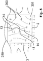
- Fig. 5 shows an estimate of the activation map as observed on the posterior wall of the left atrium.
- An activation map displays the time evolution of the cardiac depolarization, it shows the progression of the depolarization wave front over time 300, 301.
- the plot has the two axis z (ordinate) and x (abscissa), spanning a Cartesian coordinate system over the myocardium of the posterior wall of the left atrium (this area is hereby assumed to be flat 310). Then, z is the location 3 on this wall surface from distal to apical (bottom to top), x is the location 2 on this wall surface from left to right.
- the plot is a contour plot, where each line 300 indicates the course of the activation front at a given time relative to a single heart beat cycle; this time of each line is indicted as a number next to the line 301.
- the direction 18 of the arrow 15 indicates the direction of the depolarization wave front.
- the length, width or color of the arrow indicates the speed of the depolarization wave front.
Landscapes
- Health & Medical Sciences (AREA)
- Life Sciences & Earth Sciences (AREA)
- Cardiology (AREA)
- Heart & Thoracic Surgery (AREA)
- Molecular Biology (AREA)
- Pathology (AREA)
- Engineering & Computer Science (AREA)
- Biomedical Technology (AREA)
- Physics & Mathematics (AREA)
- Medical Informatics (AREA)
- Biophysics (AREA)
- Surgery (AREA)
- Animal Behavior & Ethology (AREA)
- General Health & Medical Sciences (AREA)
- Public Health (AREA)
- Veterinary Medicine (AREA)
- Pulmonology (AREA)
- Physiology (AREA)
- Measurement And Recording Of Electrical Phenomena And Electrical Characteristics Of The Living Body (AREA)
Applications Claiming Priority (1)
| Application Number | Priority Date | Filing Date | Title |
|---|---|---|---|
| EP17198175 | 2017-10-24 |
Publications (3)
| Publication Number | Publication Date |
|---|---|
| EP3476286A1 true EP3476286A1 (de) | 2019-05-01 |
| EP3476286C0 EP3476286C0 (de) | 2023-08-30 |
| EP3476286B1 EP3476286B1 (de) | 2023-08-30 |
Family
ID=60190615
Family Applications (1)
| Application Number | Title | Priority Date | Filing Date |
|---|---|---|---|
| EP18201568.5A Active EP3476286B1 (de) | 2017-10-24 | 2018-10-19 | Vorrichtung zur bereitstellung von elektrokardiographischen und insbesondere von arrhythmieinformationen |
Country Status (2)
| Country | Link |
|---|---|
| US (1) | US12016693B2 (de) |
| EP (1) | EP3476286B1 (de) |
Cited By (1)
| Publication number | Priority date | Publication date | Assignee | Title |
|---|---|---|---|---|
| EP4101384A1 (de) * | 2021-06-10 | 2022-12-14 | Biosense Webster (Israel) Ltd | Verfolgung von wellenausbreitung |
Families Citing this family (1)
| Publication number | Priority date | Publication date | Assignee | Title |
|---|---|---|---|---|
| US11331029B2 (en) * | 2016-11-16 | 2022-05-17 | Navix International Limited | Esophagus position detection by electrical mapping |
Citations (4)
| Publication number | Priority date | Publication date | Assignee | Title |
|---|---|---|---|---|
| US20090084382A1 (en) * | 2007-09-28 | 2009-04-02 | Fredrik Jalde | Catheter positioning method and computerized control unit for implementing the method |
| US20110066381A1 (en) * | 2009-09-11 | 2011-03-17 | Qualcomm Incorporated | Method and apparatus for artifacts mitigation with multiple wireless sensors |
| US20160270683A1 (en) | 2013-11-01 | 2016-09-22 | Koninklijke Philips N.V. | System for determining electrical characteristics on a surface of a heart |
| WO2017001912A1 (en) | 2015-07-02 | 2017-01-05 | Swissnovation Gmbh | System and method for providing a representation of cardiac cell charge state |
Family Cites Families (3)
| Publication number | Priority date | Publication date | Assignee | Title |
|---|---|---|---|---|
| US7123954B2 (en) * | 2002-09-19 | 2006-10-17 | Sanjiv Mathur Narayan | Method for classifying and localizing heart arrhythmias |
| EP1809174A4 (de) * | 2004-10-05 | 2008-04-23 | Cuoretech Pty Ltd | Herzanalyseverfahren und gerät |
| GB201706561D0 (en) * | 2017-04-25 | 2017-06-07 | Imp Innovations Ltd | Systems and methods for treating cardiac arrhythmia |
-
2018
- 2018-10-19 EP EP18201568.5A patent/EP3476286B1/de active Active
- 2018-10-24 US US16/169,154 patent/US12016693B2/en active Active
Patent Citations (4)
| Publication number | Priority date | Publication date | Assignee | Title |
|---|---|---|---|---|
| US20090084382A1 (en) * | 2007-09-28 | 2009-04-02 | Fredrik Jalde | Catheter positioning method and computerized control unit for implementing the method |
| US20110066381A1 (en) * | 2009-09-11 | 2011-03-17 | Qualcomm Incorporated | Method and apparatus for artifacts mitigation with multiple wireless sensors |
| US20160270683A1 (en) | 2013-11-01 | 2016-09-22 | Koninklijke Philips N.V. | System for determining electrical characteristics on a surface of a heart |
| WO2017001912A1 (en) | 2015-07-02 | 2017-01-05 | Swissnovation Gmbh | System and method for providing a representation of cardiac cell charge state |
Non-Patent Citations (7)
| Title |
|---|
| D. DONOHO: "Compressed Sensing", IEEE TRANSACTIONS ON INFORMATION THEORY, vol. 52, 2006, pages 1289 - 1306, XP055278657, DOI: doi:10.1109/TIT.2006.871582 |
| DE AMBROGGI; A. D. CORLAN: "Clinical use of body surface potential mapping in cardiac arrhythmias", ANADOLU KARDIYOLOJI DERGISI: AKD = THE ANATOLIAN JOURNAL OF CARDIOLOGY, vol. 7, no. 1, July 2007 (2007-07-01), pages 8 - 10 |
| E. J. CANDES; J. ROMBERG; T. TAO: "Stable signal recovery from incomplete and inaccurate measurements", COMM. PURE APPL. MATH., vol. 59, 2006, pages 1207 - 1223 |
| L. H. NAHUM; A. MAURO; H. M. CHERNOFF; R. S. SIKAND: "Instantaneous equipotential distribution on surface of the human body for various instants in the cardiac cycle", JOURNAL OF APPLIED PHYSIOLOGY, vol. 3, no. 8, 1951, pages 454 - 464 |
| N. ZALMAI; R. A. WILDHABER; D. CLAUSEN; H. A. LOELIGER: "Inferring depolarization of cells from 3D-electrode measurements using a bank of linear state space models", 2016 IEEE INTERNATIONAL CONFERENCE ON ACOUSTICS, SPEECH AND SIGNAL PROCESSING (ICASSP, 2016 |
| T MARISA ET AL: "Asynchronous ECG time sampling: Saving bits with Golomb-Rice encoding", COMPUTING IN CARDIOLOGY, 12 September 2012 (2012-09-12), pages 61 - 64, XP055467217, ISSN: 2325-8861, ISBN: 978-1-4799-0884-4 * |
| T. TAO; E. J. CANDES: "Near-optimal signal recovery from random projections: universal encoding strategies?", IEEE TRANSACTIONS ON INFORMATION THEORY, vol. 52, 2006, pages 5406 - 5425, XP011144183, DOI: doi:10.1109/TIT.2006.885507 |
Cited By (1)
| Publication number | Priority date | Publication date | Assignee | Title |
|---|---|---|---|---|
| EP4101384A1 (de) * | 2021-06-10 | 2022-12-14 | Biosense Webster (Israel) Ltd | Verfolgung von wellenausbreitung |
Also Published As
| Publication number | Publication date |
|---|---|
| EP3476286C0 (de) | 2023-08-30 |
| US12016693B2 (en) | 2024-06-25 |
| US20190117103A1 (en) | 2019-04-25 |
| EP3476286B1 (de) | 2023-08-30 |
Similar Documents
| Publication | Publication Date | Title |
|---|---|---|
| US20250017508A1 (en) | Cardiac analysis user interface system and method | |
| US11182911B2 (en) | Ultrasound-based geometry determination for electrophysiological mapping | |
| US9526434B2 (en) | Cardiac mapping with catheter shape information | |
| US7515954B2 (en) | Non-contact cardiac mapping, including moving catheter and multi-beat integration | |
| US7471973B2 (en) | Determining a surface geometry of an object | |
| US9675266B2 (en) | System and method for diagnosing arrhythmias and directing catheter therapies | |
| US7505810B2 (en) | Non-contact cardiac mapping, including preprocessing | |
| EP2712546A1 (de) | Kontaktfreies kardiales mapping mit beweglichem katheter und multiherzschlagintegration | |
| WO2014118535A2 (en) | Computerized system and method for fast cardiac mapping and ablation | |
| US9380940B2 (en) | Method and system for displaying a three dimensional visualization of cardiac motion | |
| CN108348186B (zh) | 用于标测心脏恢复的方法和系统 | |
| EP3476286B1 (de) | Vorrichtung zur bereitstellung von elektrokardiographischen und insbesondere von arrhythmieinformationen | |
| US20150313480A1 (en) | Method and system for calculating strain from characterization data of a cardiac chamber | |
| CN116342497B (zh) | 一种人体腔室内壁三维标测方法及系统 |
Legal Events
| Date | Code | Title | Description |
|---|---|---|---|
| PUAI | Public reference made under article 153(3) epc to a published international application that has entered the european phase |
Free format text: ORIGINAL CODE: 0009012 |
|
| STAA | Information on the status of an ep patent application or granted ep patent |
Free format text: STATUS: THE APPLICATION HAS BEEN PUBLISHED |
|
| AK | Designated contracting states |
Kind code of ref document: A1 Designated state(s): AL AT BE BG CH CY CZ DE DK EE ES FI FR GB GR HR HU IE IS IT LI LT LU LV MC MK MT NL NO PL PT RO RS SE SI SK SM TR |
|
| AX | Request for extension of the european patent |
Extension state: BA ME |
|
| STAA | Information on the status of an ep patent application or granted ep patent |
Free format text: STATUS: REQUEST FOR EXAMINATION WAS MADE |
|
| 17P | Request for examination filed |
Effective date: 20191018 |
|
| RBV | Designated contracting states (corrected) |
Designated state(s): AL AT BE BG CH CY CZ DE DK EE ES FI FR GB GR HR HU IE IS IT LI LT LU LV MC MK MT NL NO PL PT RO RS SE SI SK SM TR |
|
| STAA | Information on the status of an ep patent application or granted ep patent |
Free format text: STATUS: EXAMINATION IS IN PROGRESS |
|
| 17Q | First examination report despatched |
Effective date: 20220623 |
|
| REG | Reference to a national code |
Ref legal event code: R079 Ipc: A61B0005285000 Ref country code: DE Ref legal event code: R079 Ref document number: 602018056318 Country of ref document: DE Free format text: PREVIOUS MAIN CLASS: A61B0005042000 Ipc: A61B0005285000 |
|
| RIC1 | Information provided on ipc code assigned before grant |
Ipc: A61B 5/339 20210101ALI20230118BHEP Ipc: A61B 5/285 20210101AFI20230118BHEP |
|
| GRAP | Despatch of communication of intention to grant a patent |
Free format text: ORIGINAL CODE: EPIDOSNIGR1 |
|
| STAA | Information on the status of an ep patent application or granted ep patent |
Free format text: STATUS: GRANT OF PATENT IS INTENDED |
|
| INTG | Intention to grant announced |
Effective date: 20230315 |
|
| GRAS | Grant fee paid |
Free format text: ORIGINAL CODE: EPIDOSNIGR3 |
|
| GRAA | (expected) grant |
Free format text: ORIGINAL CODE: 0009210 |
|
| STAA | Information on the status of an ep patent application or granted ep patent |
Free format text: STATUS: THE PATENT HAS BEEN GRANTED |
|
| AK | Designated contracting states |
Kind code of ref document: B1 Designated state(s): AL AT BE BG CH CY CZ DE DK EE ES FI FR GB GR HR HU IE IS IT LI LT LU LV MC MK MT NL NO PL PT RO RS SE SI SK SM TR |
|
| REG | Reference to a national code |
Ref country code: GB Ref legal event code: FG4D |
|
| REG | Reference to a national code |
Ref country code: CH Ref legal event code: EP |
|
| REG | Reference to a national code |
Ref country code: DE Ref legal event code: R096 Ref document number: 602018056318 Country of ref document: DE |
|
| REG | Reference to a national code |
Ref country code: IE Ref legal event code: FG4D |
|
| U01 | Request for unitary effect filed |
Effective date: 20230830 |
|
| U07 | Unitary effect registered |
Designated state(s): AT BE BG DE DK EE FI FR IT LT LU LV MT NL PT SE SI Effective date: 20230905 |
|
| U20 | Renewal fee for the european patent with unitary effect paid |
Year of fee payment: 6 Effective date: 20231011 |
|
| PG25 | Lapsed in a contracting state [announced via postgrant information from national office to epo] |
Ref country code: GR Free format text: LAPSE BECAUSE OF FAILURE TO SUBMIT A TRANSLATION OF THE DESCRIPTION OR TO PAY THE FEE WITHIN THE PRESCRIBED TIME-LIMIT Effective date: 20231201 |
|
| PG25 | Lapsed in a contracting state [announced via postgrant information from national office to epo] |
Ref country code: IS Free format text: LAPSE BECAUSE OF FAILURE TO SUBMIT A TRANSLATION OF THE DESCRIPTION OR TO PAY THE FEE WITHIN THE PRESCRIBED TIME-LIMIT Effective date: 20231230 |
|
| PG25 | Lapsed in a contracting state [announced via postgrant information from national office to epo] |
Ref country code: RS Free format text: LAPSE BECAUSE OF FAILURE TO SUBMIT A TRANSLATION OF THE DESCRIPTION OR TO PAY THE FEE WITHIN THE PRESCRIBED TIME-LIMIT Effective date: 20230830 Ref country code: NO Free format text: LAPSE BECAUSE OF FAILURE TO SUBMIT A TRANSLATION OF THE DESCRIPTION OR TO PAY THE FEE WITHIN THE PRESCRIBED TIME-LIMIT Effective date: 20231130 Ref country code: IS Free format text: LAPSE BECAUSE OF FAILURE TO SUBMIT A TRANSLATION OF THE DESCRIPTION OR TO PAY THE FEE WITHIN THE PRESCRIBED TIME-LIMIT Effective date: 20231230 Ref country code: HR Free format text: LAPSE BECAUSE OF FAILURE TO SUBMIT A TRANSLATION OF THE DESCRIPTION OR TO PAY THE FEE WITHIN THE PRESCRIBED TIME-LIMIT Effective date: 20230830 Ref country code: GR Free format text: LAPSE BECAUSE OF FAILURE TO SUBMIT A TRANSLATION OF THE DESCRIPTION OR TO PAY THE FEE WITHIN THE PRESCRIBED TIME-LIMIT Effective date: 20231201 |
|
| PG25 | Lapsed in a contracting state [announced via postgrant information from national office to epo] |
Ref country code: PL Free format text: LAPSE BECAUSE OF FAILURE TO SUBMIT A TRANSLATION OF THE DESCRIPTION OR TO PAY THE FEE WITHIN THE PRESCRIBED TIME-LIMIT Effective date: 20230830 |
|
| PG25 | Lapsed in a contracting state [announced via postgrant information from national office to epo] |
Ref country code: ES Free format text: LAPSE BECAUSE OF FAILURE TO SUBMIT A TRANSLATION OF THE DESCRIPTION OR TO PAY THE FEE WITHIN THE PRESCRIBED TIME-LIMIT Effective date: 20230830 |
|
| PG25 | Lapsed in a contracting state [announced via postgrant information from national office to epo] |
Ref country code: SM Free format text: LAPSE BECAUSE OF FAILURE TO SUBMIT A TRANSLATION OF THE DESCRIPTION OR TO PAY THE FEE WITHIN THE PRESCRIBED TIME-LIMIT Effective date: 20230830 Ref country code: RO Free format text: LAPSE BECAUSE OF FAILURE TO SUBMIT A TRANSLATION OF THE DESCRIPTION OR TO PAY THE FEE WITHIN THE PRESCRIBED TIME-LIMIT Effective date: 20230830 Ref country code: ES Free format text: LAPSE BECAUSE OF FAILURE TO SUBMIT A TRANSLATION OF THE DESCRIPTION OR TO PAY THE FEE WITHIN THE PRESCRIBED TIME-LIMIT Effective date: 20230830 Ref country code: CZ Free format text: LAPSE BECAUSE OF FAILURE TO SUBMIT A TRANSLATION OF THE DESCRIPTION OR TO PAY THE FEE WITHIN THE PRESCRIBED TIME-LIMIT Effective date: 20230830 Ref country code: SK Free format text: LAPSE BECAUSE OF FAILURE TO SUBMIT A TRANSLATION OF THE DESCRIPTION OR TO PAY THE FEE WITHIN THE PRESCRIBED TIME-LIMIT Effective date: 20230830 |
|
| PG25 | Lapsed in a contracting state [announced via postgrant information from national office to epo] |
Ref country code: MC Free format text: LAPSE BECAUSE OF FAILURE TO SUBMIT A TRANSLATION OF THE DESCRIPTION OR TO PAY THE FEE WITHIN THE PRESCRIBED TIME-LIMIT Effective date: 20230830 |
|
| REG | Reference to a national code |
Ref country code: DE Ref legal event code: R097 Ref document number: 602018056318 Country of ref document: DE |
|
| PLBE | No opposition filed within time limit |
Free format text: ORIGINAL CODE: 0009261 |
|
| STAA | Information on the status of an ep patent application or granted ep patent |
Free format text: STATUS: NO OPPOSITION FILED WITHIN TIME LIMIT |
|
| 26N | No opposition filed |
Effective date: 20240603 |
|
| PG25 | Lapsed in a contracting state [announced via postgrant information from national office to epo] |
Ref country code: IE Free format text: LAPSE BECAUSE OF NON-PAYMENT OF DUE FEES Effective date: 20231019 |
|
| PG25 | Lapsed in a contracting state [announced via postgrant information from national office to epo] |
Ref country code: IE Free format text: LAPSE BECAUSE OF NON-PAYMENT OF DUE FEES Effective date: 20231019 |
|
| U20 | Renewal fee for the european patent with unitary effect paid |
Year of fee payment: 7 Effective date: 20241011 |
|
| PG25 | Lapsed in a contracting state [announced via postgrant information from national office to epo] |
Ref country code: CY Free format text: LAPSE BECAUSE OF FAILURE TO SUBMIT A TRANSLATION OF THE DESCRIPTION OR TO PAY THE FEE WITHIN THE PRESCRIBED TIME-LIMIT; INVALID AB INITIO Effective date: 20181019 |
|
| PG25 | Lapsed in a contracting state [announced via postgrant information from national office to epo] |
Ref country code: HU Free format text: LAPSE BECAUSE OF FAILURE TO SUBMIT A TRANSLATION OF THE DESCRIPTION OR TO PAY THE FEE WITHIN THE PRESCRIBED TIME-LIMIT; INVALID AB INITIO Effective date: 20181019 |
|
| REG | Reference to a national code |
Ref country code: CH Ref legal event code: U11 Free format text: ST27 STATUS EVENT CODE: U-0-0-U10-U11 (AS PROVIDED BY THE NATIONAL OFFICE) Effective date: 20251101 |
|
| U20 | Renewal fee for the european patent with unitary effect paid |
Year of fee payment: 8 Effective date: 20251013 |
|
| U1N | Appointed representative for the unitary patent procedure changed after the registration of the unitary effect |
Representative=s name: PITICCO, LORENA; CH |
|
| PG25 | Lapsed in a contracting state [announced via postgrant information from national office to epo] |
Ref country code: TR Free format text: LAPSE BECAUSE OF FAILURE TO SUBMIT A TRANSLATION OF THE DESCRIPTION OR TO PAY THE FEE WITHIN THE PRESCRIBED TIME-LIMIT Effective date: 20230830 |
|
| PGFP | Annual fee paid to national office [announced via postgrant information from national office to epo] |
Ref country code: GB Payment date: 20251022 Year of fee payment: 8 |
|
| PGFP | Annual fee paid to national office [announced via postgrant information from national office to epo] |
Ref country code: CH Payment date: 20251101 Year of fee payment: 8 |