EP3476314A1 - Procédé de mise en place d'une ligature pour serrer automatiquement une ligne élastique. - Google Patents
Procédé de mise en place d'une ligature pour serrer automatiquement une ligne élastique. Download PDFInfo
- Publication number
- EP3476314A1 EP3476314A1 EP17819142.5A EP17819142A EP3476314A1 EP 3476314 A1 EP3476314 A1 EP 3476314A1 EP 17819142 A EP17819142 A EP 17819142A EP 3476314 A1 EP3476314 A1 EP 3476314A1
- Authority
- EP
- European Patent Office
- Prior art keywords
- elastic line
- line
- elastic
- ligator
- tightening
- Prior art date
- Legal status (The legal status is an assumption and is not a legal conclusion. Google has not performed a legal analysis and makes no representation as to the accuracy of the status listed.)
- Granted
Links
Images


Classifications
-
- A—HUMAN NECESSITIES
- A61—MEDICAL OR VETERINARY SCIENCE; HYGIENE
- A61B—DIAGNOSIS; SURGERY; IDENTIFICATION
- A61B17/00—Surgical instruments, devices or methods
- A61B17/12—Surgical instruments, devices or methods for ligaturing or otherwise compressing tubular parts of the body, e.g. blood vessels or umbilical cord
- A61B17/12009—Implements for ligaturing other than by clamps or clips, e.g. using a loop with a slip knot
-
- A—HUMAN NECESSITIES
- A61—MEDICAL OR VETERINARY SCIENCE; HYGIENE
- A61B—DIAGNOSIS; SURGERY; IDENTIFICATION
- A61B17/00—Surgical instruments, devices or methods
- A61B17/32—Surgical cutting instruments
- A61B17/3205—Excision instruments
- A61B17/32056—Surgical snare instruments
-
- A—HUMAN NECESSITIES
- A61—MEDICAL OR VETERINARY SCIENCE; HYGIENE
- A61B—DIAGNOSIS; SURGERY; IDENTIFICATION
- A61B17/00—Surgical instruments, devices or methods
- A61B2017/00831—Material properties
- A61B2017/00862—Material properties elastic or resilient
-
- A—HUMAN NECESSITIES
- A61—MEDICAL OR VETERINARY SCIENCE; HYGIENE
- A61B—DIAGNOSIS; SURGERY; IDENTIFICATION
- A61B17/00—Surgical instruments, devices or methods
- A61B17/04—Surgical instruments, devices or methods for suturing wounds; Holders or packages for needles or suture materials
- A61B17/06—Needles ; Sutures; Needle-suture combinations; Holders or packages for needles or suture materials
- A61B17/06166—Sutures
- A61B2017/0618—Sutures elastic, e.g. stretchable
-
- A—HUMAN NECESSITIES
- A61—MEDICAL OR VETERINARY SCIENCE; HYGIENE
- A61B—DIAGNOSIS; SURGERY; IDENTIFICATION
- A61B17/00—Surgical instruments, devices or methods
- A61B17/12—Surgical instruments, devices or methods for ligaturing or otherwise compressing tubular parts of the body, e.g. blood vessels or umbilical cord
- A61B17/12009—Implements for ligaturing other than by clamps or clips, e.g. using a loop with a slip knot
- A61B2017/12018—Elastic band ligators
-
- A—HUMAN NECESSITIES
- A61—MEDICAL OR VETERINARY SCIENCE; HYGIENE
- A61B—DIAGNOSIS; SURGERY; IDENTIFICATION
- A61B90/00—Instruments, implements or accessories specially adapted for surgery or diagnosis and not covered by any of the groups A61B1/00 - A61B50/00, e.g. for luxation treatment or for protecting wound edges
- A61B90/03—Automatic limiting or abutting means, e.g. for safety
Definitions
- the present disclosure relates to medical instruments, particularly to a ligator setup method for automatically tightening elastic line and a self-tightening elastic line ligator.
- Hemorrhoid ligation also known as hemorrhoid apron ligation, hemorrhoid suction ligation, etc. is a common method for treatment of hemorrhoid and has exact curative effect.
- the principle of the hemorrhoid ligation is ligating a special apron (e.g., rubber ring, latex ring, silicone ring, elastic line ring, etc.) to the root (or bottom) of the internal hemorrhoid to block the blood supply of the hemorrhoid by the elastic retraction force of the apron, thereby causing the hemorrhoid to become necrotic, atrophy and shedding, and achieving the purpose of healing.
- apron e.g., rubber ring, latex ring, silicone ring, elastic line ring, etc.
- the hemorrhoid ligators are currently available in two categories: A: Apron hemorrhoid ligator B: Elastic line hemorrhoid ligator.
- the apron hemorrhoid suction ligator also known as hemorrhoid ligator
- hemorrhoid ligator and other types of hemorrhoid ligator at home and abroad have a common feature that they all use "aprons" as the basic material for ligation of the root of the hemorrhoid, while the materials used to make the apron may include natural rubber, latex or silicone, etc.
- the clinical efficacy of the hemorrhoid apron ligation is directly related to two technical indicators of "inner diameter of the apron" and "elastic retraction force of the apron".
- the use of aprons as a ligation material has some inherent disadvantages that: 1 due to the inherent properties of the natural rubber (or the latex, the silicone, etc.), the inner diameter of the apron cannot be infinitely small, and generally can only be 2.0 ⁇ 2.5 mm (at least not less than 1.5 mm), otherwise it will be very easy to be broken during the ligation, which means that, in the size range of 2.0 ⁇ 2.5 mm (at least not less than 1.5 mm) in diameter, the ligated hemorrhoid tissue will not be subjected to any elastic retraction force, and the ulceration formed after the tissue necrosis is also about 2.0 ⁇ 2.5 mm (at least not less than 1.5 mm); 2 when the apron is installed to the ligator in a stretched state, it
- Manual elastic line hemorrhoid suction ligator can overcome the shortcoming of the apron ligator that the apron cannot be tight, but the process of fastening the target tissue is complicated, the positioning and pop-up of the push line require many operation flows, and the use is not convenient.
- the only way is releasing the ligation tissue from the emitting end first, thereafter releasing the push tube, and then manually tightening the elastic line loop of the push tube to ligate the hemorrhoid tissue (or other target tissue). During this operation, the elastic line loop is easy to slip off the tissue, thereby affecting the treatment effect.
- the present disclosure provides a ligator setup method for automatically tightening elastic line.
- the method includes disposing at least one elastic line along an outer wall of an outer barrel of the ligator.
- a front end of the elastic line forms a size-adjustable loop loopingly disposed on an outer wall of a front end of an inner barrel.
- a distal end of the elastic line is connected with a line-retracting auto-connector of the ligator, and the other end of the line-retracting auto-connector is connected with a self-tightening trigger via a telescopic spring.
- the self-tightening trigger releases the abutment to the telescopic spring and the line-retracting auto-connector tightens backward the elastic line under an action of a resilient force off the telescopic spring, thereby rapidly reducing a size of the loop at the front end of the elastic line.
- a self-tightening elastic line ligator includes a body and a barrel.
- the barrel includes an inner barrel and an outer barrel, and at least one elastic line.
- the elastic line is disposed along an outer wall of the outer barrel of the ligator.
- a front end of the elastic line form a size-adjustable loop loopingly disposed on an outer wall of a front end of the inner barrel.
- a distal end of the elastic line is connected with a line-retracting auto-connector of the ligator, and the other end of the line-retracting auto-connector is connected with a self-tightening trigger via a telescopic spring.
- the self-tightening trigger releases an abutment to the telescopic spring and the line-retracting auto-connector tightens backward the elastic line under an action of a resilient force off the telescopic spring, thereby rapidly reducing a size of the loop at the front end of the elastic line.
- the present disclosure provides a ligator setup method for automatically tightening elastic line and a self-tightening elastic line ligator. They provide the backward tightening resilient elastic force for the line-retracting auto-connector by the telescopic spring and automatically tighten the elastic line.
- the doctor only needs to press the self-tightening trigger to make the self-tightening trigger release the abutment to the telescopic spring, and then the line-retracting auto-connector can tighten backward the elastic line under the action of the resilient force of the telescopic spring, thereby rapidly reducing the size of the loop at the front end of the elastic line to minimum and close to zero, and achieving more tight ligation of the target tissue.
- the elastic line has good elastic contractility
- the loop of the elastic line is also reduced during the process of gradually necrosis and detachment of the target tissue, until the target tissue is necrotic and detached.
- the ulcer surface formed thereby is extremely small, and the chance of postoperative bleeding is reduced.
- the ligator setup methods for automatically tightening elastic line and the self-tightening elastic line ligators of the present disclosure have the advantages of simple structure, convenient operation and wide application.
- the present disclosure may provide a ligator setup method for automatically tightening elastic line.
- the method may include disposing at least one elastic line 30 along an outer wall of an outer barrel 22 of the ligator.
- a front end of the elastic line 30 may form a size-adjustable loop loopingly disposed on an outer wall of a front end of an inner barrel 21.
- a distal end of the elastic line 30 may be connected to a line-retracting auto-connector 80 of the ligator.
- the other end of the line-retracting auto-connector 80 may be connected, via a telescopic spring 90, to a self-tightening trigger 100.
- the elastic line 30 is in a stretched state.
- the self-tightening trigger 100 loosens the abutment thereof to the telescopic spring, and the line-retracting auto-connector 80 tightens backward the elastic line 30 under an action of a resilient force of the telescopic spring, thereby rapidly reducing the size of the loop at the front end of the elastic line 30.
- the elastic line 30 may form the loop by a pirate knot which only allows the elastic line 20 to be pulled in one direction.
- the outer barrel 22 of the ligator is able to be moved with respect to the inner barrel 21 or the inner barrel 21 is able to be moved with respect to the outer barrel 22.
- the inner diameter of the outer barrel 22 matches the outer diameter of the inner barrel 21.
- the nozzle of the inner barrel 21 protrudes from the nozzle of the outer barrel 22.
- the wall of the outer barrel 22 push the elastic line 30 out of a barrel body of the inner barrel 21.
- the retraction stroke of the line-retracting auto-connector 80 is set to be greater than the maximum tension length of the elastic line 30. Therefore, the power pulling end can stretch the elastic line 30 to the maximum tension length such that the diameter of the loop at the front of the elastic line 30 is reduced to a minimum diameter and close to zero, thereby achieving a more tight ligation of the target tissue. Furthermore, since the elastic line 30 has good elastic contractility, the loop of the elastic line 30 is also reduced during the process of gradually necrosis and detachment of the target tissue, until the target tissue is necrotic and detached. The ulcer surface formed thereby is extremely small, and the chance of postoperative bleeding is reduced.
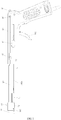
- a self-tightening elastic line ligator using the setup methods of elastic line 30 above, as shown in FIG. 1 and FIG. 2 include a body 10 and a barrel 20.
- the barrel 20 includes an inner barrel 21, an outer barrel 22 and at least one elastic line 30.
- the elastic line 30 is disposed along an outer wall of the outer barrel 22 of the ligator.
- a front end of the elastic line 30 forms a size-adjustable loop loopingly disposed on an outer wall of a front end of the inner barrel 21.
- a distal end of the elastic line 30 is connected with a line-retracting auto-connector 80 of the ligator.
- the other end of the line-retracting auto-connector 80 is connected with a self-tightening trigger 100 via a telescopic spring.
- the self-tightening trigger 100 loosens the connection thereof to the telescopic spring, and the line-retracting auto-connector 80 tightens backward the elastic line 30 by means of a recoiling force of the telescopic spring, thereby rapidly reducing the size of the loop at the front end of the elastic line 30.
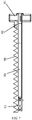
- the elastic line 30 includes inner and outer layers.
- the inner layer (elastic strip) is a strip-shaped special polymer material with high elasticity.
- the outer layer (wrapped layer) is a mesh braided layer, wrapped on the surface of the inner layer, also made of special polymer materials, and able to stretch with the stretching of the elastic strip of the inner layer.
- the special double-layer structure of the elastic line 30 not only has good elasticity, but also can withstand strong axial pulling force without breaking. When the elastic line loop in stretched state is sleeved on the target tissue, it can be further tightened due to its own elasticity to reduce its size. Furthermore, the elastic line 30 is not easy to age and fatigue when it is in a non-stretched state, therefore it has a long service life, and the ligation effect can be improved.
- An inner tube 11 is disposed in the body 10. A front end of the inner tube 11 is communicated with the inner barrel 21, and the distal end of the inner tube 11 is communicated with a negative pressure air pipe, i.e., the inner barrel 21 is under negative pressure in working condition and adsorbs and retracts the target tissue.
- An elastic line bayonet 221 is provided at the location where the elastic line 30 is buckled on the outer barrel 22. The distal end of the elastic line 30 passes through the elastic line bayonet 221 to connect with the line-retracting auto-connector 80 of the ligator. The elastic line bayonet 221 abuts against the pirate knot of the loop.
- the outer barrel 22 When the target tissue is absorbed and lifted up, the outer barrel 22 is moved with respect to the inner barrel 21 or the inner barrel 21 is moved with respect to the outer barrel 22, the wall of the outer barrel 22 pushes the elastic line loop out of the inner barrel 21 such that the elastic line 30 is detached from the barrel 20 and ligates the target tissue absorbed into the inner barrel 21.
- relative displacement occurs between the elastic line bayonet 221 and the elastic line loop, and the elastic line bayonet 221 also pushes the elastic line 30 out of the inner barrel 21, such that the elastic line 30 is detached from the barrel 20.
- the elastic line bayonet 221 can abut against the pirate knot, thereby preventing the loop from slipping off the target tissue.
- the relative displacement of the inner barrel with respect to the outer barrel is controlled by a misalignment mechanism.
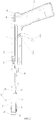
- the misalignment mechanism is disposed at the rear end of the body, as shown in FIG. 2 , and includes a reset button 40 and a misalignment button 50.
- the reset button 40 is coaxially connected with the distal end of the inner tube 11 of the body, and a lateral elastic member 41 for providing a resilient elastic force is provided between the reset button 40 and the body 10.
- the lateral elastic member 41 provides the reset button 40 with a resilient force for backward movement.
- the reset button 40 is provided with a limiting hole 42.
- the misalignment button 50 longitudinally passes through the limiting hole 42 and is connected with the body 10 via a longitudinal elastic member 51 (not shown in the figures).
- the body of the misalignment button 50 is provided with a limiting shaft 52 which has a diameter matching the diameter of the limiting hole 42.
- the diameter of the limiting hole 42 is greater than the diameter of the body of the misalignment button 50.
- the inner tube 11 is provided with a first elastic snap end 411 and the body 10 is provided with a second elastic snap end 412.
- the lateral elastic member 41 is disposed between the first elastic snap end 411 and the second elastic snap end 412, and the distance between the first elastic snap end 411 and the second elastic snap end 412 is greater than the free state length of the second elastic member. Therefore, the second elastic member is in an expanded state, which provides a resilient force for the relative movement between the inner tube 11 and the body 10 and, in the case that the body 10 keeps stationary, provides a resilient force for the backward movement of the reset button 40.
- the limiting hole 42 includes a first limiting hole 421 and a second limiting hole 422 which are communicated with each other.
- the diameter of the first limiting hole 421 is greater than the diameter of the second limiting hole 422, and in the lateral direction of the body 10, the second limiting hole 422 is located at front of the first limiting hole 421.
- the limiting shaft 52 includes a first limiting shaft 521 and a second limiting shaft 522.
- the diameters of the first limiting shaft 521 and the second limiting shaft 522 match the diameters of the first limiting hole 521 and the second limiting hole 422, respectively.
- the first limiting shaft 521 is located at inner side of the second limiting shaft 522.
- the misalignment button 50 When the misalignment button 50 is longitudinally moved into the body 10, the first limiting shaft 521 and the first limiting hole 421 are longitudinally misaligned. Under the action of the resilient force of the second elastic member, the second limiting shaft 522 abuts against the second limiting hole 422. At the same time, the inner tube 11 brings the inner barrel 21 to move backward with respect to the outer barrel 22. The elastic line loop sleeved on the front end of the inner barrel 21 is slid off from the inner barrel 21 under the braking of the elastic line bayonet 221 to realize the ligation of the target tissue.
- the second limiting shaft 522 and the second limiting hole 422 are laterally misaligned.
- the first limiting shaft 521 is longitudinally moved outward to abut against the first limiting hole 521.
- the inner tube 11 is moved forward with respect to the body 10 to the initial position so as to perform the next installation of the barrel 20.
- the automatic tensioning mechanism for the elastic line 30 disposed on the ligator tightens backward the elastic line 30 such that the size of the loop at the front end of the elastic line 30 is rapidly reduced.
- the automatic tensioning mechanism for the elastic line 30 includes the line-retracting auto-connector 80 passing through the elastic line bayonet 221 and connecting with the distal end of the elastic line 30; the telescopic spring 90 of which one end abuts the body 10 and the other end abuts the line-retracting auto-connector 80; the self-tightening trigger 100 abutting the free end of the line-retracting auto-connector 80.
- the line-retracting auto-connector 80 is rebounded backward by the telescopic spring 90 and causes the size of the loop at the front end of the elastic line to be rapidly reduced.
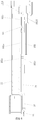
- a tension stroke groove 101 is arranged in the body 10 of the ligator.
- the line-retracting auto-connector 80 is disposed in the tension stroke groove 101.
- the distal end of the elastic line 30 passes through a through hole provided in an elastic line stroke groove 102 along the outer wall of the outer barrel 22 and connects with the line-retracting auto-connector 80.
- a spring groove parallel to the tension stroke groove 101 is arranged at one side of the tension stroke groove 101.
- the telescopic spring 90 is arranged in the spring groove, as shown in FIG. 7 .
- a column 82 is laterally extended from the free end 81 of the line-retracting auto-connector 80.
- One end of the telescopic spring 90 is abutted against the spring groove, and the other end is sleeved on the column 82.
- the self-tightening trigger 100 is disposed below the tension stroke groove 101.
- a rotation return spring is disposed on the fulcrum 100a, and provides counterclockwise resilient force for the self-tightening trigger 100.
- the self-tightening trigger 100 is communicated with the tension stroke groove 101 via a through groove 101a.
- the self-tightening trigger 100 is popped counterclockwise to abut the free end 81 of the line-retracting auto-connector 80.
- the line-retracting auto-connector 80 When pressing the self-tightening trigger 100 clockwise to release the limitation to the line-retracting auto-connector 80, the line-retracting auto-connector 80 is rebounded backward under the action of the resilient force of the telescopic spring 90 and pulls the loop at the front end of the elastic line to reduce rapidly the size thereof.
- the retraction stroke of the line-retracting auto-connector 80 is greater than the maximum tension length of the elastic line 30. Therefore, the line-retracting auto-connector 80 can stretch the elastic line to the maximum tension length such that the size of the loop at the front end of the elastic line 30 is reduced to minimum and close to zero, thereby achieving more tight ligation of the target tissue.
- the free end 81 of the line-retracting auto-connector 80 protrudes longitudinally out of the tension stroke groove 101 from the two sides of the body 10 and forms the manual self-tightening button 84 by extension.
- the manual self-tightening button 84 is provided with a friction surface. Since the retraction stroke of the line-retracting auto-connector 80 is greater than the maximum tension length of the elastic line 30, when the telescopic spring 90 returns to the extended state there is still a stretchable distance between the free end 81 of the line-retracting auto-connector 80 and the end of the tension stroke groove 101.
- the self-tightening button 84 is manually pulled back such that the size of the loop at the front end of the elastic line 30 continues to be reduced to the minimum size and close to zero.
- An elastic line connection end 31 is arranged at the distal end of the elastic line 30.
- the outer wall of the outer barrel 22 of the ligator is provided with an elastic line stroke groove 102 which is connected and communicated with the tension stroke groove 101.
- the elastic line connection end 31 is disposed in the elastic line stroke groove 102.
- the elastic line connection end 31 passes through the through hole disposed in the elastic line stroke groove 102 and is tied on the distal end of the elastic line 30.
- the elastic line connection end 31 includes a connection end front portion 301 and a connection end rear portion 302. As shown in FIG. 8 and FIG.
- connection end guide grooves 102a whose lengths are corresponded to the length of the elastic line stroke groove 102 are disposed on both groove walls of the elastic line stroke groove 102.
- guide sliding wings 311 are longitudinally extended from both sides of the connection end rear portion 302. The guide sliding wings 311 are sleeved in the connection end guide groove 102a so as to ensure that the elastic line connection end 31 maintains a horizontal linear motion.
- connection end front portion 301 passes through the through hole disposed in the elastic line stroke groove 102 and extends to the elastic line bayonet 221 along the outer wall of the outer barrel 22, and connects with the distal end of the elastic line 30 passing through the elastic line bayonet 221, so as to shorten the elastic tension length of the elastic line 30 as much as possible, thereby minimizing the tensile loss of the line-retracting auto-connector 80 to the elastic line loop.
- connection end front portion 301 of the elastic line connection end 31 is provided, successively along the extension direction of the body, with a first groove 312 and a second groove 314 in which a compression spring 316 is arranged.
- the first groove 312 is sleeved by a sleeve 32 with a pulling cord 321.
- the distal end of the elastic line 30 is provided with a knot. The knot is pressed in the first groove 312 by the sleeve 32.
- connection end guide grooves 102a are communication grooves between the elastic line stroke groove 102 and the outer wall of the outer barrel 22.
- the body of the elastic line connection end 31 is provided with a pull guide channel 315.
- the pull guide channel 315 extends along the body of the elastic line connection end 31 from the second groove 314 to the guide sliding wings 311 of the connection end rear portion 302.
- the other end of the pulling cord 321 passes through the connection end guide groove 102a along the pull guide channel 315 and connects with a pulling member 322.
- the pulling member 322 abuts against the guide sliding wings 311.
- the rear portion of the sleeve 32 is connected with the compression spring 316 in the second groove 314.
- the compression spring 316 presses the sleeve 32 forward so as to prevent the sleeve 32 from accidentally falling off in non-normal use.
- the sleeve 32 is moved backward by pulling the pulling member 322, such that the knot at the distal end of the elastic line 30 is disengaged from the first groove 312, thereby achieving the unloading of the elastic line 30.
- a power pulling end 83 is disposed at one end of the line-retracting auto-connector 80 where it is connected with the elastic line 30.
- the tension stroke end of the power pulling end 83 corresponds to the front end of the elastic line stroke groove 102
- the retraction stroke end of the power pulling end 83 corresponds to the distal end of the elastic line stroke groove 102.
- the power pulling end 83 is provided with a snap opening 831 having a certain tension.
- the upper and lower ends of the snap opening 831 are oppositely protruded and provided with snap points 832.
- the snap points 832 abut against each other.
- the connection end rear portion 302 of the elastic line connection end 31 is provided with a second holes 313 for engaging with the snap points 832.
- the power pulling end 83 makes the elastic line connection end 31 to abut against the tension stroke end of the power pulling end 83, as shown in FIG. 9 , the snap opening 831 of the power pulling end 83 is opened by the elastic connection end, and the snap points 832 are snapped into the second hole 313.
- the power pulling end 83 is snap-connected with the elastic line connection 31. I.e., when the manual self-tightening button 84 is pulled to the minimum retraction stroke end of the telescopic spring 90, the line-retracting auto-connector 80 enters into the elastic line stroke groove 102.
- the power pulling end 83 makes the elastic line connection end 31 to abut to the tension stroke end and snap-connects the elastic line connection end 31.
- an expansion point 102b is disposed at the retraction stoke end of the power pulling end 83, i.e. the distal end of the elastic line stroke groove 102 is provided with an expansion point 102b, which expands the power pulling end 83 when the power pulling end 83 is pulled backward to the retraction stroke end to disengage the elastic line connection end 31 from the power pulling end 83.
- the expansion point 102b is wedge-shaped, and the width of the expansion point 102b gradually increases along the retraction direction of the power pulling end 83, such that the upper and lower snap points 832 of the power pulling end 83 are outwardly extended and disengaged from the second holes 313 of the elastic line connection end 31.
- the longitudinal width of the top end and distal end of the elastic line stroke groove 102 is greater than the longitudinal width of the groove body of the elastic line stroke groove 102.
- the front end of the elastic line stroke groove 102 is provided with upper and lower free notches 102c.
- the lower groove wall at the distal end of the elastic line stroke groove 102 is recessed downwardly to form an expansion groove 102d, and the upper groove wall is provided with an expansion opening 102e.
- the top end of the elastic line stroke groove 102 corresponds to the tension stroke end of the power pulling end 83
- the distal end of the elastic line stroke groove 102 corresponds to the retraction stroke end of the power pulling end 83.
- the power pulling end 83 has a longitudinal free width at the tension stroke end and the retraction stroke end.
- the power pulling end 83 when the power pulling end 83 makes the elastic line connection end 31 to abut against the tension stroke end, the power pulling end 83 will not be limited by the longitudinal width of the elastic line stroke groove 102, and the snap opening 831 is longitudinally opened by the elastic connection end such that the snap points 832 are oppositely snapped into the second holes 313, thereby achieving the snap-connection of the power pulling end 83 with the elastic line connection end 31.
- the power pulling end 83 When the power pulling end 83 is pulled backward to the retraction stroke end, the power pulling end 83 will not be limited by the longitudinal width of the elastic line stroke groove 102, and the snap opening 831 is expanded by the expansion point 102b, such that the elastic line connection end 31 disengages from the power pulling end 83.
- the barrel 20 is connected with the body 10 by a snap structure 60.
- the snap structure 60 includes an inner buckle member 61 disposed at the rear end of the inner barrel 21 and an unbuckling member 62 disposed on the inner tube 11.
- the inner tube 11 is provided with a snap groove 611 cooperating with the inner buckle member 61, and the unbuckling member 62 is arranged relative to the snap groove 611.
- a sealing ring 63 is arranged on the port at the distal end of the inner barrel 21 where it is connected with the inner tube 11, which is used for sealing the gap between the inner barrel 21 and the inner tube 11.
- the inner buckle member 61 When the inner barrel 21 is snap-connected with the inner tube 11, the inner buckle member 61 is snapped in the snap groove 611, and the sealing ring 63 seals the gap between the communication ports of the inner barrel 21 and the inner tube 11 so as to ensure the negative pressure index in the inner barrel 21.
- the unbuckling member 62 When a new barrel 20 needs to be replaced, the unbuckling member 62 is pressed inwardly to push the inner buckle member 61 out of the snap groove 611 to untie the snap connection between the inner barrel 21 and the inner tube 11, thereby achieving the separation of the barrel 20 with the body 10 and facilitating the installation of the new barrel 20.
- the outer wall of the outer barrel 22 is also provided with a snap member, and the body 10 is provided with a bayonet groove which cooperates with the snap member. The outer barrel 22 is buckled to the body 10 by the snap member.
- the barrel 20 whose elastic line 30 is used may be detached from the body 10 and the manual self-tightening button 84 is pulled to the minimum retraction stroke end of the telescopic spring 90.
- the self-tightening trigger 100 is popped counterclockwise to abut the line-retracting auto-connector 80.
- a new barrel 2o equipped with a new elastic line 30 is snapped on the body 10 by the snap structure 60 and the snap member.
- the power pulling end 83 abuts the elastic line connection end 31 to the tension stroke end and snap-connects the connection end of the elastic line 30, thereby completing the installation of the new barrel 20. Then, the ligation operation above can be restarted.
- an outer wall of the inner barrel 21 is provided with a limiting block 70, and an inner wall of the outer barrel 22 is recessed relatively to the limiting block 70 to form a limiting groove 71.
- the limiting groove 71 has a groove body extending along the length direction of the body 10.
- the limiting block 70 abuts in the limiting groove 71. Therefore, the inner barrel 21 is able to move with respect to the outer barrel 22 in the length direction, but maintains a fixed relative positional relationship with the outer barrel 22 in the axial direction.
- the nozzle of the ligator is provided with a limiting cap 72.
- the limiting cap 72 is sleeved on the outer wall of the inner barrel 21 and presses the elastic line loop on the outer wall of the inner barrel 21. Further, the nozzle diameters of the outer barrel 22 and the inner barrel 21 are both greater than the diameter of the barrel body.
- a misalignment space is arranged between the nozzle of the outer barrel 22 and the nozzle of the inner barrel 21.
- a limiting bolt 73 is disposed in the misalignment space. The limiting bolt 73 passes through the wall of the outer barrel 22 and abuts the wall of the inner barrel 21. The limiting cap 72 and the limiting bolt 73 are used to ensure that the loop will not fall off the inner barrel 21 when not in use.
- the present disclosure provides a ligator setup method for automatically tightening elastic line and a self-tightening elastic line ligator. They provide the backward tightening resilient elastic force for the line-retracting auto-connector 80 by the telescopic spring 90 and automatically tighten the elastic line 30.
- the doctor only needs to press the self-tightening trigger 100 to make the self-tightening trigger 100 release the abutment to the telescopic spring 90, and then the line-retracting auto-connector 80 can tighten backward the elastic line 30 under the action of the resilient force of the telescopic spring 90, thereby rapidly reducing the size of the loop at the front end of the elastic line 30 to minimum and close to zero, and achieving more tight ligation of the target tissue.
- the elastic line 30 has good elastic contractility, the loop of the elastic line 30 is also reduced during the process of gradually necrosis and detachment of the target tissue, until the target tissue is necrotic and detached.
- the ulcer surface formed thereby is extremely small, and the chance of postoperative bleeding is reduced.
- the ligator setup methods for automatically tightening elastic line and the self-tightening elastic line ligators of the present disclosure have the advantages of simple structure, convenient operation and wide application.
Landscapes
- Health & Medical Sciences (AREA)
- Life Sciences & Earth Sciences (AREA)
- Surgery (AREA)
- Molecular Biology (AREA)
- Engineering & Computer Science (AREA)
- Biomedical Technology (AREA)
- Heart & Thoracic Surgery (AREA)
- Medical Informatics (AREA)
- Nuclear Medicine, Radiotherapy & Molecular Imaging (AREA)
- Animal Behavior & Ethology (AREA)
- General Health & Medical Sciences (AREA)
- Public Health (AREA)
- Veterinary Medicine (AREA)
- Reproductive Health (AREA)
- Vascular Medicine (AREA)
- Surgical Instruments (AREA)
Applications Claiming Priority (4)
| Application Number | Priority Date | Filing Date | Title |
|---|---|---|---|
| CN201610493124.7A CN105997182B (zh) | 2016-06-28 | 2016-06-28 | 自紧式弹力线套扎器的弹力线自动张紧机构 |
| CN201610488738.6A CN105997180B (zh) | 2016-06-28 | 2016-06-28 | 套扎器的自动收紧弹力线设置方法及自紧式弹力线套扎器 |
| CN201610493057.9A CN106037860B (zh) | 2016-06-28 | 2016-06-28 | 自紧式弹力线套扎器的内外枪管错位机构 |
| PCT/CN2017/089297 WO2018001145A1 (fr) | 2016-06-28 | 2017-06-21 | Procédé de mise en place d'une ligature pour serrer automatiquement une ligne élastique. |
Publications (3)
| Publication Number | Publication Date |
|---|---|
| EP3476314A1 true EP3476314A1 (fr) | 2019-05-01 |
| EP3476314A4 EP3476314A4 (fr) | 2020-02-26 |
| EP3476314B1 EP3476314B1 (fr) | 2023-07-26 |
Family
ID=60786540
Family Applications (1)
| Application Number | Title | Priority Date | Filing Date |
|---|---|---|---|
| EP17819142.5A Active EP3476314B1 (fr) | 2016-06-28 | 2017-06-21 | Ligatureur de ligne élastique auto-serrant |
Country Status (2)
| Country | Link |
|---|---|
| EP (1) | EP3476314B1 (fr) |
| WO (1) | WO2018001145A1 (fr) |
Cited By (2)
| Publication number | Priority date | Publication date | Assignee | Title |
|---|---|---|---|---|
| CN110251206A (zh) * | 2019-06-25 | 2019-09-20 | 微尔创(武汉)医疗科技有限公司 | 一种弹力线套扎器的可调卡扣结构 |
| CN110251205A (zh) * | 2019-06-25 | 2019-09-20 | 微尔创(武汉)医疗科技有限公司 | 一种可调式弹力线套扎器 |
Families Citing this family (13)
| Publication number | Priority date | Publication date | Assignee | Title |
|---|---|---|---|---|
| CN109498116B (zh) * | 2019-01-08 | 2024-07-16 | 江苏安诺锐科医疗器械有限公司 | 复位式套扎器 |
| CN109620339B (zh) * | 2019-02-14 | 2024-01-12 | 河南省驼人医疗科技有限公司 | 一种可重复使用型肛肠套扎器 |
| CN110353769B (zh) * | 2019-07-19 | 2024-06-04 | 湖南灵康医疗科技有限公司 | 一种单驱动剪线的弹力线套扎器 |
| CN111184551A (zh) * | 2020-03-06 | 2020-05-22 | 张盼 | 一种便于收紧和剪切的套扎吻合器 |
| CN113558725B (zh) * | 2020-04-29 | 2025-03-14 | 上海特普优医疗科技有限公司 | 具有负压监测功能的套扎器 |
| CN111904524B (zh) * | 2020-09-18 | 2023-06-23 | 山东省千佛山医院 | 一种肛肠科单手紧线断线型痔疮套扎器 |
| CN112603446B (zh) * | 2020-12-21 | 2025-05-06 | 河南驼人医疗器械集团有限公司 | 一种肛肠套扎器 |
| CN112587192B (zh) * | 2020-12-28 | 2025-05-23 | 微尔创(武汉)医疗科技有限公司 | 一种一次性使用自动肛肠套扎吻合器 |
| CN112603448B (zh) * | 2020-12-28 | 2025-06-27 | 微尔创(武汉)医疗科技有限公司 | 一种套扎枪胶圈推送器 |
| CN113558704B (zh) * | 2021-07-23 | 2024-04-19 | 苏州法兰克曼医疗器械有限公司 | 一种可调式弹力线套扎器 |
| CN113712634B (zh) * | 2021-09-22 | 2024-03-26 | 微尔创(武汉)医疗科技有限公司 | 一种具有自动断线功能的弹力线套扎枪 |
| CN113729872B (zh) * | 2021-09-22 | 2024-03-26 | 微尔创(武汉)医疗科技有限公司 | 一种套扎器自动断线装置 |
| CN113729832A (zh) * | 2021-09-29 | 2021-12-03 | 微尔创(武汉)医疗科技有限公司 | 一种简易版弹力线套扎吻合器 |
Family Cites Families (12)
| Publication number | Priority date | Publication date | Assignee | Title |
|---|---|---|---|---|
| GB292303A (en) * | 1927-04-20 | 1928-06-21 | Harold Gregory Gould | Improvements in or relating to devices for applying surgical ligatures |
| US5792151A (en) * | 1996-01-24 | 1998-08-11 | The Ohio State University | Method and apparatus for ligating a blood vessel, tissue or other bodily duct |
| US6152936A (en) * | 1996-09-23 | 2000-11-28 | Esd Medical, Llc | Surgical loop delivery device |
| JP3845173B2 (ja) * | 1997-04-15 | 2006-11-15 | ペンタックス株式会社 | 結紮処置用内視鏡 |
| US5921993A (en) * | 1997-05-01 | 1999-07-13 | Yoon; Inbae | Methods of endoscopic tubal ligation |
| CN103519860A (zh) * | 2013-09-18 | 2014-01-22 | 许瑞云 | 套扎器中的弹力线设置方法及自动弹力线套扎器 |
| CN103519861B (zh) * | 2013-10-12 | 2015-08-05 | 中国人民解放军第二军医大学 | 微创手术用自锁型半肾套扎带 |
| CN105232107B (zh) * | 2015-10-28 | 2017-10-27 | 湖南灵康医疗科技有限公司 | 弹力线套扎器及弹力线的设置方法 |
| CN105997182B (zh) * | 2016-06-28 | 2018-09-14 | 微尔创(武汉)医疗科技有限公司 | 自紧式弹力线套扎器的弹力线自动张紧机构 |
| CN206102690U (zh) * | 2016-06-28 | 2017-04-19 | 张慧 | 自紧式弹力线套扎器 |
| CN105997180B (zh) * | 2016-06-28 | 2017-04-12 | 张慧 | 套扎器的自动收紧弹力线设置方法及自紧式弹力线套扎器 |
| CN106037860B (zh) * | 2016-06-28 | 2018-10-16 | 微尔创(武汉)医疗科技有限公司 | 自紧式弹力线套扎器的内外枪管错位机构 |
-
2017
- 2017-06-21 WO PCT/CN2017/089297 patent/WO2018001145A1/fr not_active Ceased
- 2017-06-21 EP EP17819142.5A patent/EP3476314B1/fr active Active
Cited By (3)
| Publication number | Priority date | Publication date | Assignee | Title |
|---|---|---|---|---|
| CN110251206A (zh) * | 2019-06-25 | 2019-09-20 | 微尔创(武汉)医疗科技有限公司 | 一种弹力线套扎器的可调卡扣结构 |
| CN110251205A (zh) * | 2019-06-25 | 2019-09-20 | 微尔创(武汉)医疗科技有限公司 | 一种可调式弹力线套扎器 |
| CN110251205B (zh) * | 2019-06-25 | 2020-11-03 | 微尔创(武汉)医疗科技有限公司 | 一种可调式弹力线套扎器 |
Also Published As
| Publication number | Publication date |
|---|---|
| EP3476314A4 (fr) | 2020-02-26 |
| WO2018001145A1 (fr) | 2018-01-04 |
| EP3476314B1 (fr) | 2023-07-26 |
Similar Documents
| Publication | Publication Date | Title |
|---|---|---|
| EP3476314B1 (fr) | Ligatureur de ligne élastique auto-serrant | |
| CN105997180B (zh) | 套扎器的自动收紧弹力线设置方法及自紧式弹力线套扎器 | |
| WO2015039488A1 (fr) | Procédé pour régler des fils élastiques dans un dispositif de ligature, et dispositif de ligature de fil élastique automatique | |
| CN206102690U (zh) | 自紧式弹力线套扎器 | |
| CN105326538B (zh) | 一种套扎器中弹力线的设置方法及弹力线套扎器 | |
| AU2017412462B2 (en) | End portion execution instrument, end portion execution device, delivery device, and assembly box | |
| CN105997182A (zh) | 自紧式弹力线套扎器的弹力线自动张紧机构 | |
| CN105232107B (zh) | 弹力线套扎器及弹力线的设置方法 | |
| CN110960278A (zh) | 一种自动弹力线痔疮套扎吻合器 | |
| EP3797718B1 (fr) | Dispositif de ligature anorectale réutilisable | |
| US2942604A (en) | Apparatus for applying an elastic tie | |
| CN208355513U (zh) | 结扎装置及结扎器械 | |
| CN205286436U (zh) | 一种弹力线套扎器 | |
| EP4316413A3 (fr) | Dispositif pour la rétraction de tissus mous chez un patient subissant une chirurgie arthroscopique | |
| CN204765786U (zh) | 一种带释放器的结扎夹 | |
| CN211658244U (zh) | 一种自动弹力线痔疮套扎吻合器 | |
| CN107374747B (zh) | 一种皮肤牵拉贴 | |
| US6398790B1 (en) | Delivery assistance device | |
| CN106236178A (zh) | 一种套圈结扎装置 | |
| WO2023045422A1 (fr) | Pistolet de ligature de fil élastique ayant une fonction de rupture de fil automatique | |
| CN213489151U (zh) | 一种多环痔疮套扎圈 | |
| CN206151526U (zh) | 上肢袖带加压止血装置 | |
| CN213641047U (zh) | 套扎器的自动套扎结构 | |
| CN106037860A (zh) | 自紧式弹力线套扎器的内外枪管错位机构 | |
| CN211131234U (zh) | 一种链式止血装置专用注射器 |
Legal Events
| Date | Code | Title | Description |
|---|---|---|---|
| STAA | Information on the status of an ep patent application or granted ep patent |
Free format text: STATUS: THE INTERNATIONAL PUBLICATION HAS BEEN MADE |
|
| PUAI | Public reference made under article 153(3) epc to a published international application that has entered the european phase |
Free format text: ORIGINAL CODE: 0009012 |
|
| STAA | Information on the status of an ep patent application or granted ep patent |
Free format text: STATUS: REQUEST FOR EXAMINATION WAS MADE |
|
| 17P | Request for examination filed |
Effective date: 20190121 |
|
| AK | Designated contracting states |
Kind code of ref document: A1 Designated state(s): AL AT BE BG CH CY CZ DE DK EE ES FI FR GB GR HR HU IE IS IT LI LT LU LV MC MK MT NL NO PL PT RO RS SE SI SK SM TR |
|
| AX | Request for extension of the european patent |
Extension state: BA ME |
|
| RAP1 | Party data changed (applicant data changed or rights of an application transferred) |
Owner name: WELLCARE (WUHAN) MEDICAL TECHNOLOGY CO., LTD. |
|
| RIN1 | Information on inventor provided before grant (corrected) |
Inventor name: ZHANG HUI |
|
| DAV | Request for validation of the european patent (deleted) | ||
| DAX | Request for extension of the european patent (deleted) | ||
| A4 | Supplementary search report drawn up and despatched |
Effective date: 20200123 |
|
| RIC1 | Information provided on ipc code assigned before grant |
Ipc: A61B 17/12 20060101AFI20200117BHEP Ipc: A61B 17/3205 20060101ALI20200117BHEP |
|
| GRAP | Despatch of communication of intention to grant a patent |
Free format text: ORIGINAL CODE: EPIDOSNIGR1 |
|
| STAA | Information on the status of an ep patent application or granted ep patent |
Free format text: STATUS: GRANT OF PATENT IS INTENDED |
|
| INTG | Intention to grant announced |
Effective date: 20230210 |
|
| RIC1 | Information provided on ipc code assigned before grant |
Ipc: A61B 17/00 20060101ALN20230126BHEP Ipc: A61B 17/06 20060101ALN20230126BHEP Ipc: A61B 17/3205 20060101ALI20230126BHEP Ipc: A61B 17/12 20060101AFI20230126BHEP |
|
| RIN1 | Information on inventor provided before grant (corrected) |
Inventor name: ZHANG, HUI |
|
| GRAS | Grant fee paid |
Free format text: ORIGINAL CODE: EPIDOSNIGR3 |
|
| GRAA | (expected) grant |
Free format text: ORIGINAL CODE: 0009210 |
|
| STAA | Information on the status of an ep patent application or granted ep patent |
Free format text: STATUS: THE PATENT HAS BEEN GRANTED |
|
| AK | Designated contracting states |
Kind code of ref document: B1 Designated state(s): AL AT BE BG CH CY CZ DE DK EE ES FI FR GB GR HR HU IE IS IT LI LT LU LV MC MK MT NL NO PL PT RO RS SE SI SK SM TR |
|
| REG | Reference to a national code |
Ref country code: CH Ref legal event code: EP |
|
| REG | Reference to a national code |
Ref country code: DE Ref legal event code: R096 Ref document number: 602017071879 Country of ref document: DE |
|
| REG | Reference to a national code |
Ref country code: IE Ref legal event code: FG4D |
|
| REG | Reference to a national code |
Ref country code: LT Ref legal event code: MG9D |
|
| REG | Reference to a national code |
Ref country code: NL Ref legal event code: MP Effective date: 20230726 |
|
| REG | Reference to a national code |
Ref country code: AT Ref legal event code: MK05 Ref document number: 1591011 Country of ref document: AT Kind code of ref document: T Effective date: 20230726 |
|
| PG25 | Lapsed in a contracting state [announced via postgrant information from national office to epo] |
Ref country code: NL Free format text: LAPSE BECAUSE OF FAILURE TO SUBMIT A TRANSLATION OF THE DESCRIPTION OR TO PAY THE FEE WITHIN THE PRESCRIBED TIME-LIMIT Effective date: 20230726 |
|
| PG25 | Lapsed in a contracting state [announced via postgrant information from national office to epo] |
Ref country code: GR Free format text: LAPSE BECAUSE OF FAILURE TO SUBMIT A TRANSLATION OF THE DESCRIPTION OR TO PAY THE FEE WITHIN THE PRESCRIBED TIME-LIMIT Effective date: 20231027 |
|
| PG25 | Lapsed in a contracting state [announced via postgrant information from national office to epo] |
Ref country code: IS Free format text: LAPSE BECAUSE OF FAILURE TO SUBMIT A TRANSLATION OF THE DESCRIPTION OR TO PAY THE FEE WITHIN THE PRESCRIBED TIME-LIMIT Effective date: 20231126 |
|
| PG25 | Lapsed in a contracting state [announced via postgrant information from national office to epo] |
Ref country code: SE Free format text: LAPSE BECAUSE OF FAILURE TO SUBMIT A TRANSLATION OF THE DESCRIPTION OR TO PAY THE FEE WITHIN THE PRESCRIBED TIME-LIMIT Effective date: 20230726 Ref country code: RS Free format text: LAPSE BECAUSE OF FAILURE TO SUBMIT A TRANSLATION OF THE DESCRIPTION OR TO PAY THE FEE WITHIN THE PRESCRIBED TIME-LIMIT Effective date: 20230726 Ref country code: PT Free format text: LAPSE BECAUSE OF FAILURE TO SUBMIT A TRANSLATION OF THE DESCRIPTION OR TO PAY THE FEE WITHIN THE PRESCRIBED TIME-LIMIT Effective date: 20231127 Ref country code: NO Free format text: LAPSE BECAUSE OF FAILURE TO SUBMIT A TRANSLATION OF THE DESCRIPTION OR TO PAY THE FEE WITHIN THE PRESCRIBED TIME-LIMIT Effective date: 20231026 Ref country code: LV Free format text: LAPSE BECAUSE OF FAILURE TO SUBMIT A TRANSLATION OF THE DESCRIPTION OR TO PAY THE FEE WITHIN THE PRESCRIBED TIME-LIMIT Effective date: 20230726 Ref country code: LT Free format text: LAPSE BECAUSE OF FAILURE TO SUBMIT A TRANSLATION OF THE DESCRIPTION OR TO PAY THE FEE WITHIN THE PRESCRIBED TIME-LIMIT Effective date: 20230726 Ref country code: IS Free format text: LAPSE BECAUSE OF FAILURE TO SUBMIT A TRANSLATION OF THE DESCRIPTION OR TO PAY THE FEE WITHIN THE PRESCRIBED TIME-LIMIT Effective date: 20231126 Ref country code: HR Free format text: LAPSE BECAUSE OF FAILURE TO SUBMIT A TRANSLATION OF THE DESCRIPTION OR TO PAY THE FEE WITHIN THE PRESCRIBED TIME-LIMIT Effective date: 20230726 Ref country code: GR Free format text: LAPSE BECAUSE OF FAILURE TO SUBMIT A TRANSLATION OF THE DESCRIPTION OR TO PAY THE FEE WITHIN THE PRESCRIBED TIME-LIMIT Effective date: 20231027 Ref country code: FI Free format text: LAPSE BECAUSE OF FAILURE TO SUBMIT A TRANSLATION OF THE DESCRIPTION OR TO PAY THE FEE WITHIN THE PRESCRIBED TIME-LIMIT Effective date: 20230726 Ref country code: AT Free format text: LAPSE BECAUSE OF FAILURE TO SUBMIT A TRANSLATION OF THE DESCRIPTION OR TO PAY THE FEE WITHIN THE PRESCRIBED TIME-LIMIT Effective date: 20230726 |
|
| PG25 | Lapsed in a contracting state [announced via postgrant information from national office to epo] |
Ref country code: PL Free format text: LAPSE BECAUSE OF FAILURE TO SUBMIT A TRANSLATION OF THE DESCRIPTION OR TO PAY THE FEE WITHIN THE PRESCRIBED TIME-LIMIT Effective date: 20230726 |
|
| PG25 | Lapsed in a contracting state [announced via postgrant information from national office to epo] |
Ref country code: ES Free format text: LAPSE BECAUSE OF FAILURE TO SUBMIT A TRANSLATION OF THE DESCRIPTION OR TO PAY THE FEE WITHIN THE PRESCRIBED TIME-LIMIT Effective date: 20230726 |
|
| REG | Reference to a national code |
Ref country code: DE Ref legal event code: R097 Ref document number: 602017071879 Country of ref document: DE |
|
| PG25 | Lapsed in a contracting state [announced via postgrant information from national office to epo] |
Ref country code: SM Free format text: LAPSE BECAUSE OF FAILURE TO SUBMIT A TRANSLATION OF THE DESCRIPTION OR TO PAY THE FEE WITHIN THE PRESCRIBED TIME-LIMIT Effective date: 20230726 Ref country code: RO Free format text: LAPSE BECAUSE OF FAILURE TO SUBMIT A TRANSLATION OF THE DESCRIPTION OR TO PAY THE FEE WITHIN THE PRESCRIBED TIME-LIMIT Effective date: 20230726 Ref country code: ES Free format text: LAPSE BECAUSE OF FAILURE TO SUBMIT A TRANSLATION OF THE DESCRIPTION OR TO PAY THE FEE WITHIN THE PRESCRIBED TIME-LIMIT Effective date: 20230726 Ref country code: EE Free format text: LAPSE BECAUSE OF FAILURE TO SUBMIT A TRANSLATION OF THE DESCRIPTION OR TO PAY THE FEE WITHIN THE PRESCRIBED TIME-LIMIT Effective date: 20230726 Ref country code: DK Free format text: LAPSE BECAUSE OF FAILURE TO SUBMIT A TRANSLATION OF THE DESCRIPTION OR TO PAY THE FEE WITHIN THE PRESCRIBED TIME-LIMIT Effective date: 20230726 Ref country code: CZ Free format text: LAPSE BECAUSE OF FAILURE TO SUBMIT A TRANSLATION OF THE DESCRIPTION OR TO PAY THE FEE WITHIN THE PRESCRIBED TIME-LIMIT Effective date: 20230726 Ref country code: SK Free format text: LAPSE BECAUSE OF FAILURE TO SUBMIT A TRANSLATION OF THE DESCRIPTION OR TO PAY THE FEE WITHIN THE PRESCRIBED TIME-LIMIT Effective date: 20230726 |
|
| PG25 | Lapsed in a contracting state [announced via postgrant information from national office to epo] |
Ref country code: IT Free format text: LAPSE BECAUSE OF FAILURE TO SUBMIT A TRANSLATION OF THE DESCRIPTION OR TO PAY THE FEE WITHIN THE PRESCRIBED TIME-LIMIT Effective date: 20230726 |
|
| PLBE | No opposition filed within time limit |
Free format text: ORIGINAL CODE: 0009261 |
|
| STAA | Information on the status of an ep patent application or granted ep patent |
Free format text: STATUS: NO OPPOSITION FILED WITHIN TIME LIMIT |
|
| 26N | No opposition filed |
Effective date: 20240429 |
|
| PG25 | Lapsed in a contracting state [announced via postgrant information from national office to epo] |
Ref country code: SI Free format text: LAPSE BECAUSE OF FAILURE TO SUBMIT A TRANSLATION OF THE DESCRIPTION OR TO PAY THE FEE WITHIN THE PRESCRIBED TIME-LIMIT Effective date: 20230726 |
|
| PG25 | Lapsed in a contracting state [announced via postgrant information from national office to epo] |
Ref country code: BG Free format text: LAPSE BECAUSE OF FAILURE TO SUBMIT A TRANSLATION OF THE DESCRIPTION OR TO PAY THE FEE WITHIN THE PRESCRIBED TIME-LIMIT Effective date: 20230726 |
|
| PG25 | Lapsed in a contracting state [announced via postgrant information from national office to epo] |
Ref country code: BG Free format text: LAPSE BECAUSE OF FAILURE TO SUBMIT A TRANSLATION OF THE DESCRIPTION OR TO PAY THE FEE WITHIN THE PRESCRIBED TIME-LIMIT Effective date: 20230726 |
|
| PG25 | Lapsed in a contracting state [announced via postgrant information from national office to epo] |
Ref country code: MC Free format text: LAPSE BECAUSE OF FAILURE TO SUBMIT A TRANSLATION OF THE DESCRIPTION OR TO PAY THE FEE WITHIN THE PRESCRIBED TIME-LIMIT Effective date: 20230726 |
|
| REG | Reference to a national code |
Ref country code: CH Ref legal event code: PL |
|
| PG25 | Lapsed in a contracting state [announced via postgrant information from national office to epo] |
Ref country code: LU Free format text: LAPSE BECAUSE OF NON-PAYMENT OF DUE FEES Effective date: 20240621 |
|
| PG25 | Lapsed in a contracting state [announced via postgrant information from national office to epo] |
Ref country code: IE Free format text: LAPSE BECAUSE OF NON-PAYMENT OF DUE FEES Effective date: 20240621 |
|
| PG25 | Lapsed in a contracting state [announced via postgrant information from national office to epo] |
Ref country code: BE Free format text: LAPSE BECAUSE OF NON-PAYMENT OF DUE FEES Effective date: 20240630 Ref country code: CH Free format text: LAPSE BECAUSE OF NON-PAYMENT OF DUE FEES Effective date: 20240630 |
|
| REG | Reference to a national code |
Ref country code: BE Ref legal event code: MM Effective date: 20240630 |
|
| PGFP | Annual fee paid to national office [announced via postgrant information from national office to epo] |
Ref country code: DE Payment date: 20250617 Year of fee payment: 9 |
|
| PGFP | Annual fee paid to national office [announced via postgrant information from national office to epo] |
Ref country code: GB Payment date: 20250625 Year of fee payment: 9 |
|
| PGFP | Annual fee paid to national office [announced via postgrant information from national office to epo] |
Ref country code: FR Payment date: 20250630 Year of fee payment: 9 |
|
| PG25 | Lapsed in a contracting state [announced via postgrant information from national office to epo] |
Ref country code: CY Free format text: LAPSE BECAUSE OF FAILURE TO SUBMIT A TRANSLATION OF THE DESCRIPTION OR TO PAY THE FEE WITHIN THE PRESCRIBED TIME-LIMIT; INVALID AB INITIO Effective date: 20170621 |
|
| PG25 | Lapsed in a contracting state [announced via postgrant information from national office to epo] |
Ref country code: HU Free format text: LAPSE BECAUSE OF FAILURE TO SUBMIT A TRANSLATION OF THE DESCRIPTION OR TO PAY THE FEE WITHIN THE PRESCRIBED TIME-LIMIT; INVALID AB INITIO Effective date: 20170621 |