EP3476328B1 - Instruments chirurgicaux comprenant un entrainement d'articulation permettant des angles d'articulation élevés - Google Patents
Instruments chirurgicaux comprenant un entrainement d'articulation permettant des angles d'articulation élevés Download PDFInfo
- Publication number
- EP3476328B1 EP3476328B1 EP18203346.4A EP18203346A EP3476328B1 EP 3476328 B1 EP3476328 B1 EP 3476328B1 EP 18203346 A EP18203346 A EP 18203346A EP 3476328 B1 EP3476328 B1 EP 3476328B1
- Authority
- EP
- European Patent Office
- Prior art keywords
- drive
- shaft
- end effector
- clutch
- assembly
- Prior art date
- Legal status (The legal status is an assumption and is not a legal conclusion. Google has not performed a legal analysis and makes no representation as to the accuracy of the status listed.)
- Active
Links
Images











































Classifications
-
- A—HUMAN NECESSITIES
- A61—MEDICAL OR VETERINARY SCIENCE; HYGIENE
- A61B—DIAGNOSIS; SURGERY; IDENTIFICATION
- A61B17/00—Surgical instruments, devices or methods
- A61B17/28—Surgical forceps
- A61B17/29—Forceps for use in minimally invasive surgery
- A61B17/2909—Handles
-
- A—HUMAN NECESSITIES
- A61—MEDICAL OR VETERINARY SCIENCE; HYGIENE
- A61B—DIAGNOSIS; SURGERY; IDENTIFICATION
- A61B17/00—Surgical instruments, devices or methods
- A61B17/12—Surgical instruments, devices or methods for ligaturing or otherwise compressing tubular parts of the body, e.g. blood vessels or umbilical cord
- A61B17/128—Surgical instruments, devices or methods for ligaturing or otherwise compressing tubular parts of the body, e.g. blood vessels or umbilical cord for applying or removing clamps or clips
- A61B17/1285—Surgical instruments, devices or methods for ligaturing or otherwise compressing tubular parts of the body, e.g. blood vessels or umbilical cord for applying or removing clamps or clips for minimally invasive surgery
-
- A—HUMAN NECESSITIES
- A61—MEDICAL OR VETERINARY SCIENCE; HYGIENE
- A61B—DIAGNOSIS; SURGERY; IDENTIFICATION
- A61B18/00—Surgical instruments, devices or methods for transferring non-mechanical forms of energy to or from the body
- A61B18/04—Surgical instruments, devices or methods for transferring non-mechanical forms of energy to or from the body by heating
- A61B18/12—Surgical instruments, devices or methods for transferring non-mechanical forms of energy to or from the body by heating by passing a current through the tissue to be heated, e.g. high-frequency current
- A61B18/14—Probes or electrodes therefor
- A61B18/1442—Probes having pivoting end effectors, e.g. forceps
- A61B18/1445—Probes having pivoting end effectors, e.g. forceps at the distal end of a shaft, e.g. forceps or scissors at the end of a rigid rod
-
- A—HUMAN NECESSITIES
- A61—MEDICAL OR VETERINARY SCIENCE; HYGIENE
- A61B—DIAGNOSIS; SURGERY; IDENTIFICATION
- A61B34/00—Computer-aided surgery; Manipulators or robots specially adapted for use in surgery
- A61B34/30—Surgical robots
-
- A—HUMAN NECESSITIES
- A61—MEDICAL OR VETERINARY SCIENCE; HYGIENE
- A61B—DIAGNOSIS; SURGERY; IDENTIFICATION
- A61B17/00—Surgical instruments, devices or methods
- A61B17/04—Surgical instruments, devices or methods for suturing wounds; Holders or packages for needles or suture materials
- A61B17/06—Needles ; Sutures; Needle-suture combinations; Holders or packages for needles or suture materials
- A61B17/062—Needle manipulators
-
- A—HUMAN NECESSITIES
- A61—MEDICAL OR VETERINARY SCIENCE; HYGIENE
- A61B—DIAGNOSIS; SURGERY; IDENTIFICATION
- A61B17/00—Surgical instruments, devices or methods
- A61B17/068—Surgical staplers, e.g. containing multiple staples or clamps
-
- A—HUMAN NECESSITIES
- A61—MEDICAL OR VETERINARY SCIENCE; HYGIENE
- A61B—DIAGNOSIS; SURGERY; IDENTIFICATION
- A61B17/00—Surgical instruments, devices or methods
- A61B17/12—Surgical instruments, devices or methods for ligaturing or otherwise compressing tubular parts of the body, e.g. blood vessels or umbilical cord
- A61B17/122—Clamps or clips, e.g. for the umbilical cord
-
- A—HUMAN NECESSITIES
- A61—MEDICAL OR VETERINARY SCIENCE; HYGIENE
- A61B—DIAGNOSIS; SURGERY; IDENTIFICATION
- A61B17/00—Surgical instruments, devices or methods
- A61B17/28—Surgical forceps
- A61B17/29—Forceps for use in minimally invasive surgery
-
- A—HUMAN NECESSITIES
- A61—MEDICAL OR VETERINARY SCIENCE; HYGIENE
- A61B—DIAGNOSIS; SURGERY; IDENTIFICATION
- A61B17/00—Surgical instruments, devices or methods
- A61B2017/00017—Electrical control of surgical instruments
-
- A—HUMAN NECESSITIES
- A61—MEDICAL OR VETERINARY SCIENCE; HYGIENE
- A61B—DIAGNOSIS; SURGERY; IDENTIFICATION
- A61B17/00—Surgical instruments, devices or methods
- A61B2017/00017—Electrical control of surgical instruments
- A61B2017/00221—Electrical control of surgical instruments with wireless transmission of data, e.g. by infrared radiation or radiowaves
-
- A—HUMAN NECESSITIES
- A61—MEDICAL OR VETERINARY SCIENCE; HYGIENE
- A61B—DIAGNOSIS; SURGERY; IDENTIFICATION
- A61B17/00—Surgical instruments, devices or methods
- A61B17/00234—Surgical instruments, devices or methods for minimally invasive surgery
- A61B2017/00292—Surgical instruments, devices or methods for minimally invasive surgery mounted on or guided by flexible, e.g. catheter-like, means
- A61B2017/003—Steerable
- A61B2017/00305—Constructional details of the flexible means
- A61B2017/00309—Cut-outs or slits
-
- A—HUMAN NECESSITIES
- A61—MEDICAL OR VETERINARY SCIENCE; HYGIENE
- A61B—DIAGNOSIS; SURGERY; IDENTIFICATION
- A61B17/00—Surgical instruments, devices or methods
- A61B17/00234—Surgical instruments, devices or methods for minimally invasive surgery
- A61B2017/00292—Surgical instruments, devices or methods for minimally invasive surgery mounted on or guided by flexible, e.g. catheter-like, means
- A61B2017/003—Steerable
- A61B2017/00318—Steering mechanisms
- A61B2017/00323—Cables or rods
- A61B2017/00327—Cables or rods with actuating members moving in opposite directions
-
- A—HUMAN NECESSITIES
- A61—MEDICAL OR VETERINARY SCIENCE; HYGIENE
- A61B—DIAGNOSIS; SURGERY; IDENTIFICATION
- A61B17/00—Surgical instruments, devices or methods
- A61B2017/00367—Details of actuation of instruments, e.g. relations between pushing buttons, or the like, and activation of the tool, working tip, or the like
- A61B2017/00389—Button or wheel for performing multiple functions, e.g. rotation of shaft and end effector
- A61B2017/00393—Button or wheel for performing multiple functions, e.g. rotation of shaft and end effector with means for switching between functions
-
- A—HUMAN NECESSITIES
- A61—MEDICAL OR VETERINARY SCIENCE; HYGIENE
- A61B—DIAGNOSIS; SURGERY; IDENTIFICATION
- A61B17/00—Surgical instruments, devices or methods
- A61B2017/00367—Details of actuation of instruments, e.g. relations between pushing buttons, or the like, and activation of the tool, working tip, or the like
- A61B2017/00398—Details of actuation of instruments, e.g. relations between pushing buttons, or the like, and activation of the tool, working tip, or the like using powered actuators, e.g. stepper motors, solenoids
-
- A—HUMAN NECESSITIES
- A61—MEDICAL OR VETERINARY SCIENCE; HYGIENE
- A61B—DIAGNOSIS; SURGERY; IDENTIFICATION
- A61B17/00—Surgical instruments, devices or methods
- A61B2017/0042—Surgical instruments, devices or methods with special provisions for gripping
- A61B2017/00424—Surgical instruments, devices or methods with special provisions for gripping ergonomic, e.g. fitting in fist
-
- A—HUMAN NECESSITIES
- A61—MEDICAL OR VETERINARY SCIENCE; HYGIENE
- A61B—DIAGNOSIS; SURGERY; IDENTIFICATION
- A61B17/00—Surgical instruments, devices or methods
- A61B2017/0046—Surgical instruments, devices or methods with a releasable handle; with handle and operating part separable
-
- A—HUMAN NECESSITIES
- A61—MEDICAL OR VETERINARY SCIENCE; HYGIENE
- A61B—DIAGNOSIS; SURGERY; IDENTIFICATION
- A61B17/00—Surgical instruments, devices or methods
- A61B2017/0046—Surgical instruments, devices or methods with a releasable handle; with handle and operating part separable
- A61B2017/00464—Surgical instruments, devices or methods with a releasable handle; with handle and operating part separable for use with different instruments
-
- A—HUMAN NECESSITIES
- A61—MEDICAL OR VETERINARY SCIENCE; HYGIENE
- A61B—DIAGNOSIS; SURGERY; IDENTIFICATION
- A61B17/00—Surgical instruments, devices or methods
- A61B2017/0046—Surgical instruments, devices or methods with a releasable handle; with handle and operating part separable
- A61B2017/00473—Distal part, e.g. tip or head
-
- A—HUMAN NECESSITIES
- A61—MEDICAL OR VETERINARY SCIENCE; HYGIENE
- A61B—DIAGNOSIS; SURGERY; IDENTIFICATION
- A61B17/00—Surgical instruments, devices or methods
- A61B2017/00681—Aspects not otherwise provided for
- A61B2017/00734—Aspects not otherwise provided for battery operated
-
- A—HUMAN NECESSITIES
- A61—MEDICAL OR VETERINARY SCIENCE; HYGIENE
- A61B—DIAGNOSIS; SURGERY; IDENTIFICATION
- A61B17/00—Surgical instruments, devices or methods
- A61B2017/00831—Material properties
- A61B2017/00876—Material properties magnetic
-
- A—HUMAN NECESSITIES
- A61—MEDICAL OR VETERINARY SCIENCE; HYGIENE
- A61B—DIAGNOSIS; SURGERY; IDENTIFICATION
- A61B17/00—Surgical instruments, devices or methods
- A61B17/28—Surgical forceps
- A61B17/29—Forceps for use in minimally invasive surgery
- A61B2017/2901—Details of shaft
- A61B2017/2902—Details of shaft characterized by features of the actuating rod
- A61B2017/2903—Details of shaft characterized by features of the actuating rod transferring rotary motion
-
- A—HUMAN NECESSITIES
- A61—MEDICAL OR VETERINARY SCIENCE; HYGIENE
- A61B—DIAGNOSIS; SURGERY; IDENTIFICATION
- A61B17/00—Surgical instruments, devices or methods
- A61B17/28—Surgical forceps
- A61B17/29—Forceps for use in minimally invasive surgery
- A61B2017/2926—Details of heads or jaws
- A61B2017/2927—Details of heads or jaws the angular position of the head being adjustable with respect to the shaft
-
- A—HUMAN NECESSITIES
- A61—MEDICAL OR VETERINARY SCIENCE; HYGIENE
- A61B—DIAGNOSIS; SURGERY; IDENTIFICATION
- A61B17/00—Surgical instruments, devices or methods
- A61B17/28—Surgical forceps
- A61B17/29—Forceps for use in minimally invasive surgery
- A61B2017/2926—Details of heads or jaws
- A61B2017/2927—Details of heads or jaws the angular position of the head being adjustable with respect to the shaft
- A61B2017/2929—Details of heads or jaws the angular position of the head being adjustable with respect to the shaft with a head rotatable about the longitudinal axis of the shaft
-
- A—HUMAN NECESSITIES
- A61—MEDICAL OR VETERINARY SCIENCE; HYGIENE
- A61B—DIAGNOSIS; SURGERY; IDENTIFICATION
- A61B17/00—Surgical instruments, devices or methods
- A61B17/28—Surgical forceps
- A61B17/29—Forceps for use in minimally invasive surgery
- A61B2017/2926—Details of heads or jaws
- A61B2017/2931—Details of heads or jaws with releasable head
-
- A—HUMAN NECESSITIES
- A61—MEDICAL OR VETERINARY SCIENCE; HYGIENE
- A61B—DIAGNOSIS; SURGERY; IDENTIFICATION
- A61B17/00—Surgical instruments, devices or methods
- A61B17/28—Surgical forceps
- A61B17/29—Forceps for use in minimally invasive surgery
- A61B2017/2926—Details of heads or jaws
- A61B2017/2932—Transmission of forces to jaw members
- A61B2017/2943—Toothed members, e.g. rack and pinion
-
- A—HUMAN NECESSITIES
- A61—MEDICAL OR VETERINARY SCIENCE; HYGIENE
- A61B—DIAGNOSIS; SURGERY; IDENTIFICATION
- A61B18/00—Surgical instruments, devices or methods for transferring non-mechanical forms of energy to or from the body
- A61B2018/00571—Surgical instruments, devices or methods for transferring non-mechanical forms of energy to or from the body for achieving a particular surgical effect
- A61B2018/00601—Cutting
-
- A—HUMAN NECESSITIES
- A61—MEDICAL OR VETERINARY SCIENCE; HYGIENE
- A61B—DIAGNOSIS; SURGERY; IDENTIFICATION
- A61B18/00—Surgical instruments, devices or methods for transferring non-mechanical forms of energy to or from the body
- A61B2018/00571—Surgical instruments, devices or methods for transferring non-mechanical forms of energy to or from the body for achieving a particular surgical effect
- A61B2018/0063—Sealing
-
- A—HUMAN NECESSITIES
- A61—MEDICAL OR VETERINARY SCIENCE; HYGIENE
- A61B—DIAGNOSIS; SURGERY; IDENTIFICATION
- A61B18/00—Surgical instruments, devices or methods for transferring non-mechanical forms of energy to or from the body
- A61B2018/00636—Sensing and controlling the application of energy
- A61B2018/00642—Sensing and controlling the application of energy with feedback, i.e. closed loop control
-
- A—HUMAN NECESSITIES
- A61—MEDICAL OR VETERINARY SCIENCE; HYGIENE
- A61B—DIAGNOSIS; SURGERY; IDENTIFICATION
- A61B18/00—Surgical instruments, devices or methods for transferring non-mechanical forms of energy to or from the body
- A61B2018/00636—Sensing and controlling the application of energy
- A61B2018/00696—Controlled or regulated parameters
- A61B2018/00702—Power or energy
-
- A—HUMAN NECESSITIES
- A61—MEDICAL OR VETERINARY SCIENCE; HYGIENE
- A61B—DIAGNOSIS; SURGERY; IDENTIFICATION
- A61B18/00—Surgical instruments, devices or methods for transferring non-mechanical forms of energy to or from the body
- A61B2018/00636—Sensing and controlling the application of energy
- A61B2018/00773—Sensed parameters
- A61B2018/00827—Current
-
- A—HUMAN NECESSITIES
- A61—MEDICAL OR VETERINARY SCIENCE; HYGIENE
- A61B—DIAGNOSIS; SURGERY; IDENTIFICATION
- A61B18/00—Surgical instruments, devices or methods for transferring non-mechanical forms of energy to or from the body
- A61B2018/00636—Sensing and controlling the application of energy
- A61B2018/00773—Sensed parameters
- A61B2018/00892—Voltage
-
- A—HUMAN NECESSITIES
- A61—MEDICAL OR VETERINARY SCIENCE; HYGIENE
- A61B—DIAGNOSIS; SURGERY; IDENTIFICATION
- A61B18/00—Surgical instruments, devices or methods for transferring non-mechanical forms of energy to or from the body
- A61B18/04—Surgical instruments, devices or methods for transferring non-mechanical forms of energy to or from the body by heating
- A61B18/12—Surgical instruments, devices or methods for transferring non-mechanical forms of energy to or from the body by heating by passing a current through the tissue to be heated, e.g. high-frequency current
- A61B18/14—Probes or electrodes therefor
- A61B18/1442—Probes having pivoting end effectors, e.g. forceps
- A61B2018/1452—Probes having pivoting end effectors, e.g. forceps including means for cutting
- A61B2018/1457—Probes having pivoting end effectors, e.g. forceps including means for cutting having opposing blades cutting tissue grasped by the jaws, i.e. combined scissors and pliers
-
- A—HUMAN NECESSITIES
- A61—MEDICAL OR VETERINARY SCIENCE; HYGIENE
- A61B—DIAGNOSIS; SURGERY; IDENTIFICATION
- A61B18/00—Surgical instruments, devices or methods for transferring non-mechanical forms of energy to or from the body
- A61B18/04—Surgical instruments, devices or methods for transferring non-mechanical forms of energy to or from the body by heating
- A61B18/12—Surgical instruments, devices or methods for transferring non-mechanical forms of energy to or from the body by heating by passing a current through the tissue to be heated, e.g. high-frequency current
- A61B18/14—Probes or electrodes therefor
- A61B18/1442—Probes having pivoting end effectors, e.g. forceps
- A61B2018/146—Scissors
-
- A—HUMAN NECESSITIES
- A61—MEDICAL OR VETERINARY SCIENCE; HYGIENE
- A61B—DIAGNOSIS; SURGERY; IDENTIFICATION
- A61B34/00—Computer-aided surgery; Manipulators or robots specially adapted for use in surgery
- A61B34/30—Surgical robots
- A61B2034/305—Details of wrist mechanisms at distal ends of robotic arms
-
- A—HUMAN NECESSITIES
- A61—MEDICAL OR VETERINARY SCIENCE; HYGIENE
- A61B—DIAGNOSIS; SURGERY; IDENTIFICATION
- A61B90/00—Instruments, implements or accessories specially adapted for surgery or diagnosis and not covered by any of the groups A61B1/00 - A61B50/00, e.g. for luxation treatment or for protecting wound edges
- A61B90/03—Automatic limiting or abutting means, e.g. for safety
- A61B2090/033—Abutting means, stops, e.g. abutting on tissue or skin
- A61B2090/034—Abutting means, stops, e.g. abutting on tissue or skin abutting on parts of the device itself
- A61B2090/035—Abutting means, stops, e.g. abutting on tissue or skin abutting on parts of the device itself preventing further rotation
-
- A—HUMAN NECESSITIES
- A61—MEDICAL OR VETERINARY SCIENCE; HYGIENE
- A61B—DIAGNOSIS; SURGERY; IDENTIFICATION
- A61B90/00—Instruments, implements or accessories specially adapted for surgery or diagnosis and not covered by any of the groups A61B1/00 - A61B50/00, e.g. for luxation treatment or for protecting wound edges
- A61B90/06—Measuring instruments not otherwise provided for
- A61B2090/061—Measuring instruments not otherwise provided for for measuring dimensions, e.g. length
-
- A—HUMAN NECESSITIES
- A61—MEDICAL OR VETERINARY SCIENCE; HYGIENE
- A61B—DIAGNOSIS; SURGERY; IDENTIFICATION
- A61B90/00—Instruments, implements or accessories specially adapted for surgery or diagnosis and not covered by any of the groups A61B1/00 - A61B50/00, e.g. for luxation treatment or for protecting wound edges
- A61B90/06—Measuring instruments not otherwise provided for
- A61B2090/064—Measuring instruments not otherwise provided for for measuring force, pressure or mechanical tension
Definitions
- the present invention relates generally to surgical instruments and, more particularly, to articulatable surgical instruments having selective coupling between input and output drive shafts.
- US2016/174978A1 provides a shaft assembly for a surgical instrument that includes a movable drive member.
- US2015/032150A1 provides a manipulator that is provided with: a shaft; a tip operation section having a gripper; and a handle that causes the operation of the gripper.
- proximal and distal are used herein with reference to a clinician manipulating the handle portion of the surgical instrument.
- proximal refers to the portion closest to the clinician and the term “distal” refers to the portion located away from the clinician.
- distal refers to the portion located away from the clinician.
- spatial terms such as “vertical”, “horizontal”, “up”, and “down” may be used herein with respect to the drawings.
- surgical instruments are used in many orientations and positions, and these terms are not intended to be limiting and/or absolute.
- Various exemplary devices are provided for performing laparoscopic and minimally invasive surgical procedures.
- the various devices disclosed herein can be used in numerous surgical procedures and applications including, for example, in connection with open surgical procedures.
- the various instruments disclosed herein can be inserted into a body in any way, such as through a natural orifice, through an incision or puncture hole formed in tissue, etc.
- the working portions or end effector portions of the instruments can be inserted directly into a patient's body or can be inserted through an access device that has a working channel through which the end effector and elongate shaft of a surgical instrument can be advanced.
- a surgical instrument such as a grasper, for example, can comprise a handle, a shaft extending from the handle, and an end effector extending from the shaft.
- the end effector comprises a first jaw and a second jaw, wherein one or both of the jaws are movable relative to the other to grasp the tissue of a patient.
- an end effector of a surgical instrument can comprise any suitable arrangement and can perform any suitable function.
- an end effector can comprise first and second jaws configured to dissect or separate the tissue of a patient.
- an end effector can be configured to suture and/or clip the tissue of a patient.
- the end effector and/or shaft of the surgical instrument are configured to be inserted into a patient through a trocar, or cannula, and can have any suitable diameter, such as approximately 5 mm, 8 mm, and/or 12 mm, for example.
- U.S. Patent No. 7,371,227 is referenced.
- the shaft can define a longitudinal axis and at least a portion of the end effector can be rotatable about the longitudinal axis.
- the surgical instrument can further comprise an articulation joint which can permit at least a portion of the end effector to be articulated relative to the shaft. In use, a clinician can rotate and/or articulate the end effector in order to maneuver the end effector within the patient.
- a surgical instrument system is depicted in FIG. 1 .
- the surgical instrument system comprises a handle assembly 1000 which is selectively usable with a shaft assembly 2000, a shaft assembly 3000, a shaft assembly 4000, a shaft assembly 5000, and/or any other suitable shaft assembly.
- the shaft assembly 2000 is attached to the handle assembly 1000 in FIG. 2 and the shaft assembly 4000 is attached to the handle assembly 1000 in FIG. 45 .
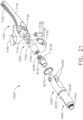
- the shaft assembly 2000 comprises a proximal portion 2100, an elongate shaft 2200 extending from the proximal portion 2100, a distal attachment portion 2400, and an articulation joint 2300 rotatably connecting the distal attachment portion 2400 to the elongate shaft 2200.
- the shaft assembly 2000 further comprises a replaceable end effector assembly 7000 attached to the distal attachment portion 2400.
- the replaceable end effector assembly 7000 comprises a jaw assembly 7100 configured to be opened and closed to clamp and/or manipulate the tissue of a patient.
- the end effector assembly 7000 can be articulated about the articulation joint 2300 and/or rotated relative to the distal attachment portion 2400 about a longitudinal axis to better position the jaw assembly 7100 within the patient, as described in greater detail further below.
- the handle assembly 1000 comprises, among other things, a drive module 1100.
- the drive module 1100 comprises a distal mounting interface which permits a clinician to selectively attach one of the shaft assemblies 2000, 3000, 4000, and 5000, for example, to the drive module 1100.
- the power module 1200 when attached to the drive module 1100, comprises a pistol grip which can allow a clinician to hold the handle 1000 in a manner which places the drive module 1100 on top of the clinician's hand.
- the power module 1300 when attached to the drive module 1100, comprises an end grip which allows a clinician to hold the handle 1000 like a wand.
- the handle drive module 1100 further comprises a frame 1500, a motor assembly 1600, a drive system 1700 operably engaged with the motor assembly 1600, and a control system 1800.
- the motor assembly 1600 comprises an electric motor 1610 including a housing 1620, a drive shaft 1630, and a gear reduction system.
- the control system 1800 is in communication with the motor assembly 1600 and the electrical power circuit of the drive module 1100.
- the control system 1800 is configured to control the power delivered to the motor assembly 1600 from the electrical power circuit.
- the drive system 1700 comprises a rotatable shaft 1710 comprising a splined distal end 1720 and a longitudinal aperture 1730 defined therein.
- the rotatable shaft 1710 is operably mounted to the output shaft of the motor assembly 1600 such that the rotatable shaft 1710 rotates with the motor output shaft.
- the handle frame 1510 extends through the longitudinal aperture 1730 and rotatably supports the rotatable shaft 1710. As a result, the handle frame 1510 serves as a bearing for the rotatable shaft 1710.
- the handle frame 1510 and the rotatable shaft 1710 extend distally from a mounting interface 1130 of the drive module 1110 and are coupled with corresponding components on the shaft assembly 2000 when the shaft assembly 2000 is assembled to the drive module 1100.
- the shaft assembly 2000 further comprises a frame 2500 and a drive system 2700.
- the frame 2500 comprises a longitudinal shaft 2510 extending through the shaft assembly 2000 and a plurality of electrical contacts, or pins, 2520 extending proximally from the shaft 2510.
- the electrical contacts 2520 on the shaft frame 2510 engage the electrical contacts 1520 on the handle frame 1510 and create electrical pathways therebetween.
- the drive system 2700 comprises a rotatable drive shaft 2710 which is operably coupled to the rotatable drive shaft 1710 of the handle 1000 when the shaft assembly 2000 is assembled to the drive module 1100 such that the drive shaft 2710 rotates with the drive shaft 1710.
- the drive shaft 2710 comprises a splined proximal end 2720 which mates with the splined distal end 1720 of the drive shaft 1710 such that the drive shafts 1710 and 2710 rotate together when the drive shaft 1710 is rotated by the motor assembly 1600.
- the shaft assembly 2000 is assembled to the handle 1000 along a longitudinal axis; however, the operable interconnection between the drive shafts 1710 and 2710 and the electrical interconnection between the frames 1510 and 2510 can comprise any suitable configuration which can allow a shaft assembly to be assembled to the handle 1000 in any suitable manner.
- the mounting interface 1130 of the drive module 1110 is configured to be coupled to a corresponding mounting interface on the shaft assemblies 2000, 3000, 4000, and 5000, for example.
- the clinician can maneuver the handle 1000 to insert the end effector 7000 into a patient.
- the end effector 7000 is inserted into the patient through a trocar and then manipulated in order to position the jaw assembly 7100 of the end effector assembly 7000 relative to the patient's tissue.
- Other surgical techniques are envisioned in which the end effector 7000 is inserted into a patient through an open incision, or without the use of the trocar.
- the jaw assembly 7100 may have to be opened and closed several times throughout a surgical technique.
- the shaft assembly 2000 further comprises a clamping trigger system 2600 and a control system 2800.
- control system 2800 of the shaft assembly 2000 comprises a printed circuit board (PCB) 2810, at least one microprocessor 2820, and at least one memory device 2830.
- PCB printed circuit board
- the actuation of the clamping trigger 2610 is detected by the shaft control system 2800 and communicated to the handle control system 1800 via the communication systems 2900 and 1900.
- the handle control system 1800 Upon receiving a signal that the clamping trigger 2610 has been actuated, the handle control system 1800 supplies power to the electric motor 1610 of the motor assembly 1600 to rotate the drive shaft 1710 of the handle drive system 1700, and the drive shaft 2710 of the shaft drive system 2700, in a direction which closes the jaw assembly 7100 of the end effector 7000.
- the mechanism for converting the rotation of the drive shaft 2710 to a closure motion of the jaw assembly 7100 is discussed in greater detail below.
- the handle control system 1800 cuts the electrical power to the electric motor 1610.
- the handle control system 1800 can determine when the jaw assembly 7100 has reached its fully-clamped position in any suitable manner.
- the handle control system 1800 can comprise an encoder system which monitors the rotation of, and counts the rotations of, the output shaft of the electric motor 1610 and, once the number of rotations reaches a predetermined threshold, the handle control system 1800 can discontinue supplying power to the electric motor 1610.
- the end effector assembly 7000 can comprise one or more sensors configured to detect when the jaw assembly 7100 has reached its fully-clamped position.
- the sensors in the end effector 7000 are in signal communication with the handle control system 1800 via electrical circuits extending through the shaft assembly 2000 which can include the electrical contacts 1520 and 2520, for example.
- the switch 2115 is opened which is detected by the shaft control system 2800 and communicated to the handle control system 1800 via the communication systems 2900 and 1900.
- the handle control system 1800 Upon receiving a signal that the clamping trigger 2610 has been moved out of its actuated position, the handle control system 1800 reverses the polarity of the voltage differential being applied to the electric motor 1610 of the motor assembly 1600 to rotate the drive shaft 1710 of the handle drive system 1700, and the drive shaft 2710 of the shaft drive system 2700, in an opposite direction which, as a result, opens the jaw assembly 7100 of the end effector 7000.
- the handle control system 1800 cuts the electrical power to the electric motor 1610.
- the handle control system 1800 can determine when the jaw assembly 7100 has reached its fully-open position in any suitable manner. For instance, the handle control system 1800 can utilize the encoder system and/or the one or more sensors described above to determine the configuration of the jaw assembly 7100. In view of the above, the clinician needs to be mindful about holding the clamping trigger 2610 in its actuated position in order to maintain the jaw assembly 7100 in its clamped configuration as, otherwise, the control system 1800 will open jaw assembly 7100. With this in mind, the shaft assembly 2000 further comprises an actuator latch 2630 configured to releasably hold the clamping trigger 2610 in its actuated position to prevent the accidental opening of the jaw assembly 7100. The actuator latch 2630 can be manually released, or otherwise defeated, by the clinician to allow the clamping trigger 2610 to be rotated distally and open the jaw assembly 7100.
- the clamping trigger 2610 is movable to operate the electric motor 1610 to open or close the jaw assembly 7100 of the end effector 7000.
- the electric motor 1610 is also operable to rotate the end effector 7000 about a longitudinal axis and articulate the end effector 7000 relative to the elongate shaft 2200 about the articulation joint 2300 of the shaft assembly 2000.
- the drive module 1100 comprises an input system 1400 including a rotation actuator 1420 and an articulation actuator 1430.
- the input system 1400 further comprises a printed circuit board (PCB) 1410 which is in signal communication with the printed circuit board (PCB) 1810 of the control system 1800.
- PCB printed circuit board
- the drive module 1100 comprises an electrical circuit, such as a flexible wiring harness or ribbon, for example, which permits the input system 1400 to communicate with the control system 1800.
- the rotation actuator 1420 is rotatably supported on the housing 1110 and is in signal communication with the input board 1410 and/or control board 1810, as described in greater detail below.
- the articulation actuator 1430 is supported by and in signal communication with the input board 1410 and/or control board 1810, as also described in greater detail below.
- the handle housing 1110 comprises an annular groove or slot defined therein adjacent the distal mounting interface 1130.
- the rotation actuator 1420 comprises an annular ring 1422 rotatably supported within the annular groove and, owing to the configuration of the sidewalls of the annular groove, the annular ring 1422 is constrained from translating longitudinally and/or laterally with respect to the handle housing 1110.
- the annular ring 1422 is rotatable in a first, or clockwise, direction and a second, or counter-clockwise direction, about a longitudinal axis extending through the frame 1500 of the drive module 1100.
- the rotation actuator 1420 comprises one or more sensors configured to detect the rotation of the annular ring 1422.
- the rotation actuator 1420 comprises a first sensor positioned on a first side of the drive module 1100 and a second sensor positioned on a second, or opposite, side of the drive module 1100 and the annular ring 1422 comprises a detectable element which is detectable by the first and second sensors.
- the first sensor is configured to detect when the annular ring 1422 is rotated in the first direction and the second sensor is configured to detect when the annular ring 1422 is rotated in the second direction.
- the handle control system 1800 rotates the handle drive shaft 1710, the drive shaft 2710, and the end effector 7000 in the first direction, as described in greater detail below. Similarly, the handle control system 1800 rotates the handle drive shaft 1710, the drive shaft 2710, and the end effector 7000 in the second direction when the second sensor detects that the annular ring 1422 is rotated in the second direction.
- the clamping trigger 2610 and the rotation actuator 1420 are both operable to rotate the drive shaft 2710.
- clamping trigger 2610 and the rotation actuator 1420 are both operable to rotate the drive shaft 2710 and either, respectively, operate the jaw assembly 7100 or rotate the end effector 7000.
- the system that uses the rotation of the drive shaft 2710 to selectively perform these functions is described in greater detail below.
- the articulation actuator 1430 comprises a first push button 1432 and a second push button 1434.
- the first push button 1432 is part of a first articulation control circuit and the second push button 1434 is part of a second articulation circuit of the input system 1400.
- the first push button 1432 comprises a first switch that is closed when the first push button 1432 is depressed.
- the handle control system 1800 is configured to sense the closure of the first switch and, moreover, the closure of the first articulation control circuit. When the handle control system 1800 detects that the first articulation control circuit has been closed, the handle control system 1800 operates the electric motor 1610 to articulate the end effector 7000 in a first articulation direction about the articulation joint 2300.
- the first articulation control circuit is opened which, once detected by the control system 1800, causes the control system 1800 to cut the power to the electric motor 1610 to stop the articulation of the end effector 7000.
- the articulation range of the end effector 7000 is limited and the control system 1800 can utilize the encoder system discussed above for monitoring the rotational output of the electric motor 1610, for example, to monitor the amount, or degree, in which the end effector 7000 is rotated in the first direction.
- the shaft assembly 2000 can comprise a first sensor configured to detect when the end effector 7000 has reached the limit of its articulation in the first direction. In any event, when the control system 1800 determines that the end effector 7000 has reached the limit of articulation in the first direction, the control system 1800 can cut the power to the electric motor 1610 to stop the articulation of the end effector 7000.
- the second push button 1434 comprises a second switch that is closed when the second push button 1434 is depressed.
- the handle control system 1800 is configured to sense the closure of the second switch and, moreover, the closure of the second articulation control circuit.
- the handle control system 1800 detects that the second articulation control circuit has been closed, the handle control system 1800 operates the electric motor 1610 to articulate the end effector 7000 in a second direction about the articulation joint 2300.
- the second articulation control circuit is opened which, once detected by the control system 1800, causes the control system 1800 to cut the power to the electric motor 1610 to stop the articulation of the end effector 7000.
- the articulation range of the end effector 7000 is limited and the control system 1800 can utilize the encoder system discussed above for monitoring the rotational output of the electric motor 1610, for example, to monitor the amount, or degree, in which the end effector 7000 is rotated in the second direction.
- the shaft assembly 2000 can comprise a second sensor configured to detect when the end effector 7000 has reached the limit of its articulation in the second direction. In any event, when the control system 1800 determines that the end effector 7000 has reached the limit of articulation in the second direction, the control system 1800 can cut the power to the electric motor 1610 to stop the articulation of the end effector 7000.
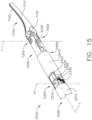
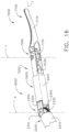
- the end effector 7000 is articulatable in a first direction ( FIG. 16 ) and/or a second direction ( FIG. 17 ) from a center, or unarticulated, position ( FIG. 15 ).
- the clinician can attempt to re-center the end effector 7000 by using the first and second articulation push buttons 1432 and 1434.
- the clinician may struggle to re-center the end effector 7000 as, for instance, the end effector 7000 may not be entirely visible once it is positioned in the patient.
- the end effector 7000 may not fit back through a trocar if the end effector 7000 is not re-centered, or at least substantially re-centered.
- the control system 1800 is configured to provide feedback to the clinician when the end effector 7000 is moved into its unarticulated, or centered, position.
- the feedback comprises audio feedback and the handle control system 1800 can comprise a speaker which emits a sound, such as a beep, for example, when the end effector 7000 is centered.
- the feedback comprises visual feedback and the handle control system 1800 can comprise a light emitting diode (LED), for example, positioned on the handle housing 1110 which flashes when the end effector 7000 is centered.
- the feedback comprises haptic feedback and the handle control system 1800 can comprise an electric motor comprising an eccentric element which vibrates the handle 1000 when the end effector 7000 is centered.
- Manually re-centering the end effector 7000 in this way can be facilitated by the control system 1800 slowing the motor 1610 when the end effector 7000 is approaching its centered position.
- the control system 1800 slows the articulation of the end effector 7000 when the end effector 7000 is within approximately 5 degrees of center in either direction, for example.
- the handle control system 1800 can be configured to re-center the end effector 7000.
- the handle control system 1800 can re-center the end effector 7000 when both of the articulation buttons 1432 and 1434 of the articulation actuator 1430 are depressed at the same time.
- the handle control system 1800 comprises an encoder system configured to monitor the rotational output of the electric motor 1610, for example, the handle control system 1800 can determine the amount and direction of articulation needed to re-center, or at least substantially re-center, the end effector 7000.
- the input system 1400 can comprise a home button, for example, which, when depressed, automatically centers the end effector 7000.
- the elongate shaft 2200 of the shaft assembly 2000 comprises an outer housing, or tube, 2210 mounted to the proximal housing 2110 of the proximal portion 2100.
- the outer housing 2210 comprises a longitudinal aperture 2230 extending therethrough and a proximal flange 2220 which secures the outer housing 2210 to the proximal housing 2110.
- the frame 2500 of the shaft assembly 2000 extends through the longitudinal aperture 2230 of the elongate shaft 2200. More specifically, the shaft 2510 of the shaft frame 2500 necks down into a smaller shaft 2530 which extends through the longitudinal aperture 2230. That said, the shaft frame 2500 can comprise any suitable arrangement.
- the drive system 2700 of the shaft assembly 2000 also extends through the longitudinal aperture 2230 of the elongate shaft 2200. More specifically, the drive shaft 2710 of the shaft drive system 2700 necks down into a smaller drive shaft 2730 which extends through the longitudinal aperture 2230. That said, the shaft drive system 2700 can comprise any suitable arrangement.
- the outer housing 2210 of the elongate shaft 2200 extends to the articulation joint 2300.
- the articulation joint 2300 comprises a proximal frame 2310 mounted to the outer housing 2210 such that there is little, if any, relative translation and/or rotation between the proximal frame 2310 and the outer housing 2210.
- the proximal frame 2310 comprises an annular portion 2312 mounted to the sidewall of the outer housing 2210 and tabs 2314 extending distally from the annular portion 2312.
- the articulation joint 2300 further comprises links 2320 and 2340 which are rotatably mounted to the frame 2310 and mounted to an outer housing 2410 of the distal attachment portion 2400.
- the link 2320 comprises a distal end 2322 mounted to the outer housing 2410. More specifically, the distal end 2322 of the link 2320 is received and fixedly secured within a mounting slot 2412 defined in the outer housing 2410.
- the link 2340 comprises a distal end 2342 mounted to the outer housing 2410. More specifically, the distal end 2342 of the link 2340 is received and fixedly secured within a mounting slot defined in the outer housing 2410.
- the link 2320 comprises a proximal end 2324 rotatably coupled to a tab 2314 of the proximal articulation frame 2310.
- a pin extends through apertures defined in the proximal end 2324 and the tab 2314 to define a pivot axis therebetween.
- the link 2340 comprises a proximal end 2344 rotatably coupled to a tab 2314 of the proximal articulation frame 2310.
- a pin extends through apertures defined in the proximal end 2344 and the tab 2314 to define a pivot axis therebetween.
- the outer housing 6230 further comprises an annular slot, or recess, 6270 defined therein which is configured to receive an O-ring 6275 therein.
- the jaw assembly 7100 of the end effector 7000 comprises a first jaw 7110 and a second jaw 7120.
- the jaws 7110 and 7120 are rotatable between their open and closed positions by a jaw assembly drive including drive links 7140, a drive nut 7150, and a drive screw 6130.
- the drive screw 6130 is selectively rotatable by the drive shaft 2730 of the shaft drive system 2700.
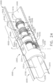
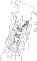
- the drive screw 6130 comprises an annular flange 6132 which is closely received within a slot, or groove, 6232 ( FIG. 25 ) defined in the outer housing 6230 of the end effector 7000.
- the sidewalls of the slot 6232 are configured to prevent, or at least inhibit, longitudinal and/or radial translation between the drive screw 6130 and the outer housing 6230, but yet permit relative rotational motion between the drive screw 6130 and the outer housing 6230.
- the drive screw 6130 further comprises a threaded end 6160 which is threadably engaged with a threaded aperture 7160 defined in the drive nut 7150.
- the drive nut 7150 is constrained from rotating with the drive screw 6130 and, as a result, the drive nut 7150 is translated when the drive screw 6130 is rotated. In use, the drive screw 6130 is rotated in a first direction to displace the drive nut 7150 proximally and in a second, or opposite, direction to displace the drive nut 7150 distally.
- the drive nut 7150 further comprises a distal end 7155 comprising an aperture defined therein which is configured to closely receive pins 7145 extending from the drive links 7140.
- a first drive link 7140 is attached to one side of the distal end 7155 and a second drive link 7140 is attached to the opposite side of the distal end 7155.
- the first drive link 7140 comprises another pin 7145 extending therefrom which is closely received in an aperture defined in the proximal end 7115 of the first jaw 7110 and, similarly, the second drive link 7140 comprises another pin extending therefrom which is closely received in an aperture defined in the proximal end 7125 of the second jaw 7120.
- the drive links 7140 operably connect the jaws 7110 and 7120 to the drive nut 7150.
- the jaws 7110, 7120 are rotated into the closed, or clamped, configuration.
- the jaws 7110, 7120 are rotated into their open configuration when the drive nut 7150 is driven distally by the drive screw 6130.
- control system 1800 is configured to actuate the electric motor 1610 to perform three different end effector functions - clamping/opening the jaw assembly 7100 ( FIGS. 14 and 15 ), rotating the end effector 7000 about a longitudinal axis ( FIGS. 18 and 19 ), and articulating the end effector 7000 about an articulation axis ( FIGS. 16 and 17 ).
- the control system 1800 is configured to operate a transmission 6000 to selectively perform these three end effector functions.
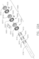
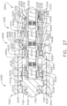
- the transmission 6000 comprises a first clutch system 6100 configured to selectively transmit the rotation of the drive shaft 2730 to the drive screw 6130 of the end effector 7000 to open or close the jaw assembly 7100, depending on the direction in which the drive shaft 2730 is rotated.
- the transmission 6000 further comprises a second clutch system 6200 configured to selectively transmit the rotation of the drive shaft 2730 to the outer housing 6230 of the end effector 7000 to rotate the end effector 7000 about the longitudinal axis L.
- the transmission 6000 also comprises a third clutch system 6300 configured to selectively transmit the rotation of the drive shaft 2730 to the articulation joint 2300 to articulate the distal attachment portion 2400 and the end effector 7000 about the articulation axis A.
- the first clutch system 6100 comprises a first clutch 6110, an expandable first drive ring 6120, and a first electromagnetic actuator 6140.
- the first clutch 6110 comprises an annular ring and is slideably disposed on the drive shaft 2730.
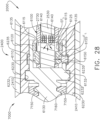
- the first clutch 6110 is comprised of a magnetic material and is movable between a disengaged, or unactuated, position ( FIG. 28 ) and an engaged, or actuated, position ( FIG. 29 ) by electromagnetic fields EF generated by the first electromagnetic actuator 6140.
- the first clutch 6110 is at least partially comprised of iron and/or nickel, for example.
- the first clutch 6110 comprises a permanent magnet. As illustrated in FIG.
- the drive shaft 2730 comprises one or more longitudinal key slots 6115 defined therein which are configured to constrain the longitudinal movement of the clutch 6110 relative to the drive shaft 2730. More specifically, the clutch 6110 comprises one or more keys extending into the key slots 6115 such that the distal ends of the key slots 6115 stop the distal movement of the clutch 6110 and the proximal ends of the key slots 6115 stop the proximal movement of the clutch 6110.
- the first clutch 6110 When the first clutch 6110 is in its disengaged position ( FIG. 28 ), the first clutch 6110 rotates with the drive shaft 2130 but does not transmit rotational motion to the first drive ring 6120. As can be seen in FIG. 28 , the first clutch 6110 is separated from, or not in contact with, the first drive ring 6120. As a result, the rotation of the drive shaft 2730 and the first clutch 6110 is not transmitted to the drive screw 6130 when the first clutch assembly 6100 is in its disengaged state. When the first clutch 6110 is in its engaged position ( FIG. 29 ), the first clutch 6110 is engaged with the first drive ring 6120 such that the first drive ring 6120 is expanded, or stretched, radially outwardly into contact with the drive screw 6130.
- the first drive ring 6120 comprises an elastomeric band, for example.
- the first drive ring 6120 is compressed against an annular inner sidewall 6135 of the drive screw 6130.
- the rotation of the drive shaft 2730 and the first clutch 6110 is transmitted to the drive screw 6130 when the first clutch assembly 6100 is in its engaged state.
- the first clutch assembly 6100 can move the jaw assembly 7100 into its open and closed configurations when the first clutch assembly 6100 is in its engaged state.
- the first electromagnetic actuator 6140 is configured to generate magnetic fields to move the first clutch 6110 between its disengaged ( FIG. 28 ) and engaged ( FIG. 29 ) positions.
- the first electromagnetic actuator 6140 is configured to emit a magnetic field EF L which repulses, or drives, the first clutch 6110 away from the first drive ring 6120 when the first clutch assembly 6100 is in its disengaged state.
- the first electromagnetic actuator 6140 comprises one or more wound coils in a cavity defined in the shaft frame 2530 which generate the magnetic field EF L when current flows in a first direction through a first electrical clutch circuit including the wound coils.
- the control system 1800 is configured to apply a first voltage polarity to the first electrical clutch circuit to create the current flowing in the first direction.
- the control system 1800 can continuously apply the first voltage polarity to the first electric shaft circuit to continuously hold the first clutch 6110 in its disengaged position. While such an arrangement can prevent the first clutch 6110 from unintentionally engaging the first drive ring 6120, such an arrangement can also consume a lot of power.
- the control system 1800 can apply the first voltage polarity to the first electrical clutch circuit for a sufficient period of time to position the first clutch 6110 in its disengaged position and then discontinue applying the first voltage polarity to the first electric clutch circuit, thereby resulting in a lower consumption of power.
- the first clutch assembly 6100 further comprises a first clutch lock 6150 mounted in the drive screw 6130 which is configured to releasably hold the first clutch 6110 in its disengaged position.
- the first clutch lock 6150 is configured to prevent, or at least reduce the possibility of, the first clutch 6110 from becoming unintentionally engaged with the first drive ring 6120.
- the first clutch lock 6150 interferes with the free movement of the first clutch 6110 and holds the first clutch 6110 in position via a friction force and/or an interference force therebetween.
- the first clutch lock 6150 comprises an elastomeric plug, seat, or detent, comprised of rubber, for example.
- the first clutch lock 6150 comprises a permanent magnet which holds the first clutch 6110 in its disengaged position by an electromagnetic force.
- the first electromagnetic actuator 6140 can apply an electromagnetic pulling force to the first clutch 6110 that overcomes these forces, as described in greater detail below.
- the first electromagnetic actuator 6140 is configured to emit a magnetic field EF D which pulls, or drives, the first clutch 6110 toward the first drive ring 6120 when the first clutch assembly 6100 is in its engaged state.
- the coils of the first electromagnetic actuator 6140 generate the magnetic field EF D when current flows in a second, or opposite, direction through the first electrical clutch circuit.
- the control system 1800 is configured to apply an opposite voltage polarity to the first electrical clutch circuit to create the current flowing in the opposite direction.
- the control system 1800 can continuously apply the opposite voltage polarity to the first electrical clutch circuit to continuously hold the first clutch 6110 in its engaged position and maintain the operable engagement between the first drive ring 6120 and the drive screw 6130.
- the first clutch 6110 can be configured to become wedged within the first drive ring 6120 when the first clutch 6110 is in its engaged position and, in such instances, the control system 1800 may not need to continuously apply a voltage polarity to the first electrical clutch circuit to hold the first clutch assembly 6100 in its engaged state. In such instances, the control system 1800 can discontinue applying the voltage polarity once the first clutch 6110 has been sufficiently wedged in the first drive ring 6120.
- the first clutch lock 6150 is also configured to lockout the jaw assembly drive when the first clutch 6110 is in its disengaged position. More specifically, referring again to FIG. 28 , the first clutch 6110 pushes the first clutch lock 6150 in the drive screw 6130 into engagement with the outer housing 6230 of the end effector 7000 when the first clutch 6110 is in its disengaged position such that the drive screw 6130 does not rotate, or at least substantially rotate, relative to the outer housing 6230.
- the outer housing 6230 comprises a slot 6235 defined therein which is configured to receive the first clutch lock 6150.
- the first clutch 6110 is no longer engaged with the first clutch lock 6150 and, as a result, the first clutch lock 6150 is no longer biased into engagement with the outer housing 6230 and the drive screw 6130 can rotate freely with respect to the outer housing 6230.
- the first clutch 6110 can do at least two things - operate the jaw drive when the first clutch 6110 is in its engaged position and lock out the jaw drive when the first clutch 6110 is in its disengaged position.
- the second clutch system 6200 comprises a second clutch 6210, an expandable second drive ring 6220, and a second electromagnetic actuator 6240.
- the second clutch 6210 comprises an annular ring and is slideably disposed on the drive shaft 2730.
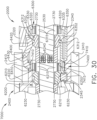
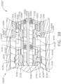
- the second clutch 6210 is comprised of a magnetic material and is movable between a disengaged, or unactuated, position ( FIG. 30 ) and an engaged, or actuated, position ( FIG. 31 ) by electromagnetic fields EF generated by the second electromagnetic actuator 6240.
- the second clutch 6210 is at least partially comprised of iron and/or nickel, for example.
- the second clutch 6210 comprises a permanent magnet. As illustrated in FIG.
- the drive shaft 2730 comprises one or more longitudinal key slots 6215 defined therein which are configured to constrain the longitudinal movement of the second clutch 6210 relative to the drive shaft 2730. More specifically, the second clutch 6210 comprises one or more keys extending into the key slots 6215 such that the distal ends of the key slots 6215 stop the distal movement of the second clutch 6210 and the proximal ends of the key slots 6215 stop the proximal movement of the second clutch 6210.
- the second clutch 6210 When the second clutch 6210 is in its disengaged position, referring to FIG. 30 , the second clutch 6210 rotates with the drive shaft 2730 but does not transmit rotational motion to the second drive ring 6220. As can be seen in FIG. 30 , the second clutch 6210 is separated from, or not in contact with, the second drive ring 6220. As a result, the rotation of the drive shaft 2730 and the second clutch 6210 is not transmitted to the outer housing 6230 of the end effector 7000 when the second clutch assembly 6200 is in its disengaged state. When the second clutch 6210 is in its engaged position ( FIG.
- the second clutch 6210 is engaged with the second drive ring 6220 such that the second drive ring 6220 is expanded, or stretched, radially outwardly into contact with the outer housing 6230.
- the second drive ring 6220 comprises an elastomeric band, for example.
- the second drive ring 6220 is compressed against an annular inner sidewall 7415 of the outer housing 6230.
- the rotation of the drive shaft 2730 and the second clutch 6210 is transmitted to the outer housing 6230 when the second clutch assembly 6200 is in its engaged state.
- the second clutch assembly 6200 can rotate the end effector 7000 in a first direction or a second direction about the longitudinal axis L when the second clutch assembly 6200 is in its engaged state.
- the second electromagnetic actuator 6240 is configured to generate magnetic fields to move the second clutch 6210 between its disengaged ( FIG. 30 ) and engaged ( FIG. 31 ) positions.
- the second electromagnetic actuator 6240 is configured to emit a magnetic field EF L which repulses, or drives, the second clutch 6210 away from the second drive ring 6220 when the second clutch assembly 6200 is in its disengaged state.
- the second electromagnetic actuator 6240 comprises one or more wound coils in a cavity defined in the shaft frame 2530 which generate the magnetic field EF L when current flows in a first direction through a second electrical clutch circuit including the wound coils.
- the control system 1800 is configured to apply a first voltage polarity to the second electrical clutch circuit to create the current flowing in the first direction.
- the control system 1800 can continuously apply the first voltage polarity to the second electric clutch circuit to continuously hold the second clutch 6120 in its disengaged position. While such an arrangement can prevent the second clutch 6210 from unintentionally engaging the second drive ring 6220, such an arrangement can also consume a lot of power.
- the control system 1800 can apply the first voltage polarity to the second electrical clutch circuit for a sufficient period of time to position the second clutch 6210 in its disengaged position and then discontinue applying the first voltage polarity to the second electric clutch circuit, thereby resulting in a lower consumption of power.
- the second clutch assembly 6200 further comprises a second clutch lock 6250 mounted in the outer housing 6230 which is configured to releasably hold the second clutch 6210 in its disengaged position.
- the second clutch lock 6250 can prevent, or at least reduce the possibility of, the second clutch 6210 from becoming unintentionally engaged with the second drive ring 6220.
- the second clutch lock 6250 interferes with the free movement of the second clutch 6210 and holds the second clutch 6210 in position via a friction and/or interference force therebetween.
- the second clutch lock 6250 comprises an elastomeric plug, seat, or detent, comprised of rubber, for example.
- the second clutch lock 6250 comprises a permanent magnet which holds the second clutch 6210 in its disengaged position by an electromagnetic force. That said, the second electromagnetic actuator 6240 can apply an electromagnetic pulling force to the second clutch 6210 that overcomes these forces, as described in greater detail below.
- the second electromagnetic actuator 6240 is configured to emit a magnetic field EF D which pulls, or drives, the second clutch 6210 toward the second drive ring 6220 when the second clutch assembly 6200 is in its engaged state.
- the coils of the second electromagnetic actuator 6240 generate the magnetic field EF D when current flows in a second, or opposite, direction through the second electrical shaft circuit.
- the control system 1800 is configured to apply an opposite voltage polarity to the second electrical shaft circuit to create the current flowing in the opposite direction.
- the control system 1800 can continuously apply the opposite voltage polarity to the second electric shaft circuit to continuously hold the second clutch 6210 in its engaged position and maintain the operable engagement between the second drive ring 6220 and the outer housing 6230.
- the second clutch 6210 can be configured to become wedged within the second drive ring 6220 when the second clutch 6210 is in its engaged position and, in such instances, the control system 1800 may not need to continuously apply a voltage polarity to the second shaft electrical circuit to hold the second clutch assembly 6200 in its engaged state. In such instances, the control system 1800 can discontinue applying the voltage polarity once the second clutch 6210 has been sufficiently wedged in the second drive ring 6220.
- the second clutch lock 6250 is also configured to lockout the rotation of the end effector 7000 when the second clutch 6210 is in its disengaged position. More specifically, referring again to FIG. 30 , the second clutch 6210 pushes the second clutch lock 6250 in the outer shaft 6230 into engagement with the articulation link 2340 when the second clutch 6210 is in its disengaged position such that the end effector 7000 does not rotate, or at least substantially rotate, relative to the distal attachment portion 2400 of the shaft assembly 2000. As illustrated in FIG. 27 , the second clutch lock 6250 is positioned or wedged within a slot, or channel, 2345 defined in the articulation link 2340 when the second clutch 6210 is in its disengaged position.
- the second clutch 6210 can do at least two things - operate the end effector rotation drive when the second clutch 6210 is in its engaged position and lock out the end effector rotation drive when the second clutch 6210 is in its disengaged position.
- the shaft assembly 2000 further comprises an articulation drive system configured to articulate the distal attachment portion 2400 and the end effector 7000 about the articulation joint 2300.
- the articulation drive system comprises an articulation drive 6330 rotatably supported within the distal attachment portion 2400. That said, the articulation drive 6330 is closely received within the distal attachment portion 2400 such that the articulation drive 6330 does not translate, or at least substantially translate, relative to the distal attachment portion 2400.
- the articulation drive system of the shaft assembly 2000 further comprises a stationary gear 2330 fixedly mounted to the articulation frame 2310.
- the stationary gear 2330 is fixedly mounted to a pin connecting a tab 2314 of the articulation frame 2310 and the articulation link 2340 such that the stationary gear 2330 does not rotate relative to the articulation frame 2310.
- the stationary gear 2330 comprises a central body 2335 and an annular array of stationary teeth 2332 extending around the perimeter of the central body 2335.
- the articulation drive 6330 comprises an annular array of drive teeth 6332 which is meshingly engaged with the stationary teeth 2332. When the articulation drive 6330 is rotated, the articulation drive 6330 pushes against the stationary gear 2330 and articulates the distal attachment portion 2400 of the shaft assembly 2000 and the end effector 7000 about the articulation joint 2300.
- the third clutch system 6300 comprises a third clutch 6310, an expandable third drive ring 6320, and a third electromagnetic actuator 6340.
- the third clutch 6310 comprises an annular ring and is slideably disposed on the drive shaft 2730.
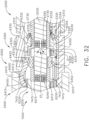
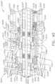
- the third clutch 6310 is comprised of a magnetic material and is movable between a disengaged, or unactuated, position ( FIG. 32 ) and an engaged, or actuated, position ( FIG. 33 ) by electromagnetic fields EF generated by the third electromagnetic actuator 6340.
- the third clutch 6310 is at least partially comprised of iron and/or nickel, for example.
- the third clutch 6310 comprises a permanent magnet. As illustrated in FIG.
- the drive shaft 2730 comprises one or more longitudinal key slots 6315 defined therein which are configured to constrain the longitudinal movement of the third clutch 6310 relative to the drive shaft 2730. More specifically, the third clutch 6310 comprises one or more keys extending into the key slots 6315 such that the distal ends of the key slots 6315 stop the distal movement of the third clutch 6310 and the proximal ends of the key slots 6315 stop the proximal movement of the third clutch 6310.
- the third clutch 6310 When the third clutch 6310 is in its disengaged position, referring to FIG. 32 , the third clutch 6310 rotates with the drive shaft 2730 but does not transmit rotational motion to the third drive ring 6320. As can be seen in FIG. 32 , the third clutch 6310 is separated from, or not in contact with, the third drive ring 6320. As a result, the rotation of the drive shaft 2730 and the third clutch 6310 is not transmitted to the articulation drive 6330 when the third clutch assembly 6300 is in its disengaged state. When the third clutch 6310 is in its engaged position, referring to FIG.
- the third clutch 6310 is engaged with the third drive ring 6320 such that the third drive ring 6320 is expanded, or stretched, radially outwardly into contact with the articulation drive 6330.
- the third drive ring 6320 comprises an elastomeric band, for example.
- the third drive ring 6320 is compressed against an annular inner sidewall 6335 of the articulation drive 6330.
- the rotation of the drive shaft 2730 and the third clutch 6310 is transmitted to the articulation drive 6330 when the third clutch assembly 6300 is in its engaged state.
- the third clutch assembly 6300 can articulate the distal attachment portion 2400 of the shaft assembly 2000 and the end effector 7000 in a first or second direction about the articulation joint 2300.
- the third electromagnetic actuator 6340 is configured to generate magnetic fields to move the third clutch 6310 between its disengaged ( FIG. 32 ) and engaged ( FIG. 33 ) positions.
- the third electromagnetic actuator 6340 is configured to emit a magnetic field EF L which repulses, or drives, the third clutch 6310 away from the third drive ring 6320 when the third clutch assembly 6300 is in its disengaged state.
- the third electromagnetic actuator 6340 comprises one or more wound coils in a cavity defined in the shaft frame 2530 which generate the magnetic field EF L when current flows in a first direction through a third electrical clutch circuit including the wound coils.
- the control system 1800 is configured to apply a first voltage polarity to the third electrical clutch circuit to create the current flowing in the first direction.
- the control system 1800 can continuously apply the first voltage polarity to the third electric clutch circuit to continuously hold the third clutch 6310 in its disengaged position. While such an arrangement can prevent the third clutch 6310 from unintentionally engaging the third drive ring 6320, such an arrangement can also consume a lot of power.
- the control system 1800 can apply the first voltage polarity to the third electrical clutch circuit for a sufficient period of time to position the third clutch 6310 in its disengaged position and then discontinue applying the first voltage polarity to the third electric clutch circuit, thereby resulting in a lower consumption of power.
- the third electromagnetic actuator 6340 is configured to emit a magnetic field EF D which pulls, or drives, the third clutch 6310 toward the third drive ring 6320 when the third clutch assembly 6300 is in its engaged state.
- the coils of the third electromagnetic actuator 6340 generate the magnetic field EF D when current flows in a second, or opposite, direction through the third electrical clutch circuit.
- the control system 1800 is configured to apply an opposite voltage polarity to the third electrical shaft circuit to create the current flowing in the opposite direction.
- the control system 1800 can continuously apply the opposite voltage polarity to the third electric shaft circuit to continuously hold the third clutch 6310 in its engaged position and maintain the operable engagement between the third drive ring 6320 and the articulation drive 6330.
- the third clutch 6210 can be configured to become wedged within the third drive ring 6320 when the third clutch 6310 is in its engaged position and, in such instances, the control system 1800 may not need to continuously apply a voltage polarity to the third shaft electrical circuit to hold the third clutch assembly 6300 in its engaged state. In such instances, the control system 1800 can discontinue applying the voltage polarity once the third clutch 6310 has been sufficiently wedged in the third drive ring 6320.
- the end effector 7000 is articulatable in a first direction or a second direction, depending on the direction in which the drive shaft 2730 is rotated, when the third clutch assembly 6300 is in its engaged state.
- the articulation drive system further comprises a lockout 6350 which prevents, or at least inhibits, the articulation of the distal attachment portion 2400 of the shaft assembly 2000 and the end effector 7000 about the articulation joint 2300 when the third clutch 6310 is in its disengaged position ( FIG. 32 ).
- the articulation link 2340 comprises a slot, or groove, 2350 defined therein wherein the lockout 6350 is slideably positioned in the slot 2350 and extends at least partially under the stationary articulation gear 2330.
- the lockout 6350 comprises at attachment hook 6352 engaged with the third clutch 6310.
- the third clutch 6310 comprises an annular slot, or groove, 6312 defined therein and the attachment hook 6352 is positioned in the annular slot 6312 such that the lockout 6350 translates with the third clutch 6310.
- the lockout 6350 does not rotate, or at least substantially rotate, with the third clutch 6310.
- the annular groove 6312 in the third clutch 6310 permits the third clutch 6310 to rotate relative to the lockout 6350.
- the lockout 6350 further comprises a lockout hook 6354 slideably positioned in a radially-extending lockout slot 2334 defined in the bottom of the stationary gear 2330.
- the lockout 6350 is in a locked position in which the lockout hook 6354 prevents the end effector 7000 from rotating about the articulation joint 2300.
- the lockout 6350 is in an unlocked position in which the lockout hook 6354 is no longer positioned in the lockout slot 2334. Instead, the lockout hook 6354 is positioned in a clearance slot defined in the middle or body 2335 of the stationary gear 2330. In such instances, the lockout hook 6354 can rotate within the clearance slot when the end effector 7000 rotates about the articulation joint 2300.
- the radially-extending lockout slot 2334 depicted in FIGS. 32 and 33 extends longitudinally, i.e., along an axis which is parallel to the longitudinal axis of the elongate shaft 2200.
- the stationary gear 2330 comprises a plurality, or an array, of radially-extending lockout slots 2334 defined in the bottom of the stationary gear 2330 such that, when the third clutch 6310 is deactuated and the lockout 6350 is pulled distally after the end effector 7000 has been articulated, the lockout hook 6354 can enter one of the lockout slots 2334 and lock the end effector 7000 in its articulated position.
- the lockout slots 2334 can define discrete articulated positions for the end effector 7000.
- the lockout 6350 comprises a brake that engages a circumferential shoulder defined in the stationary gear 2330 when the third clutch 6310 is disengaged from the third drive ring 6320.
- the end effector 7000 can be locked in any suitable orientation.
- the lockout 6350 prevents, or at least reduces the possibility of, the end effector 7000 unintentionally articulating.
- the third clutch 6310 can do things - operate the articulation drive when it is in its engaged position and lock out the articulation drive when it is in its disengaged position.
- the shaft frame 2530 and the drive shaft 2730 extend through the articulation joint 2300 into the distal attachment portion 2400.
- the shaft frame 2530 and the drive shaft 2730 bend to accommodate the articulation of the end effector 7000.
- the shaft frame 2530 and the drive shaft 2730 are comprised of any suitable material which accommodates the articulation of the end effector 7000.
- the shaft frame 2530 houses the first, second, and third electromagnetic actuators 6140, 6240, and 6340.
- the first, second, and third electromagnetic actuators 6140, 6240, and 6340 each comprise wound wire coils, such as copper wire coils, for example, and the shaft frame 2530 is comprised of an insulative material to prevent, or at least reduce the possibility of, short circuits between the first, second, and third electromagnetic actuators 6140, 6240, and 6340.
- the first, second, and third electrical clutch circuits extending through the shaft frame 2530 are comprised of insulated electrical wires, for example. Further to the above, the first, second, and third electrical clutch circuits place the electromagnetic actuators 6140, 6240, and 6340 in communication with the control system 1800 in the drive module 1100.
- the clutch system 6000 comprises a first biasing member, such as a spring, for example, configured to bias the first clutch 6110 into its disengaged position, a second biasing member, such as a spring, for example, configured to bias the second clutch 6210 into its disengaged position, and/or a third biasing member, such as a spring, for example, configured to bias the third clutch 6110 into its disengaged position.
- a first biasing member such as a spring
- a second biasing member such as a spring
- a third biasing member such as a spring
- the clutches 6110, 6210, and/or 6310 can be retained in their engaged positions by the drive rings 6120, 6220, and/or 6320, respectively. More specifically, in at least one instance, the drive rings 6120, 6220, and/or 6320 are comprised of an elastic material which grips or frictionally holds the clutches 6110, 6210, and/or 6310, respectively, in their engaged positions.
- the clutch system 6000 comprises a first biasing member, such as a spring, for example, configured to bias the first clutch 6110 into its engaged position, a second biasing member, such as a spring, for example, configured to bias the second clutch 6210 into its engaged position, and/or a third biasing member, such as a spring, for example, configured to bias the third clutch 6110 into its engaged position.
- the biasing forces of the springs can be overcome by the electromagnetic forces applied by the electromagnetic actuators 6140, 6240, and/or 6340, respectively, as needed to selectively hold the clutches 6110, 6210, and 6310 in their disengaged positions.
- the control assembly 1800 can energize one of the electromagnetic actuators to engage one of the clutches while energizing the other two electromagnetic actuators to disengage the other two clutches.
- a clutch system can comprise any suitable number of clutches to control any suitable number of systems.
- the clutches of the clutch system 6000 slide proximally and distally between their engaged and disengaged positions, the clutches of a clutch system can move in any suitable manner.
- the clutches of the clutch system 6000 are engaged one at a time to control one drive motion at a time, various instances are envisioned in which more than one clutch can be engaged to control more than one drive motion at a time.
- the control system 1800 also supplies power to the motor system 1600 to rotate the drive shaft system 2700 in a first direction to clamp the jaw assembly 7100 of the end effector 7000.
- the control system 1800 stops the motor assembly 1600 and deactivates the first clutch assembly 6100.
- the control system 1800 detects that the clamping trigger system 2600 has been moved to, or is being moved to, its unactuated position, the control system 1800 activates, or maintains the activation of, the first clutch assembly 6100 and deactivates, or maintains the deactivation of, the second clutch assembly 6200 and the third clutch assembly 6300.
- the control system 1800 also supplies power to the motor system 1600 to rotate the drive shaft system 2700 in a second direction to open the jaw assembly 7100 of the end effector 7000.
- the control system 1800 activates the second clutch assembly 6200 and deactivates the first clutch assembly 6100 and the third clutch assembly 6300. In such instances, the control system 1800 also supplies power to the motor system 1600 to rotate the drive shaft system 2700 in a first direction to rotate the end effector 7000 in a first direction.
- the control system 1800 detects that the rotation actuator 1420 has been actuated in a second direction, the control system 1800 activates, or maintains the activation of, the second clutch assembly 6200 and deactivates, or maintains the deactivation of, the first clutch assembly 6100 and the third clutch assembly 6300.
- control system 1800 also supplies power to the motor system 1600 to rotate the drive shaft system 2700 in a second direction to rotate the drive shaft system 2700 in a second direction to rotate the end effector 7000 in a second direction.
- control system 1800 detects that the rotation actuator 1420 is not actuated, the control system 1800 deactivates the second clutch assembly 6200.
- the control system 1800 When the first articulation actuator 1432 is depressed, further to the above, the control system 1800 activates the third clutch assembly 6300 and deactivates the first clutch assembly 6100 and the second clutch assembly 6200. In such instances, the control system 1800 also supplies power to the motor system 1600 to rotate the drive shaft system 2700 in a first direction to articulate the end effector 7000 in a first direction.
- the control system 1800 detects that the second articulation actuator 1434 is depressed, the control system 1800 activates, or maintains the activation of, the third clutch assembly 6200 and deactivates, or maintains the deactivation of, the first clutch assembly 6100 and the second clutch assembly 6200.
- control system 1800 also supplies power to the motor system 1600 to rotate the drive shaft system 2700 in a second direction to articulate the end effector 7000 in a second direction.
- control system 1800 detects that neither the first articulation actuator 1432 nor the second articulation actuator 1434 are actuated, the control system 1800 deactivates the third clutch assembly 6200.
- control system 1800 is configured to change the operating mode of the stapling system based on the inputs it receives from the clamping trigger system 2600 of the shaft assembly 2000 and the input system 1400 of the handle 1000.
- the control system 1800 is configured to shift the clutch system 6000 before rotating the shaft drive system 2700 to perform the corresponding end effector function.
- control system 1800 is configured to stop the rotation of the shaft drive system 2700 before shifting the clutch system 6000.
- Such an arrangement can prevent the sudden movements in the end effector 7000.
- the control system 1800 can shift the clutch system 600 while the shaft drive system 2700 is rotating. Such an arrangement can allow the control system 1800 to shift quickly between operating modes.
- the distal attachment portion 2400 of the shaft assembly 2000 comprises an end effector lock 6400 configured to prevent the end effector 7000 from being unintentionally decoupled from the shaft assembly 2000.
- the end effector lock 6400 comprises a lock end 6410 selectively engageable with the annular array of lock notches 7410 defined on the proximal attachment portion 7400 of the end effector 7000, a proximal end 6420, and a pivot 6430 rotatably connecting the end effector lock 6400 to the articulation link 2320.
- the third clutch 6310 is contact with the proximal end 6420 of the end effector lock 6400 such that the lock end 6410 of the end effector lock 6400 is engaged with the array of lock notches 7410.
- the end effector 7000 can rotate relative to the end effector lock 6400 but cannot translate relative to the distal attachment portion 2400.
- the third clutch 6310 is moved into its engaged position, as illustrated in FIG. 35 , the third clutch 6310 is no longer engaged with the proximal end 6420 of the end effector lock 6400. In such instances, the end effector lock 6400 is free to pivot upwardly and permit the end effector 7000 to be detached from the shaft assembly 2000.
- the second clutch 6210 of the second clutch assembly 6200 is in its disengaged position when the clinician detaches, or attempts to detach, the end effector 7000 from the shaft assembly 2000.
- the second clutch 6210 is engaged with the second clutch lock 6250 when the second clutch 6210 is in its disengaged position and, in such instances, the second clutch lock 6250 is pushed into engagement with the articulation link 2340.
- the second clutch lock 6250 is positioned in the channel 2345 defined in the articulation 2340 when the second clutch 6210 is engaged with the second clutch lock 6250 which may prevent, or at least impede, the end effector 7000 from being detached from the shaft assembly 2000.
- the control system 1800 can move the second clutch 6210 into its engaged position in addition to moving the third clutch 6310 into its engaged position. In such instances, the end effector 7000 can clear both the end effector lock 6400 and the second clutch lock 6250 when the end effector 7000 is removed.
- the drive module 1100 comprises an input switch and/or sensor in communication with the control system 1800 via the input system 1400, and/or the control system 1800 directly, which, when actuated, causes the control system 1800 to unlock the end effector 7000.
- FIG. 37 depicts a shaft assembly 2000' in accordance with at least one alternative embodiment.
- the shaft assembly 2000' is similar to the shaft assembly 2000 in many respects, most of which will not be repeated herein for the sake of brevity.
- the shaft assembly 2000' comprises a shaft frame, i.e., shaft frame 2530'.
- the shaft frame 2530' comprises a longitudinal passage 2535' and, in addition, a plurality of clutch position sensors, i.e., a first sensor 6180', a second sensor 6280', and a third sensor 6380' positioned in the shaft frame 2530'.
- the first sensor 6180' is in signal communication with the control system 1800 as part of a first sensing circuit.
- the first sensing circuit comprises signal wires extending through the longitudinal passage 2535'; however, the first sensing circuit can comprise a wireless signal transmitter and receiver to place the first sensor 6180' in signal communication with the control system 1800.
- the first sensor 6180' is positioned and arranged to detect the position of the first clutch 6110 of the first clutch assembly 6100. Based on data received from the first sensor 6180', the control system 1800 can determine whether the first clutch 6110 is in its engaged position, its disengaged position, or somewhere in-between. With this information, the control system 1800 can assess whether or not the first clutch 6110 is in the correct position given the operating state of the surgical instrument.
- the control system 1800 can verify whether the first clutch 6110 is properly positioned in its engaged position. In such instances, further to the below, the control system 1800 can also verify that the second clutch 6210 is in its disengaged position via the second sensor 6280' and that the third clutch 6310 is in its disengaged position via the third sensor 6380'. Correspondingly, the control system 1800 can verify whether the first clutch 6110 is properly positioned in its disengaged position if the surgical instrument is not in its jaw clamping/opening state. To the extent that the first clutch 6110 is not in its proper position, the control system 1800 can actuate the first electromagnetic actuator 6140 in an attempt to properly position the first clutch 6110. Likewise, the control system 1800 can actuate the electromagnetic actuators 6240 and/or 6340 to properly position the clutches 6210 and/or 6310, if necessary.
- the second sensor 6280' is in signal communication with the control system 1800 as part of a second sensing circuit.
- the second sensing circuit comprises signal wires extending through the longitudinal passage 2535'; however, the second sensing circuit can comprise a wireless signal transmitter and receiver to place the second sensor 6280' in signal communication with the control system 1800.
- the second sensor 6280' is positioned and arranged to detect the position of the second clutch 6210 of the first clutch assembly 6200. Based on data received from the second sensor 6280', the control system 1800 can determine whether the second clutch 6210 is in its engaged position, its disengaged position, or somewhere in-between. With this information, the control system 1800 can assess whether or not the second clutch 6210 is in the correct position given the operating state of the surgical instrument.
- the control system 1800 can verify whether the second clutch 6210 is properly positioned in its engaged position. In such instances, the control system 1800 can also verify that the first clutch 6110 is in its disengaged position via the first sensor 6180' and, further to the below, the control system 1800 can also verify that the third clutch 6310 is in its disengaged position via the third sensor 6380'. Correspondingly, the control system 1800 can verify whether the second clutch 6110 is properly positioned in its disengaged position if the surgical instrument is not in its end effector rotation state. To the extent that the second clutch 6210 is not in its proper position, the control system 1800 can actuate the second electromagnetic actuator 6240 in an attempt to properly position the second clutch 6210. Likewise, the control system 1800 can actuate the electromagnetic actuators 6140 and/or 6340 to properly position the clutches 6110 and/or 6310, if necessary.
- the third sensor 6380' is in signal communication with the control system 1800 as part of a third sensing circuit.
- the third sensing circuit comprises signal wires extending through the longitudinal passage 2535'; however, the third sensing circuit can comprise a wireless signal transmitter and receiver to place the third sensor 6380' in signal communication with the control system 1800.
- the third sensor 6380' is positioned and arranged to detect the position of the third clutch 6310 of the third clutch assembly 6300. Based on data received from the third sensor 6380', the control system 1800 can determine whether the third clutch 6310 is in its engaged position, its disengaged position, or somewhere in-between. With this information, the control system 1800 can assess whether or not the third clutch 6310 is in the correct position given the operating state of the surgical instrument.
- the control system 1800 can verify whether the third clutch 6310 is properly positioned in its engaged position. In such instances, the control system 1800 can also verify that the first clutch 6110 is in its disengaged position via the first sensor 6180' and that the second clutch 6210 is in its disengaged position via the second sensor 6280'. Correspondingly, the control system 1800 can verify whether the third clutch 6310 is properly positioned in its disengaged position if the surgical instrument is not in its end effector articulation state. To the extent that the third clutch 6310 is not in its proper position, the control system 1800 can actuate the third electromagnetic actuator 6340 in an attempt to properly position the third clutch 6310. Likewise, the control system 1800 can actuate the electromagnetic actuators 6140 and/or 6240 to properly position the clutches 6110 and/or 6210, if necessary.
- the clutch position sensors i.e., the first sensor 6180', the second sensor 6280', and the third sensor 6380' can comprise any suitable type of sensor.
- the first sensor 6180', the second sensor 6280', and the third sensor 6380' each comprise a proximity sensor.
- the sensors 6180', 6280', and 6380' are configured to detect whether or not the clutches 6110, 6210, and 6310, respectively, are in their engaged positions.
- the first sensor 6180', the second sensor 6280', and the third sensor 6380' each comprise a Hall Effect sensor, for example.
- the sensors 6180', 6280', and 6380' can not only detect whether or not the clutches 6110, 6210, and 6310, respectively, are in their engaged positions but the sensors 6180', 6280', and 6380' can also detect how close the clutches 6110, 6210, and 6310 are with respect to their engaged or disengaged positions.
- FIG. 38 depicts the shaft assembly 2000' and an end effector 7000" in accordance with at least one alternative embodiment.
- the end effector 7000" is similar to the end effector 7000 in many respects, most of which will not be repeated herein for the sake of brevity.
- the shaft assembly 7000" comprises a jaw assembly 7100 and a jaw assembly drive configured to move the jaw assembly 7100 between its open and closed configurations.
- the jaw assembly drive comprises drive links 7140, a drive nut 7150", and a drive screw 6130".
- the drive nut 7150" comprises a sensor 7190" positioned therein which is configured to detect the position of a magnetic element 6190" positioned in the drive screw 6130".
- the magnetic element 6190" is positioned in an elongate aperture 6134" defined in the drive screw 6130" and can comprise a permanent magnet and/or can be comprised of iron, nickel, and/or any suitable metal, for example.
- the sensor 7190" comprises a proximity sensor, for example, which is in signal communication with the control system 1800.
- the sensor 7190" comprises a Hall Effect sensor, for example, in signal communication with the control system 1800.
- the sensor 7190" comprises an optical sensor, for example, and the detectable element 6190" comprises an optically detectable element, such as a reflective element, for example.
- the sensor 7190" is configured to communicate wirelessly with the control system 1800 via a wireless signal transmitter and receiver and/or via a wired connection extending through the shaft frame passage 2532', for example.
- the sensor 7190 is configured to detect when the magnetic element 6190" is adjacent to the sensor 7190" such that the control system 1800 can use this data to determine that the jaw assembly 7100 has reached the end of its clamping stroke. At such point, the control system 1800 can stop the motor assembly 1600.
- the sensor 7190" and the control system 1800 are also configured to determine the distance between where the drive screw 6130" is currently positioned and where the drive screw 6130" should be positioned at the end of its closure stroke in order to calculate the amount of closure stroke of the drive screw 6130" that is still needed to close the jaw assembly 7100.
- such information can be used by the control system 1800 to assess the current configuration of the jaw assembly 7100, i.e., whether the jaw assembly 7100 is in its open configuration, its closed configuration, or a partially closed configuration.
- the sensor system could be used to determine when the jaw assembly 7100 has reached its fully open position and stop the motor assembly 1600 at that point.
- the control system 1800 could use this sensor system to confirm that the first clutch assembly 6100 is in its actuated state by confirming that the jaw assembly 7100 is moving while the motor assembly 1600 is turning.
- the control system 1800 could use this sensor system to confirm that the first clutch assembly 6100 is in its unactuated state by confirming that the jaw assembly 7100 is not moving while the motor assembly 1600 is turning.
- FIG. 39 depicts a shaft assembly 2000′′′ and an end effector 7000′′′ in accordance with at least one alternative embodiment.
- the shaft assembly 2000′′′ is similar to the shaft assemblies 2000 and 2000' in many respects, most of which will not be repeated herein for the sake of brevity.
- the end effector 7000′′′ is similar to the end effectors 7000 and 7000" in many respects, most of which will not be repeated herein for the sake of brevity.
- the end effector 7000′′′ comprises a jaw assembly 7100 and a jaw assembly drive configured to move the jaw assembly 7100 between its open and closed configurations and, in addition, an end effector rotation drive that rotates the end effector 7000′′′ relative to the distal attachment portion 2400 of the shaft assembly 2000'.
- the end effector rotation drive comprises an outer housing 6230′′′ that is rotated relative to a shaft frame 2530′′′ of the end effector 7000′′′ by the second clutch assembly 6200.
- the shaft frame 2530′′′ comprises a sensor 6290′′′ positioned therein which is configured to detect the position of a magnetic element 6190′′′ positioned in and/or on the outer housing 6230"'.
- the magnetic element 6190′′′ can comprise a permanent magnet and/or can be comprised of iron, nickel, and/or any suitable metal, for example.
- the sensor 6290′′′ comprises a proximity sensor, for example, in signal communication with the control system 1800.
- the sensor 6290′′′ comprises a Hall Effect sensor, for example, in signal communication with the control system 1800.
- the sensor 6290′′′ is configured to communicate wirelessly with the control system 1800 via a wireless signal transmitter and receiver and/or via a wired connection extending through the shaft frame passage 2532', for example.
- the control system 1800 can use the sensor 6290′′′ to confirm whether the magnetic element 6190′′′ is rotating and, thus, confirm that the second clutch assembly 6200 is in its actuated state.
- control system 1800 can use the sensor 6290′′′ to confirm whether the magnetic element 6190′′′ is not rotating and, thus, confirm that the second clutch assembly 6200 is in its unactuated state.
- the control system 1800 can also use the sensor 6290′′′ to confirm that the second clutch assembly 6200 is in its unactuated state by confirming that the second clutch 6210 is positioned adjacent the sensor 6290"'.
- FIG. 40 depicts a shaft assembly 2000 ⁇ in accordance with at least one alternative embodiment.
- the shaft assembly 2000 ⁇ is similar to the shaft assemblies 2000, 2000', and 2000′′′ in many respects, most of which will not be repeated herein for the sake of brevity.
- the shaft assembly 2000 ⁇ comprises, among other things, an elongate shaft 2200, an articulation joint 2300, and a distal attachment portion 2400 configured to receive an end effector, such as end effector 7000', for example.
- the shaft assembly 2000 ⁇ comprises an articulation drive, i.e., articulation drive 6330 ⁇ configured to rotate the distal attachment portion 2400 and the end effector 7000' about the articulation joint 2300.
- a shaft frame 2530 ⁇ comprises a sensor positioned therein configured to detect the position, and/or rotation, of a magnetic element 6390 ⁇ positioned in and/or on the articulation drive 6330 ⁇ .
- the magnetic element 6390 ⁇ can comprise a permanent magnet and/or can be comprised of iron, nickel, and/or any suitable metal, for example.
- the sensor comprises a proximity sensor, for example, in signal communication with the control system 1800.
- the sensor comprises a Hall Effect sensor, for example, in signal communication with the control system 1800. In either event, the sensor is configured to communicate wirelessly with the control system 1800 via a wireless signal transmitter and receiver and/or via a wired connection extending through the shaft frame passage 2532', for example.
- control system 1800 can use the sensor to confirm whether the magnetic element 6390 ⁇ is rotating and, thus, confirm that the third clutch assembly 6300 is in its actuated state. Similarly, the control system 1800 can use the sensor to confirm whether the magnetic element 6390 ⁇ is not rotating and, thus, confirm that the third clutch assembly 6300 is in its unactuated state. In certain instances, the control system 1800 can use the sensor to confirm that the third clutch assembly 6300 is in its unactuated state by confirming that the third clutch 6310 is positioned adjacent the sensor.
- the shaft assembly 2000 ⁇ comprises an end effector lock 6400' configured to releasably lock the end effector 7000', for example, to the shaft assembly 2000 ⁇ .
- the end effector lock 6400' is similar to the end effector lock 6400 in many respects, most of which will not be discussed herein for the sake of brevity.
- a proximal end 6420' of the lock 6400' comprises a tooth 6422' configured to engage the annular slot 6312 of the third clutch 6310 and releasably hold the third clutch 6310 in its disengaged position. That said, the actuation of the third electromagnetic assembly 6340 can disengage the third clutch 6310 from the end effector lock 6400'.
- the proximal movement of the third clutch 6310 into its engaged position rotates the end effector lock 6400' into a locked position and into engagement with the lock notches 7410 to lock the end effector 7000' to the shaft assembly 2000 ⁇ .
- the distal movement of the third clutch 6310 into its disengaged position unlocks the end effector 7000' and allows the end effector 7000' to be disassembled from the shaft assembly 2000 ⁇ .
- an instrument system including a handle and a shaft assembly attached thereto can be configured to perform a diagnostic check to assess the state of the clutch assemblies 6100, 6200, and 6300.
- the control system 1800 sequentially actuates the electromagnetic actuators 6140, 6240, and/or 6340 - in any suitable order - to verify the positions of the clutches 6110, 6210, and/or 6310, respectively, and/or verify that the clutches are responsive to the electromagnetic actuators and, thus, not stuck.
- the control system 1800 can use sensors, including any of the sensors disclosed herein, to verify the movement of the clutches 6110, 6120, and 6130 in response to the electromagnetic fields created by the electromagnetic actuators 6140, 6240, and/or 6340.
- the diagnostic check can also include verifying the motions of the drive systems.
- the control system 1800 sequentially actuates the electromagnetic actuators 6140, 6240, and/or 6340 - in any suitable order - to verify that the jaw drive opens and/or closes the jaw assembly 7100, the rotation drive rotates the end effector 7000, and/or the articulation drive articulates the end effector 7000, for example.
- the control system 1800 can use sensors to verify the motions of the jaw assembly 7100 and end effector 7000.
- the control system 1800 can perform the diagnostic test at any suitable time, such as when a shaft assembly is attached to the handle and/or when the handle is powered on, for example. If the control system 1800 determines that the instrument system passed the diagnostic test, the control system 1800 can permit the ordinary operation of the instrument system. If the control system 1800 determines that the instrument system failed the diagnostic test, the control system 1800 can prevent and/or modify the operation of the instrument system.
- FIGS. 41-43 depict a clutch system 6000' in accordance with at least one alternative embodiment.
- the clutch system 6000' is similar to the clutch system 6000 in many respects, most of which will not be repeated herein for the sake of brevity.
- the clutch system 6000' comprises a clutch assembly 6100' which is actuatable to selectively couple a rotatable drive input 6030' with a rotatable drive output 6130'.
- the clutch assembly 6100' comprises clutch plates 6110' and drive rings 6120'.
- the clutch plates 6110' are comprised of a magnetic material, such as iron and/or nickel, for example, and can comprise a permanent magnet.
- the clutch plates 6110' are movable between unactuated positions ( FIG. 42 ) and actuated positions ( FIG. 43 ) within the drive output 6130'.
- the clutch plates 6110' are slideably positioned in apertures defined in the drive output 6130' such that the clutch plates 6110' rotate with the drive output 6130' regardless of whether the clutch plates 6110' are in their unactuated or actuated positions.
- the clutch plates 6110' When the clutch plates 6110' are in their unactuated positions, as illustrated in FIG. 42 , the rotation of the drive input 6030' is not transferred to the drive output 6130'. More specifically, when the drive input 6030' is rotated, in such instances, the drive input 6030' slides past and rotates relative to the drive rings 6120' and, as a result, the drive rings 6120' do not drive the clutch plates 6110' and the drive output 6130'.
- the clutch plates 6110' When the clutch plates 6110' are in their actuated positions, as illustrated in FIG. 43 , the clutch plates 6110' resiliently compress the drive rings 6120' against the drive input 6030'.
- the drive rings 6120' are comprised of any suitable compressible material, such as rubber, for example.
- the clutch system 6000' comprises a clutch actuator 6140' configured to move the clutch plates 6110' into their actuated positions.
- the clutch actuator 6140' is comprised of a magnetic material such as iron and/or nickel, for example, and can comprise a permanent magnet.
- the clutch actuator 6140' is slideably positioned in a longitudinal shaft frame 6050' extending through the drive input 6030' and can be moved between an unactuated position ( FIG. 42 ) and an actuated position ( FIG. 43 ) by a clutch shaft 6060'.
- the clutch shaft 6060' comprises a polymer cable, for example.
- the clutch actuator 6140' When the clutch actuator 6140' is in its actuated position, as illustrated in FIG. 43 , the clutch actuator 6140' pulls the clutch plates 6110' inwardly to compress the drive rings 6120', as discussed above. When the clutch actuator 6140' is moved into its unactuated position, as illustrated in FIG. 42 , the drive rings 6120' resiliently expand and push the clutch plates 6110' away from the drive input 6030'.
- the clutch actuator 6140' can comprise an electromagnet. In such an arrangement, the clutch actuator 6140' can be actuated by an electrical circuit extending through a longitudinal aperture defined in the clutch shaft 6060', for example. In various instances, the clutch system 6000' further comprises electrical wires 6040', for example, extending through the longitudinal aperture.
- FIG. 44 depicts an end effector 7000a including a jaw assembly 7100a, a jaw assembly drive, and a clutch system 6000a in accordance with at least one alternative embodiment.
- the jaw assembly 7100a comprises a first jaw 7110a and a second jaw 7120a which are selectively rotatable about a pivot 7130a.
- the jaw assembly drive comprises a translatable actuator rod 7160a and drive links 7140a which are pivotably coupled to the actuator rod 7160a about a pivot 7150a.
- the drive links 7140a are also pivotably coupled to the jaws 7110a and 7120a such that the jaws 7110a and 7120a are rotated closed when the actuator rod 7160a is pulled proximally and rotated open when the actuator rod 7160a is pushed distally.
- the clutch system 6000a is similar to the clutch systems 6000 and 6000' in many respects, most of which will not be repeated herein for the sake of brevity.
- the clutch system 6000a comprises a first clutch assembly 6100a and a second clutch assembly 6200a which are configured to selectively transmit the rotation of a drive input 6030a to rotate the jaw assembly 7100a about a longitudinal axis and articulate the jaw assembly 7100a about an articulation joint 7300a, respectively, as described in greater detail below.
- the first clutch assembly 6100a comprises clutch plates 6110a and drive rings 6120a and work in a manner similar to the clutch plates 6110' and drive rings 6120' discussed above.
- the clutch pates 6110a are actuated by an electromagnetic actuator 6140a, the rotation of the drive input 6030a is transferred to an outer shaft housing 7200a.
- the outer shaft housing 7200a comprises a proximal outer housing 7210a and a distal outer housing 7220a which is rotatably supported by the proximal outer housing 7210a and is rotated relative to the proximal outer housing 7210a by the drive input 6030a when the clutch plates 6110a are in their actuated position.
- the rotation of the distal outer housing 7220a rotates the jaw assembly 7100a about the longitudinal axis owing to fact that the pivot 7130a of the jaw assembly 7100a is mounted to the distal outer housing 7220a.
- the outer shaft housing 7200a rotates the jaw assembly 7100a in a first direction when the outer shaft housing 7200a is rotated in a first direction by the drive input 6030a.
- the outer shaft housing 7200a rotates the jaw assembly 7100a in a second direction when the outer shaft housing 7200a is rotated in a second direction by the drive input 6030a.
- the electromagnetic actuator 6140a is de-energized, the drive rings 6120a expand and the clutch plates 6110a are moved into their unactuated positions, thereby decoupling the end effector rotation drive from the drive input 6030a.
- the second clutch assembly 6200a comprises clutch plates 6210a and drive rings 6220a and work in a manner similar to the clutch plates 6110' and drive rings 6120' discussed above.
- the clutch pates 6210a are actuated by an electromagnetic actuator 6240a, the rotation of the drive input 6030a is transferred to an articulation drive 6230a.
- the articulation drive 6230a is rotatably supported within an outer shaft housing 7410a of an end effector attachment portion 7400a and is rotatably supported by a shaft frame 6050a extending through the outer shaft housing 7410a.
- the articulation drive 6230a comprises a gear face defined thereon which is operably intermeshed with a stationary gear face 7230a defined on the proximal outer housing 7210a of the outer shaft housing 7200a.
- the articulation drive 6230a articulates the outer shaft housing 7200a and the jaw assembly 7100a in a first direction when the articulation drive 6230a is rotated in a first direction by the drive input 6030a.
- the articulation drive 6230a articulates the outer shaft housing 7200a and the jaw assembly 7100a in a second direction when the articulation drive 6230a is rotated in a second direction by the drive input 6030a.
- the electromagnetic actuator 6240a is de-energized, the drive rings 6220a expand and the clutch plates 6210a are moved into their unactuated positions, thereby decoupling the end effector articulation drive from the drive input 6030a.
- the shaft assembly 4000 is illustrated in FIGS. 45-49 .
- the shaft assembly 4000 is similar to the shaft assemblies 2000, 2000', 2000′′′, and 2000 ⁇ in many respects, most of which will not be repeated herein for the sake of brevity.
- the frame 4500 of the shaft assembly 4000 comprises a frame shaft 4510.
- the frame shaft 4510 comprises a notch, or cut-out, 4530 defined therein.
- the cut-out 4530 is configured to provide clearance for a jaw closure actuation system 4600.
- the frame 4500 further comprises a distal portion 4550 and a bridge 4540 connecting the distal portion 4550 to the frame shaft 4510.
- the frame 4500 further comprises a longitudinal portion 4560 extending through the elongate shaft 4200 to the distal attachment portion 2400. Similar to the above, the frame shaft 4510 comprises one or more electrical traces defined thereon and/or therein.
- the electrical traces extend through the longitudinal portion 4560, the distal portion 4550, the bridge 4540, and/or any suitable portion of the frame shaft 4510 to the electrical contacts 2520.
- the distal portion 4550 and longitudinal portion 4560 comprise a longitudinal aperture defined therein which is configured to receive a rod 4660 of the jaw closure actuation system 4600, as described in greater detail below.
- the drive system 4700 of the shaft assembly 4000 comprises a drive shaft 4710.
- the drive shaft 4710 is rotatably supported within the proximal shaft housing 4110 by the frame shaft 4510 and is rotatable about a longitudinal axis extending through the frame shaft 4510.
- the drive system 4700 further comprises a transfer shaft 4750 and an output shaft 4780.
- the transfer shaft 4750 is also rotatably supported within the proximal shaft housing 4110 and is rotatable about a longitudinal axis extending parallel to, or at least substantially parallel to, the frame shaft 4510 and the longitudinal axis defined therethrough.
- the transfer shaft 4750 comprises a proximal spur gear 4740 fixedly mounted thereto such that the proximal spur gear 4740 rotates with the transfer shaft 4750.
- the proximal spur gear 4740 is operably intermeshed with an annular gear face 4730 defined around the outer circumference of the drive shaft 4710 such that the rotation of the drive shaft 4710 is transferred to the transfer shaft 4750.
- the transfer shaft 4750 further comprises a distal spur gear 4760 fixedly mounted thereto such that the distal spur gear 4760 rotates with the transfer shaft 4750.
- the distal spur gear 4760 is operably intermeshed with an annular gear 4770 defined around the outer circumference of the output shaft 4780 such that the rotation of the transfer shaft 4750 is transferred to the output shaft 4780.
- the output shaft 4780 is rotatably supported within the proximal shaft housing 4110 by the distal portion 4550 of the shaft frame 4500 such that the output shaft 4780 rotates about the longitudinal shaft axis.
- the output shaft 4780 is not directly coupled to the input shaft 4710; rather, the output shaft 4780 is operably coupled to the input shaft 4710 by the transfer shaft 4750.
- Such an arrangement provides room for the manually-actuated jaw closure actuation system 4600 discussed below.
- the jaw closure actuation system 4600 comprises an actuation, or scissors, trigger 4610 rotatably coupled to the proximal shaft housing 4110 about a pivot 4620.
- the actuation trigger 4610 comprises an elongate portion 4612, a proximal end 4614, and a grip ring aperture 4616 defined in the proximal end 4614 which is configured to be gripped by the clinician.
- the shaft assembly 4000 further comprises a stationary grip 4160 extending from the proximal housing 4110.
- the stationary grip 4160 comprises an elongate portion 4162, a proximal end 4164, and a grip ring aperture 4166 defined in the proximal end 4164 which is configured to be gripped by the clinician.
- the actuation trigger 4610 is rotatable between an unactuated position and an actuated position ( FIG. 48 ), i.e., toward the stationary grip 4160, to close the jaw assembly 8100 of the end effector 8000.
- the jaw closure actuation system 4600 further comprises a drive link 4640 rotatably coupled to the proximal shaft housing 4110 about a pivot 4650 and, in addition, an actuation rod 4660 operably coupled to the drive link 4640.
- the actuation rod 4660 extends through an aperture defined in the longitudinal frame portion 4560 and is translatable along the longitudinal axis of the shaft frame 4500.
- the actuation rod 4660 comprises a distal end operably coupled to the jaw assembly 8100 and a proximal end 4665 positioned in a drive slot 4645 defined in the drive link 4640 such that the actuation rod 4660 is translated longitudinally when the drive link 4640 is rotated about the pivot 4650.
- the proximal end 4665 is rotatably supported within the drive slot 4645 such that the actuation rod 4660 can rotate with the end effector 8000.
- the actuation trigger 4610 further comprises a drive arm 4615 configured to engage and rotate the drive link 4640 proximally, and translate the actuation rod 4660 proximally, when the actuation trigger 4610 is actuated, i.e., moved closer to the proximal shaft housing 4110.
- the proximal rotation of the drive link 4640 resiliently compresses a biasing member, such as a coil spring 4670, for example, positioned intermediate the drive link 4640 and the frame shaft 4510.
- a biasing member such as a coil spring 4670
- the distal rotation of the drive link 4640 drives, and automatically rotates, the actuation trigger 4610 back into its unactuated position. That being said, the clinician could manually return the actuation trigger 4610 back into its unactuated position. In such instances, the actuation trigger 4610 could be opened slowly.
- the shaft assembly 4000 further comprises a lock configured to releasably hold the actuation trigger 4610 in its actuated position such that the clinician can use their hand to perform another task without the jaw assembly 8100 opening unintentionally.
- the actuation rod 4660 can be pushed distally to close the jaw assembly 8100.
- the actuation rod 4660 is mounted directly to the actuation trigger 4610 such that, when the actuation trigger 4610 is actuated, the actuation trigger 4610 drives the actuation rod 4660 distally.
- the actuation trigger 4610 can compress a spring when the actuation trigger 4610 is closed such that, when the actuation trigger 4610 is released, the actuation rod 4660 is pushed proximally.
- the shaft assembly 4000 has three functions - opening/closing the jaw assembly of an end effector, rotating the end effector about a longitudinal axis, and articulating the end effector about an articulation axis.
- the end effector rotation and articulation functions of the shaft assembly 4000 are driven by the motor assembly 1600 and the control system 1800 of the drive module 1100 while the jaw actuation function is manually-driven by the jaw closure actuation system 4600.
- the jaw closure actuation system 4600 could be a motor-driven system but, instead, the jaw closure actuation system 4600 has been kept a manually-driven system such that the clinician can have a better feel for the tissue being clamped within the end effector.
- motorizing the jaw closure actuation system 4600 may cause the clinician to lose a tactile sense of the force being applied to the tissue and may not be able to assess whether the force is insufficient or excessive. Thus, the jaw closure actuation system 4600 is manually-driven even though the end effector rotation and articulation systems are motor-driven.
- FIG. 50 is a logic diagram of the control system 1800 of the surgical system depicted in FIG. 1 in accordance with at least one embodiment.
- the control system 1800 comprises a control circuit.
- the control circuit includes a microcontroller 1840 comprising a processor 1820 and a memory 1830.
- One or more sensors such as sensors 1880, 1890, 6180', 6280', 6380', 7190", and/or 6290"', for example, provide real time feedback to the processor 1820.
- the control system 1800 further comprises a motor driver 1850 configured to control the electric motor 1610 and a tracking system 1860 configured to determine the position of one or more longitudinally movable components in the surgical instrument, such as the clutches 6110, 6120, and 6130 and/or the longitudinally-movable drive nut 7150 of the jaw assembly drive, for example.
- the tracking system 1860 is also configured to determine the position of one or more rotational components in the surgical instrument, such as the drive shaft 2530, the outer shaft 6230, and/or the articulation drive 6330, for example.
- the tracking system 1860 provides position information to the processor 1820, which can be programmed or configured to, among other things, determine the position of the clutches 6110, 6120, and 6130 and the drive nut 7150 as well as the orientation of the jaws 7110 and 7120.
- the motor driver 1850 may be an A3941 available from Allegro Microsystems, Inc., for example; however, other motor drivers may be readily substituted for use in the tracking system 1860. A detailed description of an absolute positioning system is described in U.S. Patent Application Publication No. 2017/0296213.
- the microcontroller 1840 is programmed to perform various functions such as precisely controlling the speed and/or position of the drive nut 7150 of the jaw closure assembly, for example.
- the microcontroller 1840 is also programmed to precisely control the rotational speed and position of the end effector 7000 and the articulation speed and position of the end effector 7000.
- the microcontroller 1840 computes a response in the software of the microcontroller 1840.
- the computed response is compared to a measured response of the actual system to obtain an "observed" response, which is used for actual feedback decisions.
- the observed response is a favorable, tuned, value that balances the smooth, continuous nature of the simulated response with the measured response, which can detect outside influences on the system.
- the tracking system 1860 comprises a controlled motor drive circuit arrangement comprising one or more position sensors, such as sensors 1880, 1890, 6180', 6280', 6380', 7190", and/or 6290′′′, for example.
- the position sensors for an absolute positioning system provide a unique position signal corresponding to the location of a displacement member.
- displacement member is used generically to refer to any movable member of the surgical system. In various instances, the displacement member may be coupled to any position sensor suitable for measuring linear displacement.
- the position sensors 1880, 1890, 6180', 6280', 6380', 7190", and/or 6290′′′ may comprise any number of magnetic sensing elements, such as, for example, magnetic sensors classified according to whether they measure the total magnetic field or the vector components of the magnetic field.
- one or more of the position sensors of the tracking system 1860 comprise a magnetic rotary absolute positioning system.
- the tracking system 1860 may comprise and/or be programmed to implement a feedback controller, such as a PID, state feedback, and adaptive controller.
- a power source converts the signal from the feedback controller into a physical input to the system, in this case voltage.
- Other examples include pulse width modulation (PWM) and/or frequency modulation (FM) of the voltage, current, and force.
- PWM pulse width modulation
- FM frequency modulation
- Other sensor(s) may be provided to measure physical parameters of the physical system in addition to position.
- the other sensor(s) can include sensor arrangements such as those described in U.S. Patent No. 9,345,481 , ; U.S. Patent Application Publication No. 2014/0263552 , ; and U.S. Patent Application Publication No. 2018/0360452 , .
- absolute positioning system is coupled to a digital data acquisition system where the output of the absolute positioning system will have finite resolution and sampling frequency.
- the absolute positioning system may comprise a compare and combine circuit to combine a computed response with a measured response using algorithms such as weighted average and theoretical control loop that drives the computed response towards the measured response.
- the computed response of the physical system takes into account properties like mass, inertial, viscous friction, inductance resistance, etc., to predict what the states and outputs of the physical system will be by knowing the input.
- a sensor 1880 comprising a strain gauge or a micro-strain gauge, for example, is configured to measure one or more parameters of the end effector, such as, for example, the strain experienced by the jaws 7110 and 7120 during a clamping operation. The measured strain is converted to a digital signal and provided to the processor 1820.
- a sensor 1890 comprising a load sensor, for example, can measure the closure force applied by the closure drive system to the jaws 7110 and 7120.
- a current sensor 1870 can be employed to measure the current drawn by the motor 1610.
- the force required to clamp the jaw assembly 7100 can correspond to the current drawn by the motor 1610, for example.
- the measured force is converted to a digital signal and provided to the processor 1820.
- a magnetic field sensor can be employed to measure the thickness of the captured tissue. The measurement of the magnetic field sensor can also be converted to a digital signal and provided to the processor 1820.
- the measurements of the tissue compression, the tissue thickness, and/or the force required to close the end effector on the tissue as measured by the sensors can be used by the controller 1840 to characterize the position and/or speed of the movable member being tracked.
- the drive module 1100 of the handle 1000 and/or the shaft assemblies 2000, 3000, 4000, and/or 5000, for example, attachable thereto comprise control systems.
- Each of the control systems can comprise a circuit board having one or more processors and/or memory devices.
- the control systems are configured to store sensor data, for example. They are also configured to store data which identifies the shaft assembly to the handle 1000. Moreover, they are also configured to store data including whether or not the shaft assembly has been previously used and/or how many times the shaft assembly has been used. This information can be obtained by the handle 1000 to assess whether or not the shaft assembly is suitable for use and/or has been used less than a predetermined number of times, for example.
- a shaft assembly 9000 is illustrated in FIGS. 51-69 .
- the shaft assembly 9000 is similar to the shaft assemblies 2000, 3000, 4000, and 5000 in many respects, most of which will not be discussed herein for the sake of brevity.
- the shaft assembly 9000 comprises a proximal portion 9100, an elongate shaft 9200 extending from the proximal portion 9100, a distal attachment portion 9400, and an articulation joint 9300.
- the proximal portion 9100 comprises an interface 9130 configured to be attached to a handle, such as the handle 1000, for example.
- the articulation joint 9300 rotatably connects the distal attachment portion 9400 to the elongate shaft 9200.
- the shaft assembly 9000 further comprises an end effector assembly 9500 attached to the distal attachment portion 9400.
- the end effector assembly 9500 comprises a first jaw 9510 and a second jaw 9520 configured to be opened and closed to clamp and/or manipulate the tissue of a patient.
- the end effector assembly 9500 can be articulated about the articulation joint 9300 and/or rotated relative to the distal attachment portion 9400 about a longitudinal axis LA to better situate the jaws 9510 and 9520 within a patient in order to perform various end effector functions, as will be described in greater detail below.
- the shaft assembly 9000 comprises a drive assembly 9700 supported on a frame 9110 in the proximal shaft portion 9100.
- the drive assembly 9700 is capable of being operated in two configurations - a shifting configuration and a drive configuration. Moreover, as discussed in greater detail below, the drive assembly 9700 is configured to provide three end effector functions by way of one rotary input.
- the drive assembly 9700 comprises a first, or input, rotatable drive shaft 9710 configured to transfer rotational motions from a drive motor 9120 (illustrated in FIG. 51 ) to a main gear 9720 of the drive assembly 9700. Referring to FIGS.
- the input drive shaft 9710 is rotatable about a first rotation axis RA, and is rotatably supported by the frame 9110.
- the main gear 9720 is mounted to the input drive shaft 9710 such that the main gear 9720 rotates with the input drive shaft 9710.
- the drive assembly 9700 further comprises a second, or output, rotatable drive shaft 9740.
- the output drive shaft 9740 is rotatable about a second rotation axis RA 2 and is also rotatably supported by the frame 9110.
- the drive assembly 9700 also comprises a first rotatable gear 9730 and a second rotatable gear 9830 which are selectively engageable with the main gear 9720.
- the shaft assembly 9000 further comprises a shifting assembly 9800 configured to shift the drive assembly 9700.
- the shifting assembly 9800 comprises a solenoid 9810 which translates a shifter gear 9820 to place the drive assembly 9700 in its shifting configuration or its drive configuration.
- the shifter gear 9820 is operably intermeshed with the main gear 9720 of the drive assembly 9700 when the shifter gear 9820 is in its shifting configuration ( FIG. 58 ) and, also, its drive configuration ( FIG. 59 ).
- the shifter gear 9820 rotatably drives either the first rotatable gear 9730 or the second rotatable gear 9830 depending on whether the drive assembly 9700 is in its shifting configuration ( FIG. 58 ) or its drive configuration ( FIG. 59 ).
- the first and second rotatable gears 9730 and 9830 both drive the output drive shaft 9740, but in different ways.
- the output drive shaft 9740 is rotated by the shifter gear 9820 via the first rotatable gear 9730 when the drive assembly 9700 is in its drive configuration and, on the other hand, the output drive shaft 9740 is translated by the shifter gear 9820 via the second rotatable gear 9830 when the drive assembly 9700 is in its shifting configuration.
- the frame 9110 comprises a slot 9115 defined therein which is configured to guide and/or constrain the movement of the shifter gear 9820.
- the slot 9115 comprises a first end configured to stop the shifter gear 9820 in its first position and a second end configured to stop the shifter gear 9820 in its second position.
- the shifter gear 9820 is rotatably mounted to a shifter shaft 9825 extending through the slot 9115 which slides within the slot 9115 and moves the shifter gear 9820 between its first and second positions when the solenoid 9810 is actuated.
- the slot 9115 comprises arcuate sidewalls extending between the first and second ends thereof which define an arcuate path for the shifter gear 9820.
- the arcuate path is centered about the axis RA 1 extending through the input shaft 9710. That said, the slot 9115 can comprise any suitable configuration and define any suitable path for the shifter gear 9820. In at least one instance, the slot 9115 is straight and defines a straight path for the shifter gear 9820.
- the shifting assembly 9800 further comprises a threaded transfer shaft 9840 mounted to the second rotatable gear 9830 such that the transfer shaft 9840 turns with the second rotatable gear 9830. Similar to the input shaft 9710, the transfer shaft 9840 is rotatably supported by the frame 9110.
- the shifting assembly 9800 further comprises a lateral shaft 9890 rotatably supported within the proximal portion 9100 which comprises a pinion gear 9850 operably intermeshed with the transfer shaft 9840 such that the rotation of the transfer shaft 9840 is transferred to the lateral shaft 9890.
- the lateral shaft 9890 further comprises a rack gear 9860 defined thereon which is meshingly engaged with a rack 9880 defined on the output drive shaft 9740.
- the lateral shaft 9890 is rotatable about a third rotation axis RA 3 .
- the first rotation axis RA 1 and the second rotation axis RA 2 are parallel, or at least substantially parallel, to one another, and the third rotation axis RA 3 is perpendicular, or at least substantially perpendicular, to the first rotation axis RA 1 and the second rotation axis RA 2 .
- the shifter gear 9820 is intermeshed with the rotatable gear 9830 when the drive assembly 9700 is in its shifting configuration.
- the motor 9120 powers the input shaft 9710 to rotate the main gear 9720
- the shifter gear 9820 also rotates.
- the transfer shaft 9840 rotates in the same direction as the rotatable gear 9830 and the lateral shaft 9890 rotates about the axis RA 3 .
- the rack gear 9860 drives the drive shaft 9740 distally via the rack 9880, as illustrated in FIG. 61 .
- the rack gear 9860 drives the drive shaft 9740 proximally, as illustrated in FIG. 60 .
- the drive shaft 9740 is shiftable proximally and distally to place the drive shaft 9740 in a first, or proximal, drive configuration, a second, or intermediate, drive configuration, and a third, or distal, drive configuration.
- the shaft assembly 9000 and/or handle 1000 comprise a control system configured to operate the drive motor 9120 and the solenoid 9810.
- the control system of the shaft assembly 9000 is similar to the control system 1800 and/or 2800 in many respects, most of which will not be discussed herein for the sake of brevity.
- the control system is configured to receive inputs from the clinician and, in response to those inputs, shift the shaft assembly 9000 into a first, or articulation, operating mode, a second, or rotation, operating mode, or a third, or jaw drive, operating mode.
- the first, second, and third operating modes of the shaft assembly 9000 correspond to the first, second, and third positions of the output shaft 9740.
- the solenoid 9810 moves the shifter gear 9820 into its second position and then rotates the input shaft 9710 to translate the output shaft 9740.
- the control system is configured to correlate the amount in which the input shaft 9710 is rotated to the amount in which the output shaft 9740 is translated.
- the control system is configured to monitor the rotations of the drive motor 9120 and then stop the drive motor 9120 once the drive motor 9120 has been rotated the appropriate number of rotations to shift the output shaft 9740.
- the control system comprises a memory device which stores the number of rotations needed to translate the output shaft 9740 between its first, second, and third positions.
- the memory device stores the number of rotations of the drive motor 9120 to translate the output shaft 9740 between the first position and the second position, the first position and the third position, and the second position and the third position.
- the control system is also configured to know what position the output shaft 9740 is currently in before operating the drive motor 9120.
- the control system can comprise a sensor system configured to detect the current position of the output shaft 9740 and then determine the number of rotations, and the direction of those rotations, in which the drive motor 9120 should be operated.
- the control system operates the solenoid 9810 to place the shifter gear 9820 in the drive configuration.
- the shifter gear 9820 is disengaged from the second gear 9830 and then engaged with the first gear 9730.
- the first gear 9730 is mounted to the output shaft 9740 such that the rotation of the first gear 9730 is transmitted to the output shaft 9740. More specifically, the first gear 9730 is disposed on the splined proximal end 9745 of the output shaft 9740 such that the first gear 9730 and the output shaft 9740 rotate together.
- the output shaft 9740 can translate relative to the first gear 9730 owing to the splined proximal end 9745 such that the first gear 9730 remains aligned with the shifter gear 9820 when the output shaft 9740 is being translated as described above.
- the input shaft 9710 is rotatable in a first direction to rotate the output shaft 9740 in a first direction and a second direction to rotate the output shaft 9740 in a second direction.
- FIGS. 58 and 61 illustrate the drive assembly 9700 in the shifting configuration.
- the main gear 9720 is rotatably engaged with the shifter gear 9820 in the shifting configuration to transfer motion from the input drive shaft 9710 to the second rotatable gear 9830.
- FIGS. 59 and 60 illustrate the drive assembly 9700 in the drive configuration.
- the main gear 9720 is rotatably engaged with the shifter gear 9820 to transfer motion from the input drive shaft 9710 to the first rotatable gear 9730.
- the output drive shaft 9740 is translatable.
- the output drive shaft 9740 is translatable between three different operational positions - a first, or proximal, position in which the output drive shaft 9740 drives an articulation system, a second, or intermediate, position in which the output drive shaft 9740 drives an end effector rotation system, and a third, or distal, position in which the output shaft 9740 drives a jaw drive system.
- the articulation joint 9300 comprises an articulation system configured to articulate the distal attachment portion 9400 and the end effector 9500 in a first direction and a second direction.
- the articulation system comprises a fixed gear 9220 mounted on an outer housing 9530 of the end effector 9500 and, also, an articulation drive gear 9320 fixedly mounted to the output shaft 9740 such that the articulation drive gear 9320 rotates with the output shaft 9740.
- the output shaft 9740 is in its first, or proximal position, as illustrated in FIGS. 64 and 65 , the articulation drive gear 9320 is operably intermeshed with the fixed gear 9220.
- the articulation drive gear 9320 rotates in conjunction with the output shaft 9740 which articulates the end effector 9500 in a first articulation direction due to the meshing engagement of the articulation drive gear 9320 and the fixed gear 9220.
- the articulation drive gear 9320 rotates in conjunction with the output drive shaft 9740 which articulates the end effector 9500 in a second, or opposite, articulation direction, also due to the meshing engagement of the articulation drive gear 9320 and the fixed gear 9220.
- the output drive shaft 9740 is configured to bend in order to accommodate the articulation motion of the end effector 9500.
- the output drive shaft 9740 is comprised of suitable materials which compliment the bending movement of the output shaft 9740 during an articulation motion, as illustrated in FIG. 65 .
- the end effector 9500 is in its articulation mode when the output shaft 9740 is in its first, or proximal, position.
- the rotation of the output shaft 9740 articulates the end effector 9500. That said, in such instances, the rotation of the output shaft 9740 does not rotate the end effector 9500 about the longitudinal axis and/or operate the jaw drive to open and close the jaws 9510 and 9520.
- the jaw opening/closure mode and the end effector rotation mode are inactive when the end effector 9500 is in the articulation mode. As illustrated in FIGS.
- the distal end 9744 of the output shaft 9740 is not engaged with a drive screw 9350 of the jaw drive when the end effector 9500 is in the articulation mode and, as such, the output shaft 9740 cannot drive the drive screw 9350 until the output shaft 9740 has been shifted distally, as described in greater detail below.
- the end effector 9500 can't be rotated about the longitudinal axis because the end effector 9500 is locked to the distal attachment portion 9400 of the shaft assembly 9000 by a rotation lock 9330 when the end effector 9500 is in the articulation mode.
- the housing 9530 of the end effector 9500 is locked to a housing 9430 of the distal attachment portion 9400 by the rotation lock 9330 such that the end effector 9500 cannot rotate relative to the shaft assembly 9000 until the output shaft 9740 has been shifted distally, as described in greater detail below.
- the rotation lock 9330 is pivotably coupled to the housing 9430 of the distal attachment portion 9400 about a center attachment portion 9336.
- the rotation lock 9330 further comprises a proximal end 9332 and a distal lock end 9334.
- the distal lock end 9334 of the rotation lock 9330 is wedged into engagement with an annular array of lock apertures 9534 defined around the outer housing 9530 of the end effector 9500.
- the proximal end 9332 of the rotation lock 9330 is wedged outwardly by a drive lock 9340 coupled to the output shaft 9740 which, in turn, wedges the distal lock end 9334 inwardly.
- the drive lock 9340 which is described in greater detail below, comprises a slot 9346 defined therein and is translated proximally and distally with the output shaft 9740 by a flange 9746 extending into the slot 9346.
- the articulation drive gear 9320 When the output shaft 9740 is not in its first, or proximal, drive position, the articulation drive gear 9320 is not operably intermeshed with the fixed gear 9220. In such instances, the rotation of the output shaft 9740 does not articulate the end effector 9500. That said, the end effector 9500 is held in its articulated position by the drive shaft 9740 when the drive shaft 9740 is translated distally from its first position. More specifically, the drive shaft 9740 comprises articulation lock teeth 9742 defined thereon which engage, or mesh with, the teeth 9222 of the fixed gear 9220 when the drive shaft 9740 is advanced distally and, owing to the engagement between the teeth 9742 and 9222, the end effector 9500 is locked in position.
- This articulation lock works when the end effector 9500 is articulated in the first direction, articulated in the second direction, and when the end effector 9500 is unarticulated. Moreover, this articulation lock is engaged as soon as the drive shaft 9740 is displaced distally from its first position. Thus, the articulation lock is engaged when the drive shaft 9740 is in its second position and third position. In order to unlock the articulation lock, the drive shaft 9740 is moved back into its first position to disengage the teeth 9742 from the teeth 9222. At such point, the end effector 9500 can be articulated once again.
- the end effector 9500 is in its rotation drive mode.
- the articulation drive gear 9320 mounted to the output shaft 9740 is not engaged with the fixed gear 9220 and, as a result, the rotation of the output shaft 9740 does not articulate the distal attachment portion 9400 and the end effector 9500. That said, the distal end 9744 of the output shaft 9740 is positioned within the drive socket 9354 of the drive screw 9350 when the output shaft 9740 is in its second position.
- the distal end 9744 is not fully seated in the drive socket 9354 - this happens when the output shaft 9740 is translated distally into its third, or distal, position ( FIGS. 68 and 69 ), as discussed in greater detail below. That being said, the rotation of the output shaft 9740 is transferred to the drive screw 9350 when the output shaft 9740 is in its second, or intermediate, position. Owing to a close, or friction, fit between the drive screw 9350 and the outer housing 9530 of the end effector 9500, however, the rotation of the drive screw 9350 is transferred to the outer housing 9350.
- the drive screw 9350 comprises a flange 9358 closely received within a slot 9538 defined in the outer housing 9530 and, as such, the drive screw 9350 and the outer housing 9530 rotate together when the end effector 9500 is in its rotation drive mode. Moreover, the entire end effector 9500, including the jaws 9510 and 9520 rotatably coupled to the outer housing 9530 by a pivot pin 9380, is rotated about a longitudinal axis when the end effector 9500 is in its rotation drive mode and the output shaft 9740 is rotated.
- the end effector 9500 When the output shaft 9740 is rotated in a first direction when the end effector 9500 is in its rotation drive mode, further to the above, the end effector 9500 is rotated relative to the distal attachment portion 9400 of the shaft assembly 9000 in the first direction.
- the end effector 9500 is rotated relative to the distal attachment portion 9400 in a second, or opposite, direction when the output shaft 9740 is rotated in the second, or opposite, direction.
- the rotation of the drive screw 9350 does not open and/or close the jaws 9510 and 9520 in such instances as the drive screw 9350 does not rotate relative to the outer housing 9530 and/or jaws 9510 and 9520.
- the outer housing 9530 of the end effector 9500 rotates relative to the outer housing 9430 of the distal attachment portion 9400 when the end effector 9500 is in its rotation drive mode. This is due to the distal displacement of the drive lock 9340 away from the proximal end 9332 of the rotation lock 9330 when the drive shaft 9740 is moved into its second position such that, as a result, the outer housing 9530 of the end effector 9500 can rotate relative to the outer housing 9430 of the distal attachment portion 9400.
- the end effector 9500 When the output drive shaft 9740 is in its third, or distal, position, referring to FIGS. 68 and 69 , the end effector 9500 is in its jaw drive mode. In such instances, the articulation drive gear 9320 mounted to the output shaft 9740 is not engaged with the fixed gear 9220 and, as a result, the rotation of the output shaft 9740 does not articulate the distal attachment portion 9400 and the end effector 9500. That said, further to the above, the distal end 9744 of the drive shaft 9740 is fully seated in the drive socket 9354 of the drive screw 9350 when the end effector 9500 is in its distal position. As a result, the drive screw 9350 rotates with the output shaft 9740.
- the drive screw 9350 rotates relative to the outer housing 9530 when the end effector 9500 is in its jaw drive mode.
- the drive lock 9340 coupled to the drive shaft 9740 is driven distally into engagement with the outer housing 9530 when the drive shaft 9740 is moved into its third, or distal, drive position and, as a result, prevents the outer housing 9530 from rotating with the drive screw 9350.
- the drive lock 9340 comprises a distal lock end 9342 configured to engage an annular array of lock apertures 9532 defined in the proximal end of the outer housing 9530 and, once the distal lock end 9342 is engaged with the apertures 9532, the outer housing 9530 is held in position by the drive lock 9340.
- the end effector 9500 further comprises a drive nut 9360 threadably engaged with the drive screw 9350 and, in addition, two drive links 9370 pivotably coupled to the drive nut 9360 - each of which is also pivotably coupled to a jaw 9510 and 9520.
- the drive nut 9360 comprises a threaded aperture 9362 defined therein threadably engaged with a threaded end 9352 of the drive shaft 9350.
- the drive nut 9360 is constrained from rotating relative to the outer housing 9530 and, as a result, the drive nut 9360 is translated proximally or distally when the drive screw 9350 is rotated, depending on the direction in which the drive screw 9350 is rotated.
- the drive screw 9350 When the drive screw 9350 is rotated in a first direction by the drive shaft 9740, the drive screw 9350 pushes the drive nut 9360 and the drive links 9370 distally to open the jaws 9510 and 9520. When the drive screw 9350 is rotated in a second direction by the drive shaft 9740, the drive screw 9350 pulls the drive nut and the drive links 9370 proximally to close the jaws 9510 and 9520. That being said, a different thread could be used to reverse these motions.
- the end effector 9500 cannot be rotated about its longitudinal axis and the jaws 9510 and 9520 cannot be opened and closed during the articulation mode. Moreover, the end effector 9500 cannot be articulated about the articulation joint 9300 and the jaws 9510 and 9520 cannot be opened and closed during the end effector rotation mode. Similarly, the end effector 9500 cannot be rotated or articulated during the jaw drive mode.
- the shaft assembly 9000 comprises a braking system 9900 configured to hold the drive shaft 9740 in its first, or articulation, drive position, its second, or rotation, drive position, and/or its third, or jaw drive, position.
- the braking system 9900 comprises a solenoid 9910, a brake arm 9920 operably connected to a rotatable output shaft of the solenoid 9910, and a biasing member.
- the brake arm 9920 is rotatable between a first position in which the brake arm 9920 is engaged with the drive shaft 9740 and a second position in which the brake arm 9920 is disengaged from the drive shaft 9740.
- the biasing member biases the brake arm 9920 into its first position, but this bias is overcome when the solenoid 9910 is actuated.
- the brake arm 9920 When the brake arm 9920 is in its first position, the brake arm 9920 opposes, through friction, the movement of the drive shaft 9740. In such instances, the brake arm 9920 can reduce the possibility of the drive shaft 9740 being accidentally pushed longitudinally out of position.
- the brake arm 9920 When the brake arm 9920 is in its second position, the brake arm 9920 does not oppose the motion of the drive shaft 9740.
- the solenoid 9910 can be actuated to lift the brake arm 9920 when the shaft assembly 9000 has been shifted into its drive configuration by the solenoid 9810, as discussed above.
- the solenoid 9910 can be actuated to lift the brake arm 9920 when the shaft assembly 9000 is in its drive configuration and the input motor 9120 is being operated.
- the shifting solenoid 9810 and the brake solenoid 9910 are in communication with the control system of the shaft assembly 9000 and/or the control system of the handle 1000, for example, and can be selectively actuated by the control system.
- the control system can actuate the solenoid 9910 to inhibit the movement of the drive shaft 9740 at any suitable time.
- the control system is configured to always apply a braking force to the drive shaft 9740 except when the shaft assembly 9000 and/or handle are in a limp mode, for example.
- a static friction member for example, can be used to inhibit unintended displacement of the drive shaft 9740.
- the shaft assembly 9000 further comprises a sensor system configured to detect the longitudinal position of the drive shaft 9740.
- the drive shaft 9740 comprises a magnetic element, such as a permanent magnet, iron, and/or nickel, for example, which is detectable by one or more sensors of the sensor system.
- a sensor of the sensor system comprises a Hall Effect sensor, for example.
- the sensor system is in communication with the control system of the shaft assembly 9000 and/or the handle 1000, for example, and is configured to confirm whether the drive shaft 9740 is in its proximal drive position, its intermediate drive position, its distal drive position, or somewhere in-between. With this information, the control system can monitor the position of the drive shaft 9740 in real-time and adjust the longitudinal position of the drive shaft 9740, if necessary.
- a shaft assembly 9000' is depicted tin FIGS. 70-79 which is similar to the shaft assembly 9000 in many respects, most of which will not be discussed herein for the sake of brevity.
- the shaft assembly 9000' comprises an elongate shaft 9200', a distal attachment portion 9400', and an articulation joint 9300' rotatably connecting the distal attachment portion 9400' to the elongate shaft 9200'.
- the shaft assembly 9000' further comprises an end effector 9500 rotatably supported within an outer housing 9430 of the distal attachment portion 9400'.
- the shaft assembly 9000' also comprises a drive system configured to rotate the end effector 9500 about a longitudinal axis, articulate the end effector 9500 about the articulation joint 9300', and open and close the jaws 9510 and 9520 of the end effector 9500.
- the drive system comprises, among other things, a rotatable input shaft 9710, a first output shaft 9740', and a second output shaft 9860'.
- the drive system further comprises a shifter solenoid 9810' configured to selectively couple the input shaft 9710 with the first output shaft 9740' in a first drive configuration and the second output shaft 9860' in a second drive configuration.
- the rotatable input shaft 9710 rotates the main gear 9720 which, in turn, rotates the shifter gear 9820.
- the shifter gear 9820 rotates the first drive gear 9730 which, in turn, rotates the first output shaft 9740'.
- the drive system of the shaft assembly 9000' further comprises a second shifter solenoid 9910' configured to translate the first output shaft 9740' between a disengaged position ( FIGS. 74 and 75 ), a first drive position ( FIGS. 76 and 77 ), and a second drive position ( FIGS. 78 and 79 ).
- the second shifter solenoid 9910' comprises a shift arm 9920' engaged with a flange 9720' defined on the first output shaft 9740' which is configured to push the first output shaft 9740' between its disengaged position, first drive positon, and second drive position.
- the rotatable input shaft 9710 rotates the main gear 9720 which, in turn, rotates the shifter gear 9820.
- the shifter gear 9820 rotates the second drive gear 9830 which, in turn, rotates a threaded shaft 9840'.
- the drive system further comprises a drive nut 9850' threadably engaged with the threaded shaft 9840' such that, when the threaded shaft 9840' is rotated in a first direction by the input shaft 9710, the drive nut 9850' is translated proximally and, when the threaded shaft 9840' is rotated in a second, or opposite, direction by the input shaft 9710, the drive nut 9850' is translated distally.
- the second output shaft 9860' comprises a bar fixedly mounted to the drive nut 9850' such that the second output shaft 9860' translates with the drive nut 9850'.
- the translatable second output shaft 9860' extends through an outer housing 9230' of the elongate shaft 9200' alongside the rotatable/translatable first output shaft 9740'.
- the first output shaft 9740' drives a first end effector function and a second end effector function while the second output shaft 9860' drives a third end effector function.
- the drive system further comprises a drive link 9870' pivotably coupled to the second output shaft 9860'.
- the drive link 9870' extends across the articulation joint 9300' and is pivotably coupled to the outer housing 9430 of the distal attachment portion 9400'.
- the distal attachment portion 9400' and the end effector 9500 are articulated in a second, or opposite, articulation direction.
- the threaded interface between the threaded shaft 9840' and the drive nut 9850' prevents, or at least inhibits, the articulation drive from being back-driven, or unintentionally articulated.
- the end effector 9500 is held in position when the shifter gear 9820 is shifted out of engagement with the second gear 9830 and into engagement with the first gear 9730.
- the first output shaft 9740' is not involved in the articulation of the end effector 9500.
- the first output shaft 9740' is in its disengaged position such that the distal end 9744 of the first output shaft 9740' is not engaged with the drive screw 9750 when the end effector 9500 is being articulated.
- the first output shaft 9740' is used to selectively rotate the end effector 9500 about a longitudinal axis.
- the first output shaft 9740' is also used to selectively operate the jaw drive to open and close the end effector 9500.
- the first drive position of the first rotatable output shaft 9740' is used to rotate the end effector 9500 of the shaft assembly 9000' about a longitudinal axis.
- the distal end 9744 of the first output shaft 9740' is seated, but not completely seated, within the drive socket 9354 defined in the drive screw 9350 when the first output shaft 9740' is in its first drive position.
- the drive lock 9340 is not engaged with the outer housing 9530 of the end effector 9500 and, as a result, the outer housing 9530 rotates with the drive screw 9350.
- the rotation of the first output shaft 9740' is transferred to the drive screw 9350 to rotate the entire end effector 9500, as described above.
- the second drive position of the first rotatable output shaft 9740' is used to open and close the jaws 9510 and 9520.
- the distal end 9744 of the first output shaft 9740' is completely seated within the drive socket 9354 defined in the drive screw 9350 when the first output shaft 9740' is in its second drive position.
- the drive lock 9340 is engaged with the outer housing 9530 of the end effector 9500 and, as a result, the drive screw 9350 rotates relative to the outer housing 9530.
- the rotation of the first output shaft 9740' opens and closes the jaws 9510 and 9520 - depending on the direction in which the first output shaft 9740' is rotated.
- proximal, intermediate, and distal drive positions of the output shaft 9740 of the shaft assembly 9000 are analogous to the proximal, intermediate, and distal drive positions of the first output shaft 9740'. More specifically, the output shaft 9740 is operable to articulate the end effector 9500 when the output shaft 9740 is in its proximal position, while the end effector 9500 is articulated, by the second output shaft 9860', when the first output shaft 9740' is in its proximal position.
- the output shaft 9740 is operable to rotate the end effector 9500 when the output shaft 9740 is in its intermediate position while, likewise, the first output shaft 9740' is operable to rotate the end effector 9500 when the first output shaft 9740' is in its intermediate position.
- the output shaft 9740 is operable to open and close the end effector 9500 when the output shaft 9740 is in its distal position while, likewise, the first output shaft 9740' is operable to open and close the end effector 9500 when the first output shaft 9740' is in its distal position.
- the output shaft 9740 of the shaft assembly 9000 and/or the first output shaft 9740' of the shaft assembly 9000' are comprised of a unitary piece of material. Such an arrangement reduces the possibility of the output shafts 9740 and 9740' failing under load. That said, alternative embodiments are envisioned in which the output shafts 9740 and/or 9740' are comprised of two or more components.
- a drive shaft 9740" comprises a first shaft component 9740a" and a second shaft component 9740b".
- the first shaft component 9740a" comprises a drive aperture defined therein and the second shaft component 9740b" is positioned in the drive aperture.
- the drive aperture comprises a configuration which is configured to transmit torque between the first shaft component 9740a" and the second shaft component 9740b", yet permit relative translational movement between the first shaft component 9740a" and the second shaft component 9740b".
- Such an arrangement is useful to accommodate the articulation of an end effector when the drive shaft 9740" extends through an articulation joint, for example.
- the interconnection between the first shaft component 9740a" and the second shaft component 9740b" can comprise an extension joint which allows the drive shaft 9740" to extend in length when the end effector is articulated.
- the drive shaft 9740" is similar to the drive shaft 9740 in many respects, most of which will not be discussed herein for the sake of brevity. Similar to the drive shaft 9740, the drive shaft 9740" is translated proximally and distally to shift an end effector between drive modes and then rotated to drive the end effector in the selected drive mode. That said, the drive shaft 9740" comprises an extension joint in the proximal drive system which facilitates the translation and rotation of the drive shaft 9740".
- This extension joint of the drive shaft 9740" comprises a drive aperture 9885" defined in a proximal rack portion 9880" of the drive shaft 9740" and, in addition, a proximal splined portion 9745” slideably positioned in the drive aperture 9885".
- the drive aperture 9885" comprises a configuration configured to transmit torque between the proximal splined portion 9745" and the distal portion of the shaft 9740" yet permit relative translation therebetween.
- the proximal splined portion 9745" does not need to move relative to the gear 9730 in order to accommodate the distal displacement of the shaft 9740".
- Such an arrangement reduces the possibility that the gear 9730 may be pulled out of engagement with the shifter gear 9820, for example.
- the rotation lock 9330 which is configured to engage the end effector 9500 to prevent the end effector 9500 from rotating about its longitudinal axis as described above, is also configured to releasably attach the end effector 9500 to the shaft assembly 9000 and/or shaft assembly 9000'.
- the rotation lock 9330 engages the annular array of teeth 9534 defined around the perimeter of the end effector housing 9530 to releasably hold the end effector 9500 in position.
- the drive lock 9340 blocks the rotation lock 9330 from being rotated to release the end effector 9500.
- the drive shaft 9740 can be advanced distally to move the drive lock 9340 distally and allow the rotation lock 9330 to rotate so that the end effector 9500 can be pulled longitudinally away from the shaft assembly 9000.
- the drive shaft 9740 must be moved into its third, or distal, drive position in order to release the end effector 9500.
- a surgical system 120000 is illustrated in FIGS. 82 and 83 .
- the surgical system 120000 comprises a handle, a shaft assembly 120020 extending from the handle, and an end effector releasably attachable to the shaft assembly 120020.
- the shaft assembly 120020 comprises an elongate shaft 120021 including a distal end 120022 and a longitudinal aperture 120023 extending therethrough.
- the shaft assembly 120020 further comprises a drive member movably positioned in the longitudinal aperture 120023 which is movable longitudinally by a drive system in the handle.
- the end effector comprises a frame that is mounted to a frame of the elongate shaft 120021 when the end effector is attached to the shaft assembly 120020.
- the end effector further comprises a drive member that is operably connected to the drive member of the shaft assembly 120020 when the end effector is attached to the shaft assembly 120020.
- the distal end of the shaft drive member comprises a cradle, or connector, configured to receive the proximal end of the end effector drive member.
- the cradle is configured to constrain the relative movement between the shaft drive member and the end effector drive member except for the direction, or degree of freedom, in which the end effector drive member was attached to the shaft drive member.
- the shaft drive member comprises a longitudinal axis and the end effector drive member is loaded into the cradle in a direction which is transverse to the longitudinal axis.
- the shaft assembly 120020 further comprises a lock configured to constrain the degree of freedom in the loading direction between the shaft drive member and the end effector drive member.
- the shaft assembly 120020 comprises a lock 120024 which is slid longitudinally to constrain the movement of the end effector drive member such that it cannot be detached from the shaft drive member.
- the lock 120024 is slid distally to lock the drive members together and proximally to unlock the drive members so that the drive members can be detached.
- the handle comprises a control which, when actuated, can cause the control system of the surgical system 120000 to lock or unlock the lock 120024.
- the lock 120024 is not biased into either its locked or unlocked position; however, alternative embodiments are envisioned in which the lock 120024 is biased into its locked position.
- the shaft assembly 120020 comprises a biasing member, such as a spring, for example, configured to push the lock 120024 distally toward its locked position. That said, the biasing member can be overcome by the clinician and/or by an actuator, such as a solenoid, for example, which pushes the lock 120024 proximally to unlock the coupling between the shaft drive member and the end effector drive member.
- the shaft assembly 120020 can comprise a release mechanism at the distal end thereof, i.e., at the interconnection between the shaft assembly 120020 and the end effector, which can unlock the lock 120024.
- the handle can comprise a release mechanism which can unlock the lock 120024.
- a surgical system 120100 is illustrated in FIG. 84 .
- the surgical system 120100 comprises a handle, a shaft assembly 120120 extending from the handle, and an end effector 120130 releasably attachable to the shaft assembly 120120.
- the shaft assembly 120120 comprises an elongate shaft 120121 including a distal end 120122.
- the shaft assembly 120120 further comprises a first rotatable drive shaft 120140 driven by a first electric motor, a second rotatable drive shaft 120150 driven by a second electric motor, and a third rotatable drive shaft 120160 driven by a third electric motor.
- the first, second, and third electric motors are positioned in the shaft assembly 120120 and/or the handle.
- the shaft assembly 120120 and the end effector 120130 comprise co-operating features which properly align the three sets of drive shafts when the end effector 120130 is assembled to the shaft assembly 120120.
- the shaft assembly 120120 comprises alignment pins 120125 which are configured to be received within alignment slots 120135 defined in the end effector shaft 120131 which are configured to lock the end effector 120130 to the shaft assembly 120120 as the end effector 120130 is rotated relative to the shaft assembly 120120.
- a connection can comprise a bayonet connection.
- the shaft assembly 120120 and the end effector 120130 can comprise magnetic alignment features which align the end effector 120130 relative to the shaft assembly 120120.
- a surgical system 120200 is illustrated in FIG. 85 .
- the surgical system 120200 comprises a handle 120210 and a shaft assembly 120220 attached to the handle 120210.
- the shaft assembly 120220 comprises a frame 120221 and four rotatable drive shafts - a first drive shaft 120240, a second drive shaft 120250, a third drive shaft 120260, and a fourth drive shaft 120270.
- the four drive shafts are rotatable independently of one another to perform different functions of the surgical system 120200.
- the handle 120210 comprises an electric motor 120212 comprising a rotatable output and a rotatable drive shaft 120215 which are operably connected by a gear train 120214.
- the shifting system of the handle 120210 comprises a frame, or shift block, 120211 configured to releasably hold the drive shaft 120215 in its four drive positions.
- the shift block 120211 comprises four drive slots 120213 defined therein which correspond to the four drive positions of the drive shaft 120215.
- the sidewalls of each drive slot 120213 are configured to prevent, or at least inhibit, lateral movement and/or deflection of the drive shaft 120215 until the drive shaft 120215 is moved into a different position by the shifter 120216.
- the sidewalls of two adjacent drive slots 120213 form a peak 120219 therebetween which prevents, or at least inhibits, the drive shaft 120215 from unintentionally hopping out of a drive slot 120213.
- the shift block 120211 comprises a quad-stable compliant system.
- the apex of each peak 120219 is rounded such that the drive shaft 120215 does not get stuck intermediate one of the four stable drive positions, or drive slots 120213.
- a surgical system 120300 is depicted in FIGS. 86-86C .
- the surgical system 120300 is similar to the surgical system 120200 in many respects.
- the shift block 120311 of the surgical system 120300 comprises peaks 120319 positioned intermediate drive slots 120313.
- the peaks 120219 of the shift block 120211 are comprised of solid material while each of the peaks 120319 of the shift block 120311 is comprised of a leaf spring. Similar to the above, the leaf springs of the peaks 120319 prevent, or at least inhibit, the unintentional shifting of the drive shaft out of a drive slot 120313.
- the leaf springs are configured to deflect as the drive shaft is being shifted between drive positions, or drive slots, 120313 and then resiliently return to their undeflected configurations once the drive shaft has passed thereby.
- This resiliency of the leaf springs also prevents, or inhibits, the drive shaft from becoming stuck in an intermediate, or unstable, position as the leaf springs act to resiliently undeflect and push the drive shaft into one of the drive slots 120313.
- the four stable positions of the shift blocks 120211 and 120311 are 90 degrees, or approximately 90 degrees, apart. That said, a shaft assembly having three drive shafts has three drive positions and a corresponding shift block comprises three drive slots spaced 120 degrees, or approximately 120 degrees, apart. In any event, a shaft assembly can comprise any suitable number of drive shafts and the corresponding shift block can comprise a corresponding number of drive slots that are evenly spaced apart.
- a surgical system 120500 is depicted in FIGS. 88A and 88B .
- the surgical system 120500 comprises a handle, a shaft 120520 extending from the handle, and an end effector extending from the shaft 120520.
- the handle comprises a single rotatable drive shaft 120510 configured to selectively drive a first drive shaft 120540, a second drive shaft 120550, and a third drive shaft 120560 via a shiftable transmission 120590.
- the drive shaft 120510 comprises a pinion gear 120515 mounted to the distal end thereof which is operably engaged with a transmission shaft 120595 such that the rotation of the drive shaft 120510 is transferred to the transmission shaft 120595.
- the transmission shaft 120595 is shiftable between three drive positions - a first drive position in which the transmission shaft 120595 is operably engaged with the first drive shaft 120540 ( FIG. 88A ), a second drive position in which the transmission shaft 120595 is operably engaged with the second drive shaft 120550 ( FIG. 88B ), and a third drive position in which the transmission shaft 120595 is operably engaged with the third drive shaft 120560.
- the transmission 120590 is rotated between its first, second, and third drive positions by a rotatable shifter 120580.
- the shifter 120580 comprises a shift arm 120585 fixedly mounted thereto which comprises a bearing aperture defined therein - the sidewalls of which rotatably support the transmission shaft 120595 when the transmission shaft 120595 is operably engaged with one of the three drive shafts 120540, 120550, and 120560.
- the three drive positions comprise a middle, or top-dead-center, position in which the transmission shaft 120595 is engaged with the first drive shaft 120540 ( FIG. 88A ), a lateral position approximately 120 degrees to one side of the top-dead-center position in which the transmission shaft 120595 is engaged with the second drive shaft 120550 ( FIG. 88B ), and another lateral position approximately 120 degrees to the other side of the top-dead-center position in which the transmission shaft 120595 is engaged with the third drive shaft 120560.
- a surgical system 120400 is depicted in FIGS. 87A-87D .
- the surgical system 120400 comprises a handle, a shaft 120420 extending from the handle, and an end effector 120430 connected to the shaft 120420 about an articulation joint.
- the handle comprises a rotatable input shaft 120410 shiftable longitudinally between a distal position ( FIGS. 87C and 87D ) in which the input shaft 120410 is operably engaged with an articulation drive shaft 120440 and a proximal position ( FIGS. 87A and 87B ) in which the input shaft 120410 is operably engaged with a jaw drive shaft 120450.
- the input shaft 120410 comprises a pinion gear 120415 defined on the distal thereof that is operably meshed with a pinion gear 120445 defined on the articulation drive shaft 120440 when the input shaft 120140 is in its distal position and operably meshed within a pinion gear 120455 defined on the jaw drive shaft 120450 when the input shaft 120140 is in its proximal position.
- the articulation drive shaft 120440 comprises a bevel gear fixedly mounted thereto which is operably meshed with a bevel gear fixedly mounted to a frame 120431 of the end effector 120430 such that, when the input shaft 120410 is operably engaged with the articulation drive shaft 120440 and the articulation drive shaft 120440 is rotated in a first direction, the end effector 120430 is articulated in a first direction. Similarly, the articulation drive shaft 120440 is rotated in a second, or opposite, direction, to articulate the end effector 120430 in a second, or opposite, direction.
- the jaw drive shaft 120450 comprises a threaded distal end which is threadably engaged with a drive nut 120435 which is translated distally when the jaw drive shaft 120450 is rotated in a first direction and translated proximally when the jaw drive shaft 120450 is rotated in a second, or opposite, direction.
- the end effector 120430 further comprises a first jaw 120432 and a second jaw 120434 pivotably coupled to one another and pivotably coupled to the drive nut 120435 such that the jaws 120432 and 120434 are opened when the drive nut 120435 is pushed distally and closed when the drive nut 120435 is pulled proximally.
- the entire drive shaft 120450 is depicted in FIGS. 87A-87C , but not in FIG.
- the drive shaft 120450 has been truncated in FIG. 87D to better show the articulation joint, but the reader should understand that the drive shaft 120450 bends to accommodate the articulation motion.
- the drive shaft 120450 comprises at least one universal joint, for example, to accommodate the articulation motion.
- the input shaft 120410 is translatable to selectively engage the articulation drive system and the jaw drive system and then rotatable to drive the system that it is engaged with. That said, the input shaft 120410 may not be able to drive, or at least properly drive, the articulation drive system or the jaw drive system if the input shaft 120410 is in a position intermediate the proximal drive position and the distal drive position.
- the surgical system 120400 comprises a biasing member configured to push the input shaft 120410 into its distal position in which the input shaft 120410 is operably engaged with the articulation drive system.
- an electric actuator In order to move the input shaft 120410 into its proximal position, an electric actuator must overcome this biasing force.
- the biasing member is configured to push the input shaft 120410 into its proximal position in which the input shaft 120410 is operably engaged with the jaw drive system.
- the frame of the shaft 120420 comprises a rotatable portion 120431 which permits the jaws 120430 to rotate about a longitudinal shaft axis ( FIGS. 87A and 87C ).
- the surgical system comprises a drive system configured to rotate the jaws 120430 about the longitudinal axis.
- an input shaft is shiftable between two or more positions to drive two or more functions of a surgical system.
- a surgical system 120600 is depicted in FIG. 89 which comprises a handle, a shaft assembly 120620 extending from the handle, and an end effector 120630 extending from the shaft assembly 120620.
- the end effector 120630 is rotatably coupled to the shaft assembly 120620 about a rotation joint 120690 configured to permit the end effector 120630 to be rotated about a longitudinal axis.
- the surgical system 120600 further comprises a jaw drive shaft 120650 configured to open and close the jaws of the end effector 120630 and, also, a rotation drive shaft 120660 configured to rotate the end effector 120630 about the longitudinal shaft axis.
- the rotation drive shaft 120660 comprises a pinion gear 120661 mounted to the distal end thereof which is operably intermeshed with a ring of gear teeth defined in the interior of the end effector housing 120631 such that the rotation of the rotation drive shaft 120660 is transferred to the end effector 120630.
- the handle comprises an input shaft which is shiftable between a first position in which the input shaft is operably coupled to the jaw drive shaft 120650 and a second position in which the input shaft is operably coupled to the rotation drive shaft 120660.
- the input shaft can be biased into the first or second position by a biasing member.
- the input drive is shiftable into a third position to engage an articulation drive shaft of an articulation drive system.
- a surgical system 120700 is depicted in FIGS. 90-93 .
- the surgical system 120700 comprises a handle, a shaft assembly 120720 extending from the handle, and an end effector releasably attachable to the shaft assembly 120720. Similar to the above, the end effector comprises first and second jaws that are movable between open and closed positions.
- the surgical system 120700 further comprises an articulation joint 120780 about which the end effector can be rotated relative to the shaft assembly 120720.
- the surgical system 120700 further comprises a rotation joint 120790 which permits the end effector to be rotated relative to the shaft assembly 120720 about a longitudinal end effector axis.
- the surgical system 120700 comprises a first drive system 120740 to rotate the shaft assembly 120720 about a longitudinal shaft axis and articulate the end effector and, also, a second drive system 120750 to rotate the end effector relative to the shaft assembly 120720 about the longitudinal end effector axis and drive the jaws between their open and closed positions.
- the first drive system 120740 of the surgical system 120700 comprises an electric actuator 120742 and an input shaft 120744.
- the electric actuator 120742 is configured to rotate and translate the input shaft 120744.
- the input shaft 120744 comprises a spur gear 120745 fixedly mounted to the distal end thereof such that the spur gear 120745 rotates and translates with the input shaft 120744.
- the spur gear 120745 is operably meshed with a spur gear 120747 fixedly mounted to an articulation actuator 120741 which is keyed ( FIG. 91 ) to a shaft housing 120748 such that the rotation of the input shaft 120744 is transferred to the shaft housing 120748.
- the shaft housing 120748 is sufficiently coupled to the frame of the shaft assembly 120720 such that, when the electric actuator 120742 rotates the input shaft 120744, the input shaft 120744 rotates the shaft assembly 120720.
- the articulation actuator 120741 comprises a proximal flange 120746 positioned proximally with respect to the spur gear 120747 and a distal flange 120749 positioned distally with respect to the spur gear 120747.
- the proximal flange 120746 and the distal flange 120749 are configured to prevent the spur gears 120745 and 120747 from translating and becoming operably demeshed from one another.
- the proximal flange 120746 and the distal flange 120749 are configured to be driven proximally and distally by the spur gear 120745 as discussed in greater detail below.
- the electric actuator 120742 is configured to translate the drive shaft 120744 proximally and distally to articulate the end effector about the articulation joint 120780.
- the spur gear 120745 pushes distally on the distal flange 120749 extending from the articulation actuator 120741.
- the spur gear 120745 pulls proximally on the proximal flange 120746 extending from the articulation actuator 120741 when the drive shaft 120744 is pulled proximally by the electric actuator 120742.
- the articulation actuator 120741 is coupled to a distal end 120722 of the shaft assembly 120720 such that the distal translation of the articulation actuator 120741 articulates the distal shaft end 120722, and the end effector mounted thereto, in a first direction and such that the proximal translation of the articulation actuator 120741 articulates the distal shaft end 120722 and the end effector in a second, or opposite, direction.
- the second drive system 120750 of the surgical system 120700 comprises an electric actuator 120752 and a drive shaft 120754.
- the electric actuator 120752 is configured to rotate and translate the drive shaft 120754.
- a flexible drive shaft 120756 is mounted to the drive shaft 120754 such that the flexible drive shaft 120756 rotates and translates with the drive shaft 120754.
- the flexible drive shaft 120756 comprises a laser-cut steel tube, for example, but could comprise any suitable configuration.
- the flexible drive shaft 120756 extends through the articulation joint 120780 and at least part of the distal shaft end 120722 and is configured to accommodate the articulation of the distal shaft end 120722.
- the flexible drive shaft 120756 is coupled to the end effector such that, when the flexible drive shaft 120756 is rotated by the electric actuator 120752, the flexible drive shaft 120756 rotates the end effector about the rotation joint 120790. Moreover, the flexible drive shaft 120756 is coupled to the jaw drive of the end effector such that the longitudinal translation of the flexible drive shaft 120756 opens and closes the jaws of the end effector.
- FIG. 93 depicts a longitudinal passage extending through the shaft assembly 120720 which is configured for signal and/or power conductors to extend there through.
- the shaft assembly 123020 comprises a housing 123040' and a frame 123030' which rotatably supports the rotatable outputs 123170' and 123380' and slideably supports the translatable output 123260'. Having a translatable output alongside one or more rotatable outputs provides a compact design.
- a surgical system 124200 is illustrated in FIGS. 109 and 110 .
- the surgical system 124200 comprises a handle, a shaft assembly 124200 extending from the handle, and an end effector 124230.
- the shaft assembly 124220 comprises an input shaft 124210 configured to perform two functions of the surgical system 124200 at the same time. More specifically, the input shaft 124210 is configured to simultaneously drive a clip feeding drive 124240 configured to advance a clip 124290 into the jaws 124232 of the end effector 124230 during a feeding stroke and a crimping drive 124250 configured to deform the clip 124290 during a crimping stroke.
- the input shaft 124210 comprises a first threaded section 124212 and a second threaded section 124214.
- the first threaded section 124212 and the second threaded section 124214 have opposite threads, i.e., one has left-hand threads and the other has right-hand threads.
- the clip feeding drive 124240 is threadably engaged with the second threaded section 124214 of the drive shaft 124210 and is advanced distally to perform the clip feeding stroke when the drive shaft 124210 is rotated in a first direction.
- the clip crimping drive 124250 is threadably engaged with the first threaded section 124212 of the drive shaft 124210 and is retracted proximally when the drive shaft 124210 is rotated in the first direction.
- FIG. 109 the clip crimping drive 124250 is threadably engaged with the first threaded section 124212 of the drive shaft 124210 and is retracted proximally when the drive shaft 124210 is rotated in the first direction.
- the clip feeding drive 124240 is retracted proximally and the clip crimping drive 124250 is advanced distally to perform the clip crimping stroke when the drive shaft 124210 is rotated in a second, or opposite, direction.
- the clip feeding stroke and the crimping stroke are not performed at the same time; rather, they are performed in an alternating manner.
- the drive shaft 124210 comprises flanges 124211 and 124213 extending therefrom configured to keep the clip feeding drive 124240 and the clip crimping drive 124250 from becoming decoupled from their respective threaded portions of the drive shaft 124210.
- first threaded section 124212 and the second threaded section 124214 have opposite threads, i.e., one has left-hand threads and the other has right-hand threads, which means that the clip feeding drive and the clip crimping drive move in opposite directions.
- the threads of the first threaded section 124212, or first threads have a first pitch and the threads of the second threaded section 124214, or second threads, have a second pitch which is the same as the first pitch.
- Such an arrangement would cause the clip feeding drive and the clip crimping drive to move at the same speed and would be useful when the stroke of the clip feeding drive and the stroke of the clip crimping drive have the same length.
- the first pitch and the second pitch are different.
- Such an arrangement would cause the clip feeding drive and the clip crimping drive to move at different speeds and would be useful when the stroke of the clip feeding drive and the stroke of the clip crimping drive have different lengths.
- Embodiments in which the clip feeding system and the clip crimping system are operated by different drive shafts could be operated at different speeds, operated at different or overlapping times, and/or operated to provide different stroke lengths.
- the drive shaft 124210 is rotatable to translate two different drive members. That said, the drive shaft 124210, itself, is not translatable; however, alternative embodiments are envisioned in which the drive shaft 124210 is both rotatable and translatable.
- one of the drives driven by the drive shaft 124210 can be fixed to a frame of the shaft assembly such that the rotation of the drive shaft 124210 displaces the drive shaft 124210 longitudinally. The rotation of the drive shaft 124210 would also drive the second drive system longitudinally at the same time. Such an arrangement can amplify, or double, the drive motion created by the rotation of the drive shaft 124210.
- a surgical system 125000 is illustrated in FIGS. 111A-111C .
- the surgical system 125000 comprises a handle, a shaft assembly 125020 extending from the handle, and an end effector extending from the shaft assembly 125020.
- the shaft assembly 125020 comprises a rotatable drive shaft 125010 and a drive nut 125030 mounted thereto which is configured to translate longitudinally between a first, or proximal, position and a second, or distal, position to shift the shaft assembly 125020 between a first operating configuration and a second operating configuration.
- the drive nut 125030 comprises a first set of drive projections 125034 and a second set of drive projections 125035 extending therefrom.
- the first drive projections 125034 are operably engaged with a first drive gear 125044 mounted to a frame 125040 of the end effector such that the rotation of the drive shaft 125010 is transferred to the frame 125040 and the end effector rotates about a longitudinal axis.
- the drive nut 125030 is in its second, or distal, position, as illustrated in FIG.
- the second drive projections 125035 are operably engaged with a second drive gear 125055 of a jaw drive system 125050 of the end effector such that the rotation of the drive shaft 125010 opens and closes the jaws of the end effector, depending on the direction in which the drive shaft 125010 is turned.
- the first drive gear 125044 and the second drive gear 125055 are spaced apart sufficiently such that the drive nut 125030 is not operably engaged with the end effector rotation drive and the jaw drive at the same time.
- the shaft assembly 125020 further comprises a biasing member, such as a spring, for example, configured to bias the drive nut 125044 into one of the first and second positions such that the drive nut 125044 does not get stuck in an intermediate position.
- a biasing member such as a spring, for example, configured to bias the drive nut 125044 into one of the first and second positions such that the drive nut 125044 does not get stuck in an intermediate position.
- the shaft assembly 125020 comprises a bi-stable compliant mechanism configured to bias the drive nut 125044 toward the closest position of the first and second positions.
- a surgical system 125100 is illustrated in FIG. 112 .
- the surgical system 125100 comprises a handle, a shaft assembly 125120 extending from the handle, and an end effector releasably attachable to the shaft assembly 125120.
- the shaft assembly 125120 comprises an elongate portion 125121 and a distal portion 125122 rotatably connected to the elongate portion 125121 about an articulation joint 125180.
- the distal portion 125122 of the shaft assembly 125120 comprises a rotation joint 125190 configured to permit the end effector to rotate relative to the shaft assembly 125120 about a longitudinal axis.
- the shaft assembly 125120 further comprises a drive shaft 125110 configured to be rotated to rotate the end effector about its longitudinal axis and, also, translated proximally and distally to open and close the jaws of the end effector.
- the shaft assembly 125120 also comprises push-pull articulation actuators 125412 and 125414 which are moved proximally and distally at the same time, but in different directions, to articulate the distal shaft end 125122 and the end effector about the articulation joint 125180.
- the articulation actuators 125412 and 125414 are driven longitudinally by a rotatable input drive 125140 threadably engaged with the proximal ends of the articulation actuators 125412 and 125414.
- the drive shaft 125110 which extends through the articulation joint 125180, is sufficiently flexible to accommodate the articulation of the end effector.
- the drive shaft 125110 comprises an expansion joint which accommodates the expansion and contraction of the drive shaft 125110 that may occur when the drive shaft 125110 flexes to accommodate the articulation of the end effector.
- the drive shafts depicted in FIG. 92 can provide such expansion and contraction.
- a surgical system 126000 is illustrated in FIGS. 113A and 113B .
- the surgical system 126000 comprises a handle, a shaft assembly 126020 extending from the handle, and an end effector 126030 releasably attachable to the shaft assembly 126020.
- the shaft assembly 126020 comprises a frame 126021 and a distal end, wherein the distal end is rotatably connected to the frame 126021 about an articulation joint 126080.
- the shaft assembly 126020 further comprises a rotatable drive shaft 126040 configured to articulate the distal shaft end - and the end effector 126030 attached thereto - about the articulation joint 126080.
- the end effector 126030 When the drive shaft 126040 is rotated in a first direction, the end effector 126030 is articulated in a first direction and, when the drive shaft 126040 is rotated in a second direction, the end effector 126030 is articulated in a second, or opposite, direction.
- the end effector 126030 comprises a frame 126031 rotatably connected to the distal end of the shaft assembly 126020 about a rotation joint 126090 such that the end effector 126030 can rotate relative to the shaft assembly 126020 about a longitudinal axis.
- the end effector 126030 further comprises jaws 126032 which are drivable into an open position to dissect the tissue of a patient and/or a closed position to grasp the tissue of a patient, for example.
- the shaft assembly 126020 comprises a rotatable drive shaft 126010 which, as described in greater detail below, is shiftable between first and second positions to selectively rotate the end effector 126030 about the rotation joint 126090 and to drive the jaws 126032 between their open and closed positions.
- the drive shaft 126010 of the shaft assembly 126020 comprises a distal end which is engaged with a drive element 126050 positioned in the end effector 126030 when the end effector 126030 is assembled to the shaft assembly 126020.
- the drive element 126050 comprises a socket configured to releasably engage the distal end of the drive shaft 126010 such that the drive element 126050 rotates and translates with the drive shaft 126010.
- the drive shaft 126010 and the drive element 126050 are positionable in a first, or proximal, position in which the drive element 126050 is engaged with a geared face of the end effector frame 126031. In such instances, the end effector 126030 rotates with the drive shaft 126010.
- the end effector 126030 rotates in a first direction when the drive shaft 126010 is rotated in a first direction and in a second, or opposite, direction when the drive shaft 126010 is rotated in a second, or opposite, direction.
- the drive shaft 126010 and the drive element 126050 are also positionable in a second, or distal, position in which the drive element 126050 is engaged with the jaw drive such that jaws 126032 are moved into their closed position when the drive shaft 126010 is rotated in a first direction and into their open position when the drive shaft 126010 is rotated in a second, or opposite, direction.
- the end effector 126030 is releasably attachable to the shaft assembly 126020.
- the end effector 126030 and the shaft assembly 126020 are moved toward one another along a longitudinal axis until the frame 126031 of the end effector 126030 couples to the rotation joint 126090.
- the rotation joint 126090 comprises flexible locks 126091 which deflect inwardly as the end effector 126030 is being attached to the shaft assembly 126020 and then resiliently deflect outwardly to lock behind lock shoulders defined in the end effector frame 126031.
- the shaft assembly 126020 further comprises lock supports 126092 configured to hold the flexible locks 126091 in their locked configuration to prevent the end effector 126030 from becoming unintentionally decoupled from the shaft assembly 126020.
- the lock supports 126092 are retractable by the clinician to permit the flexible locks 126091 to deflect and allow the end effector 126030 to be detached from the shaft assembly 126020.
- the distal end of the drive shaft 126010 is configured to be releasably engaged with a socket defined in the drive element 126050 such that the drive element 126050 is retained to the drive shaft 126010. This can be accomplished by the interconnection depicted in FIG. 114 , for example, discussed below.
- a surgical system 126100 is illustrated in FIG. 114 .
- the surgical system 126100 comprises a handle, a shaft assembly extending from the handle, and an end effector releasably attachable to the shaft assembly.
- the shaft assembly comprises a rotatable drive shaft 126120 which is engaged with a rotatable drive shaft 126130 of the end effector when the end effector is assembled to the shaft assembly.
- the distal end of the drive shaft 126020 comprises a hex head configuration, for example, comprising a plurality of flexible lock arms 126122 separated by one or more clearance slots 126124 defined in the drive shaft 126020.
- the clearance slots 126124 permit the lock arms 126122 to deflect inwardly when the distal end of the drive shaft 126020 is inserted into a hexagonal drive socket, for example, defined in the proximal end of the end effector drive shaft 126130.
- the drive socket comprises a lead-in, or ramp, 126132 configured to receive the distal end of the drive shaft 126120.
- the lock arms 126122 of the drive shaft 126120 engage the ramp 126132 and deflect inwardly.
- the lock arms 126122 clear the apex of the ramp 126132 and resiliently deflect outwardly behind a back ramp 126134.
- the lock arms 126122 are substantially constrained by the sidewalls 126138 of the drive socket and the rotation of the drive shaft 16120 is transferrable to the end effector drive shaft 126130.
- the back ramp 126134 inhibits the drive shaft 126120 from becoming decoupled from the end effector shaft 126130; however, the drive shaft 126120 can be detached from the end effector 126130 if a sufficient relative pulling force is applied thereto. In such instances, the lock arms 126122 would deflect inwardly once again to cross over the apex between the ramp 126132 and the back ramp 126134.
- the drive socket further comprises a slot or groove 126136 configured to provide clearance for the lock arms 126122 to deflect.
- a surgical system 127000 is illustrated in FIGS. 115-117 .
- the surgical system 127000 comprises a handle, a shaft assembly 127020 extending from the handle, and an end effector attachable to the shaft assembly 127020.
- the shaft assembly 127020 comprises an elongate portion 127021 and a distal end portion 127022 rotatably connected to the elongate portion 127021 about an articulation joint 127080.
- the shaft assembly 127020 further comprises an articulation drive system 127010 configured to articulate the distal end portion 127022 of the shaft assembly 127020 about the articulation joint 127080.
- the articulation drive system 127010 comprises an electric drive motor 127011 and a rotatable drive shaft 127012 including a threaded end which is rotated by the drive motor 127011.
- the threaded end of the drive shaft 127012 is threadably engaged with a shifter 127040 configured to be selectively engaged with a first, or left, articulation bar 127050 and a second, or right, articulation bar 127060 of the articulation drive system 127010.
- a shifter 127040 configured to be selectively engaged with a first, or left, articulation bar 127050 and a second, or right, articulation bar 127060 of the articulation drive system 127010.
- the drive shaft 127012 can be rotated to pull the left articulation bar 127050 proximally and articulate the distal end portion 127022, and the end effector attached thereto, to the left.
- the drive shaft 127012 can be rotated in the opposite direction to return the distal end portion 127022 back to its unarticulated position using the left articulation bar 127050.
- the shifter 127040 is not operably engaged with the right articulation bar 127060 when the shifter 127040 is operably engaged with the left articulation bar 127050.
- the left articulation bar 127050 comprises an inwardly-extending arm 127054 which is grabbed by the shifter 127040 to push and pull the left articulation bar 127050.
- the left articulation bar 127050 also comprises a distal end coupled to the distal end portion 127022 at a pin joint 127052 configured to transfer the translational motion of the left articulation bar 127050 to the distal end portion 127022 and articulate the end effector.
- the shifter 127040 is engaged with the right articulation bar 127060, as illustrated in FIG. 116 , the drive shaft 127012 can be rotated to pull the right articulation bar 127060 proximally and articulate the distal end portion 127022 and the end effector to the right.
- the drive shaft 127012 can be rotated in the opposite direction to return the distal end portion 127022 back to its unarticulated position using the right articulation bar 127060.
- the right articulation bar 127060 comprises an inwardly-extending arm 127064 which is grabbed by the shifter 127040 to push and pull the right articulation bar 127050.
- the right articulation bar 127060 also comprises a distal end coupled to the distal end portion 127022 at a pin joint 127052 configured to transfer the translational motion of the right articulation bar 127060 to the distal end portion 127022 to articulate the end effector.
- the shifter 127040 is not operably engaged with the left articulation bar 127050 when the shifter 127040 is operably engaged with the left articulation bar 127060.
- the shaft assembly 127020' further comprises a left biasing member 127055' configured to apply a biasing force to the left articulation bar 127050' and a right biasing member 127065' configured to apply a biasing force to the right articulation bar 127050' which co-operate to bias the distal end portion 127022, and the end effector attached thereto, to an unarticulated position, as illustrated in FIG. 118 .
- a surgical system 127200 is illustrated in FIG. 121 .
- the surgical system 127200 comprises a handle, a shaft assembly 127220 extending from the handle, and an end effector releasably attachable to the shaft assembly 127220.
- the shaft assembly 127220 includes a distal end portion 127222 rotatable about an articulation joint.
- the end effector is releasably attachable to the distal end portion 127222 such that the end effector articulates with the distal end portion 127222.
- the shaft assembly 127220 further comprises a first, or left, articulation actuator 127250 configured to pull the distal end portion 127222 to the left and a second, or right, articulation actuator 127260 configured to pull the distal end portion 127222 to the right.
- the left articulation actuator 127250 comprises a first link 127251 and a second link 127253 rotatably connected at a pin joint 127252.
- the second link 127253 is flexible, or at least more flexible than the first link 127251.
- the second link 127253 comprises notches 127254 defined therein to make the second link 127253 flexible.
- a surgical system 127300 is illustrated in FIG. 122 .
- the surgical system 127300 comprises a handle, a shaft assembly 127320 extending from the handle, and an end effector releasably attachable to the shaft assembly 127320.
- the shaft assembly 127320 includes a distal end portion 127322 rotatable about an articulation joint.
- the end effector is releasably attachable to the distal end portion 127322 such that the end effector articulates with the distal end portion 127322.
- the shaft assembly 127320 further comprises a first, or left, articulation actuator 127350 configured to pull the distal end portion 127322 to the left, but it does not comprise a second, or right, articulation actuator configured to pull the distal end portion 127322 to the right.
- the left articulation actuator 127350 is flexible to accommodate the articulation of the distal end portion 127322. In various instances, such an arrangement can provide more articulation in the left direction than the right direction.
- the jaws 128040 and 128050 are pivotably coupled to the shaft 128020 about a pivot joint 128060.
- the pivot joint 128060 defines a fixed axis of rotation, although any suitable arrangement could be used.
- the jaw 128040 comprises a distal end, or tip, 128041 and an elongate profile which narrows from its proximal end to its distal end 128041.
- the jaw 128050 comprises a distal end, or tip, 128051 and an elongate profile which narrows from its proximal end to its distal end 128051.
- the distance between the tips 128041 and 128051 define the mouth width, or opening, 128032 of the end effector 128030.
- the mouth 128032 When the tips 128041 and 128051 are close to one another, or in contact with one another, the mouth 128032 is small, or closed, and the mouth angle e is small, or zero. When the tips 128041 and 128051 are far apart, the mouth 128032 is large and the mouth angle e is large.
- the loading force, f, experienced by the jaws of the end effector 128030 can be limited by a force profile stored in the motor control system.
- the force limit profile 128110o for opening the jaws 128040 and 128050 is different than the force limit profile 128110c for closing the jaws 128040 and 128050. This is because the procedures performed when forcing the jaws 128040 and 128050 open are typically different than the procedures performed when forcing the jaws 128040 and 128050 closed. That said, the opening and closing force limit profiles could be the same.
- the opening and closing jaw force limit profiles 128110o and 128110c are depicted on the opposite sides of a zero force line depicted in the graph 128100.
- the jaw force limit threshold is higher - for both force limit profiles 128110o and 128110c - when the jaws 128040 and 128050 are just being opened from their fully-closed position.
- the jaw force limit threshold is lower - for both force limit profiles 128110o and 128110c - when the jaws 128040 and 128050 are reaching their fully-opened position.
- the force that the jaws 128040 and 128050 are allowed to apply is a function of the mouth opening size between the jaws and/or the direction in which the jaws are being moved.
- the jaw force f limit is very low as compared to when the jaws 128040 and 128050 are more closed to perform gross tissue manipulation, referring to graph section 128113 of upper graph section 128110.
- different jaw force limit profiles can be used for different jaw configurations. For instance, Maryland dissectors, which have narrow and pointy jaws, may have a different jaw force limit profile than a grasper having blunt jaws, for example.
- the speed of the jaws 128040 and 128050 can be controlled and/or limited by the motor control system as a function of the mouth opening size between the jaws 128040 and 128050 and/or the direction the jaws are being moved.
- the rate limit profile for moving the jaws 128040 and 128050 permits the jaws to be moved slowly when the jaws are near their closed position and moved quickly when the jaws are near their open position. In such instances, the jaws 128040 and 128050 are accelerated as the jaws are opened.
- Such an arrangement can provide fine control over the jaws 128040 and 128050 when they are close together to facilitate the fine dissection of tissue, for example.
- the rate limit profile for opening and closing the jaws 128040 and 128050 is the same, but they could be different in other embodiments.
- the rate limit profile for moving the jaws 128040 and 128050 permits the jaws to be moved quickly when the jaws are near their closed position and slowly when the jaws are near their open position. In such instances, the jaws 128040 and 128050 are decelerated as the jaws are opened.
- Such an arrangement can provide fine control over the jaws 128040 and 128050 when the jaws are being used to stretch an otomy, for example.
- the speed of the jaws 128040 and 128050 can be adjusted once the jaws experience loading resistance from the patient tissue, for example.
- the jaw opening rate and/or the jaw closing rate can be reduced once the jaws 128040 and 128050 begin to experience force resistance above a threshold, for example.
- the handle of the surgical system 128000 comprises an actuator, the motion of which tracks, or is supposed to track, the motion of the jaws 128040 and 128050 of the end effector 128030.
- the actuator can comprise a scissors-grip configuration which is openable and closable to mimic the opening and closing of the end effector jaws 128040 and 128050.
- the control system of the surgical system 128000 can comprise one or more sensor systems configured to monitor the state of the end effector jaws 128040 and 128050 and the state of the handle actuator and, if there is a discrepancy between the two states, the control system can take a corrective action once the discrepancy exceeds a threshold and/or threshold range.
- control system can provide feedback, such as audio, tactile, and/or haptic feedback, for example, to the clinician that the discrepancy exists and/or provide the degree of discrepancy to the clinician. In such instances, the clinician can make mental compensations for this discrepancy.
- control system can adapt its control program of the jaws 128040 and 128050 to match the motion of the actuator. In at least one instance, the control system can monitor the loading force being applied to the jaws and align the closed position of the actuator with the position of the jaws when the jaws experience the peak force loading condition when grasping tissue.
- control system can align the open position of the actuator with the position of the jaws when the jaws experience the minimum force loading condition when grasping tissue.
- control system is configured to provide the clinician with a control to override these adjustments and allow the clinician to use their own discretion in using the surgical system 128000 in an appropriate manner.
- a surgical system 128700 is illustrated in FIGS. 125 and 126 .
- the surgical system 128700 comprises a handle, a shaft assembly 128720 extending from the handle, and an end effector 128730 extending from the shaft assembly 128720.
- the surgical system 128700 comprises a housing configured to be mounted to a robotic surgical system.
- the shaft 128720 extends from the robotic housing mount instead of the handle.
- the end effector 128730 comprises shears configured to transect the tissue of a patient.
- the shears comprise two jaws 128740 and 128750 configured to transect the patient tissue positioned between the jaws 128740 and 128750 as the jaws 128740 and 128750 are being closed.
- Each of the jaws 128740 and 128750 comprises a sharp edge configured to cut the tissue and are pivotably mounted to the shaft 128720 about a pivot joint 128760.
- Such an arrangement can comprise bypassing scissors shears.
- one of the jaws 128740 and 128750 comprises a knife edge and the other comprises a mandrel against the tissue is supported and transected.
- Such an arrangement can comprise a knife wedge in which the knife wedge is moved toward the mandrel.
- the jaw comprising the knife edge is movable and the jaw comprising the mandrel is stationary.
- the tissue-engaging edges of one or both of the jaws 128740 and 128750 are not necessarily sharp.
- the end effector 128730 comprises two scissor jaws 128740 and 128750 movable between an open position and a closed position to cut the tissue of a patient.
- the jaw 128740 comprises a sharp distal end 128741 and the jaw 128750 comprises a sharp distal end 128751 which are configured to snip the tissue of the patient at the mouth 128731 of the end effector 128730, for example. That said, other embodiments are envisioned in which the distal ends 128741 and 128751 are blunt and can be used to dissect tissue, for example.
- the jaws are driven by a jaw drive system including an electric drive motor, the speed of which is adjustable to adjust the closure rate and/or opening rate of the jaws.
- the control system of the surgical system is configured to monitor the loading, or shear, force on the jaws 128740 and 128750 as the jaws 128740 and 128750 are being closed and adaptively slow down the drive motor when large forces, or forces above a threshold Fc, are experienced by the jaws 128740 and 128750. Such large forces often occur when the tissue T being cut by the jaws 128740 and 128750 is thick, for example. Similar to the above, the control system can monitor the current drawn by the drive motor as a proxy for the loading force being experienced by the jaws 128740 and 128750.
- control system can be configured to measure the jaw loading force directly by one or more load cells and/or strain gauges, for example. Once the loading force experienced by the jaws 128740 and 128750 drops below the force threshold Fc, the control system can adaptively speed up the jaw closure rate. Alternatively, the control system can maintain the lower closure rate of the jaws 128740 and 128750 even though the force threshold is no longer being exceeded.
- the surgical system 128700 can provide mechanical energy or a mechanical cutting force to the tissue of a patient. That said, the surgical system 128700 is also configured to provide electrosurgical energy or an electrosurgical cutting force to the tissue of a patient.
- the electrosurgical energy comprises RF energy, for example; however, electrosurgical energy could be supplied to the patient tissue at any suitable frequency.
- the surgical system 128700 can be configured to supply DC power to the patient tissue.
- the surgical system 128700 comprises a generator in electrical communication with one or more electrical pathways defined in the instrument shaft 128720 which can supply electrical power to the jaws 128740 and 128750 and also provide a return path for the current.
- the jaw 128740 comprises an electrode 128742 in electrical communication with a first electrical pathway in the shaft 128720 and the jaw 128750 comprises an electrode 128752 in electrical communication with a second electrical pathway in the shaft 128720.
- the first and second electrical pathways are electrically insulated, or at least substantially insulated, from one another and the surrounding shaft structure such that the first and second electrical pathways, the electrodes 128742 and 128752, and the tissue positioned between the electrodes 128742 and 128752 forms a circuit.
- Such an arrangement provides a bipolar arrangement between the electrodes 128742 and 128752. That said, embodiments are envisioned in which a monopolar arrangement could be used. In such an arrangement, the return path for the current goes through the patient and into a return electrode positioned on or under the patient, for example.
- the surgical system 128700 comprises a control system configured to co-ordinate the application of the mechanical force and electrosurgical energy to the patient tissue.
- the control system is in communication with the motor controller which drives the jaws 128740 and 128750 and, also, the electrical generator and comprises one or more sensing systems for monitoring the mechanical force and electrosurgical energy being applied to the tissue.
- the surgical instrument systems described herein are motivated by an electric motor; however, the surgical instrument systems described herein can be motivated in any suitable manner.
- the motors disclosed herein may comprise a portion or portions of a robotically controlled system.
- U.S. Patent No. 9,072,535 discloses several examples of a robotic surgical instrument system in greater detail.
- the surgical instrument systems described herein can be used in connection with the deployment and deformation of staples.
- Various embodiments are envisioned which deploy fasteners other than staples, such as clamps or tacks, for example.
- various embodiments are envisioned which utilize any suitable means for sealing tissue.
- an end effector in accordance with various embodiments can comprise electrodes configured to heat and seal the tissue.
- an end effector in accordance with certain embodiments can apply vibrational energy to seal the tissue.
- various embodiments are envisioned which utilize a suitable cutting means to cut the tissue.
- the devices disclosed herein can be designed to be disposed of after a single use, or they can be designed to be used multiple times.
- the devices disclosed herein may be processed before surgery. First, a new or used instrument may be obtained and, when necessary, cleaned. The instrument may then be sterilized.
Landscapes
- Health & Medical Sciences (AREA)
- Surgery (AREA)
- Life Sciences & Earth Sciences (AREA)
- Engineering & Computer Science (AREA)
- Molecular Biology (AREA)
- Public Health (AREA)
- Veterinary Medicine (AREA)
- Biomedical Technology (AREA)
- Heart & Thoracic Surgery (AREA)
- Medical Informatics (AREA)
- Nuclear Medicine, Radiotherapy & Molecular Imaging (AREA)
- Animal Behavior & Ethology (AREA)
- General Health & Medical Sciences (AREA)
- Reproductive Health (AREA)
- Vascular Medicine (AREA)
- Ophthalmology & Optometry (AREA)
- Robotics (AREA)
- Physics & Mathematics (AREA)
- Plasma & Fusion (AREA)
- Otolaryngology (AREA)
- Surgical Instruments (AREA)
Claims (5)
- Instrument chirurgical, comprenant :une poignée (120210, 120310) ;un arbre (120220, 120320, 120520) ;un effecteur terminal (7000) ;un joint d'articulation (2300), dans lequel ledit effecteur terminal peut tourner par rapport audit arbre autour de dudit joint d'articulation ; etun entraînement d'articulation, comprenant :un premier dispositif d'entraînement (120240, 120250, 120260, 120270, 120340, 120350, 120360, 120370, 120540, 120550, 120560) configuré pour entraîner l'articulation dudit effecteur terminal ;un second dispositif d'entraînement (120240, 120250, 120260, 120270, 120340, 120350, 120360, 120370, 120540, 120550, 120560) configuré pour entraîner l'articulation dudit effecteur terminal ;un arbre d'entraînement d'articulation (120215, 120315, 120510) ; etun coupleur d'entraînement (120216, 120316, 120580),dans lequelledit coupleur d'entraînement couple de manière opérationnelle ledit premier dispositif d'entraînement audit arbre d'entraînement d'articulation lorsque ledit coupleur d'entraînement est dans une première position, et dans lequel ledit coupleur d'entraînement couple de manière opérationnelle ledit second dispositif d'entraînement audit arbre d'entraînement d'articulation lorsque ledit coupleur d'entraînement est dans une seconde position ;caractérisé en ce que ledit coupleur d'entraînement (120216, 120316, 120580) peut tourner entre ladite première position et ladite seconde position.
- Instrument chirurgical selon la revendication 1, dans lequel ledit second dispositif d'entraînement est découplé dudit coupleur d'entraînement lorsque ledit coupleur d'entraînement est dans ladite première position, et dans lequel ledit premier dispositif d'entraînement est découplé dudit coupleur d'entraînement lorsque ledit coupleur d'entraînement est dans ladite seconde position.
- Instrument chirurgical selon la revendication 1, dans lequel ledit effecteur terminal peut tourner au sein d'une plage de positions comportant une première position complètement articulée, une position non articulée, et une seconde position complètement articulée, dans lequel ledit premier dispositif d'entraînement est configuré pour déplacer ledit effecteur terminal au sein d'une première plage comportant ladite première position complètement articulée et ladite position non articulée, et dans lequel ledit second dispositif d'entraînement est configuré pour déplacer ledit effecteur terminal dans une seconde plage comportant ladite seconde position complètement articulée et ladite position non articulée.
- Instrument chirurgical selon la revendication 3, dans lequel ladite première position complètement articulée n'est pas dans ladite seconde plage, et dans lequel la seconde position complètement articulée n'est pas dans ladite première plage.
- Instrument chirurgical selon la revendication 1, dans lequel ledit arbre a une première partie ayant un premier diamètre et une seconde partie ayant un second diamètre plus petit que ledit premier diamètre, et dans lequel ledit premier dispositif d'entraînement et ledit second dispositif d'entraînement s'étendent à travers ladite seconde partie dudit arbre.
Priority Applications (1)
| Application Number | Priority Date | Filing Date | Title |
|---|---|---|---|
| EP24223664.4A EP4509086A3 (fr) | 2017-10-30 | 2018-10-30 | Instruments chirurgicaux comprenant un entraînement d'articulation qui fournit des angles d'articulation élevés |
Applications Claiming Priority (40)
| Application Number | Priority Date | Filing Date | Title |
|---|---|---|---|
| US201762578817P | 2017-10-30 | 2017-10-30 | |
| US201762578804P | 2017-10-30 | 2017-10-30 | |
| US201762578844P | 2017-10-30 | 2017-10-30 | |
| US201762578855P | 2017-10-30 | 2017-10-30 | |
| US201762578793P | 2017-10-30 | 2017-10-30 | |
| US201762578835P | 2017-10-30 | 2017-10-30 | |
| US201762611341P | 2017-12-28 | 2017-12-28 | |
| US201762611340P | 2017-12-28 | 2017-12-28 | |
| US201762611339P | 2017-12-28 | 2017-12-28 | |
| US15/908,040 US10952708B2 (en) | 2017-10-30 | 2018-02-28 | Surgical instrument with rotary drive selectively actuating multiple end effector functions |
| US15/908,057 US11129634B2 (en) | 2017-10-30 | 2018-02-28 | Surgical instrument with rotary drive selectively actuating multiple end effector functions |
| US15/908,021 US10736616B2 (en) | 2017-10-30 | 2018-02-28 | Surgical instrument with remote release |
| US15/908,143 US10932804B2 (en) | 2017-10-30 | 2018-02-28 | Surgical instrument with sensor and/or control systems |
| US15/908,058 US11116485B2 (en) | 2017-10-30 | 2018-02-28 | Surgical instrument with modular power sources |
| US15/908,012 US10842473B2 (en) | 2017-10-30 | 2018-02-28 | Surgical instrument having dual rotatable members to effect different types of end effector movement |
| US201862649313P | 2018-03-28 | 2018-03-28 | |
| US201862649310P | 2018-03-28 | 2018-03-28 | |
| US201862649302P | 2018-03-28 | 2018-03-28 | |
| US201862649333P | 2018-03-28 | 2018-03-28 | |
| US201862649323P | 2018-03-28 | 2018-03-28 | |
| US201862649309P | 2018-03-28 | 2018-03-28 | |
| US201862649294P | 2018-03-28 | 2018-03-28 | |
| US201862649296P | 2018-03-28 | 2018-03-28 | |
| US201862649327P | 2018-03-28 | 2018-03-28 | |
| US201862649320P | 2018-03-28 | 2018-03-28 | |
| US201862649315P | 2018-03-28 | 2018-03-28 | |
| US201862649291P | 2018-03-28 | 2018-03-28 | |
| US201862649307P | 2018-03-28 | 2018-03-28 | |
| US201862649300P | 2018-03-28 | 2018-03-28 | |
| US201862659900P | 2018-04-19 | 2018-04-19 | |
| US201862665177P | 2018-05-01 | 2018-05-01 | |
| US201862665192P | 2018-05-01 | 2018-05-01 | |
| US201862665134P | 2018-05-01 | 2018-05-01 | |
| US201862665128P | 2018-05-01 | 2018-05-01 | |
| US201862665129P | 2018-05-01 | 2018-05-01 | |
| US201862665139P | 2018-05-01 | 2018-05-01 | |
| US16/112,154 US11207090B2 (en) | 2017-10-30 | 2018-08-24 | Surgical instruments comprising a biased shifting mechanism |
| US16/112,121 US11026712B2 (en) | 2017-10-30 | 2018-08-24 | Surgical instruments comprising a shifting mechanism |
| US16/112,226 US11129636B2 (en) | 2017-10-30 | 2018-08-24 | Surgical instruments comprising an articulation drive that provides for high articulation angles |
| US16/112,151 US10772651B2 (en) | 2017-10-30 | 2018-08-24 | Surgical instruments comprising a system for articulation and rotation compensation |
Related Child Applications (1)
| Application Number | Title | Priority Date | Filing Date |
|---|---|---|---|
| EP24223664.4A Division EP4509086A3 (fr) | 2017-10-30 | 2018-10-30 | Instruments chirurgicaux comprenant un entraînement d'articulation qui fournit des angles d'articulation élevés |
Publications (3)
| Publication Number | Publication Date |
|---|---|
| EP3476328A1 EP3476328A1 (fr) | 2019-05-01 |
| EP3476328C0 EP3476328C0 (fr) | 2025-01-01 |
| EP3476328B1 true EP3476328B1 (fr) | 2025-01-01 |
Family
ID=75522285
Family Applications (4)
| Application Number | Title | Priority Date | Filing Date |
|---|---|---|---|
| EP18203326.6A Active EP3476307B1 (fr) | 2017-10-30 | 2018-10-30 | Instrument chirurgical comprenant un mécanisme de décalage polarisé |
| EP18203313.4A Active EP3476327B1 (fr) | 2017-10-30 | 2018-10-30 | Instruments chirurgicaux comprenant un mécanisme de décalage |
| EP18203346.4A Active EP3476328B1 (fr) | 2017-10-30 | 2018-10-30 | Instruments chirurgicaux comprenant un entrainement d'articulation permettant des angles d'articulation élevés |
| EP18203348.0A Active EP3476329B1 (fr) | 2017-10-30 | 2018-10-30 | Instruments chirurgicaux comprenant un système de compensation d'articulation et de rotation |
Family Applications Before (2)
| Application Number | Title | Priority Date | Filing Date |
|---|---|---|---|
| EP18203326.6A Active EP3476307B1 (fr) | 2017-10-30 | 2018-10-30 | Instrument chirurgical comprenant un mécanisme de décalage polarisé |
| EP18203313.4A Active EP3476327B1 (fr) | 2017-10-30 | 2018-10-30 | Instruments chirurgicaux comprenant un mécanisme de décalage |
Family Applications After (1)
| Application Number | Title | Priority Date | Filing Date |
|---|---|---|---|
| EP18203348.0A Active EP3476329B1 (fr) | 2017-10-30 | 2018-10-30 | Instruments chirurgicaux comprenant un système de compensation d'articulation et de rotation |
Country Status (1)
| Country | Link |
|---|---|
| EP (4) | EP3476307B1 (fr) |
Families Citing this family (7)
| Publication number | Priority date | Publication date | Assignee | Title |
|---|---|---|---|---|
| CN112690861B (zh) * | 2019-10-23 | 2023-01-20 | 苏州英途康医疗科技有限公司 | 医疗器械、工作头及送夹位置识别方法 |
| EP4051135B1 (fr) | 2019-11-01 | 2025-03-19 | Conmed Corporation | Dispositifs et procédés d'application d'un ensemble pince hémostatique |
| WO2021087461A2 (fr) * | 2019-11-01 | 2021-05-06 | Michael Barenboym | Dispositifs et procédés d'application d'un ensemble pince hémostatique |
| WO2022076033A1 (fr) | 2020-10-08 | 2022-04-14 | Michael Barenboym | Dispositifs et procédés d'application d'un ensemble pince hémostatique |
| BR102020023760A2 (pt) * | 2020-11-21 | 2022-06-07 | Luís Eduardo Pedigoni Bulisani | Sutura orientada por corrente elétrica e magnetismo |
| CN113499139B (zh) * | 2021-04-01 | 2022-08-23 | 杭州键嘉机器人有限公司 | 一种骨科手术机器人快换法兰 |
| EP4561461B1 (fr) * | 2022-07-25 | 2026-04-29 | Covidien LP | Dispositif d'agrafage chirurgical motorisé avec articulation d'effecteur terminal |
Family Cites Families (40)
| Publication number | Priority date | Publication date | Assignee | Title |
|---|---|---|---|---|
| US1392408A (en) | 1919-09-22 | 1921-10-04 | Remington Typewriter Co | Typewriting-machine |
| US7862579B2 (en) | 2004-07-28 | 2011-01-04 | Ethicon Endo-Surgery, Inc. | Electroactive polymer-based articulation mechanism for grasper |
| US9072535B2 (en) | 2011-05-27 | 2015-07-07 | Ethicon Endo-Surgery, Inc. | Surgical stapling instruments with rotatable staple deployment arrangements |
| US8123764B2 (en) | 2004-09-20 | 2012-02-28 | Endoevolution, Llc | Apparatus and method for minimally invasive suturing |
| US7371227B2 (en) | 2004-12-17 | 2008-05-13 | Ethicon Endo-Surgery, Inc. | Trocar seal assembly |
| US7845537B2 (en) | 2006-01-31 | 2010-12-07 | Ethicon Endo-Surgery, Inc. | Surgical instrument having recording capabilities |
| US7575144B2 (en) * | 2006-01-31 | 2009-08-18 | Ethicon Endo-Surgery, Inc. | Surgical fastener and cutter with single cable actuator |
| US20080255413A1 (en) * | 2007-04-13 | 2008-10-16 | Michael Zemlok | Powered surgical instrument |
| US8752749B2 (en) * | 2008-02-14 | 2014-06-17 | Ethicon Endo-Surgery, Inc. | Robotically-controlled disposable motor-driven loading unit |
| US8628545B2 (en) | 2008-06-13 | 2014-01-14 | Covidien Lp | Endoscopic stitching devices |
| US20100198248A1 (en) | 2009-02-02 | 2010-08-05 | Ethicon Endo-Surgery, Inc. | Surgical dissector |
| FR2948594B1 (fr) * | 2009-07-31 | 2012-07-20 | Dexterite Surgical | Manipulateur ergonomique et semi-automatique et applications aux instruments pour chirurgie mini-invasive |
| US20140148729A1 (en) * | 2012-11-29 | 2014-05-29 | Gregory P. Schmitz | Micro-mechanical devices and methods for brain tumor removal |
| US9039695B2 (en) | 2009-10-09 | 2015-05-26 | Ethicon Endo-Surgery, Inc. | Surgical generator for ultrasonic and electrosurgical devices |
| EP2594222B1 (fr) | 2009-11-13 | 2018-10-03 | Intuitive Surgical Operations, Inc. | Outil chirurgical doté d'une poignée compacte |
| CN105748152B (zh) | 2010-11-15 | 2018-06-26 | 直观外科手术操作公司 | 在手术仪器中去耦仪器轴滚动和末端执行器促动 |
| JP5940864B2 (ja) * | 2012-04-12 | 2016-06-29 | カール シュトルツ ゲゼルシャフト ミット ベシュレンクテル ハフツング ウント コンパニー コマンディートゲゼルシャフト | 医療用マニピュレータ |
| US9119657B2 (en) * | 2012-06-28 | 2015-09-01 | Ethicon Endo-Surgery, Inc. | Rotary actuatable closure arrangement for surgical end effector |
| US9282974B2 (en) | 2012-06-28 | 2016-03-15 | Ethicon Endo-Surgery, Llc | Empty clip cartridge lockout |
| US9398905B2 (en) | 2012-12-13 | 2016-07-26 | Ethicon Endo-Surgery, Llc | Circular needle applier with offset needle and carrier tracks |
| US9386984B2 (en) * | 2013-02-08 | 2016-07-12 | Ethicon Endo-Surgery, Llc | Staple cartridge comprising a releasable cover |
| US9307986B2 (en) * | 2013-03-01 | 2016-04-12 | Ethicon Endo-Surgery, Llc | Surgical instrument soft stop |
| US9345481B2 (en) | 2013-03-13 | 2016-05-24 | Ethicon Endo-Surgery, Llc | Staple cartridge tissue thickness sensor system |
| US9629629B2 (en) | 2013-03-14 | 2017-04-25 | Ethicon Endo-Surgey, LLC | Control systems for surgical instruments |
| US9801626B2 (en) * | 2013-04-16 | 2017-10-31 | Ethicon Llc | Modular motor driven surgical instruments with alignment features for aligning rotary drive shafts with surgical end effector shafts |
| US10220522B2 (en) * | 2013-12-12 | 2019-03-05 | Covidien Lp | Gear train assemblies for robotic surgical systems |
| US9795436B2 (en) | 2014-01-07 | 2017-10-24 | Ethicon Llc | Harvesting energy from a surgical generator |
| US20150272557A1 (en) | 2014-03-26 | 2015-10-01 | Ethicon Endo-Surgery, Inc. | Modular surgical instrument system |
| JP6725426B2 (ja) | 2014-03-31 | 2020-07-15 | インテュイティブ サージカル オペレーションズ, インコーポレイテッド | シフト可能な伝動装置を備える手術器具 |
| US10603128B2 (en) | 2014-10-07 | 2020-03-31 | Covidien Lp | Handheld electromechanical surgical system |
| US10188385B2 (en) * | 2014-12-18 | 2019-01-29 | Ethicon Llc | Surgical instrument system comprising lockable systems |
| US9844375B2 (en) * | 2014-12-18 | 2017-12-19 | Ethicon Llc | Drive arrangements for articulatable surgical instruments |
| CN107106251B (zh) * | 2015-02-05 | 2019-10-22 | 奥林巴斯株式会社 | 机械手 |
| US10117702B2 (en) | 2015-04-10 | 2018-11-06 | Ethicon Llc | Surgical generator systems and related methods |
| US10524795B2 (en) | 2015-07-30 | 2020-01-07 | Ethicon Llc | Surgical instrument comprising systems for permitting the optional transection of tissue |
| US10687884B2 (en) | 2015-09-30 | 2020-06-23 | Ethicon Llc | Circuits for supplying isolated direct current (DC) voltage to surgical instruments |
| US11229471B2 (en) * | 2016-01-15 | 2022-01-25 | Cilag Gmbh International | Modular battery powered handheld surgical instrument with selective application of energy based on tissue characterization |
| US11058448B2 (en) | 2016-01-15 | 2021-07-13 | Cilag Gmbh International | Modular battery powered handheld surgical instrument with multistage generator circuits |
| US10568632B2 (en) * | 2016-04-01 | 2020-02-25 | Ethicon Llc | Surgical stapling system comprising a jaw closure lockout |
| US11607239B2 (en) | 2016-04-15 | 2023-03-21 | Cilag Gmbh International | Systems and methods for controlling a surgical stapling and cutting instrument |
-
2018
- 2018-10-30 EP EP18203326.6A patent/EP3476307B1/fr active Active
- 2018-10-30 EP EP18203313.4A patent/EP3476327B1/fr active Active
- 2018-10-30 EP EP18203346.4A patent/EP3476328B1/fr active Active
- 2018-10-30 EP EP18203348.0A patent/EP3476329B1/fr active Active
Also Published As
| Publication number | Publication date |
|---|---|
| EP3476307B1 (fr) | 2024-04-24 |
| EP3476327B1 (fr) | 2024-08-07 |
| EP3476327C0 (fr) | 2024-08-07 |
| EP3476327A1 (fr) | 2019-05-01 |
| EP3476328C0 (fr) | 2025-01-01 |
| EP3476329B1 (fr) | 2022-06-22 |
| EP3476329A3 (fr) | 2019-06-26 |
| EP3476329A2 (fr) | 2019-05-01 |
| EP3476328A1 (fr) | 2019-05-01 |
| EP3476307A1 (fr) | 2019-05-01 |
Similar Documents
| Publication | Publication Date | Title |
|---|---|---|
| EP4137072B1 (fr) | Instruments chirurgicaux comprenant un système de compensation d'articulation et de rotation | |
| US10772651B2 (en) | Surgical instruments comprising a system for articulation and rotation compensation | |
| EP3476328B1 (fr) | Instruments chirurgicaux comprenant un entrainement d'articulation permettant des angles d'articulation élevés | |
| US11931018B2 (en) | Surgical instrument having dual rotatable members to effect different types of end effector movement | |
| CN103391751B (zh) | 检测夹紧或发射失败的系统 | |
| EP3476323A1 (fr) | Instrument chirurgical avec entraînement rotatif actionnant de manière sélective des fonctions d'effecteur d'extrémité multiples | |
| EP3488801B1 (fr) | Instruments chirurgicaux comportant une douille d'effecteur d'extrémité verrouillable |
Legal Events
| Date | Code | Title | Description |
|---|---|---|---|
| PUAI | Public reference made under article 153(3) epc to a published international application that has entered the european phase |
Free format text: ORIGINAL CODE: 0009012 |
|
| STAA | Information on the status of an ep patent application or granted ep patent |
Free format text: STATUS: THE APPLICATION HAS BEEN PUBLISHED |
|
| AK | Designated contracting states |
Kind code of ref document: A1 Designated state(s): AL AT BE BG CH CY CZ DE DK EE ES FI FR GB GR HR HU IE IS IT LI LT LU LV MC MK MT NL NO PL PT RO RS SE SI SK SM TR |
|
| AX | Request for extension of the european patent |
Extension state: BA ME |
|
| STAA | Information on the status of an ep patent application or granted ep patent |
Free format text: STATUS: REQUEST FOR EXAMINATION WAS MADE |
|
| 17P | Request for examination filed |
Effective date: 20191101 |
|
| RBV | Designated contracting states (corrected) |
Designated state(s): AL AT BE BG CH CY CZ DE DK EE ES FI FR GB GR HR HU IE IS IT LI LT LU LV MC MK MT NL NO PL PT RO RS SE SI SK SM TR |
|
| STAA | Information on the status of an ep patent application or granted ep patent |
Free format text: STATUS: EXAMINATION IS IN PROGRESS |
|
| 17Q | First examination report despatched |
Effective date: 20211213 |
|
| GRAP | Despatch of communication of intention to grant a patent |
Free format text: ORIGINAL CODE: EPIDOSNIGR1 |
|
| STAA | Information on the status of an ep patent application or granted ep patent |
Free format text: STATUS: GRANT OF PATENT IS INTENDED |
|
| RIC1 | Information provided on ipc code assigned before grant |
Ipc: A61B 17/062 20060101ALN20240610BHEP Ipc: A61B 17/128 20060101ALN20240610BHEP Ipc: A61B 17/122 20060101ALN20240610BHEP Ipc: A61B 18/14 20060101ALN20240610BHEP Ipc: A61B 18/00 20060101ALN20240610BHEP Ipc: A61B 17/068 20060101ALN20240610BHEP Ipc: A61B 90/00 20160101ALN20240610BHEP Ipc: A61B 17/00 20060101ALN20240610BHEP Ipc: A61B 34/30 20160101ALI20240610BHEP Ipc: A61B 17/29 20060101AFI20240610BHEP |
|
| RIC1 | Information provided on ipc code assigned before grant |
Ipc: A61B 17/062 20060101ALN20240618BHEP Ipc: A61B 17/128 20060101ALN20240618BHEP Ipc: A61B 17/122 20060101ALN20240618BHEP Ipc: A61B 18/14 20060101ALN20240618BHEP Ipc: A61B 18/00 20060101ALN20240618BHEP Ipc: A61B 17/068 20060101ALN20240618BHEP Ipc: A61B 90/00 20160101ALN20240618BHEP Ipc: A61B 17/00 20060101ALN20240618BHEP Ipc: A61B 34/30 20160101ALI20240618BHEP Ipc: A61B 17/29 20060101AFI20240618BHEP |
|
| INTG | Intention to grant announced |
Effective date: 20240703 |
|
| RIC1 | Information provided on ipc code assigned before grant |
Ipc: A61B 17/062 20060101ALN20240621BHEP Ipc: A61B 17/128 20060101ALN20240621BHEP Ipc: A61B 17/122 20060101ALN20240621BHEP Ipc: A61B 18/14 20060101ALN20240621BHEP Ipc: A61B 18/00 20060101ALN20240621BHEP Ipc: A61B 17/068 20060101ALN20240621BHEP Ipc: A61B 90/00 20160101ALN20240621BHEP Ipc: A61B 17/00 20060101ALN20240621BHEP Ipc: A61B 34/30 20160101ALI20240621BHEP Ipc: A61B 17/29 20060101AFI20240621BHEP |
|
| RIN1 | Information on inventor provided before grant (corrected) |
Inventor name: HARRIS, JASON L. Inventor name: BAXTER, CHESTER O., III Inventor name: SHELTON, FREDERICK E., IV |
|
| GRAS | Grant fee paid |
Free format text: ORIGINAL CODE: EPIDOSNIGR3 |
|
| GRAA | (expected) grant |
Free format text: ORIGINAL CODE: 0009210 |
|
| STAA | Information on the status of an ep patent application or granted ep patent |
Free format text: STATUS: THE PATENT HAS BEEN GRANTED |
|
| AK | Designated contracting states |
Kind code of ref document: B1 Designated state(s): AL AT BE BG CH CY CZ DE DK EE ES FI FR GB GR HR HU IE IS IT LI LT LU LV MC MK MT NL NO PL PT RO RS SE SI SK SM TR |
|
| REG | Reference to a national code |
Ref country code: GB Ref legal event code: FG4D |
|
| REG | Reference to a national code |
Ref country code: CH Ref legal event code: EP |
|
| REG | Reference to a national code |
Ref country code: DE Ref legal event code: R096 Ref document number: 602018078068 Country of ref document: DE |
|
| REG | Reference to a national code |
Ref country code: IE Ref legal event code: FG4D |
|
| U01 | Request for unitary effect filed |
Effective date: 20250130 |
|
| U07 | Unitary effect registered |
Designated state(s): AT BE BG DE DK EE FI FR IT LT LU LV MT NL PT RO SE SI Effective date: 20250206 |
|
| PG25 | Lapsed in a contracting state [announced via postgrant information from national office to epo] |
Ref country code: PL Free format text: LAPSE BECAUSE OF FAILURE TO SUBMIT A TRANSLATION OF THE DESCRIPTION OR TO PAY THE FEE WITHIN THE PRESCRIBED TIME-LIMIT Effective date: 20250101 |
|
| PG25 | Lapsed in a contracting state [announced via postgrant information from national office to epo] |
Ref country code: ES Free format text: LAPSE BECAUSE OF FAILURE TO SUBMIT A TRANSLATION OF THE DESCRIPTION OR TO PAY THE FEE WITHIN THE PRESCRIBED TIME-LIMIT Effective date: 20250101 |
|
| PG25 | Lapsed in a contracting state [announced via postgrant information from national office to epo] |
Ref country code: IS Free format text: LAPSE BECAUSE OF FAILURE TO SUBMIT A TRANSLATION OF THE DESCRIPTION OR TO PAY THE FEE WITHIN THE PRESCRIBED TIME-LIMIT Effective date: 20250501 Ref country code: NO Free format text: LAPSE BECAUSE OF FAILURE TO SUBMIT A TRANSLATION OF THE DESCRIPTION OR TO PAY THE FEE WITHIN THE PRESCRIBED TIME-LIMIT Effective date: 20250401 |
|
| PG25 | Lapsed in a contracting state [announced via postgrant information from national office to epo] |
Ref country code: HR Free format text: LAPSE BECAUSE OF FAILURE TO SUBMIT A TRANSLATION OF THE DESCRIPTION OR TO PAY THE FEE WITHIN THE PRESCRIBED TIME-LIMIT Effective date: 20250101 |
|
| PG25 | Lapsed in a contracting state [announced via postgrant information from national office to epo] |
Ref country code: GR Free format text: LAPSE BECAUSE OF FAILURE TO SUBMIT A TRANSLATION OF THE DESCRIPTION OR TO PAY THE FEE WITHIN THE PRESCRIBED TIME-LIMIT Effective date: 20250402 |
|
| PG25 | Lapsed in a contracting state [announced via postgrant information from national office to epo] |
Ref country code: CZ Free format text: LAPSE BECAUSE OF FAILURE TO SUBMIT A TRANSLATION OF THE DESCRIPTION OR TO PAY THE FEE WITHIN THE PRESCRIBED TIME-LIMIT Effective date: 20250101 |
|
| PG25 | Lapsed in a contracting state [announced via postgrant information from national office to epo] |
Ref country code: SM Free format text: LAPSE BECAUSE OF FAILURE TO SUBMIT A TRANSLATION OF THE DESCRIPTION OR TO PAY THE FEE WITHIN THE PRESCRIBED TIME-LIMIT Effective date: 20250101 |
|
| U20 | Renewal fee for the european patent with unitary effect paid |
Year of fee payment: 8 Effective date: 20250909 |
|
| PGFP | Annual fee paid to national office [announced via postgrant information from national office to epo] |
Ref country code: GB Payment date: 20250911 Year of fee payment: 8 |
|
| PG25 | Lapsed in a contracting state [announced via postgrant information from national office to epo] |
Ref country code: SK Free format text: LAPSE BECAUSE OF FAILURE TO SUBMIT A TRANSLATION OF THE DESCRIPTION OR TO PAY THE FEE WITHIN THE PRESCRIBED TIME-LIMIT Effective date: 20250101 |
|
| PLBE | No opposition filed within time limit |
Free format text: ORIGINAL CODE: 0009261 |
|
| STAA | Information on the status of an ep patent application or granted ep patent |
Free format text: STATUS: NO OPPOSITION FILED WITHIN TIME LIMIT |
|
| 26N | No opposition filed |
Effective date: 20251002 |