EP3476342A1 - Drahtspannerspitze - Google Patents
Drahtspannerspitze Download PDFInfo
- Publication number
- EP3476342A1 EP3476342A1 EP18201912.5A EP18201912A EP3476342A1 EP 3476342 A1 EP3476342 A1 EP 3476342A1 EP 18201912 A EP18201912 A EP 18201912A EP 3476342 A1 EP3476342 A1 EP 3476342A1
- Authority
- EP
- European Patent Office
- Prior art keywords
- wire
- ring
- tip
- wire tensioner
- tensioner
- Prior art date
- Legal status (The legal status is an assumption and is not a legal conclusion. Google has not performed a legal analysis and makes no representation as to the accuracy of the status listed.)
- Granted
Links
Images

















Classifications
-
- A—HUMAN NECESSITIES
- A61—MEDICAL OR VETERINARY SCIENCE; HYGIENE
- A61B—DIAGNOSIS; SURGERY; IDENTIFICATION
- A61B17/00—Surgical instruments, devices or methods
- A61B17/56—Surgical instruments or methods for treatment of bones or joints; Devices specially adapted therefor
- A61B17/58—Surgical instruments or methods for treatment of bones or joints; Devices specially adapted therefor for osteosynthesis, e.g. bone plates, screws or setting implements
- A61B17/88—Osteosynthesis instruments; Methods or means for implanting or extracting internal or external fixation devices
- A61B17/8869—Tensioning devices
-
- A—HUMAN NECESSITIES
- A61—MEDICAL OR VETERINARY SCIENCE; HYGIENE
- A61B—DIAGNOSIS; SURGERY; IDENTIFICATION
- A61B17/00—Surgical instruments, devices or methods
- A61B17/56—Surgical instruments or methods for treatment of bones or joints; Devices specially adapted therefor
- A61B17/58—Surgical instruments or methods for treatment of bones or joints; Devices specially adapted therefor for osteosynthesis, e.g. bone plates, screws or setting implements
- A61B17/60—Surgical instruments or methods for treatment of bones or joints; Devices specially adapted therefor for osteosynthesis, e.g. bone plates, screws or setting implements for external osteosynthesis, e.g. distractors, contractors
- A61B17/62—Ring frames, i.e. devices extending around the bones to be positioned
-
- A—HUMAN NECESSITIES
- A61—MEDICAL OR VETERINARY SCIENCE; HYGIENE
- A61B—DIAGNOSIS; SURGERY; IDENTIFICATION
- A61B17/00—Surgical instruments, devices or methods
- A61B17/56—Surgical instruments or methods for treatment of bones or joints; Devices specially adapted therefor
- A61B17/58—Surgical instruments or methods for treatment of bones or joints; Devices specially adapted therefor for osteosynthesis, e.g. bone plates, screws or setting implements
- A61B17/60—Surgical instruments or methods for treatment of bones or joints; Devices specially adapted therefor for osteosynthesis, e.g. bone plates, screws or setting implements for external osteosynthesis, e.g. distractors, contractors
- A61B17/66—Alignment, compression or distraction mechanisms
Definitions
- the present invention relates to a wire tensioner tip.
- the invention also relates to a wire tensioner and to a system comprising such a wire tensioner.
- a prebuilt frame including two tibial rings and a foot plate with an extension can be utilized.
- a circular fixator system can be used for open or closed fracture fixation, pseudoarthrosis or nonunions of long bones, limb lengthening by epiphyseal or metaphyseal distraction, correction of bony or soft tissue deformities, or correction of segmental or nonsegmental bony or soft tissue defects.
- Circular Fixators have been used on long bones including: the tibia, fibula, femur, humerus, radius, and ulna.
- the circular fixator Prior to insertion of wires or pins, the circular fixator is positioned around the tibia and foot.
- the leg is eccentrically located in the frame to accommodate the posterior musculature, and the plantar aspect of the foot extends above or below the foot plate.
- folded up towels can be placed under the calf. The surgeon inserts wires through the bones, and secures the wires to the frame.
- Current systems use bolts that are inserted into holes in the rings and foot plate of the frame.
- a wire tensioner tip in various embodiments, includes a body having a first extension and a second extension spaced apart to define a ring slot, an engagement body disposed within the ring receiving slot, and a coupling element extending from the body and configured to couple the body to a wire tensioner.
- the engagement body includes one or more projections configured to engage an outer surface of a ring positioned within the ring receiving slot.
- a wire tensioner in various embodiments, includes a tensioning body comprising a handle portion and a tensioner and a tensioner tip coupled to the tensioning body.
- the handle portion includes a first handle and a second handle configured to actuate the tensioner.
- the tensioner is configured to apply a force to a wire inserted into the tensioner.
- the tensioner tip includes a tip body having a first extension and a second extension spaced apart to define a ring slot and an engagement body disposed within the ring receiving slot.
- the engagement body includes one or more projections configured to engage an outer surface of a ring positioned within the ring receiving slot.
- a system in various embodiments, includes a circular fixator comprising at least one ring defining a slot, a wire fixation element sized and configured to be positioned within the slot of the circular fixator, and a wire tensioner.
- the wire tensioner includes a tensioning body comprising a handle portion and a tensioner and a tensioner tip coupled to the tensioning body.
- the handle portion includes a first handle and a second handle configured to actuate the tensioner.
- the tensioner is configured to apply a force to a wire inserted into the tensioner.
- the tensioner tip includes a tip body having a first extension and a second extension spaced apart to define a ring slot sized and configured to receive the at least one ring and an engagement body disposed within the ring receiving slot.
- the engagement body includes one or more projections configured to engage an outer surface of the at least one ring when the at least one ring is positioned within the ring slot.
- a method in various embodiments, includes coupling a wire to a first fastener and a second fastener.
- the wire extends through at least a first bone.
- Each of the first fastener and the second fastener are coupled to a ring of a circular fixator.
- the first fastener is tightened to lock a first end of the wire in a fixed position and a wire tensioner is coupled to a second end of the wire.
- the wire tensioner includes a tensioning body including a tensioner defining a channel sized and configured to receive the wire therethrough and a tensioner tip coupled to the tensioning body.
- the tensioner tip includes a tip body having a first extension and a second extension spaced apart to define a ring slot sized and configured to receive the ring therein and an engagement body disposed within the ring receiving slot.
- the engagement body includes one or more projections configured to engage an outer surface of the ring when the ring is positioned within the ring slot.
- the wire is tensioned by the tensioner which is configured to apply a tensioning force to the wire.
- the second fastener is tightened to lock the second end of the wire in a fixed position.
- the term “substantially” denotes elements having a recited relationship (e.g., parallel, perpendicular, aligned, etc.) within acceptable manufacturing tolerances.
- the term “substantially parallel” is used to denote elements that are parallel or that vary from a parallel arrangement within an acceptable margin of error, such as +/- 5°, although it will be recognized that greater and/or lesser deviations can exist based on manufacturing processes and/or other manufacturing requirements.
- a wire tensioner including a wire tensioner tip.
- the wire tensioner is configured to apply tension to a wire coupled to a circular fixator.
- the wire is inserted through the wire tensioner tip and the wire tensioner.
- the wire tensioner tip can include an engagement body configured to abut an outer surface of a ring of a circular fixator to maintain the wire tensioner in a fixed position during tensioning.
- the wire tensioner tip can include a pivoting and/or a fixed engagement body.
- the wire tensioner tip can include one or more projections configured to engage an outer surface of the ring and prevent movement, such as sliding and angulation, of the wire tensioner during tensioning.
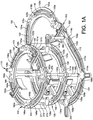
- FIG. 1A is an isometric view of a circular fixator 100 according to some embodiments of this disclosure.
- FIG. 1B shows the circulator fixator 100 with the patient's foot fixed by wires 412, following the procedures.
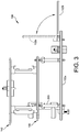
- FIGS. 2 and 3 show plan and side elevation views of the circular fixator 100.
- the circular fixator 100 is a device comprising a plurality of rings 102, 130 and 142.
- one ring 102 of the plurality of rings is elongated.
- the elongated ring 102 has a proximal portion 102a and a distal portion 102b.
- the elongated ring 102 is configured so that the distal portion 102b can be rigidly attached to the first portion 102a in a first position parallel to or coplanar with the proximal portion 102a.
- the distal portion 102b can be rigidly attached to the first portion 102a in a second position having a non-zero angle with respect to the proximal portion.
- the non-zero angle is 90 degrees.
- the plurality of rings include first and second circular rings 142, 130 adapted to be positioned around a leg of a patient during fixation, and the first ring 142 is greater in diameter than the second ring 130 and 102.
- This configuration permits the surgeon to maintain a constant distance.
- the clearance between the inner diameter of each ring and the nearest leg tissue is about two fingers' breadth (e.g., about 3.7 cm to about 4 cm), at different heights along the patient's leg.
- the fixator is adapted for use on another extremity, a similar clearance between the inner diameter of each ring and the nearest tissue is used.
- the top ring 142 is correspondingly greater in inner diameter than the middle ring 130. Because the ring 130 is smaller, it reduces the moment arm for pins or wires.
- the top ring 142 has an inner diameter of about 18 cm
- the middle ring 130 has an inner diameter of about 16 cm. This is just one example, and any combination of ring sizes can be used to accommodate the geometry of any given patient's calf.
- Each ring 102, 130 and 142 has a first (e.g., top) face, a second (e.g., bottom) face, and at least one slot.
- ring 102 has slots 104, 110, 116, 122;
- ring 130 has four slots, including slots 132, 138;
- ring 142 has slots 144, 150, 154, and 160.
- Each slot is defined by first and second interior edges of its respective ring 102, 130 and 142 on opposing sides of the slot.
- Each slot (e.g., 104) penetrates from the first face of the ring (e.g., 102) to the second face.
- each ring e.g., 102
- the first (e.g., top) face of each ring has a first scallop-shaped recess (e.g., 106a) adjacent the slot 104 on the first edge and a second scallop-shaped recess (e.g., 106b) adjacent the slot 104 on the second edge.
- the slot 104 terminates at an opening 108a, 108b at each respective end of the slot.
- the openings 108a, 108b have a dimension that is substantially greater than a width of the slot 106.
- slot 110 has scallop-shaped recesses 112a, 112b and end openings 114a, 114b; slot 116 has recesses 118a, 118b and end openings 120a, 120b; slot 122 has recesses 124a, 124b and end openings 126a, 126b; slot 132 has recesses 134a, 134b and end openings 136a, 136b; slot 138 has recesses 140a, 140b and end openings 141a, 141b; slot 144 has recesses 146a, 146b and end openings 148a, 148b; slot 150 has recesses 151a, 151b and end openings 152a, 152b; and slot 160 has recesses 162a, 162b and end openings 164a, 164b.
- one or more of the rings include recess pockets.
- the circular fixator includes at least one ring 102 having scallop shaped recesses 106a, 106b, 112a, 112b, 118a, 118b, and at least one ring having recess pockets.
- the rings without the scallops may permit the fixation device 300 to move toward the wire more quickly without any chance of becoming caught in a scallop.
- the recesses without scallops allow the surgeon to fix the fixation device 300 anywhere along the length of the slots, and the surgeon is not limited to any discrete set of fixed locations.
- the device further includes a plurality of posts 270 joining each one of the plurality of rings 130, 142 to an adjacent one of the plurality of rings.
- the center ring 130 is connected to the top ring 142 by fixed posts 270, and the center ring 130 is connected to the bottom ring 102 by a plurality of calibrated struts 260.
- the calibrated struts permit accurate and even adjustments to the distance between the bottom ring 102 and the center ring 130 (e.g., for compression/distraction of the foot or height adjustments to the desired height).
- all of the posts 270 are of the same fixed type. In some embodiments, as shown in FIG.
- one or more of the posts 270 can be replaced by suitably configured plates 271, threaded rods, spacers, or struts.
- the plates 271 can each have a respective vertical slot 272.
- Each slot 272 has openings 273 at the top and bottom of the slot.
- the slots 272 can have the same width as the slots 112a, 112b, and the openings 273 can have the same size as the openings 114a, 114b.
- the slots 272 of the plates 271 can receive fixations elements 330, and the openings 273 can receive plugs 170, for pre- loading the fixation elements 330, in the manner described below.
- any combination of posts 270, plates 271, rods, spacers and/or struts can be used.
- each scallop-shaped recess (e.g., 112a, 112b) comprises a plurality of curved arcs, and each curved arc subtends an angle in a range from about 10 degrees to 170 degrees.
- the subtended angle is in a range from 30 degrees to 150 degrees.
- the subtended angle is in a range from 30 degrees to 150 degrees.
- the subtended angle is in a range from 60 degrees to about 120 degrees.
- each scallop-shaped recess comprises a plurality of circular arcs, each circular arc subtending an angle of about 90 degrees.
- the rings 102, 130, 142 comprise a metal, such as aluminum or titanium.
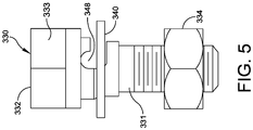
- At least one of the fixation devices 300 comprises a bolt 330, a nut 334 and a washer 340.
- the bolt 330 has head 332 and a threaded portion 331 sized to fit through the slot (e.g., 112a, 112b).
- the bolt 330 includes a side slot 348 in a side surface of the threaded portion 331, for receiving a wire 412.
- the washer 340 is shaped to fit a respective one of the curved arcs on the scallop-shaped recess 114a, 114b on each side of the slot 110 of the ring 102.
- the washer 340 has a textured gripping surface 346 for securely positioning the wire.
- the washer 340 has two curved edges 343 adapted for fitting the curved arcs of the scallop shaped recesses. The remaining two edges of the washer can be flat.
- the gripping surface can have ridges, barbs, splines, slots, a knurled surface, or the like.
- the opening (e.g., 114a, 114b) at each end of each slot (e.g., 112a, 112b) is adapted to receive a nut 334 of a fixation device 330 through the opening.
- the slot (e.g., 112a, 112b) is adapted to receive a threaded portion 331 of the fixation device 330 through the slot, but the slot has a width that is smaller than a dimension of the nut 334.
- the fixation device 330 can be inserted into the openings (e.g., 114a, 114b) but cannot fall out of the slots.
- the fixation devices can be pre-assembled, and the pre-assembled fixation devices can pre-loaded onto the slots prior to surgery.
- the openings (e.g., 114a, 114b) can be then be plugged to prevent release of the fixation devices 330.
- Some embodiments further comprise at least one post having a threaded body portion adapted to fit through the slot (e.g., 110) of the ring 102.
- the post has a longitudinal slot through the post (and parallel to the longitudinal axis of the post) for receiving a bolt of the fixation device 300.
- the surgeon can also insert rods into the bone using the circulator fixator 100.
- a pin cube 351 can be mounted in the slot (e.g., 154) for fixing the pin (also referred to as a rod).
- International Application Publication WO2015/167581 entitled “CIRCULAR FIXATOR SYSTEM AND METHOD,” published on November 5, 2015, can be usefully consulted in this regard.
- a wire tensioner 400 can be coupled to a wire 412 extending from a first fixation device 330a and/or a second fixation device 330b.
- the wire 412 extends through a side slot 348 of the fixation device 330a, 330b and can be loosely and/or firmly held by a washer 340.
- the wire 412 is inserted through an opening (see FIG. 7B ) in a wire tensioner tip 402.
- an actuation mechanism 406 of the wire tensioner 400 defines a wire slot 410 extending from a first end 408a to a second end 408b.
- the wire 412 extends at least partially into the wire slot 410.
- a handle portion 404 includes a first handle 404a and a second handle 404b that can be squeezed (or otherwise actuated) to apply tension to the wire 412 extending through the wire tensioner tip 402.
- the handles 404a, 404b can be actuated to apply a predetermined amount of tension to the wire 412 corresponding to a selected movement and/or selected position of at least one bone.
- the wire tensioner 400 can include an indicator 414 configured to provide a visual indication regarding the amount of tension applied to the wire 412.
- the wire tensioner 400 can include a locking bar 416 to lock the wire tensioner 400 at a selected tension.
- the wire tensioner 400 applies tension to a wire 412 after the wire 412 is passed through the patient.
- the wire 412 is initially coupled to a first fixation device 330a and/or a second fixation device 330b.
- One of the fixation devices, such as the second fixation device 330b is tightened to anchor (or fix) a first end of the wire 412.
- the second fixation device, such as the first fixation device 330a is partially tightened to maintain the wire 412 within the side slot 348 while still allowing some movement of the wire 412 within the side slot 348.
- the tensioner 400 is coupled to a second end of the wire 412 extending from the first fixation device 330a.
- a selected tension is applied to the wire 412 by the tensioner 400 and the first fixation device 330a is further tightened to fix the wire 412 at the selected tension.
- the tensioner 400 can be released from the wire 412 after tightening the first and/or second fixation devices 330a, 330b.
- a wire tensioner may include a cylinder configured to be coupled to a wire tensioner tip 402 and rotated to apply tension to a wire 412 inserted through the wire tensioner tip 402.
- handles, rotatable cylinders, and/or any other suitable elements can be configured to apply tension to wire 412 inserted through a wire tensioning tip 402.
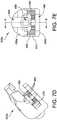
- FIGS. 7A-7G illustrates a wire tensioner tip 402a configured to be coupled to a wire tensioner 400, in accordance with some embodiments.
- the wire tensioner tip 402a includes a body 450 extending from a proximal (or rear) surface 452 to a distal (or front) surface 454.
- the body 450 includes a first (or upper) extension 456a and a second (or lower) extension 456b.
- the first and second extensions 456a, 456b are spaced apart by a ring slot 470.
- the first extension 456a includes a curved (or arced) outer surface 458a and a flat inner surface 458b.
- the flat inner surface 458b is configured to abut a first surface of a ring, such as ring 142.
- the second extension 456b includes a flat outer surface 460a and a spaced apart flat inner surface 460b.
- the flat inner surface 460b is configured to abut a second surface of a ring, such as ring 142.
- the ring slot 470 is sized and configured to receive a ring of the circular fixator 100 therein, such as ring 142.
- the slot 470 can have a width equal to and/or greater than the thickness of the ring 142.
- the first and second extensions 456a, 456b each have a length related to the width of the ring 142.
- the upper extension 456a has a length X1 sufficient to extend from a first edge 180a of a ring 142a to a second edge 180b and the lower extension 456b has a length X2 sufficient to extend from the first edge 180a of the ring 142a to a first side 182a of a slot 144 defined by the ring 142a (see FIG. 8 ).
- the upper extension 456a and/or the lower extension 456b can define any suitable lengths X1, X2.
- the upper extension 456a defines a visualization cutout 460 extending from the outer surface 458a to the inner surface 458b.
- the visualization cutout 460 can be sized and configured to allow visualization of a fixation device 330, as described in greater detail below.
- the visualization cutout 460 is positioned within the upper extension 456a such that at least a portion of the visualization cutout 460 overlaps a slot 144 defined in the ring 142a when the ring 142a is inserted into the ring slot 470.
- a coupling extension 464 extends from the proximal surface 452 of the body 450.
- the coupling extension 464 includes a centrally located circular boss 466.
- the circular boss 466 and the body 402 define a continuous channel 468 extending therethrough substantially along a horizontal axis.
- the channel 468 is sized and configured to receive the wire 412 therethrough, as discussed in greater detail below.
- the coupling extension 464 is configured to couple the wire tensioner tip 402a to the wire tensioner 400.
- wire tensioner tip 402a having a coupling extension 464 can be coupled to the wire tensioner 400 using any suitable mechanism and/or can be formed integrally with the wire tensioner 400.
- the coupling extension 464 can be positioned on and extend from the wire tensioner 400 and the wire tensioning tip 402a can include a cavity or other element configured to receive the coupling extension 464 therein.
- the wire tensioner tip 402a includes a pivoting engagement body 474 positioned between the first extension 456a and the second extension 456b.
- the pivoting engagement body 474 is positioned at least partially within the ring slot 470 and is configured to abut an edge (or outer surface) 180a of a ring 142a when the ring 142a is positioned within the ring slot 470.
- the pivoting engagement body 474 includes a body 476 defining a first hole 478 extending therethrough.
- the hole 478 is sized and configured to receive a pin 480 and/or other rotational coupling device therein.
- a ring-facing surface 482 of the body 476 includes a plurality of projections 484 (e.g., teeth, diamond teeth, knurls, etc.) configured to abut an outer surface 180a of the ring 142a.
- the pivoting engagement body 474 is configured to pivot about the pin 480 such that the ring-facing surface 482 (and by extension the plurality of projections 484) can be aligned at an angle with respect to a horizontal axis of the wire tensioner tip 402a.
- the pivoting engagement body 474 can pivot a predetermined angle in one of a first and/or a second direction with respect to the horizontal axis of the wire tensioner tip 402.
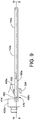
- FIGS. 8-10B illustrate the wire tensioner tip 402a coupled to a ring 142a of a circular fixator 100 in a straight engagement, in accordance with some embodiments.
- the ring 142a is positioned within the ring slot 470 between the first extension 456a and the second extension 456b.
- An outer surface 180a of the ring 142a abuts a pivoting engagement body 474 (see FIG. 9 ).
- the wire tensioner tip 402a provides stabilization and counter-force when tensioning a wire 412 during a surgical procedure.
- the first extension 456a is configured to extend over a bolt 332 of a fixation device 330.
- the first extension 456a can include a bolt cutout 484 extending from the inner surface 458b into the first extension 456a.
- the bolt cutout 484 is sized and configured to receive a head of the bolt 332 therein.
- the inner surface 458b of the first extensions 456a is positioned above the bolt 332 when the wire tensioner tip 402a is coupled to the ring 142a.
- the nut 334 of the fixation device 330 is configured to extend at least partially below the second extension 456b of the wire tensioner tip 402a such that the nut 334 can be tightened without removing the wire tensioner tip 402a.
- the second extension 456b defines a cutout 486 sized and configured to receive a nut 334 and a socket (not shown) therein.
- the wire tensioner tip 402a is engaged with the ring 142a in a straight engagement such that the pivoting engagement body 474 is not-offset (i.e., is perpendicular with) a horizontal axis of the wire tensioner tip 402a.
- the horizontal axis of the wire tensioner tip 402a is aligned with a radius R of the ring 142a.
- the ring-facing surface 482 of the pivoting engagement body 474 is engaged with the outer surface 180a of the ring 142a.
- the plurality of teeth 484 create a frictional force with respect to the ring 142a and prevent movement (such as slippage, camming, etc.) of the wire tensioner 400 during tensioning of a wire 412.
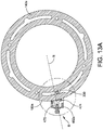
- FIGS. 11-13B illustrate the wire tensioner tip 402a coupled to a ring 142a of a circular fixator 100 in an angled engagement, in accordance with some embodiments.
- the pivoting engagement body 474 is offset (i.e., at a non-perpendicular angle) with respect to the horizontal axis of the wire tensioner tip 402a.
- the horizontal axis of the wire tensioner tip 402a is also offset with respect to a radius of the ring 142a.
- the ring-facing surface 482a of the pivoting engagement body 474 is engaged with the outer surface 180a of the ring 142a.
- the pivoting engagement body 474 is offset from the body 450 of the wire tensioner tip 402a but maintains alignment and engagement with the outer surface 180a of the ring 142a. By maintaining alignment and engagement with the outer surface 180a, the pivoting engagement body 474 prevents movement of the wire tensioner 400 when in an offset (or angled) engagement.
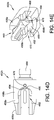
- FIGS. 14A-14G illustrate a wire tensioner tip 402b configured to be coupled to a wire tensioner 400, in accordance with some embodiments.
- the wire tensioner tip 402b is similar to the wire tensioner tip 402a discussed above in conjunction with FIGS. 7A-13B , and similar description is not repeated herein.
- the wire tensioner tip 402b includes a fixed engagement body 490 having a plurality of protrusions 494, 496a, 496b extending therefrom.
- the fixed engagement body 490 replaces the pivoting engagement body 474 of the wire tensioner tip 402a.
- the fixed engagement body 490 includes a generally rectangular body 492 defining a threaded hole 478 extending therethrough.
- the threaded hole 478 is configured to receive a ball plunger configured to couple to an additional and/or alternative tensioner tip extender (not shown).
- the fixed engagement body 490 includes a central protrusion 494 extending from the rectangular body 492.
- the central protrusion 494 extends a predetermined distance into the ring slot 470.
- the central protrusion 494 is sized and configured to be received within a notch 186 defined by a first edge 180a of a ring 142b.
- the central protrusion 494 maintains the wire tensioner tip 402b when the wire tensioner tip 402 is engaged with the ring 142b in a straight engagement, as discussed in greater detail below.
- the fixed engagement body 490 includes a first side protrusion 496a and a second side protrusion 496b extending from the rectangular body 492.
- the first side protrusion 496a and the second side protrusion 496b can be symmetrically disposed at either end of the rectangular body 492.
- the first side protrusion 496a and the second side protrusion 496b extend a predetermined distance from rectangular body 492.
- first side protrusion 496a and the second side protrusion 496b each extend a length equal to the length of the center protrusion 494, although it will be appreciated that each of the center protrusion 494, the first side protrusion 496a, and/or the second side protrusion 496b can extend a greater and/or lesser length.
- the first side protrusion 496a and the second side protrusion 496b are sized and configured to be received within notches 186 defined by the first edge 180a of the ring 142b, as discussed in greater detail below with respect to FIG. 16B .
- one or more of the protrusions 494, 496a, 496b can be omitted and/or additional protrusions can be added.
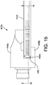
- FIGS. 15-16B illustrate the wire tensioner tip 402b coupled to a ring 142b in a straight engagement, in accordance with some embodiments.
- the ring 142b is at least partially inserted into the ring slot 470 the wire tensioner tip 402b.
- a first edge 180a of the ring 142b abuts the fixed engagement body 490.
- the outer edge 180a of the ring 142b defines a plurality of notches 186.
- the protrusions 494, 496a, 496b extending from the fixed engagement body 490 are sized and configured to be received within one of the plurality of notches 186.
- the central protrusion 494 is positioned within a notch 186.
- the central protrusion 494 and the notch 186 prevent movement (lateral movement, rotational movement, etc.) of the wire tensioner tip 402b during tensioning of a wire 412.
- the outer side protrusions 496a, 496b are not engaged with the ring 142b due to the curvature of the ring 142b.
- FIGS. 17-18B illustrate the wire tensioner tip 402b coupled to the ring 142b in an angled engagement, in accordance with some embodiments.
- the horizontal axis of the wire tensioner tip 402b is offset with respect to a radius of the ring 142b.
- a first side protrusion 496a is engaged with a notch 186 defined in the first surface 180a of the ring 142b.
- the central protrusion 494 is also engaged with a notch 186.
- the first side protrusion 496a, the central protrusion 494, and the notch 186 prevent movement (lateral movement, rotational movement, etc.) of the wire tensioner tip 402b during tensioning of a wire 412.
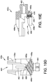
- FIGS. 19A-19E illustrate a wire tensioner tip 402c configured to be coupled to a wire tensioner 400, in accordance with some embodiments.
- the wire tensioner tip 402c is similar to the wire tensioner tip 402b discussed above in conjunction with FIGS. 14A-18B , and similar description is not repeated herein.
- the fixed engagement body 490a of the wire tensioner tip 402c includes a triangular body 492a having an apex 498 centrally positioned with respect to the wire tensioner tip 402c.
- a central protrusion 494 extends from the apex 498 of the triangular body 492a.
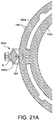
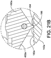
- FIGS. 20-21B illustrate the wire tensioner tip 402c coupled to a ring 142b in a straight engagement, in accordance with some embodiments.
- the ring 142b is at least partially inserted into the ring slot 470 the wire tensioner tip 402c.
- the central protrusion 494 is positioned within a notch 186.
- the central protrusion 494 and the notch 186 prevent movement (lateral movement, rotational movement, etc.) of the wire tensioner tip 402c during tensioning of a wire 412.
- the outer side protrusions 496a, 496b are not engaged with the ring 142b in a straight engagement.
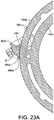
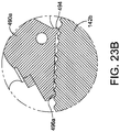
- FIGS. 22-23B illustrate the wire tensioner tip 402c coupled to the ring 142b in an angled engagement, in accordance with some embodiments.
- the horizontal axis of the wire tensioner tip 402c and the fixed engagement body 490a are offset with respect to a radius of the ring 142b.
- a first side protrusion 496a is engaged with a notch 186 defined in the first surface 180a of the ring 142b.
- the first side protrusion 496a and the notch 186 prevent movement (lateral movement, rotational movement, etc.) of the wire tensioner tip 402b during tensioning of a wire 412.
- the central protrusion 494 is not engaged with a notch, although it will be appreciated that the central protrusion 494 can be partially engaged with a notch when the angle between the horizontal axis of the wire tensioner tip 402c and the radius of the ring 142a is reduced.
Landscapes
- Health & Medical Sciences (AREA)
- Orthopedic Medicine & Surgery (AREA)
- Life Sciences & Earth Sciences (AREA)
- Surgery (AREA)
- Medical Informatics (AREA)
- Engineering & Computer Science (AREA)
- Biomedical Technology (AREA)
- Heart & Thoracic Surgery (AREA)
- Nuclear Medicine, Radiotherapy & Molecular Imaging (AREA)
- Molecular Biology (AREA)
- Animal Behavior & Ethology (AREA)
- General Health & Medical Sciences (AREA)
- Public Health (AREA)
- Veterinary Medicine (AREA)
- Surgical Instruments (AREA)
- Wire Bonding (AREA)
Priority Applications (1)
| Application Number | Priority Date | Filing Date | Title |
|---|---|---|---|
| EP21172206.1A EP3878388A1 (de) | 2017-10-25 | 2018-10-23 | Drahtspannerspitze |
Applications Claiming Priority (2)
| Application Number | Priority Date | Filing Date | Title |
|---|---|---|---|
| US201762576872P | 2017-10-25 | 2017-10-25 | |
| US16/152,650 US10959766B2 (en) | 2017-10-25 | 2018-10-05 | Wire tensioner tip |
Related Child Applications (2)
| Application Number | Title | Priority Date | Filing Date |
|---|---|---|---|
| EP21172206.1A Division-Into EP3878388A1 (de) | 2017-10-25 | 2018-10-23 | Drahtspannerspitze |
| EP21172206.1A Division EP3878388A1 (de) | 2017-10-25 | 2018-10-23 | Drahtspannerspitze |
Publications (2)
| Publication Number | Publication Date |
|---|---|
| EP3476342A1 true EP3476342A1 (de) | 2019-05-01 |
| EP3476342B1 EP3476342B1 (de) | 2021-07-07 |
Family
ID=63965314
Family Applications (2)
| Application Number | Title | Priority Date | Filing Date |
|---|---|---|---|
| EP21172206.1A Withdrawn EP3878388A1 (de) | 2017-10-25 | 2018-10-23 | Drahtspannerspitze |
| EP18201912.5A Active EP3476342B1 (de) | 2017-10-25 | 2018-10-23 | Drahtspannerspitze |
Family Applications Before (1)
| Application Number | Title | Priority Date | Filing Date |
|---|---|---|---|
| EP21172206.1A Withdrawn EP3878388A1 (de) | 2017-10-25 | 2018-10-23 | Drahtspannerspitze |
Country Status (4)
| Country | Link |
|---|---|
| US (3) | US10959766B2 (de) |
| EP (2) | EP3878388A1 (de) |
| AU (2) | AU2018247285B2 (de) |
| CA (1) | CA3020973C (de) |
Families Citing this family (6)
| Publication number | Priority date | Publication date | Assignee | Title |
|---|---|---|---|---|
| US10959766B2 (en) * | 2017-10-25 | 2021-03-30 | Wright Medical Technology, Inc. | Wire tensioner tip |
| US11291486B2 (en) * | 2018-06-19 | 2022-04-05 | Orthex, LLC | Half pins for external fixators |
| US11197692B2 (en) * | 2018-10-24 | 2021-12-14 | Glw, Inc. | External fixation stabilizers, systems, kits, and methods |
| US11266454B2 (en) * | 2019-04-03 | 2022-03-08 | New Standard Device, LLC | Wire tensioner with swivel hinge |
| US11864798B2 (en) * | 2019-09-30 | 2024-01-09 | Gitlin LLC | Y-frame external bone fixator |
| CN114052876A (zh) * | 2020-08-03 | 2022-02-18 | 北京骨外固定技术研究所 | 一种外固定器的制作方法及一种t型弧形板外固定器 |
Citations (3)
| Publication number | Priority date | Publication date | Assignee | Title |
|---|---|---|---|---|
| US5057113A (en) * | 1989-04-03 | 1991-10-15 | Citieffe S.R.L. | Device for tensioning traction wires in orthopedic surgery |
| US5431659A (en) * | 1993-08-17 | 1995-07-11 | Texas Scottish Rite Hospital For Children | Pneumatic wire tensioner |
| WO2015167581A1 (en) | 2014-05-02 | 2015-11-05 | Wright Medical Technology, Inc. | Circular fixator system and method |
Family Cites Families (19)
| Publication number | Priority date | Publication date | Assignee | Title |
|---|---|---|---|---|
| US2291413A (en) * | 1941-06-13 | 1942-07-28 | John R Siebrandt | Bone clamping and wire adjusting means |
| SU594974A1 (ru) | 1976-10-12 | 1978-02-28 | Воронежский Политехнический Институт | Устройство дл нат жени спиц |
| ATE105698T1 (de) | 1989-10-31 | 1994-06-15 | Fischer Juergen | Vorrichtung zum fixieren eines knochens. |
| US5372597A (en) * | 1993-05-12 | 1994-12-13 | Smith & Nephew Richards, Inc. | Supination-pronation device |
| US5451225A (en) * | 1993-06-10 | 1995-09-19 | Texas Scottish Rite Hospital For Crippled Children | Fastener for external fixation device wires and pins |
| US5961496A (en) * | 1997-06-17 | 1999-10-05 | Novo Nordisk A/S | Syringe with tiltable nut for quick piston disengagement |
| US6482208B1 (en) * | 1998-11-25 | 2002-11-19 | Alliance Orthopedic, Inc. | Fracture reduction clamp |
| US7306601B2 (en) * | 2005-06-10 | 2007-12-11 | Quantum Medical Concepts, Inc. | External fixation system with provisional brace |
| US8617185B2 (en) * | 2007-02-13 | 2013-12-31 | P Tech, Llc. | Fixation device |
| ES2595369T3 (es) * | 2009-03-10 | 2016-12-29 | Stryker European Holdings I, Llc | Sistema de fijación externa |
| US9107720B2 (en) * | 2009-06-02 | 2015-08-18 | Kinamed, Inc. | Surgical cable tensioning system |
| US9023045B2 (en) * | 2010-10-28 | 2015-05-05 | Stryker Trauma Sa | Bolt and tool with anti-torque features |
| US8585703B2 (en) * | 2010-12-09 | 2013-11-19 | Stryker Trauma Sa | Adjustment tool for external fixator |
| US9017339B2 (en) * | 2012-04-26 | 2015-04-28 | Stryker Trauma Gmbh | Measurement device for external fixation frame |
| US9757153B2 (en) * | 2012-09-06 | 2017-09-12 | Wright Medical Technology, Inc. | External fixator |
| US9936975B2 (en) | 2014-09-09 | 2018-04-10 | Integra Lifesciences Corporation | External fixation system |
| US9445841B2 (en) | 2014-12-10 | 2016-09-20 | Texas Scottish Rite Hospital For Children | Wire tensioner tip for use with wire fixation bolt |
| US10499972B2 (en) * | 2017-01-03 | 2019-12-10 | DePuy Synthes Products, Inc. | Mini cable tensioner for orthopedic cable tensioning |
| US10959766B2 (en) * | 2017-10-25 | 2021-03-30 | Wright Medical Technology, Inc. | Wire tensioner tip |
-
2018
- 2018-10-05 US US16/152,650 patent/US10959766B2/en active Active
- 2018-10-11 AU AU2018247285A patent/AU2018247285B2/en not_active Ceased
- 2018-10-16 CA CA3020973A patent/CA3020973C/en active Active
- 2018-10-23 EP EP21172206.1A patent/EP3878388A1/de not_active Withdrawn
- 2018-10-23 EP EP18201912.5A patent/EP3476342B1/de active Active
-
2020
- 2020-01-24 AU AU2020200558A patent/AU2020200558B2/en not_active Ceased
-
2021
- 2021-03-01 US US17/188,078 patent/US11918266B2/en active Active
-
2024
- 2024-01-29 US US18/424,949 patent/US20240206935A1/en active Pending
Patent Citations (3)
| Publication number | Priority date | Publication date | Assignee | Title |
|---|---|---|---|---|
| US5057113A (en) * | 1989-04-03 | 1991-10-15 | Citieffe S.R.L. | Device for tensioning traction wires in orthopedic surgery |
| US5431659A (en) * | 1993-08-17 | 1995-07-11 | Texas Scottish Rite Hospital For Children | Pneumatic wire tensioner |
| WO2015167581A1 (en) | 2014-05-02 | 2015-11-05 | Wright Medical Technology, Inc. | Circular fixator system and method |
Also Published As
| Publication number | Publication date |
|---|---|
| US20240206935A1 (en) | 2024-06-27 |
| AU2018247285B2 (en) | 2019-12-12 |
| AU2018247285A1 (en) | 2019-05-09 |
| US10959766B2 (en) | 2021-03-30 |
| US20190119064A1 (en) | 2019-04-25 |
| CA3020973C (en) | 2021-07-13 |
| CA3020973A1 (en) | 2019-04-25 |
| AU2020200558A1 (en) | 2020-02-13 |
| EP3476342B1 (de) | 2021-07-07 |
| EP3878388A1 (de) | 2021-09-15 |
| US11918266B2 (en) | 2024-03-05 |
| AU2020200558B2 (en) | 2021-03-04 |
| US20210177478A1 (en) | 2021-06-17 |
Similar Documents
| Publication | Publication Date | Title |
|---|---|---|
| EP3476342B1 (de) | Drahtspannerspitze | |
| US20240032977A1 (en) | Bone fixation system, assembly, implants, devices, alignment guides, and methods of use | |
| US7887537B2 (en) | External fixation system | |
| US8372123B2 (en) | Sternal closure device and method of using same | |
| CN102821709B (zh) | 骨固定系统 | |
| US7048735B2 (en) | External fixation system | |
| US9289252B2 (en) | Orthopaedic plate and spreader apparatuses and methods | |
| US20180289402A1 (en) | Bone stabilization systems | |
| JP2021171652A (ja) | 骨の配列調整及び接合の準備のためのデバイス及び方法 | |
| CN107647899B (zh) | 用于膝关节置换手术的截骨装置 | |
| US20150359580A1 (en) | Alignment guide apparatus, method and system | |
| US10010321B2 (en) | Adjustable forceps for osteosynthesis clip | |
| BR112015011072B1 (pt) | Dispositivo de fixação óssea e membro de travamento para dispositivo de fixação óssea | |
| EP2948072A2 (de) | Deckel für implantate und implantatanordnungen | |
| US20250312077A1 (en) | Apparatuses and methods for correcting bone deformities | |
| EP1383436B1 (de) | Osteosynthesevorrichtung | |
| WO2014056058A1 (pt) | Alongador diafisário e metafisário | |
| US12035928B2 (en) | Devices and methods for correction of hip deformities | |
| WO2014105742A1 (en) | Orthopedic bone plate and locking tab apparatus and method of use | |
| KR20240165050A (ko) | 골절합용 판 및 골절합용 판 장착장치 및 후족부 정렬장치 |
Legal Events
| Date | Code | Title | Description |
|---|---|---|---|
| PUAI | Public reference made under article 153(3) epc to a published international application that has entered the european phase |
Free format text: ORIGINAL CODE: 0009012 |
|
| STAA | Information on the status of an ep patent application or granted ep patent |
Free format text: STATUS: THE APPLICATION HAS BEEN PUBLISHED |
|
| AK | Designated contracting states |
Kind code of ref document: A1 Designated state(s): AL AT BE BG CH CY CZ DE DK EE ES FI FR GB GR HR HU IE IS IT LI LT LU LV MC MK MT NL NO PL PT RO RS SE SI SK SM TR |
|
| AX | Request for extension of the european patent |
Extension state: BA ME |
|
| STAA | Information on the status of an ep patent application or granted ep patent |
Free format text: STATUS: REQUEST FOR EXAMINATION WAS MADE |
|
| 17P | Request for examination filed |
Effective date: 20191030 |
|
| RBV | Designated contracting states (corrected) |
Designated state(s): AL AT BE BG CH CY CZ DE DK EE ES FI FR GB GR HR HU IE IS IT LI LT LU LV MC MK MT NL NO PL PT RO RS SE SI SK SM TR |
|
| GRAP | Despatch of communication of intention to grant a patent |
Free format text: ORIGINAL CODE: EPIDOSNIGR1 |
|
| STAA | Information on the status of an ep patent application or granted ep patent |
Free format text: STATUS: GRANT OF PATENT IS INTENDED |
|
| RIC1 | Information provided on ipc code assigned before grant |
Ipc: A61B 17/88 20060101AFI20210212BHEP Ipc: A61B 17/62 20060101ALN20210212BHEP |
|
| INTG | Intention to grant announced |
Effective date: 20210309 |
|
| GRAS | Grant fee paid |
Free format text: ORIGINAL CODE: EPIDOSNIGR3 |
|
| GRAA | (expected) grant |
Free format text: ORIGINAL CODE: 0009210 |
|
| STAA | Information on the status of an ep patent application or granted ep patent |
Free format text: STATUS: THE PATENT HAS BEEN GRANTED |
|
| AK | Designated contracting states |
Kind code of ref document: B1 Designated state(s): AL AT BE BG CH CY CZ DE DK EE ES FI FR GB GR HR HU IE IS IT LI LT LU LV MC MK MT NL NO PL PT RO RS SE SI SK SM TR |
|
| REG | Reference to a national code |
Ref country code: GB Ref legal event code: FG4D |
|
| REG | Reference to a national code |
Ref country code: AT Ref legal event code: REF Ref document number: 1407808 Country of ref document: AT Kind code of ref document: T Effective date: 20210715 |
|
| REG | Reference to a national code |
Ref country code: DE Ref legal event code: R096 Ref document number: 602018019621 Country of ref document: DE |
|
| REG | Reference to a national code |
Ref country code: IE Ref legal event code: FG4D |
|
| REG | Reference to a national code |
Ref country code: LT Ref legal event code: MG9D |
|
| REG | Reference to a national code |
Ref country code: NL Ref legal event code: MP Effective date: 20210707 |
|
| REG | Reference to a national code |
Ref country code: AT Ref legal event code: MK05 Ref document number: 1407808 Country of ref document: AT Kind code of ref document: T Effective date: 20210707 |
|
| PG25 | Lapsed in a contracting state [announced via postgrant information from national office to epo] |
Ref country code: SE Free format text: LAPSE BECAUSE OF FAILURE TO SUBMIT A TRANSLATION OF THE DESCRIPTION OR TO PAY THE FEE WITHIN THE PRESCRIBED TIME-LIMIT Effective date: 20210707 Ref country code: RS Free format text: LAPSE BECAUSE OF FAILURE TO SUBMIT A TRANSLATION OF THE DESCRIPTION OR TO PAY THE FEE WITHIN THE PRESCRIBED TIME-LIMIT Effective date: 20210707 Ref country code: HR Free format text: LAPSE BECAUSE OF FAILURE TO SUBMIT A TRANSLATION OF THE DESCRIPTION OR TO PAY THE FEE WITHIN THE PRESCRIBED TIME-LIMIT Effective date: 20210707 Ref country code: FI Free format text: LAPSE BECAUSE OF FAILURE TO SUBMIT A TRANSLATION OF THE DESCRIPTION OR TO PAY THE FEE WITHIN THE PRESCRIBED TIME-LIMIT Effective date: 20210707 Ref country code: ES Free format text: LAPSE BECAUSE OF FAILURE TO SUBMIT A TRANSLATION OF THE DESCRIPTION OR TO PAY THE FEE WITHIN THE PRESCRIBED TIME-LIMIT Effective date: 20210707 Ref country code: LT Free format text: LAPSE BECAUSE OF FAILURE TO SUBMIT A TRANSLATION OF THE DESCRIPTION OR TO PAY THE FEE WITHIN THE PRESCRIBED TIME-LIMIT Effective date: 20210707 Ref country code: AT Free format text: LAPSE BECAUSE OF FAILURE TO SUBMIT A TRANSLATION OF THE DESCRIPTION OR TO PAY THE FEE WITHIN THE PRESCRIBED TIME-LIMIT Effective date: 20210707 Ref country code: BG Free format text: LAPSE BECAUSE OF FAILURE TO SUBMIT A TRANSLATION OF THE DESCRIPTION OR TO PAY THE FEE WITHIN THE PRESCRIBED TIME-LIMIT Effective date: 20211007 Ref country code: PT Free format text: LAPSE BECAUSE OF FAILURE TO SUBMIT A TRANSLATION OF THE DESCRIPTION OR TO PAY THE FEE WITHIN THE PRESCRIBED TIME-LIMIT Effective date: 20211108 Ref country code: NO Free format text: LAPSE BECAUSE OF FAILURE TO SUBMIT A TRANSLATION OF THE DESCRIPTION OR TO PAY THE FEE WITHIN THE PRESCRIBED TIME-LIMIT Effective date: 20211007 Ref country code: NL Free format text: LAPSE BECAUSE OF FAILURE TO SUBMIT A TRANSLATION OF THE DESCRIPTION OR TO PAY THE FEE WITHIN THE PRESCRIBED TIME-LIMIT Effective date: 20210707 |
|
| PG25 | Lapsed in a contracting state [announced via postgrant information from national office to epo] |
Ref country code: PL Free format text: LAPSE BECAUSE OF FAILURE TO SUBMIT A TRANSLATION OF THE DESCRIPTION OR TO PAY THE FEE WITHIN THE PRESCRIBED TIME-LIMIT Effective date: 20210707 Ref country code: LV Free format text: LAPSE BECAUSE OF FAILURE TO SUBMIT A TRANSLATION OF THE DESCRIPTION OR TO PAY THE FEE WITHIN THE PRESCRIBED TIME-LIMIT Effective date: 20210707 Ref country code: GR Free format text: LAPSE BECAUSE OF FAILURE TO SUBMIT A TRANSLATION OF THE DESCRIPTION OR TO PAY THE FEE WITHIN THE PRESCRIBED TIME-LIMIT Effective date: 20211008 |
|
| REG | Reference to a national code |
Ref country code: DE Ref legal event code: R097 Ref document number: 602018019621 Country of ref document: DE |
|
| PG25 | Lapsed in a contracting state [announced via postgrant information from national office to epo] |
Ref country code: DK Free format text: LAPSE BECAUSE OF FAILURE TO SUBMIT A TRANSLATION OF THE DESCRIPTION OR TO PAY THE FEE WITHIN THE PRESCRIBED TIME-LIMIT Effective date: 20210707 |
|
| PLBE | No opposition filed within time limit |
Free format text: ORIGINAL CODE: 0009261 |
|
| STAA | Information on the status of an ep patent application or granted ep patent |
Free format text: STATUS: NO OPPOSITION FILED WITHIN TIME LIMIT |
|
| REG | Reference to a national code |
Ref country code: CH Ref legal event code: PL |
|
| PG25 | Lapsed in a contracting state [announced via postgrant information from national office to epo] |
Ref country code: SM Free format text: LAPSE BECAUSE OF FAILURE TO SUBMIT A TRANSLATION OF THE DESCRIPTION OR TO PAY THE FEE WITHIN THE PRESCRIBED TIME-LIMIT Effective date: 20210707 Ref country code: SK Free format text: LAPSE BECAUSE OF FAILURE TO SUBMIT A TRANSLATION OF THE DESCRIPTION OR TO PAY THE FEE WITHIN THE PRESCRIBED TIME-LIMIT Effective date: 20210707 Ref country code: RO Free format text: LAPSE BECAUSE OF FAILURE TO SUBMIT A TRANSLATION OF THE DESCRIPTION OR TO PAY THE FEE WITHIN THE PRESCRIBED TIME-LIMIT Effective date: 20210707 Ref country code: EE Free format text: LAPSE BECAUSE OF FAILURE TO SUBMIT A TRANSLATION OF THE DESCRIPTION OR TO PAY THE FEE WITHIN THE PRESCRIBED TIME-LIMIT Effective date: 20210707 Ref country code: CZ Free format text: LAPSE BECAUSE OF FAILURE TO SUBMIT A TRANSLATION OF THE DESCRIPTION OR TO PAY THE FEE WITHIN THE PRESCRIBED TIME-LIMIT Effective date: 20210707 Ref country code: AL Free format text: LAPSE BECAUSE OF FAILURE TO SUBMIT A TRANSLATION OF THE DESCRIPTION OR TO PAY THE FEE WITHIN THE PRESCRIBED TIME-LIMIT Effective date: 20210707 |
|
| 26N | No opposition filed |
Effective date: 20220408 |
|
| REG | Reference to a national code |
Ref country code: BE Ref legal event code: MM Effective date: 20211031 |
|
| PG25 | Lapsed in a contracting state [announced via postgrant information from national office to epo] |
Ref country code: MC Free format text: LAPSE BECAUSE OF FAILURE TO SUBMIT A TRANSLATION OF THE DESCRIPTION OR TO PAY THE FEE WITHIN THE PRESCRIBED TIME-LIMIT Effective date: 20210707 |
|
| PG25 | Lapsed in a contracting state [announced via postgrant information from national office to epo] |
Ref country code: LU Free format text: LAPSE BECAUSE OF NON-PAYMENT OF DUE FEES Effective date: 20211023 Ref country code: BE Free format text: LAPSE BECAUSE OF NON-PAYMENT OF DUE FEES Effective date: 20211031 |
|
| PG25 | Lapsed in a contracting state [announced via postgrant information from national office to epo] |
Ref country code: LI Free format text: LAPSE BECAUSE OF NON-PAYMENT OF DUE FEES Effective date: 20211031 Ref country code: CH Free format text: LAPSE BECAUSE OF NON-PAYMENT OF DUE FEES Effective date: 20211031 |
|
| PG25 | Lapsed in a contracting state [announced via postgrant information from national office to epo] |
Ref country code: IE Free format text: LAPSE BECAUSE OF NON-PAYMENT OF DUE FEES Effective date: 20211023 |
|
| PGFP | Annual fee paid to national office [announced via postgrant information from national office to epo] |
Ref country code: GB Payment date: 20220901 Year of fee payment: 5 |
|
| PGFP | Annual fee paid to national office [announced via postgrant information from national office to epo] |
Ref country code: FR Payment date: 20220908 Year of fee payment: 5 |
|
| PGFP | Annual fee paid to national office [announced via postgrant information from national office to epo] |
Ref country code: IT Payment date: 20220913 Year of fee payment: 5 Ref country code: DE Payment date: 20220831 Year of fee payment: 5 |
|
| P01 | Opt-out of the competence of the unified patent court (upc) registered |
Effective date: 20230515 |
|
| PG25 | Lapsed in a contracting state [announced via postgrant information from national office to epo] |
Ref country code: CY Free format text: LAPSE BECAUSE OF FAILURE TO SUBMIT A TRANSLATION OF THE DESCRIPTION OR TO PAY THE FEE WITHIN THE PRESCRIBED TIME-LIMIT Effective date: 20210707 |
|
| PG25 | Lapsed in a contracting state [announced via postgrant information from national office to epo] |
Ref country code: HU Free format text: LAPSE BECAUSE OF FAILURE TO SUBMIT A TRANSLATION OF THE DESCRIPTION OR TO PAY THE FEE WITHIN THE PRESCRIBED TIME-LIMIT; INVALID AB INITIO Effective date: 20181023 |
|
| PG25 | Lapsed in a contracting state [announced via postgrant information from national office to epo] |
Ref country code: MK Free format text: LAPSE BECAUSE OF FAILURE TO SUBMIT A TRANSLATION OF THE DESCRIPTION OR TO PAY THE FEE WITHIN THE PRESCRIBED TIME-LIMIT Effective date: 20210707 |
|
| REG | Reference to a national code |
Ref country code: DE Ref legal event code: R119 Ref document number: 602018019621 Country of ref document: DE |
|
| GBPC | Gb: european patent ceased through non-payment of renewal fee |
Effective date: 20231023 |
|
| PG25 | Lapsed in a contracting state [announced via postgrant information from national office to epo] |
Ref country code: GB Free format text: LAPSE BECAUSE OF NON-PAYMENT OF DUE FEES Effective date: 20231023 |
|
| PG25 | Lapsed in a contracting state [announced via postgrant information from national office to epo] |
Ref country code: GB Free format text: LAPSE BECAUSE OF NON-PAYMENT OF DUE FEES Effective date: 20231023 Ref country code: FR Free format text: LAPSE BECAUSE OF NON-PAYMENT OF DUE FEES Effective date: 20231031 Ref country code: DE Free format text: LAPSE BECAUSE OF NON-PAYMENT OF DUE FEES Effective date: 20240501 |
|
| PG25 | Lapsed in a contracting state [announced via postgrant information from national office to epo] |
Ref country code: MT Free format text: LAPSE BECAUSE OF FAILURE TO SUBMIT A TRANSLATION OF THE DESCRIPTION OR TO PAY THE FEE WITHIN THE PRESCRIBED TIME-LIMIT Effective date: 20210707 |
|
| PG25 | Lapsed in a contracting state [announced via postgrant information from national office to epo] |
Ref country code: IT Free format text: LAPSE BECAUSE OF NON-PAYMENT OF DUE FEES Effective date: 20231023 |
|
| PG25 | Lapsed in a contracting state [announced via postgrant information from national office to epo] |
Ref country code: IT Free format text: LAPSE BECAUSE OF NON-PAYMENT OF DUE FEES Effective date: 20231023 |
|
| PG25 | Lapsed in a contracting state [announced via postgrant information from national office to epo] |
Ref country code: TR Free format text: LAPSE BECAUSE OF FAILURE TO SUBMIT A TRANSLATION OF THE DESCRIPTION OR TO PAY THE FEE WITHIN THE PRESCRIBED TIME-LIMIT Effective date: 20210707 |