EP3476355A2 - Medizinische armanordnung - Google Patents
Medizinische armanordnung Download PDFInfo
- Publication number
- EP3476355A2 EP3476355A2 EP18818970.8A EP18818970A EP3476355A2 EP 3476355 A2 EP3476355 A2 EP 3476355A2 EP 18818970 A EP18818970 A EP 18818970A EP 3476355 A2 EP3476355 A2 EP 3476355A2
- Authority
- EP
- European Patent Office
- Prior art keywords
- link
- rotation axis
- remote
- joint
- arm
- Prior art date
- Legal status (The legal status is an assumption and is not a legal conclusion. Google has not performed a legal analysis and makes no representation as to the accuracy of the status listed.)
- Granted
Links
Images



Classifications
-
- B—PERFORMING OPERATIONS; TRANSPORTING
- B25—HAND TOOLS; PORTABLE POWER-DRIVEN TOOLS; MANIPULATORS
- B25J—MANIPULATORS; CHAMBERS PROVIDED WITH MANIPULATION DEVICES
- B25J9/00—Program-controlled manipulators
- B25J9/10—Program-controlled manipulators characterised by positioning means for manipulator elements
- B25J9/106—Program-controlled manipulators characterised by positioning means for manipulator elements with articulated links
- B25J9/1065—Program-controlled manipulators characterised by positioning means for manipulator elements with articulated links with parallelograms
-
- A—HUMAN NECESSITIES
- A61—MEDICAL OR VETERINARY SCIENCE; HYGIENE
- A61B—DIAGNOSIS; SURGERY; IDENTIFICATION
- A61B34/00—Computer-aided surgery; Manipulators or robots specially adapted for use in surgery
- A61B34/30—Surgical robots
-
- A—HUMAN NECESSITIES
- A61—MEDICAL OR VETERINARY SCIENCE; HYGIENE
- A61B—DIAGNOSIS; SURGERY; IDENTIFICATION
- A61B34/00—Computer-aided surgery; Manipulators or robots specially adapted for use in surgery
- A61B34/70—Manipulators specially adapted for use in surgery
-
- B—PERFORMING OPERATIONS; TRANSPORTING
- B25—HAND TOOLS; PORTABLE POWER-DRIVEN TOOLS; MANIPULATORS
- B25J—MANIPULATORS; CHAMBERS PROVIDED WITH MANIPULATION DEVICES
- B25J19/00—Accessories fitted to manipulators, e.g. for monitoring, for viewing; Safety devices combined with or specially adapted for use in connection with manipulators
- B25J19/0008—Balancing devices
- B25J19/002—Balancing devices using counterweights
-
- B—PERFORMING OPERATIONS; TRANSPORTING
- B25—HAND TOOLS; PORTABLE POWER-DRIVEN TOOLS; MANIPULATORS
- B25J—MANIPULATORS; CHAMBERS PROVIDED WITH MANIPULATION DEVICES
- B25J9/00—Program-controlled manipulators
- B25J9/06—Program-controlled manipulators characterised by multi-articulated arms
-
- A—HUMAN NECESSITIES
- A61—MEDICAL OR VETERINARY SCIENCE; HYGIENE
- A61B—DIAGNOSIS; SURGERY; IDENTIFICATION
- A61B17/00—Surgical instruments, devices or methods
- A61B2017/00367—Details of actuation of instruments, e.g. relations between pushing buttons, or the like, and activation of the tool, working tip, or the like
- A61B2017/00398—Details of actuation of instruments, e.g. relations between pushing buttons, or the like, and activation of the tool, working tip, or the like using powered actuators, e.g. stepper motors, solenoids
-
- A—HUMAN NECESSITIES
- A61—MEDICAL OR VETERINARY SCIENCE; HYGIENE
- A61B—DIAGNOSIS; SURGERY; IDENTIFICATION
- A61B17/00—Surgical instruments, devices or methods
- A61B2017/00477—Coupling
-
- A—HUMAN NECESSITIES
- A61—MEDICAL OR VETERINARY SCIENCE; HYGIENE
- A61B—DIAGNOSIS; SURGERY; IDENTIFICATION
- A61B90/00—Instruments, implements or accessories specially adapted for surgery or diagnosis and not covered by any of the groups A61B1/00 - A61B50/00, e.g. for luxation treatment or for protecting wound edges
- A61B90/50—Supports for surgical instruments, e.g. articulated arms
- A61B2090/506—Supports for surgical instruments, e.g. articulated arms using a parallelogram linkage, e.g. panthograph
-
- A—HUMAN NECESSITIES
- A61—MEDICAL OR VETERINARY SCIENCE; HYGIENE
- A61B—DIAGNOSIS; SURGERY; IDENTIFICATION
- A61B90/00—Instruments, implements or accessories specially adapted for surgery or diagnosis and not covered by any of the groups A61B1/00 - A61B50/00, e.g. for luxation treatment or for protecting wound edges
- A61B90/50—Supports for surgical instruments, e.g. articulated arms
Definitions
- the present disclosure relates to a medical arm assembly.
- the present disclosure relates to a medical arm assembly configured to manipulate a medical tool.
- a medical robot has a robot arm configured to operate a medical tool such as a surgical tool or an endoscope.
- a medical tool is mounted on the fore-end of the robot arm, and the tool also moves in accordance with the movement of the robot arm, so that an operation can be performed.
- the robot arm includes a plurality of links configured to be movable relative to each other.
- the plurality of links may be connected through joints such as hinges.
- One of two links connected to each other by a joint is movable relative to the other.
- the robot arm includes a motor that provides a driving force such that the multiple links are movable relative to each other.
- Embodiments of the present disclosure provide technology by which the position of the above-mentioned remote point can easily be changed and fixed to a desired position.
- a medical arm assembly includes: a remote joint in which a remote point spaced apart from a reference point is located; a positioning arm section configured to support the remote joint and move the remote joint such that the relative position of the remote point with respect to the reference point is changed in a forward-and-rearward direction and an upward-and-downward direction, the positioning arm section being configured to fix the relative position of the remote point with respect to the reference point; an operating arm section connected to the remote joint, the operating arm section being configured to fix a surgery tool thereto and rotate the surgery tool about a remote rotation axis passing through the remote point in a left-and-right direction, the operating arm section being configured to move the surgery tool in a direction that is perpendicular to the remote rotation axis and that passes through the remote point; and an arm supporting section to which the positioning arm section and the operating arm section are connected to be supported, the reference point being located in the arm supporting section.
- the medical arm assembly may further include a platform supporting the arm supporting section.
- the positioning arm section may include a first positioning motor and a second positioning motor configured to provide driving force so as to change the relative position of the remote point.
- the first positioning motor and the second positioning motor may be configured to operate independently from each other.
- the operating arm section may include an ending link slidably supported on the remote joint, and the positioning arm section may include a guide link connected to the remote joint.
- the ending link may be configured to be rotatable about the remote rotation axis and to be movable in a direction that is perpendicular to the remote rotation axis and that passes through the remote point.
- the remote joint may include a sliding part configured to slidably support the ending link, and a hinge part configured to rotatably connect the guide link to the sliding part.
- the operating arm section may include an ending link slidably supported on the remote joint; a middle link connected to the ending link so as to be rotatable about a rotation axis parallel to the remote rotation axis; and a starting link connected to the middle link so as to be rotatable about a rotation axis parallel to the remote rotation axis, and connected to the arm supporting section so as to be rotatable about a rotation axis parallel to the remote rotation axis.
- the operating arm section may include: a first counterweight configured to provide a gravity load such that a connection point of the starting link with the middle link is lifted upwards; and a second counterweight configured to provide a gravity load such that a connection point of the middle link with the ending link is lifted upwards.
- the operating arm section may further include a first operating motor configured to provide driving force for rotating the starting link with respect to the arm supporting section, and a second operating motor configured to provide driving force for rotating the middle link with respect to the starting link.
- the operating arm section may further include: a first link connected to the arm supporting section so as to be rotatable about a rotation axis parallel to the remote rotation axis; and a second link connected to the first link so as to be rotatable about a rotation axis parallel to the remote rotation axis, and connected to the middle link so as to be rotatable about a rotation axis parallel to the remote rotation axis.
- a connection point between the middle link and the second link may be located on an opposite side of a connection point between the middle link and the ending link.
- the positioning arm section may include: a rotating link connected to the arm supporting section so as to be rotatable about a rotation axis perpendicular to the forward-and-rearward direction; and a guide link connected to the remote joint, and connected to the rotating link so as to be movable in an extension direction of the rotating link.
- the positioning arm section may include a guide link connected to the remote joint, and a rotating link connected to the guide link so as to be rotatable about a guide rotation axis, and connected to the arm supporting section so as to be rotatable about a rotation axis parallel to the guide rotation axis.
- the positioning arm section may further include: a support link connected to the arm supporting section so as to be rotatable about a rotation axis parallel to the guide rotation axis; and a sliding link connected to the support link so as to be movable in an extension direction of the support link, and connected to the guide link so as to be rotatable about a rotation axis parallel to the guide rotation axis.
- a connection point between the guide link and the rotating link a connection point between the guide link and the sliding link may be located on an opposite side of the remote joint.
- the positioning arm section may further include: a first operating link connected to the arm supporting section so as to be rotatable about a rotation axis parallel to the guide rotation axis; and a second operating link connected to the first operating link so as to be rotatable about a rotation axis parallel to the guide rotation axis, and connected to the guide link so as to be rotatable about a rotation axis parallel to the guide rotation axis.
- a connection point between the guide link and the rotating link may be located on an opposite side of the remote joint.
- a medical tool can be operated with various motions while minimizing the size of a perforation area for surgery in the user's skin.
- Embodiments of the present disclosure are exemplified for the purpose of describing the technical idea of the present disclosure.
- the scope of the present disclosure is not limited to the embodiments illustrated below or to the detailed description of the embodiments.
- Direction-indicating terms such as "forward” used in the present disclosure indicate a direction based on the direction in which a remote point RCM is located with respect to a reference point O in FIG. 1 , and thus direction-indicating terms such as “rearward” indicate the direction opposite thereto.
- Direction-indicating terms such as “upwards” and “upper” used in the present disclosure indicate the direction in which a middle link 130 is located with respect to a reference straight line X in the accompanying drawings, and direction-indicating terms such as “downward” and “lower” indicate a direction opposite thereto.
- the reference point O, the remote point RCM, the reference straight line X, and the middle link 130 shown in the accompanying drawings may be oriented differently, and the direction-indicating terms may be interpreted accordingly.
- a medical arm assembly according to an embodiment of the present disclosure may be used as a single-port surgery robot.
- single-port surgery refers to a surgical operation in which a medical tool is inserted through a single perforation site of a patient, and the perforation site may be an incision site or an existing orifice such as a mouth.
- the medical arm assembly according to an embodiment of the present disclosure may be applied to a robot that performs laryngeal surgery via the throat or a robot for an endoscope.
- FIG. 1 is a conceptual elevation illustrating some mechanism of a medical arm assembly according to an embodiment of the present disclosure.
- a platform 20, to be described later, which is connected to an arm supporting section 10 is omitted, unlike the other drawings.
- the medical arm assembly may include a remote joint J1 where a remote point RCM spaced apart from a reference point O is located.
- the remote point RCM is spaced apart forward from the reference point O.
- the reference point O means a virtual point disposed at a fixed position of the medical arm assembly.
- the remote point RCM is a virtual point located in the remote joint J1 and moves together with the remote joint J1 when the remote joint J1 moves.
- the remote point RCM may be referred to as a "remote center” or a "RCM(Remote Center of Motion)".
- the medical arm assembly may include a positioning arm section 200 configured to support the remote joint J1.
- the positioning arm section 200 may be supported by the arm supporting section 10 to be described later.
- the positioning arm section 200 may include a guide link 216, one end of which is connected to the remote joint J1.
- the guide link 216 may be connected to a hinge part J1a of the remote joint J1.
- the positioning arm section 200 may be configured to move the remote joints J1 such that the relative position of the remote point RCM with respect to the reference point O is changed in the direction of a virtual reference straight line X passing through the reference point O and the remote point RCM.
- the positioning arm section 200 may be configured to move the remote joints J1 such that the relative position of the remote point RCM with respect to the reference point O is changed in the direction of a virtual vertical straight line Y perpendicular to the reference straight line X.
- the reference straight line X direction is a forward-and-rearward direction
- the vertical straight line Y direction is an upward-and-downward direction.
- the positioning arm section 200 may be configured to move the remote joint J1 such that the relative position of the remote point RCM with respect to the reference point O is changed in the forward-and-rearward direction and the upward-and-downward direction.
- the guide link 216 of the positioning arm section 200 is connected to a rotating link 211 so as to be slidable, and the rotating link 211 may be supported to be rotatable around a rotation axis extending in the left-and-right direction.
- the "left-and-right direction” and the “upward-and-downward direction” mean a direction perpendicular to the forward-and-rearward direction and the upward-and-downward direction.
- the guide link 216 may be slidably connected to the rotating link 211 by a joint B1, and the rotating link 211 may be rotatably connected to the arm supporting section 10, to be described later, by a joint BO. Through this, the angle and distance of the remote point RCM with respect to the reference point O can be changed.
- the positioning arm section 200 may be configured to fix the relative position of the remote point RCM with respect to the reference point O.
- the guide link 216 of the positioning arm section 200 may be fixed to the rotating link 211, and the rotating link 211 may be fixed to the arm supporting section 10 by the brake.
- the user may move the positioning arm section 200 such that the remote point RCM is disposed at a desired position on a plane formed by the reference straight line X and the vertical straight line Y, and may then fix the position of the remote point RCM using the brake.
- the positioning arm section 200 having a 2 degree of freedom (2 DOF) is operated by the joint B0 and the joint B1
- the angle and distance of the remote point RCM to the reference point O can be changed.
- the relative position of the remote point RCM can be maintained constant, when the joint B1 fixes the guide link 216 by the brake such that the guide link 216 does not slide and the joint B0 fixes the rotating link 211 by the brake such that the rotating link 211 does not rotate.
- the medical arm assembly may include an operating arm section 100 connected to the remote joint J1.
- the operating arm section 100 may be supported by the arm supporting section 10.
- the operating arm section portion 100 may be supported by the arm supporting section 10 and the remote joint J1.
- the operating arm section 100 may be configured to fix a medical tool 300 thereto.
- the medical tool may be a surgical tool or an endoscope.
- the tool 300 may also be referred to as an end effector.
- the tool 300 may be fixed to a distal end of the operating arm section 100.
- the tool 300 may be fixed to the lower end of an ending link 130 of the operating arm section 100.
- the operating arm section 100 may be configured to rotate the tool 300 around a remote rotation axis.
- the remote rotation axis means a virtual rotation axis passing through the remote point RCM in the left-and-right direction.
- the remote rotation axis is perpendicular to the reference straight line X and passes through the remote point RCM.
- rotation axis is a virtual axis for describing the present disclosure and does not mean an actual component of an apparatus.
- a shaft disposed on the rotation axis may be provided.
- a protrusion protruding along the rotation axis may be provided on one of the two components and a recess may be provided on the remaining one of the two components such that the protrusion is rotatably engaged with the recess.
- the operating arm section 100 may be configured to move the tool 300 in a direction that is perpendicular to the remote rotation axis and passes through the remote point.
- the direction that is perpendicular to the remote rotation axis and passes through the remote point may be a direction that is not parallel to the reference straight line X.
- the middle link 120 of the operating arm section 100 rotates about the joint A2
- the ending link 130 of the operating arm section 100 is moved by a sliding part J1b of the remote joint J1 in a direction perpendicular to the remote rotation axis and passing through the remote point, and the tool 300 may be moved integrally with the ending link 130.
- the wording "a first component and a second component rotate integrally” means that the first component rotates in the same rotating direction as the second component at the same rotating speed as the second component.
- the wording "a first component and a second component move integrally” means that the first component moves in the same direction as the second component at the same speed as the second component.
- the remote joint J1 may include a sliding part J1b on which the ending link 130 is slidably supported.
- the sliding part J1b may guide the ending link 130 such that the ending link 130 is slidable in a direction that is perpendicular to the remote rotation axis and passes through the remote point.
- the remote joint J1 may include a hinge part J1a that rotatably connects the guide link 216 to the sliding part J1b.
- the hinge part J1a is capable of making the ending link 130 rotatable about the remote rotation axis.
- the medical arm assembly may include counterweights W1 and W2 for balancing a gravity load.
- the medical arm assembly may include a first counterweight W1 and a second counterweight W2.
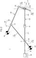
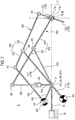
- FIG. 2 is a conceptual elevation illustrating a medical arm assembly 1 according to a first embodiment of the present disclosure.
- the description of the medical arm assembly according to the embodiment described above with reference to FIG. 1 is also applicable to a medical arm assembly 1 according to the first embodiment to be described later.
- the tool 300 is capable of performing a 2-DOF motion in the state in which the remote point RCM is fixed. Specifically, in the state in which the remote point RCM is fixed, 1) the tool 300 is rotatable about the remote rotation axis, and 2) is movable in a direction that is perpendicular to the remote rotation axis and passes through the remote point RCM.
- This 2-DOF motion may be possible in the state in which the position of the remote point RCM is fixed.
- the remote point RCM is located in a perforation site of the patient, it is possible to freely operate the tool while minimizing the perforation site.
- the tool when a 2-DOF motion that shifts the remote point RCM in the upward-and-downward direction and the forward-and-rearward direction by the positioning arm section 200 is added to the 2-DOF motion described above, the tool is capable of performing a 4-DOF motion.
- a 4-DOF motion that shifts the remote point RCM in the upward-and-downward direction and the forward-and-rearward direction by the positioning arm section 200 is added to the 2-DOF motion described above, the tool is capable of performing a 4-DOF motion.
- the assembly of the arm supporting section 10 and the operating arm section 100 in the medical arm assembly 1 includes a 2-DOF serial arm.
- the positioning arm section 200 of the medical arm assembly 1 is configured to have a brake function and to perform a 2-DOF motion.
- the brake function is capable of being performed by restricting the movement of the guide link 216 at the joint B1 and by restricting the rotation of the rotating link 211 at the joint B0.
- a joint A1, a joint A2, a joint B0, and a joint B1 are independent joints
- a joint A3 and the remote joint J1 are dependent joints.
- an "independent joint” means a joint of which the operation is directly controlled by the driving force of a motor
- a "dependent joint” means a joint, whose operation is passively operated by the operation of the independent joint.
- the medical arm assembly 1 includes an arm supporting section 10 to which the positioning arm section 200 and the operating arm section 100 are connected so as to be supported.
- the operating arm section 100 is connected to and supported by the arm supporting section 10 by the joint A1
- the positioning arm section 200 is connected to the arm supporting section 10 by the joint B0.
- the reference point O is located on the arm supporting section 10.
- the reference point O may be located in the joint A1.
- the arm supporting section 10 of the medical arm assembly 1 may be elongated along the reference straight line X.
- the joint A1 and the joint B0 may be disposed at the distal end of the arm supporting section 10 of the medical arm assembly 1.
- the rearward end of the arm supporting section 10 may be fixed to a platform 20.
- the joint A1 and the joint B0 may be connected to the forward end of the arm supporting section 10.
- the medical arm assembly 1 may include the platform 20 that supports the arm supporting section 10.
- the arm supporting section 10 may be fixed to the platform 20.
- the platform 20 may fixedly support the arm supporting section 10.
- the platform 20 is capable of supporting the arm supporting section 10 such that the platform 20 is positionally movable in at least one of the upward-and-downward direction, the forward-and-rearward direction, and the left-and-right direction.
- the operating arm section 100 of the medical arm assembly 1 includes an ending link 130 slidably supported by the remote joint J1.
- the ending link 130 is configured to be movable in a direction that is perpendicular to the remote rotation axis and passes through the remote point RCM.
- the ending link 130 may be slidably supported by the sliding part J1b of the remote joint J1.
- the ending link 130 of the medical arm assembly 1 is configured to be rotatable about the remote rotation axis.
- the ending link 130 may be rotatably supported by the hinge part J1a of the remote joint J1.
- the ending link 130 of the medical arm assembly 1 extends through the remote point RCM.
- the ending link 130 includes a lower end portion 132 and an upper end portion 131.
- the tool 300 is fixed to the lower end portion 132.
- the upper end portion 131 is connected to the joint A3.
- the operating arm section 100 of the medical arm assembly 1 includes a middle link 120 connected to the ending link 130 so as to be rotatable about a rotation axis parallel to the remote rotation axis.
- the middle link 120 is connected to the ending link 130 by the joint A3.
- the joint A3 includes a hinge having a rotation axis parallel to the remote rotation axis.
- the joint A2 is disposed in the middle link 120 of the medical arm assembly 1.
- the middle link 120 includes a forward end portion 122 and a rearward end portion 121 with respect to the joint A2.
- the forward end portion 122 of the middle link 120 is connected to the joint A3.
- the forward end portion 122 of the middle link 120 is rotatably connected to the upper end portion 131 of the ending link 130.
- the second counterweight W2 is fixed to the rearward end portion 121 of the middle link 120.
- the operating arm section 100 of the medical arm assembly 1 includes a starting link 110 connected to the middle link so as to be rotatable about a rotation axis parallel to the remote rotation axis.
- the starting link 110 is connected to the middle link 120 by the joint A2.
- the joint A2 includes a hinge having a rotation axis parallel to the remote rotation axis.
- the starting link 110 of the medical arm assembly 1 is connected to the arm supporting section 10 so as to be rotatable about a rotation axis parallel to the remote rotation axis.
- the starting link 110 is connected to the arm supporting section 10 by the joint A1.
- the joint A1 includes a hinge having a rotation axis parallel to the remote rotation axis.
- the joint A1 is disposed in the starting link 110 of the medical arm assembly 1.
- the starting link 110 includes an upper portion 112 and a lower portion 111 with respect to the joint A1.
- the upper end portion 112 of the starting link 110 is connected to the joint A2.
- the first counterweight W1 is fixed to the lower end portion 111 of the starting link 110.
- the first counterweight W1 provides a gravity load such that a connection point between the starting link 110 and the middle link 120 (the point where the joint A2 is located) is lifted upwards.
- the first counterweight W1 may be fixed to the starting link 110.
- the first counterweight W1 is disposed on an opposite side of the connection point between the starting link 110 and the middle link 120 (the point where the joint A2 is located) with respect to the connection point between the starting link 110 and the arm supporting section 10 (the point where the joint A1 is located).
- the second counterweight W2 provides a gravity load such that a connection point between the middle link 120 and the ending link 130 (the point where the joint A3 is located) is lifted upwards.
- the second counterweight W2 may be fixed to the middle link 120.
- the second counterweight W2 is disposed on an opposite side of the connection point between the middle link 120 and the ending link 130 (the point where the joint A3 is located) with respect to the connection point between the starting link 110 and the middle link 120 (the point where the joint A2 is located).
- the operating arm section 100 of the medical arm assembly 1 includes a first operating motor (not shown) that provides a driving force for rotating the starting link 110 with respect to the arm supporting section 10.
- the joint A1 is capable of rotating the starting link 110 with respect to the arm supporting section 10 by the first operating motor.
- the operating arm section 100 of the medical arm assembly 1 includes a second operating motor (not shown) that provides driving force for rotating the middle link 120 with respect to the starting link 110.
- the joint A2 is capable of rotating the middle link 120 with respect to the starting link 110 by the second operating motor.
- the positioning arm section 200 of the medical arm assembly 1 includes a guide link 216 connected to the remote joint J1.
- the guide link 216 may be connected to the hinge part J1a of the remote joint J1 at one end thereof.
- the guide link 216 of the medical arm assembly 1 is connected to the rotating link 211 to be movable in the extension direction of the rotating link 211.
- the extension direction of the rotating link 211 is changed as the angle of the rotating link 211 with respect to the arm supporting section 10 is changed.
- the guide link 216 is connected to the middle link 211 by the joint B1.
- the joint B1 includes a guide configured to guide the movement of the guide link 216 in the extension direction of the rotating link 211.
- the positioning arm section 200 of the medical arm assembly 1 includes the rotating link 211 connected to the ending link 10 so as to be rotatable about a rotation axis perpendicular to the forward-and-rearward direction.
- the rotation axis perpendicular to the forward-and-rearward direction is parallel to the remote rotation axis.
- the rotating link 211 is connected to the arm supporting section 10 by the joint B0.
- the joint B0 includes a hinge having a rotation axis perpendicular to the forward-and-rearward direction.
- the positioning arm section 200 includes a first positioning motor (not shown) and a second positioning motor (not shown) so as to provide driving force to change the relative position of the remote point RCM.
- the joint B0 is capable of rotating the starting link 211 with respect to the arm supporting section 10 by the first positioning motor.
- the joint B1 is capable of moving the guide link 216 in the extension direction of the rotating link 211 with respect to the rotating link 211 by the second positioning motor. Through this, it is possible to change the relative positions of the remote point RCM with respect to the reference point O in the upward-and-downward direction and in the forward-and-rearward direction.
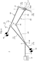
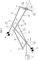
- FIG. 3 is a conceptual elevation illustrating a medical arm assembly 2 according to a second embodiment of the present disclosure.
- the positioning arm section 200 of the medical arm assembly 2 according to the second embodiment is the same as the positioning arm section 200 according to the first embodiment described above, and a description thereof will thus be omitted.
- the medical arm assembly 1 according to the second embodiment will be described, focusing on differences from the first embodiment.
- the assembly of the arm supporting section 10 and the operating arm section 100 in the medical arm assembly 2 according to the second embodiment has 2 DOF and includes five bars.
- the positioning arm section 200 of the medical arm assembly 2 is configured to have a brake function and to perform a 2-DOF motion.
- a joint A4, a joint A5, a joint B0, and a joint B1 are independent joints, and a joint A6, a joint A7, a joint A8, a joint A9, and a remote joint J1 are dependent joints.
- the joint A4, the joint A5, and the joint B0 may be disposed at the distal end of the arm supporting section 10 of the medical arm assembly 2.
- the upper end portion 131 of the ending link 130 of the medical arm assembly 2 is connected to the joint A9.
- the middle link 120 is connected to the ending link 130 by the joint A9.
- the joint A9 includes a hinge having a rotation axis parallel to the remote rotation axis.
- the joint A8 is disposed in the middle link 120 of the medical arm assembly 2.
- the middle link 120 includes a forward end portion 122 and a rearward end portion 123 with respect to the joint A8.
- the forward end portion 122 of the middle link 120 is connected to the joint A9.
- the forward end portion 122 of the middle link 120 is rotatably connected to the upper end portion 131 of the ending link 130.
- the rearward end portion 123 of the middle link 120 is connected to the joint A7.
- the rearward end portion 123 of the middle link 120 is rotatably connected to a second link 150.
- the starting link 110 of the medical arm assembly 2 is connected to the middle link 120 by the joint A8.
- the joint A8 includes a hinge having a rotation axis parallel to the remote rotation axis.
- the starting link 110 of the medical arm assembly 2 is connected to the middle link 10 by the joint A4.
- the joint A4 includes a hinge having a rotation axis parallel to the remote rotation axis.
- the joint A4 is disposed in the starting link 110 of the medical arm assembly 2.
- the starting link 110 includes an upper portion 112 and a lower portion 111 with respect to the joint A4.
- the upper end portion 112 of the starting link 110 is connected to the joint A8.
- the first counterweight W1 is fixed to the lower end portion 111 of the starting link 110.
- the operating arm section 100 of the medical arm assembly 2 further includes a first link 140 connected to the arm supporting section 10 so as to be rotatable about a rotation axis parallel to the remote rotation axis.
- the first link 140 is connected to the second link 150 so as to be rotatable about a rotation axis parallel to the remote rotation axis.
- the first link 140 of the medical arm assembly 2 is connected to the joint A5, and the other end is connected to the joint A6.
- the first link 140 is connected to the arm supporting section 10 by the joint A5.
- the joint A5 includes a hinge having a rotation axis parallel to the remote rotation axis.
- the first link 140 is connected to the second link 150 by the joint A6.
- the joint A6 includes a hinge having a rotation axis parallel to the remote rotation axis.
- the operating arm section 100 of the medical arm assembly 2 further includes a second link 150 connected to the first link 140 so as to be rotatable about a rotation axis parallel to the remote rotation axis.
- the second link 150 is connected to the middle link 120 so as to be rotatable about a rotation axis parallel to the remote rotation axis.
- the second link 150 of the medical arm assembly 2 is connected to the joint A6, and the other end is connected to the joint A7.
- the second link 150 is connected to the first link 140 by the joint A6.
- the second link 150 is connected to the middle link 120 by the joint A7.
- the joint A7 includes a hinge having a rotation axis parallel to the remote rotation axis.
- connection point between the middle link 120 and the starting link 110 of the medical arm assembly 2 (the point where the joint A8 is located)
- the connection point between the middle link 120 and the second link 150 (the point where the joint A7 is located) is located on an opposite side of the connection point between the middle link 120 and the ending link 130 (the point where the joint A9 is located).
- the joint A9 may be located at the forward side and the joint A7 may be located at the rearward side.
- the joint A6 is located behind the joint A7 and the joint A5.
- the first counterweight W1 of the medical arm assembly 2 is disposed on an opposite side of the connection point between the starting link 110 and the middle link 120 (the point where the joint A8 is located) with respect to the connection point between the starting link 110 and the arm supporting section 10 (the point where the joint A4 is located).
- the second counterweight W2 of the medical arm assembly 2 may be fixed to the joint A6.
- the second counterweight W2 may be disposed behind the joint A7.
- the joint A4 is capable of rotating the starting link 110 with respect to the arm supporting section 10 by the first operating motor (not shown) of the medical arm assembly 2.
- the joint A5 is capable of rotating the first link 140 with respect to the arm supporting section 10 by the second operating motor (not shown) of the medical arm assembly 2.
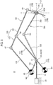
- FIG. 4 is a conceptual elevation illustrating a medical arm assembly 3 according to a third embodiment of the present disclosure.
- the operating arm section 100 of the medical arm assembly 3 according to the third embodiment is the same as the operating arm section 100 according to the first embodiment described above, and a description thereof will thus be omitted.
- the medical arm assembly 3 according to the third embodiment will be described, focusing on differences from the first embodiment.
- the assembly of the arm supporting section 10 and the operating arm section 100 in the medical arm assembly 3 includes a 2-DOF serial arm.
- the positioning arm section 200 of the medical arm assembly 3 is configured to have a brake function and to perform a 2-DOF motion.
- the brake function is capable of being performed by restricting the movement of a rotating link 220 at a joint B2 and by restricting the rotation of a guide link 230 at a joint B3.
- a joint A1, a joint A2, the joint B2, and the joint B3 are independent joints
- a joint A3 and a remote joint J1 are dependent joints. Since the joint B2 and the joint B3 of the positioning arm section 200 are configured to be independently rotatable, the relative position of the remote point RCM can be changed in the forward-and-rearward direction and the upward-and-downward direction.
- the joint A1 and the joint B2 may be disposed at the distal end of the arm supporting section 10 of the medical arm assembly 3.
- the support joint JO may be connected to the rearward end of the arm supporting section 10 of the medical arm assembly 3, and the joint A1 and the joint B2 may be connected to the forward end of the arm supporting section 10.
- the positioning arm section 200 of the medical arm assembly 3 includes a guide link 230 connected to the remote joint J1.
- the guide link 230 may be connected to the hinge part J1a of the remote joint J1 at one end thereof.
- the guide link 230 of the medical arm assembly 3 is connected to the rotating link 220 to be rotatable about a guide rotation axis.
- the guide link 230 is connected to the rotating link 220 by the joint B3.
- the joint B3 includes a hinge having the guide rotation axis.
- the guide rotation axis may extend in a direction perpendicular to the reference axis X.
- the guide rotation axis may be parallel to the remote rotation axis.
- the positioning arm section 200 of the medical arm assembly 3 includes the rotating link 220 connected to the guide link 230 so as to be rotatable about the guide rotation axis.
- the rotating link 220 is connected to the arm supporting section 10 so as to be rotatable about a rotation axis parallel to the remote rotation axis.
- the rotating link 220 is connected to the arm supporting section 10 by the joint B2.
- the joint B2 includes a hinge having a rotation axis parallel to the guide rotation axis.
- the joint B2 is capable of rotating the rotating link 220 with respect to the arm supporting section 10 by the first positioning motor of the medical arm assembly 3.
- the joint B3 is capable of rotating the guide link 230 with respect to the rotating link 220 by the second positioning motor of the medical arm assembly 3.
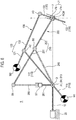
- FIG. 5 is a conceptual elevation illustrating a medical arm assembly 4 according to a fourth embodiment of the present disclosure.
- the operating arm section 100 of the medical arm assembly 3 according to the fourth embodiment is the same as the operating arm section 100 according to the second embodiment described above, and a description thereof will thus be omitted.
- the positioning arm section 200 of the medical arm assembly 4 according to the fourth embodiment is the same as the positioning arm section 200 according to the third embodiment described above, and a description thereof will thus be omitted.
- FIG. 6 is a conceptual elevation illustrating a medical arm assembly 5 according to a fifth embodiment of the present disclosure.
- the operating arm section 100 of the medical arm assembly 5 according to the fifth embodiment is the same as the operating arm section 100 according to the first embodiment described above, and a description thereof will thus be omitted.
- the medical arm assembly 5 according to the fifth embodiment will be described, focusing on differences from the third embodiment.
- the positioning arm section 200 of the medical arm assembly 5 is configured as a 2-DOF mechanism.
- the joint B7 performs a brake function and the joint B4 or the joint B13 performs a brake function so as to fix the position of the remote point RCM.
- the brake function is capable of being performed by restricting the operation of at least two of the joints B4, B5, B6, and B7 of the positioning arm section 200.
- the brake function is capable of being performed when the rotation of a rotating link 240 is restricted by the joint B4 and the movement of a sliding link 266 is restricted by the joint B7.
- a joint A1 and a joint A2 are independent joints
- a joint A3 and a remote joint J1 are dependent joints.
- two of the joints B4, B13, B5, B6, and B7 are independent joints and the remaining three are dependent joints.
- the joint B4 and the joint B7 may be independent joints, and the joint B13, the joint B5, and the joint B6 may be dependent joints that are passively operated by the independent operation of each of the joint B4 and the joint B7.
- the joint B13 and the joint B7 may be independent joints, and the joint B4, the joint B5, and the joint B6 may be dependent joints that are passively operated by the independent operation of each of the joint B13 and the joint B7.
- the joint B4 and the joint B13 may be independent joints, and the joint B5, the joint B6, and the joint B7 may be dependent joints that are passively operated by the independent operation of each of the joints B4 and B13.
- the remote point RCM becomes movable in the forward-and-rearward direction and the upward-and-downward direction.
- the positioning arm section 200 is capable of being operated by the first positioning motor and the second positioning motor of the medical arm assembly 5.
- the joint A1, the joint B4, and the joint B13 may be connected to the forward end of the arm supporting section 10 of the medical arm assembly 5.
- the rearward end of the arm supporting section 10 may be fixed to a platform 20.
- the positioning arm section 200 of the medical arm assembly 5 includes a guide link 250 connected to the remote joint J1.
- the guide link 250 may be connected to the hinge part J1a of the remote joint J1 at one end thereof.
- the guide link 250 of the medical arm assembly 5 is connected to the rotating link 240 to be rotatable about a guide rotation axis.
- the guide link 250 is connected to the rotating link 240 by the joint B5.
- the joint B5 includes a hinge having the guide rotation axis.
- the guide rotation axis may extend in a direction perpendicular to the reference axis X.
- the guide rotation axis may be parallel to the remote rotation axis.
- the guide link 250 includes a forward end portion 252 and a rearward end portion 251 with respect to the joint B5.
- the forward end portion 252 is connected to the remote joint J1.
- the rearward end portion 251 is connected to the joint B6.
- the positioning arm section 200 of the medical arm assembly 5 includes the rotating link 240 connected to the guide link 250 so as to be rotatable about the guide rotation axis.
- the rotating link 240 is connected to the arm supporting section 10 so as to be rotatable about a rotation axis parallel to the guide rotation axis.
- the rotating link 240 is connected to the arm supporting section 10 by the joint B4.
- the joint B4 includes a hinge having a rotation axis parallel to the guide rotation axis.
- the positioning link 200 of the medical arm assembly 5 further includes a sliding link 266 connected to the support link 261 to be movable in the extension direction of the support link 261.
- the extension direction of the support link 261 is changed as the angle of the support link 261 with respect to the arm supporting section 10 is changed.
- the sliding link 266 is connected to the arm supporting section 10 by the joint B7.
- the joint B7 includes a guide configured to guide the movement of the sliding link 266 in the extension direction of the support link 261.
- the sliding link 266 is connected to the guide link 250 so as to be rotatable about a rotation axis parallel to the guide rotation axis.
- the sliding link 266 is connected to the guide link 250 by the joint B6.
- the joint B6 includes a hinge having a rotation axis parallel to the guide rotation axis.
- connection point between the guide link 250 and the rotating link 240 (the point where the joint B5 is located)
- connection point between the guide link 250 and the sliding link 266 (the point where the joint B6 is located) is located on an opposite side of the remote joint J1.
- the sliding link 266 may be located behind the joint B5.
- the extension direction of the support link 261 is a direction perpendicular to the guide rotation axis.
- the positioning arm section 200 of the medical arm assembly 5 further includes a support link 261 connected to the arm supporting section 10 so as to be rotatable about a rotation axis parallel to the guide rotation axis.
- the support link 261 is connected to the arm supporting section 10 by the joint B13.
- the joint B13 includes a hinge having a rotation axis parallel to the guide rotation axis.
- FIG. 7 is a conceptual elevation illustrating a medical arm assembly 6 according to a sixth embodiment of the present disclosure.
- the operating arm section 100 of the medical arm assembly 6 according to the sixth embodiment is the same as the operating arm section 100 according to the second embodiment described above, and a description thereof will thus be omitted.
- the positioning arm section 200 of the medical arm assembly 6 according to the sixth embodiment is the same as the positioning arm section 200 according to the fifth embodiment described above, and a description thereof will thus be omitted.
- FIG. 8 is a conceptual elevation illustrating a medical arm assembly 7 according to a seventh embodiment of the present disclosure.
- the operating arm section 100 of the medical arm assembly 7 according to the seventh embodiment is the same as the operating arm section 100 according to the first embodiment described above, and a description thereof will thus be omitted.
- the medical arm assembly 7 according to the seventh embodiment will be described, focusing on differences from the third embodiment.
- the positioning arm section 200 of the medical arm assembly 7 includes four bars with 2 DOF having a brake function.
- the brake function is capable of being performed when the joint B8 of the positioning arm section 200 restricts the movement of a rotating link 270 and the joint B9 restricts the rotation of a first operating link 201.
- a joint A1 and a joint A2 are independent joints, and a joint A3 and a remote joint J1 are dependent joints.
- two of the joints B8, B9, B10, B11, and B12 are independent joints and the remaining three are dependent joints.
- the joint B8 and the joint B9 may be independent joints
- the joint B10, the joint B11, and the joint B12 may be dependent joints that are passively operated by the independent operation of each of the joint B8 and the joint B9.
- the positioning arm section 200 is capable of being operated by the first positioning motor and the second positioning motor of the medical arm assembly 5.
- the joint A1, the joint B8, and the joint B9 may be disposed at the distal end of the arm supporting section 10 of the medical arm assembly 7.
- the rearward end of the arm supporting section 10 of the medical arm assembly 7 may be fixed to the platform 20, and the joint A1, the joint B8, and the joint B9 may be connected to the forward end of the arm supporting section 10.
- the positioning arm section 200 of the medical arm assembly 7 includes a guide link 280 connected to the remote joint J1.
- the guide link 280 may be connected to the hinge part J1a of the remote joint J1 at one end thereof.
- the guide link 280 of the medical arm assembly 7 is connected to the rotating link 270 to be rotatable about a guide rotation axis.
- the guide link 280 is connected to the rotating link 270 by the joint B10.
- the joint B10 includes a hinge having the guide rotation axis.
- the guide rotation axis may extend in a direction perpendicular to the reference axis X.
- the guide rotation axis may be parallel to the remote rotation axis.
- the guide link 280 includes a forward end portion 282 and a rearward end portion 281 with respect to the joint B10.
- the forward end portion 282 is connected to the remote joint J1.
- the rearward end portion 281 is connected to the joint B11.
- the positioning arm section 200 of the medical arm assembly 7 includes the rotating link 270 connected to the guide link 280 so as to be rotatable about the guide rotation axis.
- the rotating link 270 is connected to the arm supporting section 10 so as to be rotatable about a rotation axis parallel to the guide rotation axis.
- the rotating link 270 is connected to the arm supporting section 10 by the joint B8.
- the joint B8 includes a hinge having a rotation axis parallel to the guide rotation axis.
- the positioning arm section 200 of the medical arm assembly 7 further includes a first operating link 201 connected to the arm supporting section 10 so as to be rotatable about a rotation axis parallel to the guide rotation axis.
- the first operating link 201 is connected to the arm supporting section 10 by the joint B9.
- the joint B9 includes a hinge having a rotation axis parallel to the guide rotation axis.
- the positioning arm section 200 of the medical arm assembly 7 includes a second operating link 290 connected to the first operating link 201 so as to be rotatable about a rotation axis parallel to the guide rotation axis.
- the second operating link 290 is connected to the first operating link 201 by the joint B12.
- the joint B12 includes a hinge having a rotation axis parallel to the guide rotation axis.
- the second operating link 290 is connected to a guide link 280 so as to be rotatable about a rotation axis parallel to the guide rotation axis.
- the second operating link 290 is connected to the guide link 280 by the joint B11.
- the joint B11 includes a hinge having a rotation axis parallel to the guide rotation axis.
- connection point between the guide link 280 and the rotating link 270 (the point where the joint B10 is located)
- connection point between the guide link 280 and the second operating link 290 (the point where the joint B11 is located) is located on an opposite side of the remote joint J1.
- the joint B12 is located behind the joint A11 and the joint B9.
- FIG. 9 is a conceptual elevation illustrating a medical arm assembly 8 according to an eighth embodiment of the present disclosure.
- the operating arm section 100 of the medical arm assembly 8 according to the eighth embodiment is the same as the operating arm section 100 according to the second embodiment described above, and a description thereof will thus be omitted.
- the positioning arm section 200 of the medical arm assembly 8 according to the eighth embodiment is the same as the positioning arm section 200 according to the seventh embodiment described above, and a description thereof will thus be omitted.
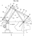
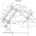
- FIGS. 10A and 10B are elevations each illustrating an operating mechanism of the medical arm assembly 8 according to the eighth embodiment of the present disclosure.
- FIGS. 10A and 10B show a distance D between the reference point O and the remote point RCM in the forward-and-rearward direction and a distance H from the ground to the remote point RCM in the upward-and-downward direction.
- the state of FIG. 10B is obtained when the positioning arm section 200 is operated so as to change from the state of FIG. 10A so that the relative position of the remote point RCM with respect to the reference point O is changed in the forward-and-rearward direction and in the upward-and-downward direction.
- FIGS. 10A and 10B show a distance D between the reference point O and the remote point RCM in the forward-and-rearward direction and a distance H from the ground to the remote point RCM in the upward-and-downward direction.
- the positioning arm section 200 is capable of fixing the relative position of the remote point RCM by the brake function.
- the ending link 130 at which the tool is fixed is capable of performing the above-mentioned 2-DOF motion by causing the operating arm section 100 and the arm supporting section to operate.
- An operation arm section 100' indicated by adding a comma (') to the reference numeral in FIGS. 10A and 10B shows, by a dotted line, an exemplary figure according to an operation of the operation arm section 100 in the fixed state of the remote point RCM.
Landscapes
- Health & Medical Sciences (AREA)
- Engineering & Computer Science (AREA)
- Surgery (AREA)
- Life Sciences & Earth Sciences (AREA)
- Robotics (AREA)
- Heart & Thoracic Surgery (AREA)
- Nuclear Medicine, Radiotherapy & Molecular Imaging (AREA)
- Biomedical Technology (AREA)
- Medical Informatics (AREA)
- Molecular Biology (AREA)
- Animal Behavior & Ethology (AREA)
- General Health & Medical Sciences (AREA)
- Public Health (AREA)
- Veterinary Medicine (AREA)
- Mechanical Engineering (AREA)
- Oral & Maxillofacial Surgery (AREA)
- Pathology (AREA)
- Manipulator (AREA)
Applications Claiming Priority (2)
| Application Number | Priority Date | Filing Date | Title |
|---|---|---|---|
| KR20170111864 | 2017-09-01 | ||
| PCT/KR2018/010180 WO2019045531A2 (ko) | 2017-09-01 | 2018-08-31 | 의료용 암 어셈블리 |
Publications (3)
| Publication Number | Publication Date |
|---|---|
| EP3476355A2 true EP3476355A2 (de) | 2019-05-01 |
| EP3476355A4 EP3476355A4 (de) | 2019-10-16 |
| EP3476355B1 EP3476355B1 (de) | 2026-04-15 |
Family
ID=65525946
Family Applications (2)
| Application Number | Title | Priority Date | Filing Date |
|---|---|---|---|
| EP18818971.6A Active EP3476356B1 (de) | 2017-09-01 | 2018-08-31 | Medizinische armanordnung |
| EP18818970.8A Active EP3476355B1 (de) | 2017-09-01 | 2018-08-31 | Medizinische armanordnung |
Family Applications Before (1)
| Application Number | Title | Priority Date | Filing Date |
|---|---|---|---|
| EP18818971.6A Active EP3476356B1 (de) | 2017-09-01 | 2018-08-31 | Medizinische armanordnung |
Country Status (6)
| Country | Link |
|---|---|
| US (2) | US11116600B2 (de) |
| EP (2) | EP3476356B1 (de) |
| JP (2) | JP6634168B2 (de) |
| KR (2) | KR102224676B1 (de) |
| CN (2) | CN109757098B (de) |
| WO (2) | WO2019045530A2 (de) |
Families Citing this family (3)
| Publication number | Priority date | Publication date | Assignee | Title |
|---|---|---|---|---|
| WO2021112193A1 (ja) * | 2019-12-05 | 2021-06-10 | 川崎重工業株式会社 | 外科手術システム及び外科手術マニピュレータアームの制御方法 |
| CN113397710A (zh) * | 2020-03-17 | 2021-09-17 | 上海奥朋医疗科技有限公司 | 适用于血管介入手术的双平面机械臂装置 |
| KR20260009959A (ko) * | 2024-07-12 | 2026-01-20 | 한국기계연구원 | 원격 중심운동 모듈 및 이를 포함하는 의료기기 |
Family Cites Families (26)
| Publication number | Priority date | Publication date | Assignee | Title |
|---|---|---|---|---|
| JP3273084B2 (ja) * | 1992-08-20 | 2002-04-08 | オリンパス光学工業株式会社 | 医療器具ホルダ装置 |
| US5397323A (en) * | 1992-10-30 | 1995-03-14 | International Business Machines Corporation | Remote center-of-motion robot for surgery |
| DE69417229T2 (de) | 1993-05-14 | 1999-07-08 | Sri International, Menlo Park, Calif. | Chirurgiegerät |
| US6594552B1 (en) * | 1999-04-07 | 2003-07-15 | Intuitive Surgical, Inc. | Grip strength with tactile feedback for robotic surgery |
| JP2000354986A (ja) | 1999-06-10 | 2000-12-26 | Sankyo Kogyo Kk | ロボットアーム |
| US9096033B2 (en) | 2007-06-13 | 2015-08-04 | Intuitive Surgical Operations, Inc. | Surgical system instrument sterile adapter |
| US9138129B2 (en) | 2007-06-13 | 2015-09-22 | Intuitive Surgical Operations, Inc. | Method and system for moving a plurality of articulated instruments in tandem back towards an entry guide |
| CN102014760B (zh) * | 2008-06-09 | 2013-11-06 | 韩商未来股份有限公司 | 手术机器人的主动接口和驱动方法 |
| GB0816324D0 (en) | 2008-09-06 | 2008-10-15 | Comis Orthopaedics Ltd | Targeting apparatus |
| CN101548904B (zh) * | 2009-05-22 | 2010-11-17 | 四川大学 | 一种手术机器人手臂 |
| KR101550451B1 (ko) * | 2010-08-10 | 2015-09-07 | (주)미래컴퍼니 | 수술용 로봇 암의 rcm 구조 |
| CN102218734B (zh) | 2011-05-31 | 2013-07-03 | 北京航空航天大学 | 具有虚拟运动中心的双平行四杆两维转动并联机构 |
| KR101307951B1 (ko) | 2012-04-25 | 2013-09-12 | 한양대학교 에리카산학협력단 | 수술용 로봇 |
| CN104334110B (zh) * | 2012-06-01 | 2017-10-03 | 直观外科手术操作公司 | 使用零空间回避操纵器臂与患者碰撞 |
| US9295524B2 (en) | 2012-06-01 | 2016-03-29 | Intuitive Surgical Operations, Inc. | Redundant axis and degree of freedom for hardware-constrained remote center robotic manipulator |
| KR101434870B1 (ko) | 2013-02-19 | 2014-09-02 | 한양대학교 에리카산학협력단 | 의료 광학 기구용 스탠드 |
| DE102013005982A1 (de) * | 2013-04-08 | 2014-10-09 | Kuka Laboratories Gmbh | Medizinroboter |
| US10353165B2 (en) | 2013-05-24 | 2019-07-16 | Koh Young Technology Inc. | Stand equipped with counterbalance unit |
| KR101740699B1 (ko) | 2013-05-24 | 2017-05-26 | 주식회사 고영테크놀러지 | 카운터 밸런스부를 구비한 스탠드 |
| WO2014204930A2 (en) * | 2013-06-17 | 2014-12-24 | Children's National Medical Center | Patient mounted mri and ct compatible robot for needle guidance in interventional procedures |
| CN104622573B (zh) | 2014-12-12 | 2017-06-09 | 北京航空航天大学 | 一种具有高刚性的四自由度远程运动中心机构 |
| KR20160122558A (ko) * | 2015-04-14 | 2016-10-24 | 한국전자통신연구원 | 모발 이식 장치 |
| WO2017077755A1 (ja) | 2015-11-04 | 2017-05-11 | ソニー株式会社 | 支持アーム装置 |
| US10912620B2 (en) | 2016-01-06 | 2021-02-09 | Vanderbilt University | Snare tool manipulator system |
| CN105832417B (zh) | 2016-01-22 | 2018-10-30 | 中国科学院重庆绿色智能技术研究院 | 一种微创手术机器人机械臂rcm机构 |
| CN106618736B (zh) | 2016-12-16 | 2019-03-08 | 微创(上海)医疗机器人有限公司 | 具有双自由度的机械臂和手术机器人 |
-
2018
- 2018-08-31 US US16/313,276 patent/US11116600B2/en active Active
- 2018-08-31 JP JP2018567049A patent/JP6634168B2/ja active Active
- 2018-08-31 JP JP2018567254A patent/JP6634169B2/ja active Active
- 2018-08-31 EP EP18818971.6A patent/EP3476356B1/de active Active
- 2018-08-31 CN CN201880002551.8A patent/CN109757098B/zh active Active
- 2018-08-31 US US16/313,290 patent/US11253336B2/en active Active
- 2018-08-31 WO PCT/KR2018/010174 patent/WO2019045530A2/ko not_active Ceased
- 2018-08-31 CN CN201880002557.5A patent/CN109788990B/zh active Active
- 2018-08-31 WO PCT/KR2018/010180 patent/WO2019045531A2/ko not_active Ceased
- 2018-08-31 EP EP18818970.8A patent/EP3476355B1/de active Active
- 2018-12-26 KR KR1020180169936A patent/KR102224676B1/ko active Active
- 2018-12-26 KR KR1020180169939A patent/KR102224681B1/ko active Active
Also Published As
| Publication number | Publication date |
|---|---|
| WO2019045531A2 (ko) | 2019-03-07 |
| US11253336B2 (en) | 2022-02-22 |
| US20210220083A1 (en) | 2021-07-22 |
| EP3476356A2 (de) | 2019-05-01 |
| KR102224676B1 (ko) | 2021-03-08 |
| CN109757098A (zh) | 2019-05-14 |
| US11116600B2 (en) | 2021-09-14 |
| KR102224681B1 (ko) | 2021-03-09 |
| WO2019045531A3 (ko) | 2019-04-18 |
| JP6634169B2 (ja) | 2020-01-22 |
| EP3476355B1 (de) | 2026-04-15 |
| WO2019045530A3 (ko) | 2019-04-18 |
| EP3476356A4 (de) | 2019-10-09 |
| EP3476356C0 (de) | 2025-08-13 |
| EP3476356B1 (de) | 2025-08-13 |
| JP2019534055A (ja) | 2019-11-28 |
| WO2019045530A2 (ko) | 2019-03-07 |
| JP2019532679A (ja) | 2019-11-14 |
| CN109788990B (zh) | 2021-11-23 |
| US20210220082A1 (en) | 2021-07-22 |
| EP3476355A4 (de) | 2019-10-16 |
| CN109757098B (zh) | 2021-07-13 |
| CN109788990A (zh) | 2019-05-21 |
| JP6634168B2 (ja) | 2020-01-22 |
| KR20200025989A (ko) | 2020-03-10 |
| KR20200025990A (ko) | 2020-03-10 |
Similar Documents
| Publication | Publication Date | Title |
|---|---|---|
| US12383359B2 (en) | Surgical master-slave robot | |
| US10939969B2 (en) | Command shaping to dampen vibrations in mode transitions | |
| CN107212922B (zh) | 硬件受限的远程中心机器人操纵器的冗余轴线和自由度 | |
| CN107049493B (zh) | 手术器械操纵器方面 | |
| KR101812297B1 (ko) | 로봇의 마스터 조작 디바이스 및 이를 구비한 수술용 로봇의 제어방법 | |
| EP3476355A2 (de) | Medizinische armanordnung | |
| EP1681029A1 (de) | Vorichtung und Verfahren zur Manipulation von medizinischen Instrumenten | |
| JP2009136538A (ja) | 眼科手術支援装置及びこれを用いた眼科手術支援システム | |
| Eugster et al. | A parallel robotic mechanism for the stabilization and guidance of an endoscope tip in laser osteotomy | |
| CN120304962A (zh) | 手术机器人系统及其控制方法 | |
| CN120304961A (zh) | 手术机器人系统的控制方法 |
Legal Events
| Date | Code | Title | Description |
|---|---|---|---|
| STAA | Information on the status of an ep patent application or granted ep patent |
Free format text: STATUS: UNKNOWN |
|
| STAA | Information on the status of an ep patent application or granted ep patent |
Free format text: STATUS: THE INTERNATIONAL PUBLICATION HAS BEEN MADE |
|
| PUAI | Public reference made under article 153(3) epc to a published international application that has entered the european phase |
Free format text: ORIGINAL CODE: 0009012 |
|
| STAA | Information on the status of an ep patent application or granted ep patent |
Free format text: STATUS: REQUEST FOR EXAMINATION WAS MADE |
|
| 17P | Request for examination filed |
Effective date: 20190124 |
|
| AK | Designated contracting states |
Kind code of ref document: A2 Designated state(s): AL AT BE BG CH CY CZ DE DK EE ES FI FR GB GR HR HU IE IS IT LI LT LU LV MC MK MT NL NO PL PT RO RS SE SI SK SM TR |
|
| AX | Request for extension of the european patent |
Extension state: BA ME |
|
| R17D | Deferred search report published (corrected) |
Effective date: 20190418 |
|
| R17P | Request for examination filed (corrected) |
Effective date: 20190124 |
|
| A4 | Supplementary search report drawn up and despatched |
Effective date: 20190916 |
|
| RIC1 | Information provided on ipc code assigned before grant |
Ipc: A61B 90/50 20160101ALI20190910BHEP Ipc: B25J 9/06 20060101ALI20190910BHEP Ipc: A61B 34/00 20160101AFI20190910BHEP Ipc: A61B 34/20 20160101ALI20190910BHEP Ipc: A61B 34/30 20160101ALI20190910BHEP |
|
| DAV | Request for validation of the european patent (deleted) | ||
| DAX | Request for extension of the european patent (deleted) | ||
| STAA | Information on the status of an ep patent application or granted ep patent |
Free format text: STATUS: EXAMINATION IS IN PROGRESS |
|
| 17Q | First examination report despatched |
Effective date: 20230320 |
|
| REG | Reference to a national code |
Ref country code: DE Ref legal event code: R079 Free format text: PREVIOUS MAIN CLASS: A61B0034000000 Ipc: B25J0009100000 Ref document number: 602018090634 Country of ref document: DE |
|
| GRAP | Despatch of communication of intention to grant a patent |
Free format text: ORIGINAL CODE: EPIDOSNIGR1 |
|
| STAA | Information on the status of an ep patent application or granted ep patent |
Free format text: STATUS: GRANT OF PATENT IS INTENDED |
|
| RIC1 | Information provided on ipc code assigned before grant |
Ipc: B25J 9/10 20060101AFI20251023BHEP Ipc: B25J 19/00 20060101ALI20251023BHEP Ipc: A61B 34/30 20160101ALI20251023BHEP Ipc: A61B 17/00 20060101ALN20251023BHEP Ipc: A61B 90/50 20160101ALN20251023BHEP |
|
| RIC1 | Information provided on ipc code assigned before grant |
Ipc: B25J 9/10 20060101AFI20251030BHEP Ipc: B25J 19/00 20060101ALI20251030BHEP Ipc: A61B 34/30 20160101ALI20251030BHEP Ipc: A61B 17/00 20060101ALN20251030BHEP Ipc: A61B 90/50 20160101ALN20251030BHEP |
|
| INTG | Intention to grant announced |
Effective date: 20251107 |
|
| RIC1 | Information provided on ipc code assigned before grant |
Ipc: B25J 9/10 20060101AFI20251031BHEP Ipc: B25J 19/00 20060101ALI20251031BHEP Ipc: A61B 34/30 20160101ALI20251031BHEP Ipc: A61B 17/00 20060101ALN20251031BHEP Ipc: A61B 90/50 20160101ALN20251031BHEP |
|
| GRAS | Grant fee paid |
Free format text: ORIGINAL CODE: EPIDOSNIGR3 |
|
| GRAA | (expected) grant |
Free format text: ORIGINAL CODE: 0009210 |
|
| STAA | Information on the status of an ep patent application or granted ep patent |
Free format text: STATUS: THE PATENT HAS BEEN GRANTED |
|
| AK | Designated contracting states |
Kind code of ref document: B1 Designated state(s): AL AT BE BG CH CY CZ DE DK EE ES FI FR GB GR HR HU IE IS IT LI LT LU LV MC MK MT NL NO PL PT RO RS SE SI SK SM TR |
|
| REG | Reference to a national code |
Ref country code: CH Ref legal event code: F10 Free format text: ST27 STATUS EVENT CODE: U-0-0-F10-F00 (AS PROVIDED BY THE NATIONAL OFFICE) Effective date: 20260415 Ref country code: GB Ref legal event code: FG4D |