EP3476365B1 - Dispositif de filtration en forme de dôme et son procédé de fabrication - Google Patents
Dispositif de filtration en forme de dôme et son procédé de fabrication Download PDFInfo
- Publication number
- EP3476365B1 EP3476365B1 EP17199058.3A EP17199058A EP3476365B1 EP 3476365 B1 EP3476365 B1 EP 3476365B1 EP 17199058 A EP17199058 A EP 17199058A EP 3476365 B1 EP3476365 B1 EP 3476365B1
- Authority
- EP
- European Patent Office
- Prior art keywords
- fabric
- sheet
- mold
- filter membrane
- support frame
- Prior art date
- Legal status (The legal status is an assumption and is not a legal conclusion. Google has not performed a legal analysis and makes no representation as to the accuracy of the status listed.)
- Active
Links
Images



Classifications
-
- A—HUMAN NECESSITIES
- A61—MEDICAL OR VETERINARY SCIENCE; HYGIENE
- A61F—FILTERS IMPLANTABLE INTO BLOOD VESSELS; PROSTHESES; DEVICES PROVIDING PATENCY TO, OR PREVENTING COLLAPSING OF, TUBULAR STRUCTURES OF THE BODY, e.g. STENTS; ORTHOPAEDIC, NURSING OR CONTRACEPTIVE DEVICES; FOMENTATION; TREATMENT OR PROTECTION OF EYES OR EARS; BANDAGES, DRESSINGS OR ABSORBENT PADS; FIRST-AID KITS
- A61F2/00—Filters implantable into blood vessels; Prostheses, i.e. artificial substitutes or replacements for parts of the body; Appliances for connecting them with the body; Devices providing patency to, or preventing collapsing of, tubular structures of the body, e.g. stents
- A61F2/01—Filters implantable into blood vessels
- A61F2/013—Distal protection devices, i.e. devices placed distally in combination with another endovascular procedure, e.g. angioplasty or stenting
-
- A—HUMAN NECESSITIES
- A61—MEDICAL OR VETERINARY SCIENCE; HYGIENE
- A61F—FILTERS IMPLANTABLE INTO BLOOD VESSELS; PROSTHESES; DEVICES PROVIDING PATENCY TO, OR PREVENTING COLLAPSING OF, TUBULAR STRUCTURES OF THE BODY, e.g. STENTS; ORTHOPAEDIC, NURSING OR CONTRACEPTIVE DEVICES; FOMENTATION; TREATMENT OR PROTECTION OF EYES OR EARS; BANDAGES, DRESSINGS OR ABSORBENT PADS; FIRST-AID KITS
- A61F2/00—Filters implantable into blood vessels; Prostheses, i.e. artificial substitutes or replacements for parts of the body; Appliances for connecting them with the body; Devices providing patency to, or preventing collapsing of, tubular structures of the body, e.g. stents
- A61F2/01—Filters implantable into blood vessels
- A61F2/0105—Open ended, i.e. legs gathered only at one side
-
- A—HUMAN NECESSITIES
- A61—MEDICAL OR VETERINARY SCIENCE; HYGIENE
- A61F—FILTERS IMPLANTABLE INTO BLOOD VESSELS; PROSTHESES; DEVICES PROVIDING PATENCY TO, OR PREVENTING COLLAPSING OF, TUBULAR STRUCTURES OF THE BODY, e.g. STENTS; ORTHOPAEDIC, NURSING OR CONTRACEPTIVE DEVICES; FOMENTATION; TREATMENT OR PROTECTION OF EYES OR EARS; BANDAGES, DRESSINGS OR ABSORBENT PADS; FIRST-AID KITS
- A61F2/00—Filters implantable into blood vessels; Prostheses, i.e. artificial substitutes or replacements for parts of the body; Appliances for connecting them with the body; Devices providing patency to, or preventing collapsing of, tubular structures of the body, e.g. stents
- A61F2/01—Filters implantable into blood vessels
-
- A—HUMAN NECESSITIES
- A61—MEDICAL OR VETERINARY SCIENCE; HYGIENE
- A61F—FILTERS IMPLANTABLE INTO BLOOD VESSELS; PROSTHESES; DEVICES PROVIDING PATENCY TO, OR PREVENTING COLLAPSING OF, TUBULAR STRUCTURES OF THE BODY, e.g. STENTS; ORTHOPAEDIC, NURSING OR CONTRACEPTIVE DEVICES; FOMENTATION; TREATMENT OR PROTECTION OF EYES OR EARS; BANDAGES, DRESSINGS OR ABSORBENT PADS; FIRST-AID KITS
- A61F2/00—Filters implantable into blood vessels; Prostheses, i.e. artificial substitutes or replacements for parts of the body; Appliances for connecting them with the body; Devices providing patency to, or preventing collapsing of, tubular structures of the body, e.g. stents
- A61F2/01—Filters implantable into blood vessels
- A61F2/0103—With centering means
-
- B—PERFORMING OPERATIONS; TRANSPORTING
- B29—WORKING OF PLASTICS; WORKING OF SUBSTANCES IN A PLASTIC STATE IN GENERAL
- B29C—SHAPING OR JOINING OF PLASTICS; SHAPING OF MATERIAL IN A PLASTIC STATE, NOT OTHERWISE PROVIDED FOR; AFTER-TREATMENT OF THE SHAPED PRODUCTS, e.g. REPAIRING
- B29C70/00—Shaping composites, i.e. plastics material comprising reinforcements, fillers or preformed parts, e.g. inserts
- B29C70/04—Shaping composites, i.e. plastics material comprising reinforcements, fillers or preformed parts, e.g. inserts comprising reinforcements only, e.g. self-reinforcing plastics
- B29C70/06—Fibrous reinforcements only
- B29C70/10—Fibrous reinforcements only characterised by the structure of fibrous reinforcements, e.g. hollow fibres
- B29C70/16—Fibrous reinforcements only characterised by the structure of fibrous reinforcements, e.g. hollow fibres using fibres of substantial or continuous length
- B29C70/22—Fibrous reinforcements only characterised by the structure of fibrous reinforcements, e.g. hollow fibres using fibres of substantial or continuous length oriented in at least two directions forming a two-dimensional [2D] structure
- B29C70/222—Fibrous reinforcements only characterised by the structure of fibrous reinforcements, e.g. hollow fibres using fibres of substantial or continuous length oriented in at least two directions forming a two-dimensional [2D] structure the structure being shaped to form a three dimensional configuration
-
- A—HUMAN NECESSITIES
- A61—MEDICAL OR VETERINARY SCIENCE; HYGIENE
- A61F—FILTERS IMPLANTABLE INTO BLOOD VESSELS; PROSTHESES; DEVICES PROVIDING PATENCY TO, OR PREVENTING COLLAPSING OF, TUBULAR STRUCTURES OF THE BODY, e.g. STENTS; ORTHOPAEDIC, NURSING OR CONTRACEPTIVE DEVICES; FOMENTATION; TREATMENT OR PROTECTION OF EYES OR EARS; BANDAGES, DRESSINGS OR ABSORBENT PADS; FIRST-AID KITS
- A61F2/00—Filters implantable into blood vessels; Prostheses, i.e. artificial substitutes or replacements for parts of the body; Appliances for connecting them with the body; Devices providing patency to, or preventing collapsing of, tubular structures of the body, e.g. stents
- A61F2/01—Filters implantable into blood vessels
- A61F2002/018—Filters implantable into blood vessels made from tubes or sheets of material, e.g. by etching or laser-cutting
-
- A—HUMAN NECESSITIES
- A61—MEDICAL OR VETERINARY SCIENCE; HYGIENE
- A61F—FILTERS IMPLANTABLE INTO BLOOD VESSELS; PROSTHESES; DEVICES PROVIDING PATENCY TO, OR PREVENTING COLLAPSING OF, TUBULAR STRUCTURES OF THE BODY, e.g. STENTS; ORTHOPAEDIC, NURSING OR CONTRACEPTIVE DEVICES; FOMENTATION; TREATMENT OR PROTECTION OF EYES OR EARS; BANDAGES, DRESSINGS OR ABSORBENT PADS; FIRST-AID KITS
- A61F2230/00—Geometry of prostheses classified in groups A61F2/00 - A61F2/26 or A61F2/82 or A61F9/00 or A61F11/00 or subgroups thereof
- A61F2230/0002—Two-dimensional shapes, e.g. cross-sections
- A61F2230/0004—Rounded shapes, e.g. with rounded corners
- A61F2230/0008—Rounded shapes, e.g. with rounded corners elliptical or oval
-
- A—HUMAN NECESSITIES
- A61—MEDICAL OR VETERINARY SCIENCE; HYGIENE
- A61F—FILTERS IMPLANTABLE INTO BLOOD VESSELS; PROSTHESES; DEVICES PROVIDING PATENCY TO, OR PREVENTING COLLAPSING OF, TUBULAR STRUCTURES OF THE BODY, e.g. STENTS; ORTHOPAEDIC, NURSING OR CONTRACEPTIVE DEVICES; FOMENTATION; TREATMENT OR PROTECTION OF EYES OR EARS; BANDAGES, DRESSINGS OR ABSORBENT PADS; FIRST-AID KITS
- A61F2240/00—Manufacturing or designing of prostheses classified in groups A61F2/00 - A61F2/26 or A61F2/82 or A61F9/00 or A61F11/00 or subgroups thereof
- A61F2240/001—Designing or manufacturing processes
-
- B—PERFORMING OPERATIONS; TRANSPORTING
- B29—WORKING OF PLASTICS; WORKING OF SUBSTANCES IN A PLASTIC STATE IN GENERAL
- B29K—INDEXING SCHEME ASSOCIATED WITH SUBCLASSES B29B, B29C OR B29D, RELATING TO MOULDING MATERIALS OR TO MATERIALS FOR MOULDS, REINFORCEMENTS, FILLERS OR PREFORMED PARTS, e.g. INSERTS
- B29K2071/00—Use of polyethers, e.g. PEEK, i.e. polyether-etherketone or PEK, i.e. polyetherketone or derivatives thereof, as moulding material
-
- B—PERFORMING OPERATIONS; TRANSPORTING
- B29—WORKING OF PLASTICS; WORKING OF SUBSTANCES IN A PLASTIC STATE IN GENERAL
- B29L—INDEXING SCHEME ASSOCIATED WITH SUBCLASS B29C, RELATING TO PARTICULAR ARTICLES
- B29L2031/00—Other particular articles
- B29L2031/14—Filters
Definitions
- This disclosure pertains in general to a dome-shaped intra-aortic filtering devices to prevent emboli from entering arteries branching from the aorta, e.g., arteries that lead to the brain.
- the disclosure relates to manufacturing of a dome-shaped intra-aortic filtering devices.
- Particles such as emboli may form, for example, as a result of the presence of particulate matter in the bloodstream.
- Particulate matter may originate from for example a blood clot occurring in the heart.
- the particulate may be a foreign body, but may also be derived from body tissues.
- atherosclerosis or hardening of the blood vessels from fatty and calcified deposits, may cause particulate emboli to form.
- clots can form on the luminal surface of the atheroma, as platelets, fibrin, red blood cells and activated clotting factors may adhere to the surface of blood vessels to form a clot.
- Blood clots or thrombi may also form in the veins of subjects who are immobilized, particularly in the legs of bedridden or other immobilized patients. These clots may then travel in the bloodstream, potentially to the arteries of the lungs, leading to a common, often-deadly disease called pulmonary embolus. Thrombus formation, and subsequent movement to form an embolus, may occur in the heart or other parts of the arterial system, causing acute reduction of blood supply and hence ischemia. The ischemia damage often leads to tissue necrosis of organs such as the kidneys, retina, bowel, heart, limbs, brain or other organs, or even death.
- emboli are typically particulate in nature
- various types of filters have been proposed in an attempt to remove or divert such particles from the bloodstream before they can cause damage to bodily tissues.
- WO 96/01591 describes a method for producing a basked shaped device from a tubular braid.
- EP 2859864 A1 describes a medical device having a concave shaped filter when expanded.
- TAVI transcatheter aortic valve implantation
- Possible areas of improvements of such devices and procedures include "windsailing" of devices with pulsatile blood flow, leakage of fluid and/or particulate matter at peripheral portions of devices during use thereof, secure positioning in a patient during use and/or retrievability, etc.
- an improved intravascular device, system and/or method would be advantageous and in particular allowing for increased flexibility, cost-effectiveness, and/or patient safety would be advantageous.
- examples of the present disclosure preferably seek to mitigate, alleviate or eliminate one or more deficiencies, disadvantages or issues in the art, such as the above-identified, singly or in any combination by providing a device, system or method according to the appended patent claims.
- the disclosure relates to a method for manufacturing an emboli filter membrane having a three-dimensional (3D) structure from a sheet of fabric made from at least of strand and a device comprising such filter membrane.
- a method of manufacturing an emboli filter having a three-dimensional (3D) structure from a sheet of fabric made from at least of strand is disclosed.
- a method of manufacturing an emboli filter having a three-dimensional (3D) structure from a sheet of fabric made from at least of strand comprises providing a mold made from two parts, a first part having a cavity in the shape of the three-dimensional structure surrounded by a first surface, a second part having a protrusion in the shape of the three-dimensional structure surrounded by a second surface. When the mold is closed there is a space between a surface of the cavity and a surface of the protruding portion.
- the method further includes arranging the sheet of fabric between the two parts of the mold so that a first portion of the sheet may be arranged between the surface of the cavity and the surface of the protruding part, and a second portion of the sheet circumference the first portion may be arranged between the first and the second surface.
- the method further includes molding the sheet of fabric by heat treatment to set the sheet of fabric and thereby obtaining the 3D-strucure.
- the method may include at least partly annihilating the second portion of the sheet during heat treatment.
- the sheet of fabric be made of polyetheretherketon (PEEK).
- PEEK polyetheretherketon
- the obtained 3D-structure be a dome shape.
- the at least one strand of the sheet at the first portion not be elongated during the heat treatment of the sheet of fabric.
- a porosity of the sheet of fabric at the first portion be the same after the heat treatment as before.
- an angle between two crossing strands of the first portion be in the range 35 to 55 degree.
- a distance between two points on a periphery of a said 3D-structure have the same distance as between the same two points over the 3D-structure.
- heating of the sheet of fabric be between 150 to 250 degrees Celsius.
- Some examples may include cooling of the fabric in the mold before the sheet is removed.
- a further aspect of the disclosure includes an embolic protection device for deployment in an aortic arch of a patient for protection of side branch vessels of the aortic arch from embolic material.
- the device comprises a filter membrane having a 3D-structure manufacture according to any of manufacturing method disclosed herein.
- the device also includes a support frame along the periphery of said 3D-structure.
- the support frame stretches the filter membrane to become substantially flat when unconstrained and the support frame is fully expanded.
- the filter membrane obtaine a pre-set 3D-structure when the support frame is constrained, such as when deployed in the aortic arch and the support frame is constrained by the interior walls of the aortic arch.
- Fig. 1A is a schematic illustration of a filter membrane 1000 having a 3-dimensional structure obtained by the disclosed manufacturing method and before being mounted on a support member.
- Fig. 1B is an exemplary picture of a filter membrane 1100 manufactured using the disclosed manufacturing method and before being mounted on a support member.
- the 3-dimensional structure may be made to cover the whole filter area of the embolic protection device. Alternatively, the 3-dimensional structure may be made to cover only a part of the embolic protection device, such as a proximal portion, a distal portion, or a central portion.
- the 3-dimensional structure has a concave inner surface and may have a convex-like outer curvature.
- the form of the 3-dimensional structure improves the adaptation of the filter membrane to the anatomy of the aortic arch and to provide a better apposition to the tissue of the aortic arch roof, encircling the plurality of the ostia of the aortic side branch vessels inside the aortic arch, covering its entrance.
- the 3-dimensional structure of the filter membrane is designed so that when deployed it should acquiring the anatomical form of the aortic arch, thus avoiding hindering the passage of catheters and devices through the aortic arch.
- the filter membrane manufactured according to the disclosure herein may be part of an embolic protection device, wherein the filter membrane is arranged to separate a first fluid volume of the aortic side branch vessels from a second fluid volume in the aortic arch when the protection unit is positioned in the aortic arch.
- the mesh of the filter membrane may be made of an elastic and atraumatic material such as a polymer.
- the obtained 3-dimensional structure may be dome-shaped, such as illustrated in figs 1A and 1B .
- the 3-dimensional structure such as a dome-shape, may have other shapes than the shape illustrated herein, it may for example, be a section of a sphere, a section of a ellipsoid, a section of a paraboloid, a section of an obloid etc.
- the filter membranes in Figs. 1A and 1B have two portions before being mounted on a support member.
- the first portion 10 of the filter membrane 1000, 1100 is obtained by the manufacturing method without significant changing the porosity factor, such as the mesh size, or change the structure of the material, such as elongation or stretching of the strands or having the strands at least partly melted. Hence the filtering performance and the flexibility, such as crimpability of the embolic protection device will not be affected.
- the obtained filter membrane 1000, 1100 has a 3-dimensional structure, such as a dome-shape, may be mounted on a support member added adjacent the periphery 12, either before the second portion 12 is removed or after.
- the mold used for obtaining the 3-dimensional structure includes two parts.
- Figs. 2A and 2B are illustrating a first part 1200 of the mold.
- Fig 2A is a top view of the first part 1200 while Fig. 2B is a section along A-A.
- the first part 1200 of the mold has a cavity 20 shaped as the 3-dimensional structure to be obtained.
- the first part of the mold 1200 has a surface 21 that circumference the cavity 20.
- the surface 21 may have pegs or holes 22a-h for attaching the sheet of fabric to for aligning the strands of the fabric to the cavity during the heat treatment.
- the pegs or holes 22a-h may additionally and/or alternatively be used for aligning the two parts of the mold. Additional and/or alternatively, in some examples, pegs and/or holes 23a-d may be used for aligning the two parts of the mold.
- Figs. 2C and 2D are illustrating a second part 1300 of the mold.
- Fig 2C is a top view of the second part 1300 while Fig. 2D is a section along A-A.
- the surface 31 may have pegs or holes 32a-h for attaching the sheet of fabric to for aligning the strands of the fabric to the cavity during the heat treatment.
- the pegs or holes 32a-h may additionally and/or alternatively be used for aligning the two parts of the mold. Additional and/or alternatively, in some examples, pegs and/or holes 33a-d may be used for aligning the two parts of the mold.
- the mold has the surface 21 that circumference the cavity 20 of the first part 1200 pegs 22a-h for alignment of the sheet of fabric, and the surface 31 of the second part 1300 that circumference the protruding portion 30 has corresponding holes, 32a-h.
- the first part 1200 of the mold holes 22a-h and the second part 1300 of the mold has corresponding pegs 31ah.
- the first part 1200 both holes and pegs 22a-h and the second part 1300 of the mold may has corresponding pegs and holes 32a-h.
- Fig. 2F is illustrating a magnification of the gap 50 between the protruding part 30 and the cavity 20.
- the distance between the first cavity 20 and the protruding portion 30 allows there to be no pressure on the part of the fabric positioned therebetween during the heat treatment. As there is no pressure applied on the fabric positioned between the cavity and the protruding portion, there will be no change in the properties or characteristics material, such as by elongating or stretching of the strands of the fabric. Further, the strands of the fabric will not be separated and the porosity factor, such as the mesh size, will be maintained.
- the portion of the sheet of fabric positioned between the cirumferencing surfaces 21, 31 may have changed properties, such as the material at this portion of the sheet being at least partly melted or at least partly annihilated, as this portion of the fabric is under pressure applied by the weight of the part of the mold arranged on top of the other.
- additional pressure is applied on the portion of the fabric arranged between the surfaces 21, 31, for example by having members forcing the two parts 1200, 1300 against each other, such as screws, pneumatic piston, weight, or any other method know to the person skilled in the art for exerting a pressure on a mold.
- the sheet is then heat treated by applying a temperature during a period of time. After the temperature has been applied, the sheet of fabric may be allowed to cool for over a period of time before being the mold is opened and the filter is removed.
- the temperature and time depends on the material.
- the temperature may be between 150 and 250 degrees Celsius, such as 190 to 210 degrees Celsius, such as 200 degrees Celsius.
- the time may range from seconds up to a couple of minutes, such as up to 1 minute, such as between 10 and 30s, such as between 15 and 25s, such as 20 to 25s.
- Fig. 3 is illustrating an example of determining the amount of fabric needed in the mold before heat-treatment.
- Fig. 3 is illustrating a piece of flat fabric 2000, such as a mesh.
- the amount of fabric is determined by calculating distances between discrete points creating enough extra material in the center when heat setting the structure the extra material left will help to result in a 3-dimensional structure, such as a dome, with no elongated or separated strands. Hence the porosity factor of the filter member will be kept and the 3-dimensional structure will be uniform.
- Fig. 4 is illustrating exemplary characteristic of a heat-treated 3D-strucuture.
- the distance x between two points along the periphery of the 3-dimensional structure should be about the same as the distance Y between the same two points over the 3-dimensional structure. This relationship makes it possible to have a 3-dimenstional structure that collapse by the support member without constraining the device it.
- a filter member or mesh may be configured from woven strands wherein the yarn orientation is at angles ⁇ that are not at right angles to the periphery or the 3-dimensional structure or a support member of an embolic protection device.
- the mesh may be aligned when arraigning the sheet of fabric in the mold so that when the filter membrane has been mounted on the support member, the weave (warp and weft) of the mesh or weave may be, for example, at angles ⁇ of 45° from a base or lateral portion of the support frame.
- the weave (warp and weft) of mesh may be at for example 30-60°, such as 35-55°, angles ⁇ from a base or lateral portion of the support frame.
- the mesh When set at a non-right angle to the support frame, the mesh may stretch, expand or contract with greater flexibility than when such weave is at right angles to the support frame. Collapsibility or crimpability of the embolic protection device is advantageously improved in this manner.
- Figs. 5A to 5D are illustrating a schematic example of an embolic protection device 1500, 1600 having a filter membrane with a 3D-structure when unconstrained 1500 and constrained 1600.
- Figs. 5A to 5C are illustrating an embolic protection device 1500 when unconstrained outside of an aortic arch.
- the embolic protection device is collapsible, such as crimpable, to be arranged in a transvascular delivery unit.
- the protection device 1500 includes a support member 40 and a filter member 41 attached to the support member 40.
- the support member 40 may be, in some examples, a complete hoop completely surrounding a periphery of the filter member 41.
- the filter member 41 may extend (partly or entirely) outside the periphery defined by support fame 40, and thereby create a collar or rim.
- the collar or rim may improve apposition with the vessel wall rough texture.
- the collar or rim may be made from a different material than the filter member 41.
- the support member 40 When the embolic protection device 1500 is unconstrained, the support member 40 will retain its original shape and the filter member 41 will become almost completely flat, ass illustrated in figs 5A to 5C .
- the support member 40 is a ring but may in some examples have a more elongated shape, such as oblong or elliptic.
- Fig. 5D is illustrating an embolic protection device 1600 where the support member 40 is slightly constrained whereby the filter member 41 strives to obtain its heat set 3-dimensional structure, such as a dome-shape.
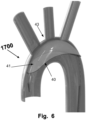
- embolic protection device 1700 makes it possible to have a support member 40 being larger than most of the prior art devices and that may self-align in the aortic arch 42 at a lower location than most of the embolic protection devices in the prior art, as illustrated in Fig. 6 . Even thou the frame member having a larger area, self-expanding 3-dimenstional structure will line the inner wall of the aortic arch above the support member. Hence the embolic protection device may span over the whole apex from the ascending aorta to the descending aorta of the aortic arch preventing emboli from entering any of the side branches. The larger filtering area will improve the f improve the filtering and provide a better sealing against the walls of the aortic arch.
- the device 1700 of the disclosure may be attached to and delivered by a transvascular delivery unit, for example as illustrated in Fig. 1B .
- the transvascular delivery unit may be, for example, a catheter or sheath, and the protection device 1700 may be attached to the transvascular delivery unit according to methods known in the art, or by a connector mechanism.
- the transvascular delivery unit may comprise a connector mechanism 20, such as a wire, rod or tube, for example, a tether, a delivery wire, or a push wire etc.
- the connector mechanism may be connected to the connection point.
- the connector mechanism may be permanently connected to the embolic protection device 1700.
- the embolic protection device 1700 may be delivered and withdrawn using the same connector mechanism. Further, the connector mechanism may be used to hold the embolic protection device 1700 in place during a medical procedure. In some examples, the connector mechanism may be detachably connected to the embolic protection device 1700.
- the distal end and/or the proximal end of the support frame may be made from a spring section.
- Each spring section may be a pre-loaded spring that function as an engine and is configured for quickly expand or open-up a collapsed or crimped embolic protection device 1700 from a collapsed state to an expanded state and for providing a radial force between the support member 40 and a wall of the aortic arch 43, when the support member 40 is in an expanded state.
- the spring sections are engines being pre-shaped open springs.
- the spring sections may have a radius wider than the embolic protection device 1700. Different radius of the opening may provide different forces.
- the force provided by the spring sections may also reduce windsailing, in most cases to none.
- the spring sections are preferably heat treated to form the spring sections and to provide spring properties.
- the spring sections are in some examples, formed as open springs and are wider than the protection device before the device is assembled.
- the landing zone is the area every guidewire will hit aortic arch.
- An improved coverage and sealing of the landing zone may help to prevent the passage of devices over (along) the protection device 1700 (through the aortic arch), for example by leading a guide wire below the protection device 1700.
- Each spring section has a bend shape, such as a shallow U-shape, or is curved.
- the support member 40 only has one spring section at either the distal or the proximal end, the rest of the support member 40 has a deeper u-shaped form. This deeper U-shaped form does not have the same springy properties as the spring section.
- the support member may have straight central sections formed between spring sections. When using straight central sections, these are substantially straight before the device is assembled. After the device is assembled, the straight central sections may bulge or obtain a curvature due to forces in the support frame from the spring sections.
- the straight central sections may function as spring engines in a longitudinal direction of the embolic protection device.
- the spring sections are heat treated to form the spring sections, while the rest of the support member is not heat treated. This will give the support ember 40 a flexibility that may further improve apposition of the embolic protection device 1700 with the aortic arch walls as it complies better with the rough texture of the vessel wall.
- some segments may be made thicker than others, for example, at the distal end of the support frame 10, the distal spring section may be thicker than the rest of the support frame, and weaker proximally. This may also make it easier to crimp the support member 40, e.g. into a catheter lumen for delivery, or for improved exiting such lumen when deploying the embolic protection device.
- both the distal and the proximal spring sections are made thicker than the rest of the support frame. This will improve the spring forces at both the proximal and the distal end.
- the thicker spring sections may open up the support frame while the thinner sections are more compliant with the vessel wall.
- both the spring sections and the central sections are made thicker than the joints or transition segment(s) between the thicker sections that may be made thinner. This will provide strong forces on all sides while avoiding the issues of making the whole support frame rigid. Making the whole support frame rigid may force the spring sections to close and not efficiently cover tortuous anatomies with the embolic protection device.
- the at least distal or proximal spring section may include a spring element.
- the spring element may in some examples be a loop or helix, a small spring or any other type of spring arranged at about the centre of each of the distal or proximal spring section. The spring element, is used for increasing the force applied by the support member 40 on the walls of the aortic arch 43.
- the spring sections 12, 13 are used for applying a force by the support frame 10 on the wall of aortic arch which may improve the sealing effect between the collapsible embolic protection device and the wall of the aortic arch, as well as provide an improved self-stabilizing effect. Additionally, the use of spring sections 12, 13 may improve the positioning and self-alignment of the device in the aortic arch.
- the connector mechanism may be attached to the support frame 10 allowing the protection device to pivot axially but not radially at the joint between the support frame and the connector mechanism, for example by attaching the connector element via the proximal loop.
- the spring element especially the proximal spring element 14, may in some examples function as a crimp element to improve the collapsibility of the embolic protection device by elongating the device longitudinally. Thereby allows to embolic protection device 1000 to be crimped into a sheath with small diameter.
- Spring elements may in some examples, for example when the spring elements are loops, be formed to either protruding outwards (relative the periphery/footprint defined by the support frame) or formed to be protruding inwards (relative the periphery/footprint defined by the support frame). Arranging or forming one or more of the spring elements to protrude inwards improves attachment of the filter member 41 to the support member 40.
- having one or more of the spring elements arranged to protrude inwards improves the contact between the support member 40 and the walls of the aortic arch 43 as there is nothing protruding or extending further than the support member 40 (smooth apposition to the aortic wall vessel tissue, further improvable by a collar mentioned herein).
- the support member 40 may be made from a wire, such as a spring wire, or being laser cut from a tube, ribbon, sheet, or flat wire, etc.
- the support member 40 may be of a single wire.
- the support member 40 is made from a twisted single wire.
- the support member 40 may be made of at least two wires being twisted, braided or knitted.
- the support member 40 may be in some examples made from joint free ring. In other examples, the support member 40 made be formed from a ring having at least one joint. A joint may be for example a fixation like a soldering, welding, or a clamp.
- the support member 40 may be shaped into an elongated shape, substantially elliptical, oblong, oval, or cone slot shaped. Alternatively, other shapes may be used, such as circular or rectangular. Because the aortic anatomy can vary between individuals, examples of the intra-aortic device of the disclosure may be shaped to adapt to a variety of aortic anatomies.
- the size of the collapsible device may be pre-sized and pre-formed to accommodate various patient groups (e.g., children and adults) or a particular aortic anatomy.
- the support member 40 may be, in some examples, substantially planar. In some examples, the support member 40 may have a width greater than the diameter of the aortic arch into which it is configured to be positioned in use, such as about 50% greater than the diameter of the aortic arch, such as 50 % greater than the cross-sectional chord of an aorta of a subject, in which the collapsible embolic protection device 1700 may be placed.
- a support member 40 may be longer than the aortic arch opening, such as about 20% longer than the arch opening, such as 20 % longer than an approximate distance between an upper wall of an ascending aorta of a subject, distal to an opening of an innominate artery, and an upper wall of a descending aorta of a subject, proximal to an opening of a left subclavian artery.
- the support member 40 By making the support member 40 wider than the diameter of the arch, such as about 50% wider, and longer than the aortic arch opening, such as about 200 longer, as defined above, the self-positioning of the device positioning about mid vessel diameter may be improved and thus improve the apposition with aortic arch walls. This will make it easier to deploy the embolic protection device and improve the sealing against the walls. It may also improve the coverage of all three side vessels, innominate (brachiocephalic) artery, left common carotid artery, or left subclavian artery) which are supplying blood to the brain.
- innominate brachiocephalic
- left common carotid artery left common carotid artery
- left subclavian artery left subclavian artery
- one or more lateral dimensions of the pores of the filter can be between about 50 ⁇ m and about 5 mm (e.g., 50 ⁇ m, 100 ⁇ m, 200 ⁇ m, 300 pm, 400 ⁇ m, 500 ⁇ m, 750 ⁇ m, 1 mm, 2 mm, 3 mm, 4 mm, or 5 mm).
- the filter may be, e.g., a mesh made from a plurality of fibers made of polymer, nylon, nitinol, or metal, or a combination thereof.
- the mesh may be made from woven fibers. Fibers may be from about 20 to 50 ⁇ m in thickness.
- the filter may be a perforated film.
- catheters or sheath may be used as part of the present disclosure.
- Any catheter or sheath known in the art to be configured for guiding medical instruments through vasculature may be used (e.g., stent installation catheter, ablation catheter, or those used for transcatheter aortic valve implantation (TAVI) or percutaneous aortic valve replacement (PAVR) procedures, e.g., as described in U.S. Patent No. 5,026,366 ).
- the device may include a pigtail catheter, which may be of size 6F or smaller (e.g., 1F, 2F, 3F, 4F, 5F, or 6F) and include a radiopaque material to facilitate tracking the progress of various elements of the device.
- Other catheters that can be used as part of the disclosure include any catheter used in procedures associated with a risk of embolism, which would benefit by including an intravascular filter as part of the procedure.
- a device of the disclosure may incorporate radiopaque elements.
- radiopaque elements can be affixed to, or incorporated into the device.
- portions of the frame, filter, or catheter may be constructed of OFT wire.
- Such wire can contain, e.g., a core of tantalum and/or platinum and an outer material of, e.g., nitinol.
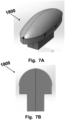
- Figs. 7A and 7B are illustrating a jig 1800 with a design to hold the 3-dimentional structures shaped filter membrane, in this case a dome shaped mesh.
- the supporting element e.g. frame is then constrained to a shape of the conferencing the base of the 3-dimensional structure and supported while applying an adhesive e.g. UV adhesive or any other kind of bonding material between the support frame and the filter membrane, while maintaining the 3-dimensional shape of the filter membrane.
- an adhesive e.g. UV adhesive or any other kind of bonding material
- any excessive material of the second portion of the filter membrane may be removed after the filter membrane has been mounted on the support frame.
- the support member will be arranged at the right position in relation to the 3-dimensional structure to make it possible for the filter membrane to return to its pre-set shape when the support frame is constrained by the walls of the aortic arch.
- the support member may be in its extended shape and the filter membrane is stretched over the support frame before an adhesive e.g. UV adhesive or any other kind of bonding material is applied between the filter membrane and the support frame.
- Fig. 8 is illustrating a chart 1900 over a method of manufacturing an emboli filter having a three-dimensional (3D) structure from a sheet of fabric made from at least of strand.
- Arranging 100 a sheet of fabric in a mold comprising two parts, a first part of a mold having a cavity in the shape of the three-dimensional structure surrounded by a first surface, and a second part having a protrusion in the shape of the three-dimensional structure surrounded by a second surface.
- the sheets may be arranged on the first part, or alternatively on the second part.
- Heat treating 102 the fabric by elevating the temperature in the mold until a set-temperature is reached. Hold the temperature at the set-temperature for a period of time. The heat will be switched of and the fabric may be allowed to cool in the mold before being removed.
- the fabric After the fabric has been removed from the device it may be mounted of a support member.
- the fabric may be mounted on the support fame while the support frame is held flat in a jig in a slightly compressed state.
- the filter membrane may be adhered to the support frame by using glue-
- the filter membrane may also be attached to the support frame using heat welding, ultrasonic welding, or stitching, etc. The skilled person would readily appreciate that there are other options known in the art for attaching a filter membrane to a support frame.
Landscapes
- Health & Medical Sciences (AREA)
- Engineering & Computer Science (AREA)
- Life Sciences & Earth Sciences (AREA)
- Animal Behavior & Ethology (AREA)
- Oral & Maxillofacial Surgery (AREA)
- Biomedical Technology (AREA)
- Heart & Thoracic Surgery (AREA)
- Vascular Medicine (AREA)
- Cardiology (AREA)
- Transplantation (AREA)
- General Health & Medical Sciences (AREA)
- Public Health (AREA)
- Veterinary Medicine (AREA)
- Textile Engineering (AREA)
- Chemical & Material Sciences (AREA)
- Composite Materials (AREA)
- Mechanical Engineering (AREA)
- Surgical Instruments (AREA)
Claims (14)
- Procédé de fabrication d'une membrane filtrante d'emboles (1000) ayant une structure tridimensionnelle à partir d'une feuille de tissu faite à partir d'au moins un brin, comprenant ;la fourniture d'un moule constitué de deux parties, une première partie (1200) ayant une cavité (20) en forme de structure tridimensionnelle entourée d'une première surface (21),une seconde partie (1300) ayant une saillie (30) ayant la forme de la structure tridimensionnelle entourée d'une seconde surface (31), et lorsque le moule est fermé, il y a un espace entre une surface de la cavité et une surface de la partie saillante ;l'agencement de la feuille de tissu entre lesdites deux parties dudit moule de sorte qu'une première partie (10) de ladite feuille soit agencée entre ladite surface de ladite cavité et ladite surface de ladite partie saillante, et qu'une seconde partie (11) de ladite circonférence de feuille de ladite première partie soit agencée entre ladite première et ladite seconde surface ;le moulage de ladite feuille de tissu par traitement thermique pour fixer ladite feuille de tissu et obtenir ainsi ladite structure 3D.
- Procédé selon la revendication 1, comprenant l'annihilation au moins partielle de ladite seconde partie de ladite feuille durant un traitement thermique.
- Procédé selon l'une quelconque des revendications 1 à 2, dans lequel ladite feuille de tissu est fabriquée en polyétheréthercétone (PEEK).
- Procédé selon l'une quelconque des revendications 1 à 3, dans lequel ladite structure 3D obtenue est une forme de dôme.
- Procédé selon l'une quelconque des revendications 1 à 4, dans lequel aucune pression n'est appliquée sur la première partie en raison de l'espace pourvu entre ladite surface de ladite cavité et ladite surface de la partie saillante dudit moule, moyennant quoi ledit au moins un brin au niveau de ladite première partie n'est pas allongé durant ledit traitement thermique de ladite feuille de tissu.
- Procédé selon l'une quelconque des revendications 1 à 5, dans lequel aucune pression n'est appliquée sur la première partie en raison de l'espace pourvu entre ladite surface de ladite cavité et ladite surface de la partie saillante dudit moule, moyennant quoi une porosité de ladite feuille de tissu au niveau de ladite première partie est la même après ledit traitement thermique qu'avant.
- Procédé selon l'une quelconque des revendications 1 à 6, dans lequel un angle entre deux brins croisés de ladite première partie est dans la plage de 35 à 55 degrés.
- Procédé selon l'une quelconque des revendications 1 à 7, dans lequel ledit moule est façonné pour fournir ladite structure 3D avec une distance entre deux points sur une périphérie d'une dite structure 3D ayant la même distance qu'entre les deux mêmes points sur la structure 3D.
- Procédé selon l'une quelconque des revendications 1 à 8, comprenant le chauffage de ladite feuille de tissu de 150 à 250 degrés Celsius.
- Procédé selon l'une quelconque des revendications 1 à 9, comprenant le refroidissement dudit tissu dans ledit moule avant d'être retiré.
- Procédé selon l'une quelconque des revendications 1 à 10, comprenant le montage de ladite structure 3D sur un cadre de support adjacent à une périphérie de ladite structure 3D après que ladite membrane filtrante a été traitée thermiquement.
- Procédé selon la revendication 11 comprenant la contrainte dudit cadre de support sur un gabarit à la forme de ladite périphérie de ladite structure 3D avant le montage de ladite membrane filtrante.
- Dispositif de protection embolique pour un déploiement dans un arc aortique d'un patient, pour une protection des vaisseaux de branche latérale de l'arc aortique d'un matériau embolique, comprenant :une membrane filtrante (1000) ayant une structure 3D préformée fabriquée selon l'une quelconque des revendications 1 à 13 ; etun cadre de support le long de la périphérie de ladite structure 3D ; etledit cadre de support conserve sa forme originale et étire ladite membrane filtrante pour qu'elle devienne sensiblement plate lorsqu'elle n'est pas contrainte.
- Dispositif selon l'une quelconque de la revendication 13, dans lequel ladite membrane filtrante obtient une structure 3D prédéfinie lorsque ledit cadre de support est contraint.
Priority Applications (12)
| Application Number | Priority Date | Filing Date | Title |
|---|---|---|---|
| EP17199058.3A EP3476365B1 (fr) | 2017-10-27 | 2017-10-27 | Dispositif de filtration en forme de dôme et son procédé de fabrication |
| EP18792943.5A EP3700463B1 (fr) | 2017-10-27 | 2018-10-26 | Dispositif de filtration en forme de dôme |
| BR112020005318-0A BR112020005318A2 (pt) | 2017-10-27 | 2018-10-26 | dispositivo de filtração com formato de abóboda e método de fabricação do mesmo |
| CN201880002235.0A CN110167484B (zh) | 2017-10-27 | 2018-10-26 | 圆顶形过滤装置及其制造方法 |
| KR1020207013573A KR20200080256A (ko) | 2017-10-27 | 2018-10-26 | 돔 형상 필터장치 및 그 제조방법 |
| AU2018356554A AU2018356554A1 (en) | 2017-10-27 | 2018-10-26 | A dome shaped filtering device and method of manufacturing the same |
| US16/302,068 US20210085445A1 (en) | 2017-10-27 | 2018-10-26 | A Dome Shaped Filtering Device and Method of Manufacturing The Same |
| JP2018566544A JP6933666B2 (ja) | 2017-10-27 | 2018-10-26 | ドーム形フィルタ装置およびその製造方法 |
| CA3084424A CA3084424A1 (fr) | 2017-10-27 | 2018-10-26 | Dispositif de filtration en forme de dome et son procede de fabrication |
| PCT/EP2018/079360 WO2019081689A1 (fr) | 2017-10-27 | 2018-10-26 | Dispositif de filtration en forme de dôme et son procédé de fabrication |
| US17/239,360 US20210236258A1 (en) | 2017-10-27 | 2021-04-23 | Dome Shaped Filtering Device and Method of Manufacturing The Same |
| JP2021134318A JP2021180943A (ja) | 2017-10-27 | 2021-08-19 | ドーム形フィルタ装置およびその製造方法 |
Applications Claiming Priority (1)
| Application Number | Priority Date | Filing Date | Title |
|---|---|---|---|
| EP17199058.3A EP3476365B1 (fr) | 2017-10-27 | 2017-10-27 | Dispositif de filtration en forme de dôme et son procédé de fabrication |
Publications (2)
| Publication Number | Publication Date |
|---|---|
| EP3476365A1 EP3476365A1 (fr) | 2019-05-01 |
| EP3476365B1 true EP3476365B1 (fr) | 2024-12-04 |
Family
ID=60191217
Family Applications (2)
| Application Number | Title | Priority Date | Filing Date |
|---|---|---|---|
| EP17199058.3A Active EP3476365B1 (fr) | 2017-10-27 | 2017-10-27 | Dispositif de filtration en forme de dôme et son procédé de fabrication |
| EP18792943.5A Active EP3700463B1 (fr) | 2017-10-27 | 2018-10-26 | Dispositif de filtration en forme de dôme |
Family Applications After (1)
| Application Number | Title | Priority Date | Filing Date |
|---|---|---|---|
| EP18792943.5A Active EP3700463B1 (fr) | 2017-10-27 | 2018-10-26 | Dispositif de filtration en forme de dôme |
Country Status (9)
| Country | Link |
|---|---|
| US (2) | US20210085445A1 (fr) |
| EP (2) | EP3476365B1 (fr) |
| JP (2) | JP6933666B2 (fr) |
| KR (1) | KR20200080256A (fr) |
| CN (1) | CN110167484B (fr) |
| AU (1) | AU2018356554A1 (fr) |
| BR (1) | BR112020005318A2 (fr) |
| CA (1) | CA3084424A1 (fr) |
| WO (1) | WO2019081689A1 (fr) |
Families Citing this family (23)
| Publication number | Priority date | Publication date | Assignee | Title |
|---|---|---|---|---|
| WO2019195860A2 (fr) | 2018-04-04 | 2019-10-10 | Vdyne, Llc | Dispositifs et procédés d'ancrage d'une valvule cardiaque transcathéter |
| US10595994B1 (en) | 2018-09-20 | 2020-03-24 | Vdyne, Llc | Side-delivered transcatheter heart valve replacement |
| US11278437B2 (en) | 2018-12-08 | 2022-03-22 | Vdyne, Inc. | Compression capable annular frames for side delivery of transcatheter heart valve replacement |
| US11071627B2 (en) | 2018-10-18 | 2021-07-27 | Vdyne, Inc. | Orthogonally delivered transcatheter heart valve frame for valve in valve prosthesis |
| US12186187B2 (en) | 2018-09-20 | 2025-01-07 | Vdyne, Inc. | Transcatheter deliverable prosthetic heart valves and methods of delivery |
| US11344413B2 (en) | 2018-09-20 | 2022-05-31 | Vdyne, Inc. | Transcatheter deliverable prosthetic heart valves and methods of delivery |
| US10321995B1 (en) | 2018-09-20 | 2019-06-18 | Vdyne, Llc | Orthogonally delivered transcatheter heart valve replacement |
| US11109969B2 (en) | 2018-10-22 | 2021-09-07 | Vdyne, Inc. | Guidewire delivery of transcatheter heart valve |
| US11253359B2 (en) | 2018-12-20 | 2022-02-22 | Vdyne, Inc. | Proximal tab for side-delivered transcatheter heart valves and methods of delivery |
| WO2020146842A1 (fr) | 2019-01-10 | 2020-07-16 | Vdyne, Llc | Crochet d'ancrage pour prothèse de valvule cardiaque transcathéter à distribution latérale |
| US11185409B2 (en) | 2019-01-26 | 2021-11-30 | Vdyne, Inc. | Collapsible inner flow control component for side-delivered transcatheter heart valve prosthesis |
| US11273032B2 (en) | 2019-01-26 | 2022-03-15 | Vdyne, Inc. | Collapsible inner flow control component for side-deliverable transcatheter heart valve prosthesis |
| EP4729034A2 (fr) | 2019-03-05 | 2026-04-22 | VDyne, Inc. | Dispositifs de commande de régurgitation tricuspide pour prothèse de valvule cardiaque par transcathéter orthogonal |
| US11076956B2 (en) | 2019-03-14 | 2021-08-03 | Vdyne, Inc. | Proximal, distal, and anterior anchoring tabs for side-delivered transcatheter mitral valve prosthesis |
| US11173027B2 (en) | 2019-03-14 | 2021-11-16 | Vdyne, Inc. | Side-deliverable transcatheter prosthetic valves and methods for delivering and anchoring the same |
| AU2020267390B2 (en) | 2019-05-04 | 2025-12-04 | Vdyne, Inc. | Cinch device and method for deployment of a side-delivered prosthetic heart valve in a native annulus |
| CN111904655A (zh) * | 2019-05-10 | 2020-11-10 | 上海微创医疗器械(集团)有限公司 | 一种栓子偏转器及其输送装置 |
| WO2021035032A1 (fr) | 2019-08-20 | 2021-02-25 | Vdyne, Inc. | Dispositifs d'administration et de récupération et procédés pour valvules prothétiques transcathéter à pose latérale |
| EP4684767A3 (fr) | 2019-08-26 | 2026-04-08 | VDyne, Inc. | Valvules prothétiques transcathéter à pose latérale |
| US11234813B2 (en) | 2020-01-17 | 2022-02-01 | Vdyne, Inc. | Ventricular stability elements for side-deliverable prosthetic heart valves and methods of delivery |
| EP4338704A4 (fr) * | 2021-05-13 | 2025-05-14 | Lifetech Scientific (Shenzhen) Co., Ltd. | Dispositif de protection embolique |
| EP4601585A1 (fr) | 2022-10-14 | 2025-08-20 | Vdyne, Inc. | Dispositifs et procédés de pose d'une valve cardiaque prothétique à l'aide d'un support supra-annulaire |
| EP4374823A1 (fr) | 2022-11-28 | 2024-05-29 | SWAT Medical AB | Ensemble introducteur pour déploiement minimalement invasif d'un dispositif médical dans un vaisseau |
Family Cites Families (31)
| Publication number | Priority date | Publication date | Assignee | Title |
|---|---|---|---|---|
| US4627436A (en) | 1984-03-01 | 1986-12-09 | Innoventions Biomedical Inc. | Angioplasty catheter and method for use thereof |
| US5725552A (en) * | 1994-07-08 | 1998-03-10 | Aga Medical Corporation | Percutaneous catheter directed intravascular occlusion devices |
| JPH10504738A (ja) * | 1994-07-08 | 1998-05-12 | マイクロベナ コーポレイション | 医療装置の形成方法及び脈管塞栓装置 |
| DE4430485C1 (de) * | 1994-08-27 | 1996-03-07 | Braun B Surgical Gmbh | Textile Gefäßprothese, Verfahren zu ihrer Herstellung und Werkzeug zu ihrer Herstellung |
| US7452371B2 (en) * | 1999-06-02 | 2008-11-18 | Cook Incorporated | Implantable vascular device |
| KR100786028B1 (ko) * | 2000-02-03 | 2007-12-17 | 쿡 인코포레이티드 | 이식가능한 혈관장치 |
| US6840950B2 (en) * | 2001-02-20 | 2005-01-11 | Scimed Life Systems, Inc. | Low profile emboli capture device |
| IL144213A0 (en) * | 2001-07-09 | 2002-05-23 | Mind Guard Ltd | Implantable filter |
| US20040153119A1 (en) * | 2003-01-30 | 2004-08-05 | Kusleika Richard S. | Embolic filters with a distal loop or no loop |
| US7163549B2 (en) * | 2003-02-11 | 2007-01-16 | Boston Scientific Scimed Inc. | Filter membrane manufacturing method |
| WO2006055052A2 (fr) * | 2004-07-19 | 2006-05-26 | Michael Gertner | Procedes et dispositifs de protection embolique chronique |
| US20100179584A1 (en) * | 2006-09-11 | 2010-07-15 | Carpenter Judith T | Methods of diverting embolic debris away from the cerebral circulation |
| DE102006050385A1 (de) * | 2006-10-05 | 2008-04-10 | pfm Produkte für die Medizin AG | Implantierbare Einrichtung |
| JP5967937B2 (ja) * | 2008-09-04 | 2016-08-10 | コンテゴ エービー | 一時的な塞栓防止デバイスおよびその送達のための医療処置 |
| WO2010028314A1 (fr) * | 2008-09-05 | 2010-03-11 | Pulsar Vascular, Inc. | Systèmes et procédés pour soutenir ou fermer une ouverture ou cavité physiologique |
| WO2013074521A1 (fr) * | 2011-11-14 | 2013-05-23 | Boston Scientific Scimed, Inc. | Dispositif et méthode de protection d'une embolie |
| US20140303667A1 (en) * | 2011-12-02 | 2014-10-09 | Inceptus Medical, Llc | Embolic protection device and methods of use |
| US20140074148A1 (en) * | 2012-02-21 | 2014-03-13 | Synecor Llc | Embolic protection system and method for use in an aortic arch |
| ITMI20120381A1 (it) * | 2012-03-12 | 2013-09-13 | Antonio Sambusseti | Patch riassorbibile in pga rinforzato per la sostituzione di una porzione di parete vescicale a seguito di vescitectomia parziale |
| US9888994B2 (en) * | 2012-05-15 | 2018-02-13 | Transverse Medical, Inc. | Catheter-based apparatuses and methods |
| US20140031857A1 (en) * | 2012-07-25 | 2014-01-30 | Boston Scientific Scimed, Inc. | Embolic protection filter for transcatheter aortic valve replacement and uses thereof |
| US20140172006A1 (en) * | 2012-08-24 | 2014-06-19 | Synecor Llc | System for facilitating transcatheter aortic valve procedures using femoral access |
| EP2732794A1 (fr) * | 2012-11-14 | 2014-05-21 | Contego AB | Dispositif de protection embolique amélioré et procédé |
| US20140214069A1 (en) * | 2013-01-30 | 2014-07-31 | Edwards Lifesciences Corporation | Inflatable Embolic Deflector |
| US10973618B2 (en) * | 2013-03-01 | 2021-04-13 | St. Jude Medical, Cardiology Division, Inc. | Embolic protection device |
| US9986967B2 (en) * | 2013-03-15 | 2018-06-05 | Volcano Corporation | Distal protection systems and methods with pressure and ultrasound features |
| US9888995B2 (en) * | 2013-05-14 | 2018-02-13 | Transverse Medical, Inc. | Catheter-based apparatuses and methods |
| AU2014269909A1 (en) * | 2013-05-21 | 2015-12-10 | Keystone Heart Ltd. | Intravascular devices |
| EP2859864B1 (fr) * | 2013-10-14 | 2026-02-18 | Protembis GmbH | Dispositif médical destiné à une protection embolique |
| US10335261B2 (en) * | 2015-04-16 | 2019-07-02 | Sanford Health | Vessel filter and methods for use |
| WO2017153587A1 (fr) * | 2016-03-10 | 2017-09-14 | Keystone Heart Ltd. | Dispositif intra-aortique |
-
2017
- 2017-10-27 EP EP17199058.3A patent/EP3476365B1/fr active Active
-
2018
- 2018-10-26 CA CA3084424A patent/CA3084424A1/fr not_active Abandoned
- 2018-10-26 JP JP2018566544A patent/JP6933666B2/ja active Active
- 2018-10-26 EP EP18792943.5A patent/EP3700463B1/fr active Active
- 2018-10-26 US US16/302,068 patent/US20210085445A1/en not_active Abandoned
- 2018-10-26 CN CN201880002235.0A patent/CN110167484B/zh active Active
- 2018-10-26 KR KR1020207013573A patent/KR20200080256A/ko not_active Ceased
- 2018-10-26 BR BR112020005318-0A patent/BR112020005318A2/pt not_active Application Discontinuation
- 2018-10-26 AU AU2018356554A patent/AU2018356554A1/en not_active Abandoned
- 2018-10-26 WO PCT/EP2018/079360 patent/WO2019081689A1/fr not_active Ceased
-
2021
- 2021-04-23 US US17/239,360 patent/US20210236258A1/en not_active Abandoned
- 2021-08-19 JP JP2021134318A patent/JP2021180943A/ja active Pending
Also Published As
| Publication number | Publication date |
|---|---|
| JP2019536487A (ja) | 2019-12-19 |
| AU2018356554A1 (en) | 2020-04-09 |
| JP6933666B2 (ja) | 2021-09-08 |
| JP2021180943A (ja) | 2021-11-25 |
| EP3476365A1 (fr) | 2019-05-01 |
| WO2019081689A1 (fr) | 2019-05-02 |
| KR20200080256A (ko) | 2020-07-06 |
| US20210236258A1 (en) | 2021-08-05 |
| EP3700463B1 (fr) | 2023-06-21 |
| BR112020005318A2 (pt) | 2020-09-24 |
| EP3700463C0 (fr) | 2023-06-21 |
| US20210085445A1 (en) | 2021-03-25 |
| CN110167484B (zh) | 2023-11-21 |
| CA3084424A1 (fr) | 2019-05-02 |
| CN110167484A (zh) | 2019-08-23 |
| EP3700463A1 (fr) | 2020-09-02 |
Similar Documents
| Publication | Publication Date | Title |
|---|---|---|
| EP3700463B1 (fr) | Dispositif de filtration en forme de dôme | |
| US12569328B2 (en) | Device for filtering embolic material in a vascular system | |
| JP6087626B2 (ja) | 可逆的血管フィルターデバイスおよびその使用法 | |
| US20240252304A1 (en) | Embolic Protection Device | |
| KR20210102104A (ko) | 동맥류 이식체 지지 장치 | |
| HK40007588A (en) | A dome shaped filtering device and method of manufacturing the same | |
| HK40002033A (en) | A device for filtering embolic material in a vascular system | |
| CN116135178A (zh) | 栓塞保护装置及栓塞保护系统 | |
| CN120302943A (zh) | 栓塞保护装置 | |
| CN104822343A (zh) | 改良的用于治疗静脉缺陷的静脉腔内装置 |
Legal Events
| Date | Code | Title | Description |
|---|---|---|---|
| PUAI | Public reference made under article 153(3) epc to a published international application that has entered the european phase |
Free format text: ORIGINAL CODE: 0009012 |
|
| STAA | Information on the status of an ep patent application or granted ep patent |
Free format text: STATUS: THE APPLICATION HAS BEEN PUBLISHED |
|
| AK | Designated contracting states |
Kind code of ref document: A1 Designated state(s): AL AT BE BG CH CY CZ DE DK EE ES FI FR GB GR HR HU IE IS IT LI LT LU LV MC MK MT NL NO PL PT RO RS SE SI SK SM TR |
|
| AX | Request for extension of the european patent |
Extension state: BA ME |
|
| STAA | Information on the status of an ep patent application or granted ep patent |
Free format text: STATUS: REQUEST FOR EXAMINATION WAS MADE |
|
| 17P | Request for examination filed |
Effective date: 20191101 |
|
| RBV | Designated contracting states (corrected) |
Designated state(s): AL AT BE BG CH CY CZ DE DK EE ES FI FR GB GR HR HU IE IS IT LI LT LU LV MC MK MT NL NO PL PT RO RS SE SI SK SM TR |
|
| GRAP | Despatch of communication of intention to grant a patent |
Free format text: ORIGINAL CODE: EPIDOSNIGR1 |
|
| STAA | Information on the status of an ep patent application or granted ep patent |
Free format text: STATUS: GRANT OF PATENT IS INTENDED |
|
| INTG | Intention to grant announced |
Effective date: 20240626 |
|
| GRAS | Grant fee paid |
Free format text: ORIGINAL CODE: EPIDOSNIGR3 |
|
| GRAA | (expected) grant |
Free format text: ORIGINAL CODE: 0009210 |
|
| STAA | Information on the status of an ep patent application or granted ep patent |
Free format text: STATUS: THE PATENT HAS BEEN GRANTED |
|
| AK | Designated contracting states |
Kind code of ref document: B1 Designated state(s): AL AT BE BG CH CY CZ DE DK EE ES FI FR GB GR HR HU IE IS IT LI LT LU LV MC MK MT NL NO PL PT RO RS SE SI SK SM TR |
|
| REG | Reference to a national code |
Ref country code: GB Ref legal event code: FG4D |
|
| REG | Reference to a national code |
Ref country code: CH Ref legal event code: EP |
|
| REG | Reference to a national code |
Ref country code: DE Ref legal event code: R096 Ref document number: 602017086514 Country of ref document: DE |
|
| REG | Reference to a national code |
Ref country code: IE Ref legal event code: FG4D |
|
| REG | Reference to a national code |
Ref country code: LT Ref legal event code: MG9D |
|
| REG | Reference to a national code |
Ref country code: NL Ref legal event code: MP Effective date: 20241204 |
|
| PG25 | Lapsed in a contracting state [announced via postgrant information from national office to epo] |
Ref country code: HR Free format text: LAPSE BECAUSE OF FAILURE TO SUBMIT A TRANSLATION OF THE DESCRIPTION OR TO PAY THE FEE WITHIN THE PRESCRIBED TIME-LIMIT Effective date: 20241204 |
|
| PG25 | Lapsed in a contracting state [announced via postgrant information from national office to epo] |
Ref country code: FI Free format text: LAPSE BECAUSE OF FAILURE TO SUBMIT A TRANSLATION OF THE DESCRIPTION OR TO PAY THE FEE WITHIN THE PRESCRIBED TIME-LIMIT Effective date: 20241204 |
|
| PG25 | Lapsed in a contracting state [announced via postgrant information from national office to epo] |
Ref country code: BG Free format text: LAPSE BECAUSE OF FAILURE TO SUBMIT A TRANSLATION OF THE DESCRIPTION OR TO PAY THE FEE WITHIN THE PRESCRIBED TIME-LIMIT Effective date: 20241204 |
|
| PG25 | Lapsed in a contracting state [announced via postgrant information from national office to epo] |
Ref country code: ES Free format text: LAPSE BECAUSE OF FAILURE TO SUBMIT A TRANSLATION OF THE DESCRIPTION OR TO PAY THE FEE WITHIN THE PRESCRIBED TIME-LIMIT Effective date: 20241204 |
|
| PG25 | Lapsed in a contracting state [announced via postgrant information from national office to epo] |
Ref country code: NO Free format text: LAPSE BECAUSE OF FAILURE TO SUBMIT A TRANSLATION OF THE DESCRIPTION OR TO PAY THE FEE WITHIN THE PRESCRIBED TIME-LIMIT Effective date: 20250304 |
|
| PG25 | Lapsed in a contracting state [announced via postgrant information from national office to epo] |
Ref country code: LV Free format text: LAPSE BECAUSE OF FAILURE TO SUBMIT A TRANSLATION OF THE DESCRIPTION OR TO PAY THE FEE WITHIN THE PRESCRIBED TIME-LIMIT Effective date: 20241204 Ref country code: GR Free format text: LAPSE BECAUSE OF FAILURE TO SUBMIT A TRANSLATION OF THE DESCRIPTION OR TO PAY THE FEE WITHIN THE PRESCRIBED TIME-LIMIT Effective date: 20250305 |
|
| PG25 | Lapsed in a contracting state [announced via postgrant information from national office to epo] |
Ref country code: RS Free format text: LAPSE BECAUSE OF FAILURE TO SUBMIT A TRANSLATION OF THE DESCRIPTION OR TO PAY THE FEE WITHIN THE PRESCRIBED TIME-LIMIT Effective date: 20250304 |
|
| PG25 | Lapsed in a contracting state [announced via postgrant information from national office to epo] |
Ref country code: NL Free format text: LAPSE BECAUSE OF FAILURE TO SUBMIT A TRANSLATION OF THE DESCRIPTION OR TO PAY THE FEE WITHIN THE PRESCRIBED TIME-LIMIT Effective date: 20241204 |
|
| REG | Reference to a national code |
Ref country code: AT Ref legal event code: MK05 Ref document number: 1747317 Country of ref document: AT Kind code of ref document: T Effective date: 20241204 |
|
| PG25 | Lapsed in a contracting state [announced via postgrant information from national office to epo] |
Ref country code: SM Free format text: LAPSE BECAUSE OF FAILURE TO SUBMIT A TRANSLATION OF THE DESCRIPTION OR TO PAY THE FEE WITHIN THE PRESCRIBED TIME-LIMIT Effective date: 20241204 |
|
| PG25 | Lapsed in a contracting state [announced via postgrant information from national office to epo] |
Ref country code: PL Free format text: LAPSE BECAUSE OF FAILURE TO SUBMIT A TRANSLATION OF THE DESCRIPTION OR TO PAY THE FEE WITHIN THE PRESCRIBED TIME-LIMIT Effective date: 20241204 |
|
| PG25 | Lapsed in a contracting state [announced via postgrant information from national office to epo] |
Ref country code: IS Free format text: LAPSE BECAUSE OF FAILURE TO SUBMIT A TRANSLATION OF THE DESCRIPTION OR TO PAY THE FEE WITHIN THE PRESCRIBED TIME-LIMIT Effective date: 20250404 |
|
| PG25 | Lapsed in a contracting state [announced via postgrant information from national office to epo] |
Ref country code: PT Free format text: LAPSE BECAUSE OF FAILURE TO SUBMIT A TRANSLATION OF THE DESCRIPTION OR TO PAY THE FEE WITHIN THE PRESCRIBED TIME-LIMIT Effective date: 20250404 |
|
| PG25 | Lapsed in a contracting state [announced via postgrant information from national office to epo] |
Ref country code: EE Free format text: LAPSE BECAUSE OF FAILURE TO SUBMIT A TRANSLATION OF THE DESCRIPTION OR TO PAY THE FEE WITHIN THE PRESCRIBED TIME-LIMIT Effective date: 20241204 |
|
| PG25 | Lapsed in a contracting state [announced via postgrant information from national office to epo] |
Ref country code: RO Free format text: LAPSE BECAUSE OF FAILURE TO SUBMIT A TRANSLATION OF THE DESCRIPTION OR TO PAY THE FEE WITHIN THE PRESCRIBED TIME-LIMIT Effective date: 20241204 Ref country code: AT Free format text: LAPSE BECAUSE OF FAILURE TO SUBMIT A TRANSLATION OF THE DESCRIPTION OR TO PAY THE FEE WITHIN THE PRESCRIBED TIME-LIMIT Effective date: 20241204 |
|
| PG25 | Lapsed in a contracting state [announced via postgrant information from national office to epo] |
Ref country code: SK Free format text: LAPSE BECAUSE OF FAILURE TO SUBMIT A TRANSLATION OF THE DESCRIPTION OR TO PAY THE FEE WITHIN THE PRESCRIBED TIME-LIMIT Effective date: 20241204 |
|
| PG25 | Lapsed in a contracting state [announced via postgrant information from national office to epo] |
Ref country code: CZ Free format text: LAPSE BECAUSE OF FAILURE TO SUBMIT A TRANSLATION OF THE DESCRIPTION OR TO PAY THE FEE WITHIN THE PRESCRIBED TIME-LIMIT Effective date: 20241204 |
|
| PG25 | Lapsed in a contracting state [announced via postgrant information from national office to epo] |
Ref country code: IT Free format text: LAPSE BECAUSE OF FAILURE TO SUBMIT A TRANSLATION OF THE DESCRIPTION OR TO PAY THE FEE WITHIN THE PRESCRIBED TIME-LIMIT Effective date: 20241204 |
|
| REG | Reference to a national code |
Ref country code: DE Ref legal event code: R097 Ref document number: 602017086514 Country of ref document: DE |
|
| PG25 | Lapsed in a contracting state [announced via postgrant information from national office to epo] |
Ref country code: SE Free format text: LAPSE BECAUSE OF FAILURE TO SUBMIT A TRANSLATION OF THE DESCRIPTION OR TO PAY THE FEE WITHIN THE PRESCRIBED TIME-LIMIT Effective date: 20241204 |
|
| PG25 | Lapsed in a contracting state [announced via postgrant information from national office to epo] |
Ref country code: DK Free format text: LAPSE BECAUSE OF FAILURE TO SUBMIT A TRANSLATION OF THE DESCRIPTION OR TO PAY THE FEE WITHIN THE PRESCRIBED TIME-LIMIT Effective date: 20241204 |
|
| PLBE | No opposition filed within time limit |
Free format text: ORIGINAL CODE: 0009261 |
|
| STAA | Information on the status of an ep patent application or granted ep patent |
Free format text: STATUS: NO OPPOSITION FILED WITHIN TIME LIMIT |
|
| 26N | No opposition filed |
Effective date: 20250905 |
|
| PGFP | Annual fee paid to national office [announced via postgrant information from national office to epo] |
Ref country code: DE Payment date: 20251020 Year of fee payment: 9 |
|
| PGFP | Annual fee paid to national office [announced via postgrant information from national office to epo] |
Ref country code: GB Payment date: 20251024 Year of fee payment: 9 |
|
| PGFP | Annual fee paid to national office [announced via postgrant information from national office to epo] |
Ref country code: FR Payment date: 20251027 Year of fee payment: 9 |