EP3476708A1 - Structure de support de capteur optique destinée à des véhicules à selle - Google Patents
Structure de support de capteur optique destinée à des véhicules à selle Download PDFInfo
- Publication number
- EP3476708A1 EP3476708A1 EP16906327.8A EP16906327A EP3476708A1 EP 3476708 A1 EP3476708 A1 EP 3476708A1 EP 16906327 A EP16906327 A EP 16906327A EP 3476708 A1 EP3476708 A1 EP 3476708A1
- Authority
- EP
- European Patent Office
- Prior art keywords
- vehicle
- right cameras
- optical sensor
- pair
- supporting structure
- Prior art date
- Legal status (The legal status is an assumption and is not a legal conclusion. Google has not performed a legal analysis and makes no representation as to the accuracy of the status listed.)
- Granted
Links
Images





Classifications
-
- B—PERFORMING OPERATIONS; TRANSPORTING
- B62—LAND VEHICLES FOR TRAVELLING OTHERWISE THAN ON RAILS
- B62J—CYCLE SADDLES OR SEATS; AUXILIARY DEVICES OR ACCESSORIES SPECIALLY ADAPTED TO CYCLES AND NOT OTHERWISE PROVIDED FOR, e.g. ARTICLE CARRIERS OR CYCLE PROTECTORS
- B62J45/00—Electrical equipment arrangements specially adapted for use as accessories on cycles, not otherwise provided for
- B62J45/40—Sensor arrangements; Mounting thereof
- B62J45/42—Sensor arrangements; Mounting thereof characterised by mounting
- B62J45/422—Sensor arrangements; Mounting thereof characterised by mounting on the handlebar
-
- B—PERFORMING OPERATIONS; TRANSPORTING
- B60—VEHICLES IN GENERAL
- B60R—VEHICLES, VEHICLE FITTINGS, OR VEHICLE PARTS, NOT OTHERWISE PROVIDED FOR
- B60R1/00—Optical viewing arrangements; Real-time viewing arrangements for drivers or passengers using optical image capturing systems, e.g. cameras or video systems specially adapted for use in or on vehicles
- B60R1/12—Mirror assemblies combined with other articles, e.g. clocks
-
- B—PERFORMING OPERATIONS; TRANSPORTING
- B60—VEHICLES IN GENERAL
- B60R—VEHICLES, VEHICLE FITTINGS, OR VEHICLE PARTS, NOT OTHERWISE PROVIDED FOR
- B60R11/00—Arrangements for holding or mounting articles, not otherwise provided for
- B60R11/02—Arrangements for holding or mounting articles, not otherwise provided for for radio sets, television sets, telephones, or the like; Arrangement of controls thereof
-
- B—PERFORMING OPERATIONS; TRANSPORTING
- B60—VEHICLES IN GENERAL
- B60R—VEHICLES, VEHICLE FITTINGS, OR VEHICLE PARTS, NOT OTHERWISE PROVIDED FOR
- B60R21/00—Arrangements or fittings on vehicles for protecting or preventing injuries to occupants or pedestrians in case of accidents or other traffic risks
- B60R21/01—Electrical circuits for triggering passive safety arrangements, e.g. airbags, safety belt tighteners, in case of vehicle accidents or impending vehicle accidents
- B60R21/013—Electrical circuits for triggering passive safety arrangements, e.g. airbags, safety belt tighteners, in case of vehicle accidents or impending vehicle accidents including means for detecting collisions, impending collisions or roll-over
-
- B—PERFORMING OPERATIONS; TRANSPORTING
- B62—LAND VEHICLES FOR TRAVELLING OTHERWISE THAN ON RAILS
- B62J—CYCLE SADDLES OR SEATS; AUXILIARY DEVICES OR ACCESSORIES SPECIALLY ADAPTED TO CYCLES AND NOT OTHERWISE PROVIDED FOR, e.g. ARTICLE CARRIERS OR CYCLE PROTECTORS
- B62J45/00—Electrical equipment arrangements specially adapted for use as accessories on cycles, not otherwise provided for
- B62J45/40—Sensor arrangements; Mounting thereof
- B62J45/41—Sensor arrangements; Mounting thereof characterised by the type of sensor
-
- B—PERFORMING OPERATIONS; TRANSPORTING
- B62—LAND VEHICLES FOR TRAVELLING OTHERWISE THAN ON RAILS
- B62K—CYCLES; CYCLE FRAMES; CYCLE STEERING DEVICES; RIDER-OPERATED TERMINAL CONTROLS SPECIALLY ADAPTED FOR CYCLES; CYCLE AXLE SUSPENSIONS; CYCLE SIDECARS, FORECARS, OR THE LIKE
- B62K11/00—Motorcycles, engine-assisted cycles or motor scooters with one or two wheels
- B62K11/02—Frames
- B62K11/04—Frames characterised by the engine being between front and rear wheels
-
- B—PERFORMING OPERATIONS; TRANSPORTING
- B62—LAND VEHICLES FOR TRAVELLING OTHERWISE THAN ON RAILS
- B62K—CYCLES; CYCLE FRAMES; CYCLE STEERING DEVICES; RIDER-OPERATED TERMINAL CONTROLS SPECIALLY ADAPTED FOR CYCLES; CYCLE AXLE SUSPENSIONS; CYCLE SIDECARS, FORECARS, OR THE LIKE
- B62K19/00—Cycle frames
- B62K19/30—Frame parts shaped to receive other cycle parts or accessories
- B62K19/40—Frame parts shaped to receive other cycle parts or accessories for attaching accessories, e.g. article carriers, lamps
-
- G—PHYSICS
- G08—SIGNALLING
- G08G—TRAFFIC CONTROL SYSTEMS
- G08G1/00—Traffic control systems for road vehicles
- G08G1/16—Anti-collision systems
- G08G1/167—Driving aids for lane monitoring, lane changing, e.g. blind spot detection
Definitions
- the present invention relates to an optical sensor supporting structure for a saddled vehicle.
- Patent Document 1 Japanese Unexamined Patent Application, First Publication No. 2009-23543
- an object of the present invention is to provide an optical sensor supporting structure for a saddled vehicle capable of accurately detecting a front of a vehicle by an optical sensor without affecting usability of accessories at the front of the vehicle.
- an optical sensor supporting structure for a saddled vehicle including a pair of left and right optical sensors (41) which are configured to detect an object in front of the vehicle, and a support stay (35) which is fixed to a head pipe (6) of a vehicle body frame (5) and supports accessories at the front of the vehicle on the head pipe (6), wherein the pair of left and right optical sensors (41) are supported by the support stay (35).
- the saddled vehicles include any vehicle in which a driver straddles a vehicle body when riding it and include not only motorcycles (including bicycles with prime movers and a scooter type vehicles), but also three-wheeled (including two-front-wheel and one-rear-wheel vehicles in addition to one-front-wheel and two-rear-wheel vehicles) or four-wheeled vehicles.
- the left and right optical sensors are supported by the support stay having high rigidity, it is possible to minimize shifting of a relative position of the left and right optical sensors, as compared with a constitution in which the left and right optical sensors are disposed on rearview mirrors or the like. Therefore, it is possible to accurately detect a distance between an object in front of the vehicle and the vehicle. In addition, it is possible to ensure usability of accessories without affecting movement of the accessories such as the rearview mirrors.
- the optical sensor supporting structure for a saddled vehicle may further include a pair of left and right front forks (3) which pivotally support a front wheel (2), and the pair of left and right optical sensors (41) may be disposed on an outer side of the pair of left and right front forks (3) in a width direction of the vehicle in a front view.
- the optical sensor supporting structure for a saddled vehicle may further include a pair of left and right front forks (3) which pivotally support a front wheel (2), and a bridge member (4b) which connects a space between the pair of left and right front forks (3), and the pair of left and right optical sensors (41) may be disposed above the bridge member (4b).
- the bridge member can minimize external disturbance from the lower side to the left and right optical sensors. Further, when the position of the left and right optical sensors is low, a proportion occupied by a road surface in a detection range increases, but a proportion occupied by a space above the road surface in the detection range is increased by setting the position of the left and right optical sensors to be high, and thus the detection accuracy in front of the vehicle can be enhanced. Also, when the position of the left and right optical sensors is high, a large distance between the left and right optical sensors and the road surface can be secured, and it is possible to detect road surface conditions with higher accuracy.
- the support stay (35) may include a rail portion (38, 138) which fixes the pair of left and right optical sensors (41) with a width direction of the vehicle being a lengthwise direction.
- the degree of freedom of arrangement of the left and right optical sensors in the width direction of the vehicle can be increased. Further, since the left and right optical sensors are supported by the rail portion extending in the width direction of the vehicle, it is easy to set the fixing position and angle of the left and right optical sensors symmetrically, and thus the left and right optical sensors can be easily mounted.
- the pair of left and right optical sensors (41) may be rigidly mounted on the support stay (35).
- the optical sensor supporting structure for a saddled vehicle may further include a meter unit (31) which is supported by the support stay (35), and a front cowl (21) which covers a front of the meter unit (31), and the pair of left and right optical sensors (41) may be disposed in a space (K1) surrounded by the meter unit (31) and the front cowl (21).
- the left and right optical sensors can be disposed to be inconspicuous from the outer side of the vehicle and the passenger side.
- an optical sensor supporting structure for a saddled vehicle capable of accurately detecting the front of the vehicle by an optical sensor without affecting usability of accessories at the front of the vehicle.
- a front wheel 2 thereof is pivotally supported at lower ends of a pair of left and right front forks 3.
- An upper portion of the front wheel 2 is covered with a front fender 2a.
- Upper portions of the left and right front forks 3 are pivotally supported by a head pipe 6 at a front end of a vehicle body frame 5 via a steering stem 4 to be steerable.
- a bar type steering handle 4c is mounted on a top bridge 4a of the steering stem 4.
- a reference numeral 4b in the drawing indicates a bottom bridge of the steering stem 4.
- the vehicle body frame 5 is formed, for example, by integrally joining a plurality of types of aluminum alloy members by welding or the like.
- Left and right main tubes 7 extend obliquely downward and rearward on the rear side of the head pipe 6. Rear ends of the left and right main tubes 7 are respectively connected to upper ends of left and right pivot frames 8.
- a front end of a swing arm 9 is swingably supported by the left and right pivot frames 8.
- a rear wheel 11 is pivotally supported at a rear end of the swing arm 9.
- An engine 12 which is a prime mover of the motorcycle 1 is mounted inside the vehicle body frame 5.
- a reference numeral 13 indicates a seat on which a driver sits
- a reference numeral 14 indicates a fuel tank disposed in front of the seat 13
- a reference numeral 15 indicates a front cowl assembly covering a front portion of a vehicle body
- a reference numeral 16 indicates a rear cowl which covers a rear portion of the vehicle body.
- the front cowl assembly 15 includes an upper cowl portion 21 which covers a front upper portion of the vehicle body frame 5 from the front side to the left and right sides, left and right side cowl portions 22 which are continuous to both the left and right sides of the upper cowl portion 21 and cover the left and right sides of the vehicle body frame 5, and an under cowl portion 23 which is continuous to the lower side of the left and right side cowl portions 22 and covers a lower portion of the engine 12.
- a headlight 25 is disposed at a front end of the upper cowl portion 21.
- the upper cowl portion 21 includes an upper center cowl 26 which covers the upper side of the headlight 25, a wind screen 27 which extends to the upper side of the upper center cowl 26, and left and right upper side cowls 28 which extend upward along left and right side portions of the upper center cowl 26 and the wind screen 27 above the left and right side cowl portions 22.
- An opening portion 28a of an intake duct of the engine 12 opens toward the front of the vehicle between the headlight 25 and the left and right side cowl portions 21 below the left and right upper side cowls 28.
- Mounting seats for left and right rearview mirrors 29 are formed on upper portions of the left and right upper side cowls 28.
- Each of the left and right rearview mirrors 29 includes a casing 29a which holds a mirror body, and a mirror stay 29b which supports the casing 29a.
- Base ends of the left and right mirror stays 29b pass through the mounting seats for the left and right upper side cowl 28 and are fastened and fixed to a support stay 35 disposed inside the upper cowl portion 21.
- the left and right rearview mirrors 29 are capable of adjusting an angle of the casing 29a with respect to the mirror stay 29b.
- the left and right rearview mirrors 29 may be capable of adjusting an angle of the mirror body with respect to the casing 29a.
- Each of the left and right rearview mirrors 29 may have a foldable portion on the mirror stay 29b.
- the support stay 35 is fastened and fixed to the head pipe 6 inside the upper cowl portion 21.
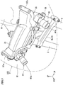
- the support stay 35 is formed in substantially a Y shape in a front view.
- the support stay 35 is integrally formed by, for example, resin molding or aluminum die casting.
- the support stay 35 may have a constitution in which divided bodies are integrally coupled.
- the support stay 35 includes a central leg portion 36 of which a lower end portion is fastened and fixed to the head pipe 6, and left and right arm portions 37 which branch and extend to the left and right from an upper end of the central leg portion 36.
- Mirror fastening portions 37a to which the mirror stays 29b of the left and right rearview mirrors 29 are fastened and fixed are provided at tip ends of the left and right arm portions 37 (left and right ends of the support stay 35).
- the headlight 25 and a meter unit 31 are supported by the support stay 35.
- the meter unit 31 is disposed inside the upper cowl portion 21 so that a display surface thereof faces rearward (toward the passenger side).
- the support stay 35 has strong rigidity as a frame which supports a plurality of accessories at a front portion of the vehicle.
- the motorcycle 1 includes a driving support system 40 using an optical sensor.
- the driving support system 40 includes a pair of left and right cameras (optical sensors) 41 provided on the upper cowl portion 21.
- the left and right cameras 41 constitute a stereo camera which images an object or the like in front of the vehicle from different viewpoints.
- the driving support system 40 allows the left and right cameras 41 to visually recognize (photograph) the front of the vehicle and to detect an object or the like in front of the vehicle.
- the left and right cameras 41 output photographed images to an image processing portion in a control device (not shown) of the driving support system 40.
- the image processing portion performs recognition of the object or like including other vehicles in front of the motorcycle 1 and calculation of a distance between the object and the motorcycle 1, and so on based on the images captured by the left and right cameras 41.
- the left and right cameras 41 can detect the object RB (including a flat object such as paint) on the road surface R.
- the vehicle body such as the front wheel 2 and the front fender 2a may enter an angle of view (radiation/incidence angle in the case of an antenna).
- the left and right cameras 41 can secure a large distance L between the motorcycle 1 (the left and right cameras 41) and the road surface R (the object RB).
- a reference symbol Y in the drawing indicates a height (a vertical distance) from the road surface R to a center (optical axis center) of an outer surface of a lens 41a of each of the left and right cameras 41, and a reference symbol X in the drawing indicates a horizontal distance from the center of the outer surface of the lens 41a to the object RB.
- the image processing portion outputs processing information to a command portion of the control device.
- the command portion outputs commands to carry out driving support such as brake control and steering control for preventing collision of the motorcycle 1 and various warnings to a passenger to each part of the vehicle.
- the driving support system 40 may be associated with a navigation system and a cruise control system.
- the left and right cameras 41 may be used for a drive recorder.
- the headlight 25 includes a lens 25a forming a lamp body, and a housing (not shown).
- a front surface (an outer surface or a light emitting surface) of the lens 25a is disposed on an outer surface of the upper cowl portion 21.
- the housing is disposed inside the upper cowl portion 21.
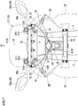
- the left and right cameras 41 are disposed adjacent to each other on the left and right sides of the housing of the headlight 25 inside the upper cowl portion 21.
- the left and right cameras 41 are disposed so that lenses 41a thereof face the front of the vehicle.
- the lenses 41a of the left and right cameras 41 are disposed above left and right ends of the lens 25a of the headlight 25 in a front view.
- a reference symbol P in the drawing indicates a distance between centers of outer surfaces of the lenses 41a of the left and right cameras 41.
- Left and right opening forming portions 32 provided in the upper cowl portion 21 are disposed above the left and right ends of the lens 25a of the headlight 25.
- the left and right opening forming portions 32 are formed in left and right side portions of the upper center cowl 26 or in the left and right upper side cowls 28.
- the left and right opening forming portions 32 expose the lenses 41a of the left and right cameras 41 in the upper cowl portion 21 toward the front of the vehicle through each opening.
- the left and right cameras 41 are capable of photographing the front of the vehicle through the openings of the left and right opening forming portions 32.
- Each of the left and right opening forming portions 32 is covered by a transparent opening cover 33 from the front of the vehicle.
- Left and right opening covers 33 protect the left and right cameras 41 from objects flying in front of the vehicle while allowing the left and right cameras 41 to photograph the front of the vehicle.
- the left and right opening covers 33 are integrally formed at a lower portion of a wind screen 27.
- the meter unit 31 having various instruments and an information display portion is disposed in the rear of the left and right cameras 41 (on the passenger side) inside the upper cowl portion 21.
- the left and right cameras 41 are disposed in a space K1 surrounded by the meter unit 31 and the upper cowl portion 21.
- the left and right cameras 41 are supported by a mount rail 38 extending between the left and right arm portions 37 of the support stay 35.
- the left and right cameras 41 are disposed symmetrically with respect to the lateral center CL of the vehicle.
- the mount rail 38 is provided to extend over an entire lateral width of the support stay 35.
- the mount rail 38 linearly extends in the left and right direction.
- a mount screw shaft 41b extending vertically in the left and right cameras 41 is fastened to the mount rail 38.
- Each of the left and right cameras 41 is fixed to the mount rail 38 via the mount screw shaft 41b.
- the left and right cameras 41 are rigidly mounted (rigidly fixed without using an elastic member) to the mount rail 38.
- the mount rail 38 is integrally coupled to the support stay 35.
- the mount rail 38 may be integrated with the support stay 35.
- the mount rail 38 may be formed of a pipe material extending in the left and right directions, and the left and right cameras 41 may be fixed to the mount rail 38 by a clamping unit (not shown) or the like.
- Fixing positions of the left and right cameras 41 with respect to the mount rail 38 in the left and right directions may be capable of being adjusted.
- Fixing angles of the left and right cameras 41 with respect to the respective mount screw shafts 41b in a plan view may be capable of being adjusted.
- a mechanism which allows the fixing angle of the left and right cameras 41 in a side view to be adjusted may be provided between the left and right cameras 41 and the mount rail 38.
- the left and right cameras 41 are disposed to be located on the left and right outer sides from the left and right front forks 3 as a whole. Each of the left and right cameras 41 may be disposed such that at least a part thereof is located on the outer side in the left and right directions from the left and right front forks 3.
- the left and right cameras 41 serve as the stereo camera and improve calculation accuracy of depth information (distance information in forward and rearward directions) of the object at a long distance by widening the distance P between them.
- the fixing position and angle of the left and right cameras 41 can be adjusted with respect to the mount rail 38 which generally extends over an entire lateral width of the support stay 35 (additionally, an entire lateral width of the upper cowl portion 21). Therefore, even in a compact vehicle such as a saddled vehicle, as great a distance P between the left and right cameras 41 as possible can be ensured.
- the accuracy of calculating the distance information of the object can be improved by securing the distance P between the left and right cameras 41.
- the left and right cameras 41 are disposed to be located above the bottom bridge 4b as a whole. Each of the left and right cameras 41 is disposed so that at least a part thereof is located above the top bridge 4a. The left and right cameras 41 may be disposed to be located above the top bridge 4a as a whole.
- the left and right cameras 41 When the position of the left and right cameras 41 is low (close to the road surface R), a proportion occupied by the road surface R in a detection range increases. On the other hand, when the position of the left and right cameras 41 is high, a proportion occupied by a space above the road surface in the detection range increases.
- the left and right cameras 41 are disposed at as high a position as possible inside the upper cowl portion 21, and detection accuracy of the object in front of the vehicle is enhanced. When the position of the left and right cameras 41 is high, a large distance L between the left and right cameras 41 and the road surface R can be secured, and detection of road surface conditions can be performed with higher accuracy.
- the optical sensor supporting structure for saddled vehicles includes the left and right cameras 41 which are configured to detect the object in front of the vehicle, and the support stay 35 which is fixed to the head pipe 6 of the vehicle body frame 5 to support the accessories at the front of the vehicle on the head pipe 6, and the left and right cameras 41 are supported by the support stay 35.
- the left and right cameras 41 are supported by the support stay 35 having high rigidity, it is possible to minimize shifting of the relative position of the left and right cameras 41, as compared with a constitution in which the left and right cameras 41 are disposed on the rearview mirrors 29 or the like. Therefore, it is possible to accurately detect the distance between the object in front of the vehicle and the vehicle. In addition, it is possible to ensure usability of the accessories without affecting movement of the accessories such as the rearview mirrors 29.
- Vibration applied to the left and right cameras 41 is reduced by the support stay 35 having the high rigidity, and it is possible to maintain the satisfactory detection accuracy in front of the vehicle while minimizing a cost increase without using a high-function (high-priced) camera.
- the relative position and angle of the left and right cameras 41 do not easily shift, and the distance to the object in front of the vehicle and so on can be measured with high accuracy.
- the optical sensor supporting structure for saddled vehicles in the first embodiment includes the left and right front forks 3 which pivotally support the front wheel 2, and the left and right cameras 41 are disposed on the outer side of the left and right front forks 3 in a width direction of the vehicle in a front view.
- the optical sensor supporting structure for saddled vehicles in the first embodiment includes the bottom bridge 4b which connects a space between the left and right front forks 3, and the left and right cameras 41 are disposed above the bottom bridge 4b.
- the bottom bridge 4b can minimize external disturbance from the lower side to the left and right cameras 41. Further, the proportion occupied by the space above the road surface in the detection range of the left and right cameras 41 is increased by setting the position of the left and right cameras 41 to be high, and thus the detection accuracy in front of the vehicle can be enhanced. Also, when the position of the left and right cameras 41 is high, a large distance L between the left and right cameras 41 and the road surface R can be secured without changing the angle of view, and the detection of the road surface conditions can be performed with higher accuracy.
- the support stay 35 includes the mount rail 38 which fixes the left and right cameras 41 with the width direction of the vehicle being a lengthwise direction.
- a degree of freedom of arrangement of the left and right cameras 41 in the width direction of the vehicle can be increased. Further, since the left and right cameras 41 are supported by the mount rail 38 extending in the width direction of the vehicle, it is easy to set the fixing position and angle of the left and right cameras 41 symmetrically, and thus the left and right cameras 41 can be easily mounted.
- the support stay 35 serves to support the rearview mirrors 29, and the mount rail 38 for the left and right cameras 41 can be provided in an elongated manner to extend over the entire lateral width of the support stay 35. Due to the long mount rail 38, the distance P between the left and right cameras 41 can be easily secured.
- the left and right cameras 41 are rigidly mounted on the support stay 35.
- the optical sensor supporting structure for saddled vehicles in the first embodiment includes the meter unit 31 which is supported by the support stay 35, and the upper cowl portion 21 which covers the front of the meter unit 31, and the left and right cameras 41 are disposed in the space K1 surrounded by the meter unit 31 and the upper cowl portion 21.
- the left and right cameras 41 can be disposed to be inconspicuous from the outer side of the vehicle and the passenger side.
- the second embodiment is different from the first embodiment in the arrangement of the mount rail and the left and right cameras.
- the same components as those of the first embodiment are designated by the same reference numerals, and a detailed description thereof will be omitted.
- a mount rail 138 and the left and right cameras 41 are disposed outside the upper cowl portion 21.
- the mount rail 138 is provided across the mounting seat for the left and right rearview mirrors 29 in the upper cowl portion 21.
- the mount rail 138 is fastened and fixed to left and right mirror fastening portions 37a of the support stay 35 together with base ends of left and right mirror stays 29b.
- the mount rail 138 extends linearly in the left and right direction.
- the mount rail 138 is formed of, for example, a tubular material having a flat four-sided cross section.
- the mount rail 138 is formed of, for example, a rectangular steel pipe.
- the mount rail 138 may be formed of other cross-sectional shapes or materials.
- the left and right cameras 41 are fixed (rigidly mounted) to the mount rail 138 by a clamping unit (not shown) or the like.
- the left and right cameras 41 may be fixed to the mount rail 138 via a screw shaft, like in the first embodiment.
- the left and right mirror fastening portions 37a are located on the left and right outermost sides of the support stay 35. A length of the mount rail 138 can be easily ensured by fixing the mount rail 138 over the left and right mirror fastening portions 37a, and the distance P between the left and right cameras 41 can be easily secured.
- the left and right cameras 41 are supported by the support stay 35 having the high rigidity, it is possible to minimize the shifting of the relative position of the left and right cameras 41, as compared with a constitution in which the left and right cameras 41 are disposed on the rearview mirrors 29 or the like. Therefore, it is possible to accurately detect the distance between the object in front of the vehicle and the vehicle. In addition, it is possible to ensure usability of the accessories without affecting the movement of the accessories such as the rearview mirrors 29.
- Vibration applied to the left and right cameras 41 is reduced by the support stay 35 having the high rigidity, and it is possible to maintain the satisfactory detection accuracy in front of the vehicle while minimizing the cost increase without using a high-function (high-priced) camera.
- the relative position and angle of the left and right cameras 41 are ulikely to shift, and the distance to the object in front of the vehicle and so on can be measured with high accuracy.
- the left and right cameras 41 are disposed on the outer side of the left and right front forks 3 in the width direction of the vehicle in a front view. Therefore, it is possible to sufficiently ensure the distance P between the left and right cameras 41 in the width direction of the vehicle with the left and right front forks 3 interposed therebetween and to accurately measure the distance between the object in front of the vehicle and the vehicle.
- the left and right cameras 41 are disposed above the bottom bridge 4b. Therefore, the bottom bridge 4b can minimize the external disturbance from the lower side to the left and right cameras 41. Further, the proportion occupied by the space above the road surface in the detection range of the left and right cameras 41 is increased by setting the position of the left and right cameras 41 to be high, and thus the detection accuracy in front of the vehicle can be enhanced. Also, when the position of the left and right cameras 41 is high, the distance L between the left and right cameras 41 and the road surface R can be secured large without changing the angle of view, and the detection of the road surface conditions can be performed with higher accuracy.
- the mount rail 138 fixes the left and right cameras 41 with the width direction of the vehicle being a lengthwise direction. Therefore, a degree of freedom of arrangement of the left and right cameras 41 in the width direction of the vehicle can be increased. Further, since the left and right cameras 41 are supported by the mount rail 138 extending in the width direction of the vehicle, it is easy to set the fixing position and angle of the left and right cameras 41 symmetrically, and thus the left and right cameras 41 can be easily mounted.
- the support stay 35 serves to support the rearview mirrors 29, and the mount rail 138 for the left and right cameras 41 can be provided in an elongated manner to extend over the entire lateral width of the support stay 35. Due to the long mount rail 138, the distance P between the left and right cameras 41 can be easily secured.
- the left and right cameras 41 are rigidly mounted on the support stay 35. Therefore, it is easy to hold the left and right cameras 41 in parallel at a prescribed fixing position and angle and to accurately measure the distance to the object in front of the vehicle and so on, as compared with the case in which the left and right cameras 41 are rubber-mounted.
- the support stay 35 is disposed at a position which is easily accessible from the outer side, it is easy to divert the mount rail 138 to other vehicles. Therefore, versatility of the mount rail 138 is improved, and a structure with reduced cost can be obtained.
- the camera may be a camera which images invisible light such as infrared rays as well as visible light. It may be not only a camera but also an optical sensor such as a radar using infrared rays or millimeter waves or the like. A constitution using a single optical sensor instead of the pair of left and right optical sensors may be used.
- the camera and the radar may be used together.
- the arrangement of the lens of the camera in the above embodiments is an arrangement of an antenna.
- the support stay may be fixed to another part (main tube or the like) of the vehicle body frame, in addition to the head pipe of the vehicle body frame.
- the saddled vehicles include any vehicle in which a driver straddles a vehicle body when riding it and include not only motorcycles (including bicycles with prime movers and a scooter type vehicles), but also three-wheeled (including two-front-wheel and one-rear-wheel vehicles in addition to one-front-wheel and two-rear-wheel vehicles) or four-wheeled vehicles.
Landscapes
- Engineering & Computer Science (AREA)
- Mechanical Engineering (AREA)
- Physics & Mathematics (AREA)
- General Physics & Mathematics (AREA)
- Multimedia (AREA)
- Length Measuring Devices By Optical Means (AREA)
- Fittings On The Vehicle Exterior For Carrying Loads, And Devices For Holding Or Mounting Articles (AREA)
- Motorcycle And Bicycle Frame (AREA)
Applications Claiming Priority (1)
| Application Number | Priority Date | Filing Date | Title |
|---|---|---|---|
| PCT/JP2016/068839 WO2017221410A1 (fr) | 2016-06-24 | 2016-06-24 | Structure de support de capteur optique destinée à des véhicules à selle |
Publications (3)
| Publication Number | Publication Date |
|---|---|
| EP3476708A1 true EP3476708A1 (fr) | 2019-05-01 |
| EP3476708A4 EP3476708A4 (fr) | 2019-06-05 |
| EP3476708B1 EP3476708B1 (fr) | 2022-02-23 |
Family
ID=60783914
Family Applications (1)
| Application Number | Title | Priority Date | Filing Date |
|---|---|---|---|
| EP16906327.8A Active EP3476708B1 (fr) | 2016-06-24 | 2016-06-24 | Structure de support de capteur optique destinée à des véhicules à selle |
Country Status (4)
| Country | Link |
|---|---|
| US (1) | US10562477B2 (fr) |
| EP (1) | EP3476708B1 (fr) |
| JP (1) | JP6684903B2 (fr) |
| WO (1) | WO2017221410A1 (fr) |
Cited By (3)
| Publication number | Priority date | Publication date | Assignee | Title |
|---|---|---|---|---|
| EP3838728A1 (fr) * | 2019-12-19 | 2021-06-23 | Kawasaki Jukogyo Kabushiki Kaisha | Véhicule à enfourcher |
| EP3838726A1 (fr) * | 2019-12-19 | 2021-06-23 | Kawasaki Jukogyo Kabushiki Kaisha | Véhicule à enfourcher |
| DE102019135443B4 (de) | 2018-12-21 | 2024-10-31 | Kawasaki Motors, Ltd. | Fahrzeug vom sattelfahrtyp |
Families Citing this family (14)
| Publication number | Priority date | Publication date | Assignee | Title |
|---|---|---|---|---|
| WO2018101374A1 (fr) * | 2016-12-01 | 2018-06-07 | ヤマハ発動機株式会社 | Véhicule inclinable |
| WO2019180941A1 (fr) | 2018-03-23 | 2019-09-26 | 本田技研工業株式会社 | Véhicule de type à selle |
| DE112018007332B4 (de) | 2018-03-23 | 2023-03-02 | Honda Motor Co., Ltd. | Grätschsitzfahrzeug |
| DE112018007390B4 (de) * | 2018-03-29 | 2023-08-24 | Honda Motor Co., Ltd. | Grätschsitzfahrzeug |
| JP7078710B2 (ja) * | 2018-03-29 | 2022-05-31 | 本田技研工業株式会社 | 鞍乗型車両 |
| JP7084476B2 (ja) | 2018-05-23 | 2022-06-14 | 本田技研工業株式会社 | 鞍乗型車両 |
| JP7198602B2 (ja) | 2018-07-11 | 2023-01-04 | カワサキモータース株式会社 | 自動二輪車 |
| CN111422287B (zh) * | 2018-12-21 | 2022-02-08 | 本田技研工业株式会社 | 跨骑型车辆 |
| JP6859380B2 (ja) * | 2019-03-12 | 2021-04-14 | 本田技研工業株式会社 | 鞍乗型車両の電装品取付構造 |
| WO2022239324A1 (fr) * | 2021-05-13 | 2022-11-17 | 日立Astemo株式会社 | Dispositif de montage et procédé de montage |
| IT202100017471A1 (it) * | 2021-07-02 | 2023-01-02 | Piaggio & C Spa | Veicolo a sella cavalcabile dotato di unità di rilevamento |
| JP2024102608A (ja) * | 2023-01-19 | 2024-07-31 | ヤマハ発動機株式会社 | 鞍乗型車両 |
| US12606262B2 (en) * | 2023-03-08 | 2026-04-21 | Kawasaki Motors, Ltd. | Straddle vehicle and detecting structure |
| WO2025079324A1 (fr) * | 2023-10-12 | 2025-04-17 | 日立Astemo株式会社 | Structure d'agencement de caméra pour véhicule à selle |
Family Cites Families (6)
| Publication number | Priority date | Publication date | Assignee | Title |
|---|---|---|---|---|
| JP2001158390A (ja) * | 1999-11-30 | 2001-06-12 | Yamaha Motor Co Ltd | 鞍乗型車両用車両間通信装置 |
| JP2007112368A (ja) * | 2005-10-24 | 2007-05-10 | Tgal:Kk | 車両用後側方確認カメラ装置 |
| JP2009023543A (ja) * | 2007-07-20 | 2009-02-05 | Kawasaki Heavy Ind Ltd | 乗物、および乗物の運転支援装置 |
| EP2757030B1 (fr) * | 2008-01-24 | 2015-12-23 | Cycling Sports Group, Inc. | Système d'interface utilisateur de bicyclette et son procédé de fonctionnement |
| JP6543823B2 (ja) * | 2016-05-13 | 2019-07-17 | 本田技研工業株式会社 | 鞍乗り型車両の光学センサ配置構造 |
| JP6628411B2 (ja) * | 2016-05-13 | 2020-01-08 | 本田技研工業株式会社 | 鞍乗り型車両の光学センサ配置構造 |
-
2016
- 2016-06-24 US US16/300,981 patent/US10562477B2/en active Active
- 2016-06-24 EP EP16906327.8A patent/EP3476708B1/fr active Active
- 2016-06-24 JP JP2018523259A patent/JP6684903B2/ja active Active
- 2016-06-24 WO PCT/JP2016/068839 patent/WO2017221410A1/fr not_active Ceased
Cited By (5)
| Publication number | Priority date | Publication date | Assignee | Title |
|---|---|---|---|---|
| DE102019135443B4 (de) | 2018-12-21 | 2024-10-31 | Kawasaki Motors, Ltd. | Fahrzeug vom sattelfahrtyp |
| EP3838728A1 (fr) * | 2019-12-19 | 2021-06-23 | Kawasaki Jukogyo Kabushiki Kaisha | Véhicule à enfourcher |
| EP3838726A1 (fr) * | 2019-12-19 | 2021-06-23 | Kawasaki Jukogyo Kabushiki Kaisha | Véhicule à enfourcher |
| US11753103B2 (en) | 2019-12-19 | 2023-09-12 | Kawasaki Motors, Ltd. | Straddle vehicle |
| US11939021B2 (en) | 2019-12-19 | 2024-03-26 | Kawasaki Motors, Ltd. | Straddle vehicle having a camera |
Also Published As
| Publication number | Publication date |
|---|---|
| WO2017221410A1 (fr) | 2017-12-28 |
| EP3476708A4 (fr) | 2019-06-05 |
| US20190161042A1 (en) | 2019-05-30 |
| JPWO2017221410A1 (ja) | 2019-01-31 |
| EP3476708B1 (fr) | 2022-02-23 |
| JP6684903B2 (ja) | 2020-04-22 |
| US10562477B2 (en) | 2020-02-18 |
Similar Documents
| Publication | Publication Date | Title |
|---|---|---|
| EP3476708B1 (fr) | Structure de support de capteur optique destinée à des véhicules à selle | |
| JP6628411B2 (ja) | 鞍乗り型車両の光学センサ配置構造 | |
| JP6543823B2 (ja) | 鞍乗り型車両の光学センサ配置構造 | |
| JP5628778B2 (ja) | 車載カメラの取り付け装置 | |
| US11214325B2 (en) | Straddle type vehicle | |
| JP2009023543A (ja) | 乗物、および乗物の運転支援装置 | |
| JP7063986B2 (ja) | 鞍乗型車両 | |
| US9039258B2 (en) | Headlight support structure for saddle type vehicle | |
| US9256952B2 (en) | Vehicle speed calculator, and vehicle including same | |
| JP4771403B2 (ja) | Gps内蔵メータ | |
| CN109641630B (zh) | 跨骑型车辆 | |
| US10408405B2 (en) | Lighting apparatus arrangement for saddle riding vehicle, and saddle riding vehicle | |
| JP6839119B2 (ja) | 鞍乗り型車両 | |
| EP3508406B1 (fr) | Véhicule de type à selle | |
| JP6873070B2 (ja) | 鞍乗り型車両の灯火装置配置構造 | |
| JP5851009B2 (ja) | 車載カメラの取り付け装置 | |
| US9699421B2 (en) | Motorcycle having a video camera mounted thereon for monitoring a road surface, and methods of using same | |
| US12024255B2 (en) | Straddle type vehicle | |
| US10379343B2 (en) | Saddle riding vehicle | |
| JP3230387U (ja) | 鞍乗り型車両の前部構造 | |
| JP2019001301A (ja) | 自動二輪車 | |
| WO2025100011A1 (fr) | Structure d'agencement de caméra pour véhicule à selle |
Legal Events
| Date | Code | Title | Description |
|---|---|---|---|
| STAA | Information on the status of an ep patent application or granted ep patent |
Free format text: STATUS: THE INTERNATIONAL PUBLICATION HAS BEEN MADE |
|
| PUAI | Public reference made under article 153(3) epc to a published international application that has entered the european phase |
Free format text: ORIGINAL CODE: 0009012 |
|
| STAA | Information on the status of an ep patent application or granted ep patent |
Free format text: STATUS: REQUEST FOR EXAMINATION WAS MADE |
|
| 17P | Request for examination filed |
Effective date: 20181119 |
|
| AK | Designated contracting states |
Kind code of ref document: A1 Designated state(s): AL AT BE BG CH CY CZ DE DK EE ES FI FR GB GR HR HU IE IS IT LI LT LU LV MC MK MT NL NO PL PT RO RS SE SI SK SM TR |
|
| AX | Request for extension of the european patent |
Extension state: BA ME |
|
| A4 | Supplementary search report drawn up and despatched |
Effective date: 20190507 |
|
| RIC1 | Information provided on ipc code assigned before grant |
Ipc: B62J 99/00 20090101AFI20190430BHEP Ipc: B62K 19/40 20060101ALI20190430BHEP Ipc: B60R 11/02 20060101ALI20190430BHEP Ipc: B62K 11/04 20060101ALI20190430BHEP |
|
| DAV | Request for validation of the european patent (deleted) | ||
| DAX | Request for extension of the european patent (deleted) | ||
| STAA | Information on the status of an ep patent application or granted ep patent |
Free format text: STATUS: EXAMINATION IS IN PROGRESS |
|
| 17Q | First examination report despatched |
Effective date: 20191216 |
|
| GRAP | Despatch of communication of intention to grant a patent |
Free format text: ORIGINAL CODE: EPIDOSNIGR1 |
|
| STAA | Information on the status of an ep patent application or granted ep patent |
Free format text: STATUS: GRANT OF PATENT IS INTENDED |
|
| INTG | Intention to grant announced |
Effective date: 20210921 |
|
| GRAS | Grant fee paid |
Free format text: ORIGINAL CODE: EPIDOSNIGR3 |
|
| GRAA | (expected) grant |
Free format text: ORIGINAL CODE: 0009210 |
|
| STAA | Information on the status of an ep patent application or granted ep patent |
Free format text: STATUS: THE PATENT HAS BEEN GRANTED |
|
| AK | Designated contracting states |
Kind code of ref document: B1 Designated state(s): AL AT BE BG CH CY CZ DE DK EE ES FI FR GB GR HR HU IE IS IT LI LT LU LV MC MK MT NL NO PL PT RO RS SE SI SK SM TR |
|
| REG | Reference to a national code |
Ref country code: GB Ref legal event code: FG4D |
|
| REG | Reference to a national code |
Ref country code: CH Ref legal event code: EP |
|
| REG | Reference to a national code |
Ref country code: AT Ref legal event code: REF Ref document number: 1470264 Country of ref document: AT Kind code of ref document: T Effective date: 20220315 |
|
| REG | Reference to a national code |
Ref country code: IE Ref legal event code: FG4D |
|
| REG | Reference to a national code |
Ref country code: DE Ref legal event code: R096 Ref document number: 602016069482 Country of ref document: DE |
|
| REG | Reference to a national code |
Ref country code: LT Ref legal event code: MG9D |
|
| REG | Reference to a national code |
Ref country code: NL Ref legal event code: MP Effective date: 20220223 |
|
| REG | Reference to a national code |
Ref country code: AT Ref legal event code: MK05 Ref document number: 1470264 Country of ref document: AT Kind code of ref document: T Effective date: 20220223 |
|
| PG25 | Lapsed in a contracting state [announced via postgrant information from national office to epo] |
Ref country code: SE Free format text: LAPSE BECAUSE OF FAILURE TO SUBMIT A TRANSLATION OF THE DESCRIPTION OR TO PAY THE FEE WITHIN THE PRESCRIBED TIME-LIMIT Effective date: 20220223 Ref country code: RS Free format text: LAPSE BECAUSE OF FAILURE TO SUBMIT A TRANSLATION OF THE DESCRIPTION OR TO PAY THE FEE WITHIN THE PRESCRIBED TIME-LIMIT Effective date: 20220223 Ref country code: PT Free format text: LAPSE BECAUSE OF FAILURE TO SUBMIT A TRANSLATION OF THE DESCRIPTION OR TO PAY THE FEE WITHIN THE PRESCRIBED TIME-LIMIT Effective date: 20220623 Ref country code: NO Free format text: LAPSE BECAUSE OF FAILURE TO SUBMIT A TRANSLATION OF THE DESCRIPTION OR TO PAY THE FEE WITHIN THE PRESCRIBED TIME-LIMIT Effective date: 20220523 Ref country code: NL Free format text: LAPSE BECAUSE OF FAILURE TO SUBMIT A TRANSLATION OF THE DESCRIPTION OR TO PAY THE FEE WITHIN THE PRESCRIBED TIME-LIMIT Effective date: 20220223 Ref country code: LT Free format text: LAPSE BECAUSE OF FAILURE TO SUBMIT A TRANSLATION OF THE DESCRIPTION OR TO PAY THE FEE WITHIN THE PRESCRIBED TIME-LIMIT Effective date: 20220223 Ref country code: HR Free format text: LAPSE BECAUSE OF FAILURE TO SUBMIT A TRANSLATION OF THE DESCRIPTION OR TO PAY THE FEE WITHIN THE PRESCRIBED TIME-LIMIT Effective date: 20220223 Ref country code: ES Free format text: LAPSE BECAUSE OF FAILURE TO SUBMIT A TRANSLATION OF THE DESCRIPTION OR TO PAY THE FEE WITHIN THE PRESCRIBED TIME-LIMIT Effective date: 20220223 Ref country code: BG Free format text: LAPSE BECAUSE OF FAILURE TO SUBMIT A TRANSLATION OF THE DESCRIPTION OR TO PAY THE FEE WITHIN THE PRESCRIBED TIME-LIMIT Effective date: 20220523 |
|
| REG | Reference to a national code |
Ref country code: DE Ref legal event code: R084 Ref document number: 602016069482 Country of ref document: DE |
|
| PG25 | Lapsed in a contracting state [announced via postgrant information from national office to epo] |
Ref country code: PL Free format text: LAPSE BECAUSE OF FAILURE TO SUBMIT A TRANSLATION OF THE DESCRIPTION OR TO PAY THE FEE WITHIN THE PRESCRIBED TIME-LIMIT Effective date: 20220223 Ref country code: LV Free format text: LAPSE BECAUSE OF FAILURE TO SUBMIT A TRANSLATION OF THE DESCRIPTION OR TO PAY THE FEE WITHIN THE PRESCRIBED TIME-LIMIT Effective date: 20220223 Ref country code: GR Free format text: LAPSE BECAUSE OF FAILURE TO SUBMIT A TRANSLATION OF THE DESCRIPTION OR TO PAY THE FEE WITHIN THE PRESCRIBED TIME-LIMIT Effective date: 20220524 Ref country code: FI Free format text: LAPSE BECAUSE OF FAILURE TO SUBMIT A TRANSLATION OF THE DESCRIPTION OR TO PAY THE FEE WITHIN THE PRESCRIBED TIME-LIMIT Effective date: 20220223 Ref country code: AT Free format text: LAPSE BECAUSE OF FAILURE TO SUBMIT A TRANSLATION OF THE DESCRIPTION OR TO PAY THE FEE WITHIN THE PRESCRIBED TIME-LIMIT Effective date: 20220223 |
|
| PG25 | Lapsed in a contracting state [announced via postgrant information from national office to epo] |
Ref country code: IS Free format text: LAPSE BECAUSE OF FAILURE TO SUBMIT A TRANSLATION OF THE DESCRIPTION OR TO PAY THE FEE WITHIN THE PRESCRIBED TIME-LIMIT Effective date: 20220623 |
|
| PG25 | Lapsed in a contracting state [announced via postgrant information from national office to epo] |
Ref country code: SM Free format text: LAPSE BECAUSE OF FAILURE TO SUBMIT A TRANSLATION OF THE DESCRIPTION OR TO PAY THE FEE WITHIN THE PRESCRIBED TIME-LIMIT Effective date: 20220223 Ref country code: SK Free format text: LAPSE BECAUSE OF FAILURE TO SUBMIT A TRANSLATION OF THE DESCRIPTION OR TO PAY THE FEE WITHIN THE PRESCRIBED TIME-LIMIT Effective date: 20220223 Ref country code: RO Free format text: LAPSE BECAUSE OF FAILURE TO SUBMIT A TRANSLATION OF THE DESCRIPTION OR TO PAY THE FEE WITHIN THE PRESCRIBED TIME-LIMIT Effective date: 20220223 Ref country code: EE Free format text: LAPSE BECAUSE OF FAILURE TO SUBMIT A TRANSLATION OF THE DESCRIPTION OR TO PAY THE FEE WITHIN THE PRESCRIBED TIME-LIMIT Effective date: 20220223 Ref country code: DK Free format text: LAPSE BECAUSE OF FAILURE TO SUBMIT A TRANSLATION OF THE DESCRIPTION OR TO PAY THE FEE WITHIN THE PRESCRIBED TIME-LIMIT Effective date: 20220223 Ref country code: CZ Free format text: LAPSE BECAUSE OF FAILURE TO SUBMIT A TRANSLATION OF THE DESCRIPTION OR TO PAY THE FEE WITHIN THE PRESCRIBED TIME-LIMIT Effective date: 20220223 |
|
| REG | Reference to a national code |
Ref country code: DE Ref legal event code: R097 Ref document number: 602016069482 Country of ref document: DE |
|
| PG25 | Lapsed in a contracting state [announced via postgrant information from national office to epo] |
Ref country code: AL Free format text: LAPSE BECAUSE OF FAILURE TO SUBMIT A TRANSLATION OF THE DESCRIPTION OR TO PAY THE FEE WITHIN THE PRESCRIBED TIME-LIMIT Effective date: 20220223 |
|
| PLBE | No opposition filed within time limit |
Free format text: ORIGINAL CODE: 0009261 |
|
| STAA | Information on the status of an ep patent application or granted ep patent |
Free format text: STATUS: NO OPPOSITION FILED WITHIN TIME LIMIT |
|
| PG25 | Lapsed in a contracting state [announced via postgrant information from national office to epo] |
Ref country code: MC Free format text: LAPSE BECAUSE OF FAILURE TO SUBMIT A TRANSLATION OF THE DESCRIPTION OR TO PAY THE FEE WITHIN THE PRESCRIBED TIME-LIMIT Effective date: 20220223 |
|
| REG | Reference to a national code |
Ref country code: CH Ref legal event code: PL |
|
| 26N | No opposition filed |
Effective date: 20221124 |
|
| REG | Reference to a national code |
Ref country code: BE Ref legal event code: MM Effective date: 20220630 |
|
| PG25 | Lapsed in a contracting state [announced via postgrant information from national office to epo] |
Ref country code: SI Free format text: LAPSE BECAUSE OF FAILURE TO SUBMIT A TRANSLATION OF THE DESCRIPTION OR TO PAY THE FEE WITHIN THE PRESCRIBED TIME-LIMIT Effective date: 20220223 |
|
| GBPC | Gb: european patent ceased through non-payment of renewal fee |
Effective date: 20220624 |
|
| PG25 | Lapsed in a contracting state [announced via postgrant information from national office to epo] |
Ref country code: LU Free format text: LAPSE BECAUSE OF NON-PAYMENT OF DUE FEES Effective date: 20220624 Ref country code: LI Free format text: LAPSE BECAUSE OF NON-PAYMENT OF DUE FEES Effective date: 20220630 Ref country code: IE Free format text: LAPSE BECAUSE OF NON-PAYMENT OF DUE FEES Effective date: 20220624 Ref country code: FR Free format text: LAPSE BECAUSE OF NON-PAYMENT OF DUE FEES Effective date: 20220630 Ref country code: CH Free format text: LAPSE BECAUSE OF NON-PAYMENT OF DUE FEES Effective date: 20220630 |
|
| PG25 | Lapsed in a contracting state [announced via postgrant information from national office to epo] |
Ref country code: GB Free format text: LAPSE BECAUSE OF NON-PAYMENT OF DUE FEES Effective date: 20220624 Ref country code: BE Free format text: LAPSE BECAUSE OF NON-PAYMENT OF DUE FEES Effective date: 20220630 |
|
| PG25 | Lapsed in a contracting state [announced via postgrant information from national office to epo] |
Ref country code: IT Free format text: LAPSE BECAUSE OF FAILURE TO SUBMIT A TRANSLATION OF THE DESCRIPTION OR TO PAY THE FEE WITHIN THE PRESCRIBED TIME-LIMIT Effective date: 20220223 |
|
| PG25 | Lapsed in a contracting state [announced via postgrant information from national office to epo] |
Ref country code: HU Free format text: LAPSE BECAUSE OF FAILURE TO SUBMIT A TRANSLATION OF THE DESCRIPTION OR TO PAY THE FEE WITHIN THE PRESCRIBED TIME-LIMIT; INVALID AB INITIO Effective date: 20160624 |
|
| PG25 | Lapsed in a contracting state [announced via postgrant information from national office to epo] |
Ref country code: MK Free format text: LAPSE BECAUSE OF FAILURE TO SUBMIT A TRANSLATION OF THE DESCRIPTION OR TO PAY THE FEE WITHIN THE PRESCRIBED TIME-LIMIT Effective date: 20220223 Ref country code: CY Free format text: LAPSE BECAUSE OF FAILURE TO SUBMIT A TRANSLATION OF THE DESCRIPTION OR TO PAY THE FEE WITHIN THE PRESCRIBED TIME-LIMIT Effective date: 20220223 |
|
| PG25 | Lapsed in a contracting state [announced via postgrant information from national office to epo] |
Ref country code: TR Free format text: LAPSE BECAUSE OF FAILURE TO SUBMIT A TRANSLATION OF THE DESCRIPTION OR TO PAY THE FEE WITHIN THE PRESCRIBED TIME-LIMIT Effective date: 20220223 |
|
| PG25 | Lapsed in a contracting state [announced via postgrant information from national office to epo] |
Ref country code: MT Free format text: LAPSE BECAUSE OF FAILURE TO SUBMIT A TRANSLATION OF THE DESCRIPTION OR TO PAY THE FEE WITHIN THE PRESCRIBED TIME-LIMIT Effective date: 20220223 |
|
| PGFP | Annual fee paid to national office [announced via postgrant information from national office to epo] |
Ref country code: DE Payment date: 20250520 Year of fee payment: 10 |