EP3477202B1 - Panneaux de chambre de combustion à paroi flotante présentant des caractéristiques de distribution de flux d'air - Google Patents
Panneaux de chambre de combustion à paroi flotante présentant des caractéristiques de distribution de flux d'air Download PDFInfo
- Publication number
- EP3477202B1 EP3477202B1 EP18202988.4A EP18202988A EP3477202B1 EP 3477202 B1 EP3477202 B1 EP 3477202B1 EP 18202988 A EP18202988 A EP 18202988A EP 3477202 B1 EP3477202 B1 EP 3477202B1
- Authority
- EP
- European Patent Office
- Prior art keywords
- combustor
- cooling
- panel
- pin
- pin array
- Prior art date
- Legal status (The legal status is an assumption and is not a legal conclusion. Google has not performed a legal analysis and makes no representation as to the accuracy of the status listed.)
- Active
Links
Images


Classifications
-
- F—MECHANICAL ENGINEERING; LIGHTING; HEATING; WEAPONS; BLASTING
- F02—COMBUSTION ENGINES; HOT-GAS OR COMBUSTION-PRODUCT ENGINE PLANTS
- F02C—GAS-TURBINE PLANTS; AIR INTAKES FOR JET-PROPULSION PLANTS; CONTROLLING FUEL SUPPLY IN AIR-BREATHING JET-PROPULSION PLANTS
- F02C7/00—Features, components parts, details or accessories, not provided for in, or of interest apart form groups F02C1/00 - F02C6/00; Air intakes for jet-propulsion plants
- F02C7/12—Cooling of plants
- F02C7/16—Cooling of plants characterised by cooling medium
- F02C7/18—Cooling of plants characterised by cooling medium the medium being gaseous, e.g. air
-
- F—MECHANICAL ENGINEERING; LIGHTING; HEATING; WEAPONS; BLASTING
- F23—COMBUSTION APPARATUS; COMBUSTION PROCESSES
- F23R—GENERATING COMBUSTION PRODUCTS OF HIGH PRESSURE OR HIGH VELOCITY, e.g. GAS-TURBINE COMBUSTION CHAMBERS
- F23R3/00—Continuous combustion chambers using liquid or gaseous fuel
- F23R3/002—Wall structures
-
- F—MECHANICAL ENGINEERING; LIGHTING; HEATING; WEAPONS; BLASTING
- F23—COMBUSTION APPARATUS; COMBUSTION PROCESSES
- F23R—GENERATING COMBUSTION PRODUCTS OF HIGH PRESSURE OR HIGH VELOCITY, e.g. GAS-TURBINE COMBUSTION CHAMBERS
- F23R3/00—Continuous combustion chambers using liquid or gaseous fuel
- F23R3/02—Continuous combustion chambers using liquid or gaseous fuel characterised by the air-flow or gas-flow configuration
- F23R3/04—Air inlet arrangements
-
- F—MECHANICAL ENGINEERING; LIGHTING; HEATING; WEAPONS; BLASTING
- F05—INDEXING SCHEMES RELATING TO ENGINES OR PUMPS IN VARIOUS SUBCLASSES OF CLASSES F01-F04
- F05D—INDEXING SCHEME FOR ASPECTS RELATING TO NON-POSITIVE-DISPLACEMENT MACHINES OR ENGINES, GAS-TURBINES OR JET-PROPULSION PLANTS
- F05D2220/00—Application
- F05D2220/30—Application in turbines
- F05D2220/32—Application in turbines in gas turbines
-
- F—MECHANICAL ENGINEERING; LIGHTING; HEATING; WEAPONS; BLASTING
- F05—INDEXING SCHEMES RELATING TO ENGINES OR PUMPS IN VARIOUS SUBCLASSES OF CLASSES F01-F04
- F05D—INDEXING SCHEME FOR ASPECTS RELATING TO NON-POSITIVE-DISPLACEMENT MACHINES OR ENGINES, GAS-TURBINES OR JET-PROPULSION PLANTS
- F05D2240/00—Components
- F05D2240/35—Combustors or associated equipment
-
- F—MECHANICAL ENGINEERING; LIGHTING; HEATING; WEAPONS; BLASTING
- F05—INDEXING SCHEMES RELATING TO ENGINES OR PUMPS IN VARIOUS SUBCLASSES OF CLASSES F01-F04
- F05D—INDEXING SCHEME FOR ASPECTS RELATING TO NON-POSITIVE-DISPLACEMENT MACHINES OR ENGINES, GAS-TURBINES OR JET-PROPULSION PLANTS
- F05D2260/00—Function
- F05D2260/20—Heat transfer, e.g. cooling
- F05D2260/221—Improvement of heat transfer
- F05D2260/2214—Improvement of heat transfer by increasing the heat transfer surface
-
- F—MECHANICAL ENGINEERING; LIGHTING; HEATING; WEAPONS; BLASTING
- F23—COMBUSTION APPARATUS; COMBUSTION PROCESSES
- F23R—GENERATING COMBUSTION PRODUCTS OF HIGH PRESSURE OR HIGH VELOCITY, e.g. GAS-TURBINE COMBUSTION CHAMBERS
- F23R2900/00—Special features of, or arrangements for continuous combustion chambers; Combustion processes therefor
- F23R2900/03045—Convection cooled combustion chamber walls provided with turbolators or means for creating turbulences to increase cooling
Definitions
- the subject matter disclosed herein generally relates to float wall combustor panels for gas turbine engines and, more particularly, air flow distribution features of float wall combustor panels and molds for making the same.
- a combustor of a gas turbine engine may be configured and required to burn fuel in a minimum volume (e.g., a combustion chamber). Such configurations may place substantial heat load on the structure of the combustor. The heat loads may dictate that special consideration is given to structures which may be configured as heat shields or panels configured to protect the walls of the combustor, with the heat shields being air cooled.
- the combustor of a gas turbine engine mixes and ignites compressed air with fuel, generating hot combustion gases. These hot combustion gases are then directed by the combustor to the turbine section of the engine where power is extracted from the hot gases.
- the walls of a combustor are lined with the heat shields or panels (e.g., float wall panels) that protect the body of the combustor liner from damage due to exposure with the hot gases.
- EP 1 905 951 discloses a turbine engine component with at least one structural member.
- a combustor panel for use in a gas turbine engine comprising: a panel body having a first side and a second side; a plurality of cooling pins extending from the first side, the plurality of cooling pins arranged in a pin array configuration, wherein each cooling pin extends a first height from the first side of the panel body, has a pin diameter, and is separated from adjacent cooling pins of the pin array by a pin array separation distance; at least one structural protrusion extending from the first side of the panel body, wherein no cooling pins of the pin array are located at a position within a flashing distance that is equal to a protrusion separation distance plus one half of the pin diameter, wherein the protrusion separation distance is a predetermined minimum distance between an exterior surface of the at least one structural protrusion and an exterior surface of a cooling pin, and wherein a location of the cooling pin is measured from a center point of the cooling pin to a closest point on the exterior surface of the at least one structural protrusion where
- further embodiments of the combustor panels may include that the at least one structural protrusion extends from the first side a distance greater than the first height.
- further embodiments of the combustor panels may include that the pin array separation distance is between 0.25 mm (0.010 inches) and 0.4 mm (0.015 inches)
- further embodiments of the combustor panels may include that the pin array separation distance is 0.33 mm (0.013 inches).
- further embodiments of the combustors may include that the at least one structural protrusion is a dilution hole boss arranged to allow dilution air to pass through the combustor shell and the combustor panel into a combustion chamber.
- the at least one structural protrusion is a dilution hole boss arranged to allow dilution air to pass through the combustor shell and the combustor panel into a combustion chamber.
- further embodiments of the combustors may include that the at least one structural protrusion is an attachment mechanism, wherein the attachment mechanism fixedly attaches the at least one combustor panel to the combustor shell.
- further embodiments of the combustors may include that the at least one structural protrusion includes a plurality of pin array extensions arranged around the at least one structural protrusion.
- further embodiments of the combustors may include that the pin array separation distance is 0.33 mm (0.013 inches).
- further embodiments of the combustors may include that the at least one combustor panel is positioned with the second side exposed to a combustion chamber and a cooling flow passes between the combustor shell and the at least one combustor panel along the first side, wherein the pin array provides thermal transfer between the at least one combustor panel and the cooling flow.
- further embodiments of the combustors may include that the pin array extensions alter the cooling flow around the at least one structural protrusion toprevent hot zones on the at least one combustor panel at locations downstream of the at least one structural protrusion in a direction of flow of the cooling flow.
- further embodiments of the combustors may include that the at least one combustor panel is a float wall combustor panel.
- FIG. 1A schematically illustrates a gas turbine engine 20.
- the exemplary gas turbine engine 20 is a two-spool turbofan engine that generally incorporates a fan section 22, a compressor section 24, a combustor section 26, and a turbine section 28.
- Alternative engines might include an augmenter section (not shown) among other systems for features.
- the fan section 22 drives air along a bypass flow path B, while the compressor section 24 drives air along a core flow path C for compression and communication into the combustor section 26. Hot combustion gases generated in the combustor section 26 are expanded through the turbine section 28.
- a turbofan gas turbine engine in the disclosed non-limiting embodiment, it should be understood that the concepts described herein are not limited to turbofan engines and these teachings could extend to other types of engines, including but not limited to, three-spool engine architectures.
- a combustor 102 is arranged between the high pressure compressor 37 and the high pressure turbine 40.
- a mid-turbine frame 44 may be arranged generally between the high pressure turbine 40 and the low pressure turbine 39.
- the mid-turbine frame 44 can support one or more bearing systems 31 of the turbine section 28.
- the mid-turbine frame 44 may include one or more airfoils 46 that extend within the core flow path C.
- the inner shaft 34 and the outer shaft 35 are concentric and rotate via the bearing systems 31 about the engine centerline longitudinal axis A, which is co-linear with their longitudinal axes.
- the core airflow is compressed by the low pressure compressor 38 and the high pressure compressor 37, is mixed with fuel and burned in the combustor 102, and is then expanded over the high pressure turbine 40 and the low pressure turbine 39.
- the high pressure turbine 40 and the low pressure turbine 39 rotationally drive the respective high speed spool 32 and the low speed spool 30 in response to the expansion.
- the pressure ratio of the low pressure turbine 39 can be the pressure measured prior to the inlet of the low pressure turbine 39 as related to the pressure at the outlet of the low pressure turbine 39 and prior to an exhaust nozzle of the gas turbine engine 20.
- the bypass ratio of the gas turbine engine 20 is greater than about ten (10:1)
- the fan diameter is significantly larger than that of the low pressure compressor 38
- the low pressure turbine 39 has a pressure ratio that is greater than about five (5:1). It should be understood, however, that the above parameters are only examples of one embodiment of a geared architecture engine and that the present disclosure is applicable to other gas turbine engines, including direct drive turbofans.
- TSFC Thrust Specific Fuel Consumption
- Fan Pressure Ratio is the pressure ratio across a blade of the fan section 22 without the use of a Fan Exit Guide Vane system.
- the low Fan Pressure Ratio according to one non-limiting embodiment of the example gas turbine engine 20 is less than 1.45.
- Low Corrected Fan Tip Speed is the actual fan tip speed divided by an industry standard temperature correction of [(Tram °R)/(518.7 °R)] 0.5 , where T represents the ambient temperature in degrees Rankine.
- the Low Corrected Fan Tip Speed according to one non-limiting embodiment of the example gas turbine engine 20 is less than about 1150 fps (351 m/s).
- Each of the compressor section 24 and the turbine section 28 may include alternating rows of rotor assemblies and vane assemblies (shown schematically) that carry airfoils that extend into the core flow path C.
- the rotor assemblies can carry a plurality of rotating blades 25, while each vane assembly can carry a plurality of vanes 27 that extend into the core flow path C.
- the blades 25 of the rotor assemblies create or extract energy (in the form of pressure) from the core airflow that is communicated through the gas turbine engine 20 along the core flow path C.
- the vanes 27 of the vane assemblies direct the core airflow to the blades 25 to either add or extract energy.
- FIG. 1B is an enlarged schematic illustration of the combustion section 26 of the engine 20 that can employ embodiments of the present disclosure.
- the engine 20 includes a combustor 102 defining a combustion chamber 104.
- the combustor 102 includes an inlet 106 and an outlet 108 through which air may pass.
- the air is supplied to the combustor 102 by a pre-diffuser 110.
- air may be supplied from a compressor into an exit guide vane 112, as will be appreciated by those of skill in the art.
- the exit guide vane 112 is configured to direct the airflow into the pre-diffuser 110, which then directs the airflow toward the combustor 102.
- the combustor 102 and the pre-diffuser 110 are separated by a shroud plenum, cavity, or chamber 113 that contains the combustor 102.
- the shroud chamber 113 includes an inner diameter branch 114 and an outer diameter branch 116.
- the shroud chamber 113 As air enters the shroud chamber 113, a portion of the air will flow into the combustor inlet 106, a portion will flow into the inner diameter branch 114, and a portion will flow into the outer diameter branch 116.
- the air from the inner diameter branch 114 and the outer diameter branch 116 will then enter the combustion chamber 104 by means of one or more nozzles, holes, apertures, etc. that are formed on the external surfaces of the combustor 102.
- the air will then exit the combustion chamber 104 through the combustor outlet 108.
- fuel is supplied into the combustion chamber 104 from a fuel injector 120 and a nozzle 122.
- the fuel is ignited within the combustion chamber 104.
- the combustor 102 of the engine 20, as shown, is housed within a shroud case 124 which defines, in part, the shroud chamber 113.
- the combustor 102 includes one or more combustor panels 126, 128 that are mounted on an interior surface of one or more combustor shells 130 and are configured parallel to the combustor shell 130 (whether at the inner or outer diameter).
- the combustor panels 126, 128 can be removably mounted to the combustor shell 130 by one or more attachment mechanisms 132.
- the attachment mechanisms 132 can be integrally formed with a respective combustor panel 126, 128 and/or the combustor shell 130, although other configurations are possible.
- the attachment mechanisms 132 are bolts or other structures that extend from the respective combustor panel 126, 128 through the interior surface thereof to a receiving portion or aperture of the combustor shell 130 such that the panel 126, 128 can be attached to the combustor shell 130 and held in place.
- the combustor panels 126, 128 may include a plurality of cooling holes and/or apertures (e.g., dilution holes) to enable fluid, such as gases, to flow from areas external to the combustion chamber 104 into the combustion chamber 104. Cooling may be provided from the shell-side of the panels 126, 128 and hot gases may be in contact with the combustion-side of the panels 126, 128 during combustion within the combustion chamber 104. That is, hot gases may be in contact with a surface of the panels 126, 128 that is facing the combustion chamber 104.
- the combustor panels 126, 128 may be float wall panels, as will be appreciated by those of skill in the art.
- First panels 126 are configured about the inlet 106 of the combustor 102 and may be referred to as forward panels.
- Second panels 128 may be positioned axially rearward and adjacent the first panels 126 and may be referred to as aft panels.
- the first panels 126 and the second panels 128 are configured with a gap 134 formed between axially adjacent first panels 126 and second panels 128.
- the gap 134 may be a circumferentially extending gap that extends about a circumference of the combustor 102.
- a plurality of first panels 126 and second panels 128 may be attached and extend about an inner diameter of the combustor 102, and a separate plurality of first and second panels 126, 128 may be attached and extend about an outer diameter of the combustor 102, as known in the art.
- Combustor panels such as shown in FIG. 1B may require an even distribution of cooling pins located on a cold side of the combustor panels 126, 128.
- the panels 126, 128 further require various other features, including, but not limited to bosses and attachment mechanisms, as described herein.
- the even distribution of cooling pins allows for even cooling of the combustor panels.
- the panels are typically curved to form an annular structure combustion chamber. Because of the curve of the panels, and the nature of the manufacturing process, forming both "normal" extending cooling pins and other extending features, such as bosses and attachment mechanisms, various issues may arise, whether related to producibility and/or operability and efficiency in use.
- FIG. 1C an enlarged illustration of a combustor panel 126 is shown, viewing an under side or cold side of the combustor panel 126.
- the combustor panel 126 includes a panel body 136 having a hot side 137 (facing the combustion chamber 104, and shown in FIG. 1D ) and a cold side 138, shown in FIG. 1C .
- the "cold side" of a combustor panel may be referred to as a first side and the "hot side" of the combustor panel may be referred to as a second side.
- the hot side of the panel faces a combustion chamber and is thus subject to high temperatures associated with combustion reactions.
- the cold side is the opposite side of the panel from the hot side and is arranged and/or formed to provide cooling and/or heat transfer or removal from the hot side (e.g., to reduce or regulate an operating temperature of the combustor panel).
- the cold side 138 of the panel body 136 includes a plurality of cooling pins 140 extending outwardly therefrom (e.g., toward shroud chamber 113 when installed within the combustion section 26).
- the panel body 136 of the combustor panel 126 can be made of cast nickel based super-alloys while the cooling pins 140 can be made of cast or wrought nickel based alloys.
- the panel body 136 and the cooling pins 140 are formed in a single casting and formed from the same material.
- the panel body 136 also includes a plurality of attachment mechanism 132 that extend outwardly from the cold side 138 of the panel body 136 for attachment of the combustor panel 126 to the combustor shell 130, as shown in FIG. 1B .
- the panel body 136 includes dilution holes 142 that pass through the panel body 136 from the cold side 138 to the hot side 137.
- the dilution holes 142 enable air from the shroud chamber 113 to flow into the combustion chamber 104 to aid in the combustion of fuel that is injected into the combustion chamber 104 from the nozzle 122 or other fuel injector.
- the dilution holes 142 are each defined, in part, by a dilution hole boss 144.
- the dilution hole boss 144 provides structural support to the panel body 136 at the location of the dilution holes 142.
- FIG. 1D is a cross-sectional view of the combustor panel 126 showing the hot side 137 and cold side 138 and variable heights of features of the cold side 138.
- the combustor panel 126 has an even distribution of cooling pins 140 located on the cold side 138 of the panel body 136.
- the cooling pins 140 extend from a first side of the combustor panel and are arranged to provide thermal transfer from the second (hot) side of the combustor panel.
- the cooling pins 140 are arranged in a pattern or array to enable consistent and/or uniform cooling to the combustor panel.
- the panel body 136 has a first thickness T 0 which is selected to minimize weight, provide shielding and containment for combustion processes, etc. as will be appreciated by those of skill in the art.
- the cooling pins 140 extend from the cold side 138 by a first height H 1 .
- the first height H 1 is selected to optimize cooling that is provided to the panel body 136 while minimizing weight.
- the distribution of the cooling pins 140 is arranged for optimized cooling (e.g., separation distance between adjacent cooling pins).
- the dilution hole bosses 144 and the attachment mechanisms 132 extend from the cold side 138 of the panel body 126 a second height H 2 , and a third height H 3 , respectively, with the second height H 2 and the third height H 3 being greater than the first height H 1 .
- the increased thickness provided by the extension of the dilution hole bosses 144 and the attachment mechanisms 132 to the second height H 2 and the third height H 3 enables increased support and/or structure to the panel body 126 and/or enables engagement with the combustor shell 130 (shown in FIG. IB).
- cooling pins 140 that are close to or in near proximity to features that extend from the cold side 138 (e.g., attachment mechanisms 132, dilution hole bosses 144, etc.).
- FIG. ID embedded cooling pins 140a are shown.
- the embedded cooling pins 140a can cause issues with high casting scrap due to excessive flash and other producibility issues. This is true of both the embedded cooling pins 140a and also pins that are too close to the extending features (e.g., attachment mechanisms 132, dilution hole bosses 144, etc.).
- FIG. 2 a plan view illustration of a portion of a combustor panel 226 having a plurality of cooling pins 240 extending from a cold side 238 thereof is shown.
- the combustor panel 226, as shown, includes a dilution hole 242 that passes through a body of the combustor panel 226 and is defined (and supported) by a structural protrusion 244 (e.g., dilution hole boss).
- the cooling pins 240 form a uniform distribution or pattern on the combustor panel 226.
- certain of the cooling pins 240 may become embedded within the material of the structural protrusion 244 or may be within a minimum distance that is sufficient to cause flashing during the manufacturing process.
- a number of embedded cooling pins 240a are embedded into and part of the structural protrusion 244.
- a number of flash-inducing cooling pins 240b are formed within a minimum separation distance D 0 of the structural protrusion 244.
- the minimum separation distance D 0 is a distance measured between the closest points on a surface of the structural protrusion 244 and the cooling pin 240.
- the cooling pin 240 When a cooling pin 240 is located within the minimum separation distance D 0 the cooling pin 240 is a flash-inducing cooling pin 240b. That is, the flash-inducing cooling pins 240b are within sufficient proximity to the structural protrusion 244 such that flashing will occur between the material of the flash-inducing cooling pin 240b and the effusion hole boss 244.
- FIG. 2 Although shown and described in FIG. 2 as cooling pins 240 in proximity to a structural protrusion 244, those of skill in the art will appreciate that similar flashing can occur with respect to any extending feature of the combustor panel, including, but not limited to, side rails, attachment mechanisms, grommets, etc.
- the embedded pins and the flash-inducing cooling pins can be removed from a mold of the combustor panel 326, and thus be eliminated entirely from the manufacturing process.
- the combustor panel 326 includes a plurality of cooling pins 340 in an array of distributed pattern around a dilution hole 342 defined by a structural protrusion 344.
- the embedded and flash-inducing pins e.g., pins 240a, 240b shown in FIG. 2
- one or more voids 346 are formed around the structural protrusion 344.
- the voids 346 can impact a cooling flow that flows along the cold side of the combustor panel 326 negatively. Such impact on the cooling flow can reduce the cooling effectiveness achieved by the array of cooling pins 340. That is, by entirely removing the pins in proximity to the structural protrusions, voids 346 will be formed in areas around the structural protrusions (e.g., dilution hole bosses, attachment mechanisms, side rails, etc.) and doesn't cool other areas in the panel with a denser population of pins and can create a non-uniform distribution of cooling flow downstream.
- the structural protrusions e.g., dilution hole bosses, attachment mechanisms, side rails, etc.
- FIG. 3B illustrates a cooling flow 348 that flows along a cold side 338 of the combustor panel 326.
- the voids 346 provide for a path-of-least-resistance for the cooling flow 348, such that the cooling flow 348 will tend to flow into and through the voids 346.
- the cooling flow 348 will aggregate and not evenly flow through the array of cooling pins 340. This can cause hot zones 350 to be formed during a cooling operation.
- the hot zones 350 may not receive sufficient cooling flow 348 and thus may heat to excessive temperatures during a combustion operation, and accordingly, the operational life of the combustor panel 326 may decrease.
- FIG. 4 a detailed illustration of cooling pins 440 in proximity to a structural protrusion 444 is shown.
- the illustration of FIG. 4 is merely for illustrative and explanatory purposes and, thus, only shows two cooling pins 440 and a partial portion of the structural protrusion 444.
- the two cooling pins 440 are separated by a pin array separation distance ⁇ .
- the pin array separation distance ⁇ is a set value or distance that is set to achieve a desired cooling flow along a cold side of a combustor panel while minimizing weight of the combustor panel. All pins of the pin array or pin distribution pattern are separated from the closest other pins by the pin array separation distance ⁇ .
- the pin array separation distance ⁇ is a distance between the closest points or surfaces of adjacent cooling pins 440.
- Each cooling pin 440 has a pin diameter ⁇ , which is selected based on similar considerations as pin array separation distance ⁇ .
- flashing may occur when a cooling pin 440 is within a flashing distance ⁇ .
- the flashing distance ⁇ is a distance between a center point 452 of a cooling pin 440 and the closest point on a boss exterior surface 454 of the structural protrusion 444.
- a protrusion separation distance ⁇ is defined as the minimum distance between the boss exterior surface 454 and a pin exterior surface 456.
- the pin array separation distance ⁇ and the protrusion separation distance ⁇ may be equal.
- the pin array may be defined with a pin array separation distance ⁇ of approximately 0.25 mm - 0.4 mm (10-15 mil (0.010 to 0.015 inches)), and in some specific embodiments, the pin array separation distance a may be about 0.33 mm (13 mil (0.013 inches)).
- the pin array separation distance ⁇ may be a tolerance (e.g., minimum distance) based on a casting or other manufacturing limitation.
- the protrusion separation distance ⁇ is similar to the minimum separation distance D 0 shown in FIG. 2 .
- combustor panels are modified to address the drawbacks of having flashing (with cooling pins within the minimum separation distance D 0 ) and/or associated with voids formed by the elimination of such cooling pins (e.g., voids 346 shown in FIGS. 3A-3B ).
- a mold used to form a combustor panel is modified at the location around and/or near the structural protrusions (e.g., dilution hole bosses, attachment mechanisms, side rails, etc.).
- the determination of which cooling pins are impacted by the modifications to the combustor panels is based on the following equation: ⁇ ⁇ ⁇ 2 + ⁇ .
- the boss In order to optimize both castability and airflow cooling through the pin array, the boss (or other extending features) extends radially in an intermittent fashion mimicking the pin array configuration in the problematic casting zones.
- These pin array extensions can be located around the structural protrusion where a cooling pin following the pin array pattern would occur within the minimum separation distance. Such pin array extensions can prevent leakage into the circumferential area around the boss (e.g., voids 346 shown in FIGS. 3A-3B ). Further, such pin array extensions can force air into the pin array downstream of the boss to enhance cooling in the previously existing hot zones (e.g., hot zones 350 shown in FIG. 3B ). Furthermore, arrangements of bosses and other extending features of combustor panels in accordance with embodiments of the present disclosure can improve castability and/or manufacturing of such combustor panels.
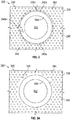
- FIGS. 5A-5B schematic illustrations of a combustor panel 526 formed in accordance with an embodiment of the present disclosure are shown.
- FIG. 5A is a detailed illustration of a pin array arrangement in proximity to a structural protrusion 544 of the combustor panel 526 and
- FIG. 5B is a schematic illustration of airflow along a cold side of the combustor panel 526 having a pin array and structural protrusion 544 in accordance with an embodiment of the present disclosure.
- the combustor panel 526 includes a plurality of cooling pins 540 formed in a pin array, with the cooling pins 540 each being separated from adjacent cooling pins 540 by a pin array separation distance, as shown and described above.
- the structural protrusion 544 is formed with a plurality of pin array extensions 558.
- the pin array extensions 558 are radial extensions of the material of the structural protrusion 544 along a cold side 538 of the combustor panel 526.
- the location of the pin array extensions 558 are designed to substantially match or fit the pin array of the cooling pins 540. That is, at locations where a cooling pin 540 would have been within the minimum separation distance (e.g., ⁇ ⁇ ⁇ 2 + ⁇ ) , the cooling pin is omitted and a pin array extension 558 is formed extending from the structural protrusion 544.
- the pin array extensions 558 are shaped and sized such that no portion of the pin array extension 558 is closer to an adjacent cooling pin 540 than the pin array separation distance (e.g., pin array separation distance ⁇ shown in FIG. 4 ). Further, the pin array extensions 558 can include curved or contoured shapes and/or geometries to aid in airflow that flows around the structural protrusion 544 and enhances producibility.
- the structural protrusion 544 having pin array extensions 558 provides an improved cooling flow along the combustor panel 526. As shown, a more even flow distribution 560 is achieved downstream from the structural protrusions 544. That is, the pin array extensions 558 of the structural protrusions 544 fill in the voids that would have been present if the cooling pins within the minimum distance of the structural protrusion had been removed. Further, because the pin array extensions 558 are part of the structural protrusion 544 (e.g., integrally formed therewith) no flashing will occur during a manufacturing process.
- the combustor panel 526 in some embodiments, is formed from a mold with liquid metal poured into the mold. Typically, this molding process can cause the flashing described above. However, because the molds can be formed to have the shape/geometry pin array extensions around the molds for the structural protrusions, no flashing may occur and improved casting processes can be achieved. Accordingly, embodiments of the present disclosure are directed to molds for forming combustor panels as described herein. As will be appreciated by those of skill in the art, the molds are "negatives" of the combustor panels illustrated herein. Thus, for example referring to FIG. 5A , a mold used to form the combustor panel 526 would include cavities for each cooling pin 540 and a cavity for the structural protrusion 544 having the pin array extensions 558.
Landscapes
- Engineering & Computer Science (AREA)
- Chemical & Material Sciences (AREA)
- Combustion & Propulsion (AREA)
- Mechanical Engineering (AREA)
- General Engineering & Computer Science (AREA)
- Turbine Rotor Nozzle Sealing (AREA)
Claims (11)
- Panneau de chambre de combustion (126, 128) destiné à être utilisé dans un moteur à turbine à gaz comprenant :un corps de panneau (136) présentant un premier côté (138) et un second côté (137) ;une pluralité de tiges de refroidissement (140 ; 240 ; 340 ; 440) s'étendant depuis le premier côté, la pluralité de tiges de refroidissement étant agencées dans une configuration de réseau de tiges, dans lequel chaque tige de refroidissement s'étend sur une première hauteur (H1) depuis le premier côté du corps de panneau, présente un diamètre de tige (β), et est séparée des tiges de refroidissement adjacentes du réseau de tiges par une distance de séparation de réseau de tiges (α) ; au moins une saillie structurelle (144 ; 244 ; 344 ; 444 ; 544) s'étendant depuis le premier côté du corps de panneau,dans lequel aucune tige de refroidissement du réseau de tiges n'est située à une position dans une distance de clignotement (µ) qui est égale à une distance de séparation de saillie (γ) plus une moitié du diamètre de tige, dans lequel la distance de séparation de saillie est une distance minimale prédéterminée entre une surface extérieure (454) de l'au moins une saillie structurelle et une surface extérieure (456) d'une tige de refroidissement, et dans lequel un emplacement de la tige de refroidissement est mesuré à partir d'un point central (452) de la tige de refroidissement jusqu'à un point le plus proche sur la surface extérieure de l'au moins une saillie structurelle dans lequel la distance de clignotement est une distance à laquelle un clignotement peut se produire pendant un processus de fabrication par moulage ; etcaractérisé en ce que le panneau de chambre de combustion comprend en outre une pluralité d'extensions de réseau de tiges (558) formées d'un seul tenant avec l'au moins une saillie structurelle (544), dans lequel les extensions de réseau de tiges sont des extensions radiales de matériau de l'au moins une saillie structurelle qui s'étendent, de manière intermittente autour de l'au moins une saillie structurelle, radialement depuis la surface extérieure de l'au moins une saillie structurelle vers des positions qui remplacent les tiges de refroidissement de la configuration de réseau de tiges qui auraient été dans la distance de clignotement, les extensions de réseau de tiges reproduisant ainsi la configuration de réseau de tiges dans les zones où le clignotement a pu se produire, dans lequel les extensions de réseau de tiges sont formées et dimensionnées de sorte qu'aucune partie des extensions de réseau de tiges n'est plus proche d'une tige de refroidissement adjacente que la distance de séparation de réseau de tiges.
- Panneau de chambre de combustion selon la revendication 1, dans lequel l'au moins une saillie structurelle (144 ; 244 ; 344 ; 444 ; 544) s'étend depuis le premier côté (138) sur une distance supérieure à la première hauteur (H1).
- Panneau de chambre de combustion selon la revendication 1 ou 2, dans lequel l'au moins une saillie structurelle est au moins l'un parmi un bossage de trou de dilution (144 ; 244 ; 344 ; 444 ; 544) et un mécanisme de fixation (132).
- Panneau de chambre de combustion selon une quelconque revendication précédente, dans lequel la distance de séparation de réseau de tiges (α) est comprise entre 0,25 mm (0,010 pouce) et 0,4 mm (0,015 pouce).
- Panneau de chambre de combustion selon la revendication 4, dans lequel la distance de séparation de réseau de tiges est de 0,33 mm (0,013 pouce).
- Chambre de combustion (102) pour un moteur à turbine à gaz (20), la chambre de combustion comprenant :une enveloppe de chambre de combustion (130) ; etau moins un panneau de chambre de combustion selon une quelconque revendication précédente monté sur l'enveloppe de chambre de combustion.
- Chambre de combustion selon la revendication 6, dans laquelle l'au moins une saillie structurelle est un bossage de trou de dilution (144 ; 244 ; 344 ; 444 ; 544) agencé pour permettre à l'air de dilution de passer à travers l'enveloppe de chambre de combustion et le panneau de chambre de combustion dans une chambre de combustion.
- Chambre de combustion selon la revendication 6, dans laquelle l'au moins une saillie structurelle est un mécanisme de fixation (132), dans laquelle le mécanisme de fixation fixe solidement l'au moins un panneau de chambre de combustion à l'enveloppe de chambre de combustion.
- Chambre de combustion selon la revendication 6, 7 ou 8, dans laquelle l'au moins un panneau de chambre de combustion (126, 128) est positionné avec le second côté (137) exposé à une chambre de combustion (104) et un flux de refroidissement (348) passe entre l'enveloppe de chambre de combustion et l'au moins un panneau de chambre de combustion le long du premier côté (138), dans laquelle le réseau de tiges assure un transfert thermique entre l'au moins un panneau de chambre de combustion et le flux de refroidissement.
- Chambre de combustion selon la revendication 9, dans laquelle les extensions de réseau de tiges modifient le flux de refroidissement (348) autour de l'au moins une saillie structurelle pour empêcher les zones chaudes (350) sur l'au moins un panneau de chambre de combustion (126, 128) à des emplacements en aval de l'au moins une saillie structurelle dans une direction d'écoulement du flux de refroidissement.
- Chambre de combustion selon l'une quelconque des revendications 6 à 10, dans laquelle l'au moins un panneau de chambre de combustion est un panneau de chambre de combustion à paroi flottante.
Applications Claiming Priority (1)
| Application Number | Priority Date | Filing Date | Title |
|---|---|---|---|
| US15/795,301 US10563584B2 (en) | 2017-10-27 | 2017-10-27 | Float wall combustor panels having airflow distribution features |
Publications (2)
| Publication Number | Publication Date |
|---|---|
| EP3477202A1 EP3477202A1 (fr) | 2019-05-01 |
| EP3477202B1 true EP3477202B1 (fr) | 2021-03-24 |
Family
ID=64051464
Family Applications (1)
| Application Number | Title | Priority Date | Filing Date |
|---|---|---|---|
| EP18202988.4A Active EP3477202B1 (fr) | 2017-10-27 | 2018-10-26 | Panneaux de chambre de combustion à paroi flotante présentant des caractéristiques de distribution de flux d'air |
Country Status (2)
| Country | Link |
|---|---|
| US (1) | US10563584B2 (fr) |
| EP (1) | EP3477202B1 (fr) |
Families Citing this family (3)
| Publication number | Priority date | Publication date | Assignee | Title |
|---|---|---|---|---|
| US11306918B2 (en) * | 2018-11-02 | 2022-04-19 | Chromalloy Gas Turbine Llc | Turbulator geometry for a combustion liner |
| CN114263933B (zh) * | 2022-03-02 | 2022-07-08 | 成都中科翼能科技有限公司 | 一种燃气轮机的组合式多通道扩压器及其扩压进气结构 |
| US12060995B1 (en) | 2023-03-22 | 2024-08-13 | General Electric Company | Turbine engine combustor with a dilution passage |
Family Cites Families (7)
| Publication number | Priority date | Publication date | Assignee | Title |
|---|---|---|---|---|
| US5220795A (en) | 1991-04-16 | 1993-06-22 | General Electric Company | Method and apparatus for injecting dilution air |
| US5601399A (en) | 1996-05-08 | 1997-02-11 | Alliedsignal Inc. | Internally cooled gas turbine vane |
| US8113441B2 (en) | 2006-09-15 | 2012-02-14 | Koppers Delaware, Inc. | Lap joint |
| US9133715B2 (en) | 2006-09-20 | 2015-09-15 | United Technologies Corporation | Structural members in a pedestal array |
| US7681398B2 (en) | 2006-11-17 | 2010-03-23 | Pratt & Whitney Canada Corp. | Combustor liner and heat shield assembly |
| US9322560B2 (en) * | 2012-09-28 | 2016-04-26 | United Technologies Corporation | Combustor bulkhead assembly |
| US10267520B2 (en) | 2017-08-11 | 2019-04-23 | United Technologies Corporation | Float wall combustor panels having airflow distribution features |
-
2017
- 2017-10-27 US US15/795,301 patent/US10563584B2/en active Active
-
2018
- 2018-10-26 EP EP18202988.4A patent/EP3477202B1/fr active Active
Non-Patent Citations (1)
| Title |
|---|
| None * |
Also Published As
| Publication number | Publication date |
|---|---|
| US10563584B2 (en) | 2020-02-18 |
| US20190128187A1 (en) | 2019-05-02 |
| EP3477202A1 (fr) | 2019-05-01 |
Similar Documents
| Publication | Publication Date | Title |
|---|---|---|
| EP3366995B1 (fr) | Assemblage de panneau de chambre de combustion et procédé pour son refroidissement | |
| EP3447384B1 (fr) | Agencements de refroidissement de panneau de chambre de combustion | |
| US11156359B2 (en) | Combustor liner panel end rail with diffused interface passage for a gas turbine engine combustor | |
| EP3090209B1 (fr) | Passe-fil refroidi pour un ensemble paroi de chambre de combustion de turbine à gaz | |
| EP3366998B1 (fr) | Chambre de combustion comprenant des panneaux de revêtement et des rails d'extrémité avec un passage d'interface courbe pour un moteur à turbine à gaz | |
| EP3366997B1 (fr) | Caractéristiques d'amélioration de refroidissement de rail d'extrémité de panneau de chemise de chambre de combustion pour une chambre de combustion de turbine à gaz | |
| EP3361158B1 (fr) | Chambre de combustion pour une turbine à gaz | |
| EP3441673B1 (fr) | Panneaux de chambre de combustion présentant des caractéristiques de distribution de flux d'air | |
| EP3330611B1 (fr) | Panneau de chemise de chambre de combustion régulée pour chambre de combustion de turbine à gaz | |
| EP3477202B1 (fr) | Panneaux de chambre de combustion à paroi flotante présentant des caractéristiques de distribution de flux d'air | |
| EP3047111B1 (fr) | Composant de moteur à turbine à gaz, moteur à turbine à gaz et procédé de refroidissement associés | |
| EP3453970A2 (fr) | Panneaux de chambre de combustion à paroi flottante présentant une augmentation du transfert de chaleur | |
| EP3084307B1 (fr) | Agencement de passage d'apport d'air pour chambre de combustion de moteur à turbine à gaz | |
| EP3321584B1 (fr) | Chambre de combustion de turbine à gaz avec un panneau de chemise de chambre de combustion axialment non-plan | |
| EP3321585B1 (fr) | Panneau de chemise de chambre de combustion non plane pour chambre de combustion de turbine à gaz | |
| EP4328488B1 (fr) | Chambre de combustion pour turbine à gaz avec panneau de revêtement avec porte arrondie | |
| EP3748133B1 (fr) | Joint à air extérieur d'aube résistant à la fatigue | |
| EP3318803B1 (fr) | Arrangement de barres de renforcement pour chambre de combustion de moteur de turbine à gaz | |
| EP3321588B1 (fr) | Chambre de combustion pour un moteur de turbine à gaz | |
| EP3315862B1 (fr) | Panneau de revêtement moulé de chambre de combustion comportant un bord a rayon pour chambre de combustion de turbine à gaz |
Legal Events
| Date | Code | Title | Description |
|---|---|---|---|
| PUAI | Public reference made under article 153(3) epc to a published international application that has entered the european phase |
Free format text: ORIGINAL CODE: 0009012 |
|
| STAA | Information on the status of an ep patent application or granted ep patent |
Free format text: STATUS: THE APPLICATION HAS BEEN PUBLISHED |
|
| AK | Designated contracting states |
Kind code of ref document: A1 Designated state(s): AL AT BE BG CH CY CZ DE DK EE ES FI FR GB GR HR HU IE IS IT LI LT LU LV MC MK MT NL NO PL PT RO RS SE SI SK SM TR |
|
| AX | Request for extension of the european patent |
Extension state: BA ME |
|
| STAA | Information on the status of an ep patent application or granted ep patent |
Free format text: STATUS: REQUEST FOR EXAMINATION WAS MADE |
|
| 17P | Request for examination filed |
Effective date: 20191030 |
|
| RBV | Designated contracting states (corrected) |
Designated state(s): AL AT BE BG CH CY CZ DE DK EE ES FI FR GB GR HR HU IE IS IT LI LT LU LV MC MK MT NL NO PL PT RO RS SE SI SK SM TR |
|
| GRAP | Despatch of communication of intention to grant a patent |
Free format text: ORIGINAL CODE: EPIDOSNIGR1 |
|
| STAA | Information on the status of an ep patent application or granted ep patent |
Free format text: STATUS: GRANT OF PATENT IS INTENDED |
|
| INTG | Intention to grant announced |
Effective date: 20201008 |
|
| RIN1 | Information on inventor provided before grant (corrected) |
Inventor name: HOKE, JAMES B. Inventor name: SONNTAG, ROBERT M. Inventor name: ULLRICH, RICHARD G. Inventor name: QUACH, SAN Inventor name: SHENNY, JASON Inventor name: RUP, JOHN J. |
|
| GRAS | Grant fee paid |
Free format text: ORIGINAL CODE: EPIDOSNIGR3 |
|
| GRAA | (expected) grant |
Free format text: ORIGINAL CODE: 0009210 |
|
| STAA | Information on the status of an ep patent application or granted ep patent |
Free format text: STATUS: THE PATENT HAS BEEN GRANTED |
|
| AK | Designated contracting states |
Kind code of ref document: B1 Designated state(s): AL AT BE BG CH CY CZ DE DK EE ES FI FR GB GR HR HU IE IS IT LI LT LU LV MC MK MT NL NO PL PT RO RS SE SI SK SM TR |
|
| RAP1 | Party data changed (applicant data changed or rights of an application transferred) |
Owner name: RAYTHEON TECHNOLOGIES CORPORATION |
|
| REG | Reference to a national code |
Ref country code: GB Ref legal event code: FG4D |
|
| REG | Reference to a national code |
Ref country code: CH Ref legal event code: EP |
|
| REG | Reference to a national code |
Ref country code: IE Ref legal event code: FG4D |
|
| REG | Reference to a national code |
Ref country code: AT Ref legal event code: REF Ref document number: 1374851 Country of ref document: AT Kind code of ref document: T Effective date: 20210415 Ref country code: DE Ref legal event code: R096 Ref document number: 602018014312 Country of ref document: DE |
|
| REG | Reference to a national code |
Ref country code: LT Ref legal event code: MG9D |
|
| PG25 | Lapsed in a contracting state [announced via postgrant information from national office to epo] |
Ref country code: HR Free format text: LAPSE BECAUSE OF FAILURE TO SUBMIT A TRANSLATION OF THE DESCRIPTION OR TO PAY THE FEE WITHIN THE PRESCRIBED TIME-LIMIT Effective date: 20210324 Ref country code: GR Free format text: LAPSE BECAUSE OF FAILURE TO SUBMIT A TRANSLATION OF THE DESCRIPTION OR TO PAY THE FEE WITHIN THE PRESCRIBED TIME-LIMIT Effective date: 20210625 Ref country code: FI Free format text: LAPSE BECAUSE OF FAILURE TO SUBMIT A TRANSLATION OF THE DESCRIPTION OR TO PAY THE FEE WITHIN THE PRESCRIBED TIME-LIMIT Effective date: 20210324 Ref country code: BG Free format text: LAPSE BECAUSE OF FAILURE TO SUBMIT A TRANSLATION OF THE DESCRIPTION OR TO PAY THE FEE WITHIN THE PRESCRIBED TIME-LIMIT Effective date: 20210624 Ref country code: NO Free format text: LAPSE BECAUSE OF FAILURE TO SUBMIT A TRANSLATION OF THE DESCRIPTION OR TO PAY THE FEE WITHIN THE PRESCRIBED TIME-LIMIT Effective date: 20210624 |
|
| PG25 | Lapsed in a contracting state [announced via postgrant information from national office to epo] |
Ref country code: SE Free format text: LAPSE BECAUSE OF FAILURE TO SUBMIT A TRANSLATION OF THE DESCRIPTION OR TO PAY THE FEE WITHIN THE PRESCRIBED TIME-LIMIT Effective date: 20210324 Ref country code: RS Free format text: LAPSE BECAUSE OF FAILURE TO SUBMIT A TRANSLATION OF THE DESCRIPTION OR TO PAY THE FEE WITHIN THE PRESCRIBED TIME-LIMIT Effective date: 20210324 Ref country code: LV Free format text: LAPSE BECAUSE OF FAILURE TO SUBMIT A TRANSLATION OF THE DESCRIPTION OR TO PAY THE FEE WITHIN THE PRESCRIBED TIME-LIMIT Effective date: 20210324 |
|
| REG | Reference to a national code |
Ref country code: NL Ref legal event code: MP Effective date: 20210324 |
|
| REG | Reference to a national code |
Ref country code: AT Ref legal event code: MK05 Ref document number: 1374851 Country of ref document: AT Kind code of ref document: T Effective date: 20210324 |
|
| PG25 | Lapsed in a contracting state [announced via postgrant information from national office to epo] |
Ref country code: NL Free format text: LAPSE BECAUSE OF FAILURE TO SUBMIT A TRANSLATION OF THE DESCRIPTION OR TO PAY THE FEE WITHIN THE PRESCRIBED TIME-LIMIT Effective date: 20210324 |
|
| PG25 | Lapsed in a contracting state [announced via postgrant information from national office to epo] |
Ref country code: CZ Free format text: LAPSE BECAUSE OF FAILURE TO SUBMIT A TRANSLATION OF THE DESCRIPTION OR TO PAY THE FEE WITHIN THE PRESCRIBED TIME-LIMIT Effective date: 20210324 Ref country code: EE Free format text: LAPSE BECAUSE OF FAILURE TO SUBMIT A TRANSLATION OF THE DESCRIPTION OR TO PAY THE FEE WITHIN THE PRESCRIBED TIME-LIMIT Effective date: 20210324 Ref country code: LT Free format text: LAPSE BECAUSE OF FAILURE TO SUBMIT A TRANSLATION OF THE DESCRIPTION OR TO PAY THE FEE WITHIN THE PRESCRIBED TIME-LIMIT Effective date: 20210324 Ref country code: AT Free format text: LAPSE BECAUSE OF FAILURE TO SUBMIT A TRANSLATION OF THE DESCRIPTION OR TO PAY THE FEE WITHIN THE PRESCRIBED TIME-LIMIT Effective date: 20210324 Ref country code: SM Free format text: LAPSE BECAUSE OF FAILURE TO SUBMIT A TRANSLATION OF THE DESCRIPTION OR TO PAY THE FEE WITHIN THE PRESCRIBED TIME-LIMIT Effective date: 20210324 |
|
| PG25 | Lapsed in a contracting state [announced via postgrant information from national office to epo] |
Ref country code: IS Free format text: LAPSE BECAUSE OF FAILURE TO SUBMIT A TRANSLATION OF THE DESCRIPTION OR TO PAY THE FEE WITHIN THE PRESCRIBED TIME-LIMIT Effective date: 20210724 Ref country code: SK Free format text: LAPSE BECAUSE OF FAILURE TO SUBMIT A TRANSLATION OF THE DESCRIPTION OR TO PAY THE FEE WITHIN THE PRESCRIBED TIME-LIMIT Effective date: 20210324 Ref country code: RO Free format text: LAPSE BECAUSE OF FAILURE TO SUBMIT A TRANSLATION OF THE DESCRIPTION OR TO PAY THE FEE WITHIN THE PRESCRIBED TIME-LIMIT Effective date: 20210324 Ref country code: PT Free format text: LAPSE BECAUSE OF FAILURE TO SUBMIT A TRANSLATION OF THE DESCRIPTION OR TO PAY THE FEE WITHIN THE PRESCRIBED TIME-LIMIT Effective date: 20210726 Ref country code: PL Free format text: LAPSE BECAUSE OF FAILURE TO SUBMIT A TRANSLATION OF THE DESCRIPTION OR TO PAY THE FEE WITHIN THE PRESCRIBED TIME-LIMIT Effective date: 20210324 |
|
| REG | Reference to a national code |
Ref country code: DE Ref legal event code: R097 Ref document number: 602018014312 Country of ref document: DE |
|
| PG25 | Lapsed in a contracting state [announced via postgrant information from national office to epo] |
Ref country code: ES Free format text: LAPSE BECAUSE OF FAILURE TO SUBMIT A TRANSLATION OF THE DESCRIPTION OR TO PAY THE FEE WITHIN THE PRESCRIBED TIME-LIMIT Effective date: 20210324 Ref country code: AL Free format text: LAPSE BECAUSE OF FAILURE TO SUBMIT A TRANSLATION OF THE DESCRIPTION OR TO PAY THE FEE WITHIN THE PRESCRIBED TIME-LIMIT Effective date: 20210324 Ref country code: DK Free format text: LAPSE BECAUSE OF FAILURE TO SUBMIT A TRANSLATION OF THE DESCRIPTION OR TO PAY THE FEE WITHIN THE PRESCRIBED TIME-LIMIT Effective date: 20210324 |
|
| PLBE | No opposition filed within time limit |
Free format text: ORIGINAL CODE: 0009261 |
|
| STAA | Information on the status of an ep patent application or granted ep patent |
Free format text: STATUS: NO OPPOSITION FILED WITHIN TIME LIMIT |
|
| PG25 | Lapsed in a contracting state [announced via postgrant information from national office to epo] |
Ref country code: SI Free format text: LAPSE BECAUSE OF FAILURE TO SUBMIT A TRANSLATION OF THE DESCRIPTION OR TO PAY THE FEE WITHIN THE PRESCRIBED TIME-LIMIT Effective date: 20210324 |
|
| 26N | No opposition filed |
Effective date: 20220104 |
|
| PG25 | Lapsed in a contracting state [announced via postgrant information from national office to epo] |
Ref country code: IS Free format text: LAPSE BECAUSE OF FAILURE TO SUBMIT A TRANSLATION OF THE DESCRIPTION OR TO PAY THE FEE WITHIN THE PRESCRIBED TIME-LIMIT Effective date: 20210724 |
|
| REG | Reference to a national code |
Ref country code: CH Ref legal event code: PL |
|
| REG | Reference to a national code |
Ref country code: BE Ref legal event code: MM Effective date: 20211031 |
|
| PG25 | Lapsed in a contracting state [announced via postgrant information from national office to epo] |
Ref country code: MC Free format text: LAPSE BECAUSE OF FAILURE TO SUBMIT A TRANSLATION OF THE DESCRIPTION OR TO PAY THE FEE WITHIN THE PRESCRIBED TIME-LIMIT Effective date: 20210324 |
|
| PG25 | Lapsed in a contracting state [announced via postgrant information from national office to epo] |
Ref country code: LU Free format text: LAPSE BECAUSE OF NON-PAYMENT OF DUE FEES Effective date: 20211026 Ref country code: BE Free format text: LAPSE BECAUSE OF NON-PAYMENT OF DUE FEES Effective date: 20211031 |
|
| PG25 | Lapsed in a contracting state [announced via postgrant information from national office to epo] |
Ref country code: LI Free format text: LAPSE BECAUSE OF NON-PAYMENT OF DUE FEES Effective date: 20211031 Ref country code: CH Free format text: LAPSE BECAUSE OF NON-PAYMENT OF DUE FEES Effective date: 20211031 |
|
| PG25 | Lapsed in a contracting state [announced via postgrant information from national office to epo] |
Ref country code: IE Free format text: LAPSE BECAUSE OF NON-PAYMENT OF DUE FEES Effective date: 20211026 |
|
| PG25 | Lapsed in a contracting state [announced via postgrant information from national office to epo] |
Ref country code: IT Free format text: LAPSE BECAUSE OF FAILURE TO SUBMIT A TRANSLATION OF THE DESCRIPTION OR TO PAY THE FEE WITHIN THE PRESCRIBED TIME-LIMIT Effective date: 20210324 |
|
| P01 | Opt-out of the competence of the unified patent court (upc) registered |
Effective date: 20230521 |
|
| PG25 | Lapsed in a contracting state [announced via postgrant information from national office to epo] |
Ref country code: CY Free format text: LAPSE BECAUSE OF FAILURE TO SUBMIT A TRANSLATION OF THE DESCRIPTION OR TO PAY THE FEE WITHIN THE PRESCRIBED TIME-LIMIT Effective date: 20210324 |
|
| PG25 | Lapsed in a contracting state [announced via postgrant information from national office to epo] |
Ref country code: HU Free format text: LAPSE BECAUSE OF FAILURE TO SUBMIT A TRANSLATION OF THE DESCRIPTION OR TO PAY THE FEE WITHIN THE PRESCRIBED TIME-LIMIT; INVALID AB INITIO Effective date: 20181026 |
|
| PG25 | Lapsed in a contracting state [announced via postgrant information from national office to epo] |
Ref country code: MK Free format text: LAPSE BECAUSE OF FAILURE TO SUBMIT A TRANSLATION OF THE DESCRIPTION OR TO PAY THE FEE WITHIN THE PRESCRIBED TIME-LIMIT Effective date: 20210324 |
|
| PG25 | Lapsed in a contracting state [announced via postgrant information from national office to epo] |
Ref country code: MT Free format text: LAPSE BECAUSE OF FAILURE TO SUBMIT A TRANSLATION OF THE DESCRIPTION OR TO PAY THE FEE WITHIN THE PRESCRIBED TIME-LIMIT Effective date: 20210324 |
|
| REG | Reference to a national code |
Ref country code: DE Ref legal event code: R081 Ref document number: 602018014312 Country of ref document: DE Owner name: RTX CORPORATION (N.D.GES.D. STAATES DELAWARE),, US Free format text: FORMER OWNER: RAYTHEON TECHNOLOGIES CORPORATION, FARMINGTON, CT, US |
|
| PGFP | Annual fee paid to national office [announced via postgrant information from national office to epo] |
Ref country code: GB Payment date: 20250923 Year of fee payment: 8 |
|
| PGFP | Annual fee paid to national office [announced via postgrant information from national office to epo] |
Ref country code: FR Payment date: 20250924 Year of fee payment: 8 |
|
| PG25 | Lapsed in a contracting state [announced via postgrant information from national office to epo] |
Ref country code: TR Free format text: LAPSE BECAUSE OF FAILURE TO SUBMIT A TRANSLATION OF THE DESCRIPTION OR TO PAY THE FEE WITHIN THE PRESCRIBED TIME-LIMIT Effective date: 20210324 |
|
| PGFP | Annual fee paid to national office [announced via postgrant information from national office to epo] |
Ref country code: DE Payment date: 20250923 Year of fee payment: 8 |