EP3477209B1 - Four comportant un dispositif d'imagerie - Google Patents
Four comportant un dispositif d'imagerie Download PDFInfo
- Publication number
- EP3477209B1 EP3477209B1 EP18202999.1A EP18202999A EP3477209B1 EP 3477209 B1 EP3477209 B1 EP 3477209B1 EP 18202999 A EP18202999 A EP 18202999A EP 3477209 B1 EP3477209 B1 EP 3477209B1
- Authority
- EP
- European Patent Office
- Prior art keywords
- oven
- imaging device
- camera
- channel
- cooking cavity
- Prior art date
- Legal status (The legal status is an assumption and is not a legal conclusion. Google has not performed a legal analysis and makes no representation as to the accuracy of the status listed.)
- Active
Links
Images


Classifications
-
- F—MECHANICAL ENGINEERING; LIGHTING; HEATING; WEAPONS; BLASTING
- F27—FURNACES; KILNS; OVENS; RETORTS
- F27D—DETAILS OR ACCESSORIES OF FURNACES, KILNS, OVENS OR RETORTS, IN SO FAR AS THEY ARE OF KINDS OCCURRING IN MORE THAN ONE KIND OF FURNACE
- F27D21/00—Arrangement of monitoring devices; Arrangement of safety devices
- F27D21/02—Observation or illuminating devices
-
- F—MECHANICAL ENGINEERING; LIGHTING; HEATING; WEAPONS; BLASTING
- F24—HEATING; RANGES; VENTILATING
- F24C—DOMESTIC STOVES OR RANGES ; DETAILS OF DOMESTIC STOVES OR RANGES, OF GENERAL APPLICATION
- F24C15/00—Details
- F24C15/008—Illumination for oven cavities
-
- F—MECHANICAL ENGINEERING; LIGHTING; HEATING; WEAPONS; BLASTING
- F24—HEATING; RANGES; VENTILATING
- F24C—DOMESTIC STOVES OR RANGES ; DETAILS OF DOMESTIC STOVES OR RANGES, OF GENERAL APPLICATION
- F24C15/00—Details
- F24C15/34—Elements and arrangements for heat storage or insulation
-
- F—MECHANICAL ENGINEERING; LIGHTING; HEATING; WEAPONS; BLASTING
- F27—FURNACES; KILNS; OVENS; RETORTS
- F27D—DETAILS OR ACCESSORIES OF FURNACES, KILNS, OVENS OR RETORTS, IN SO FAR AS THEY ARE OF KINDS OCCURRING IN MORE THAN ONE KIND OF FURNACE
- F27D21/00—Arrangement of monitoring devices; Arrangement of safety devices
- F27D21/02—Observation or illuminating devices
- F27D2021/026—Observation or illuminating devices using a video installation
Definitions
- a kitchen appliance such as an oven
- the user desires to monitor the progress of the contents while being cooked.
- ovens and other cooking appliances include doors providing access to the cooking cavity having transparent windows and a light within the cooking cavity to illuminate the contents in order to monitor the progress of the contents being cooked through the window.
- the windows on the door only provide one view of the contents to be cooked.
- a user will need to open the door and pull out the contents to be cooked in order to view the top or another side of the contents to be cooked that is not visible through the window. Opening the door can cause a drop in temperature of the oven and can affect cooking time and quality of the contents to be cooked.
- Document WO2016/196669 upon the disclosure of which the preamble of claim 1 is drafted, discloses an oven comprising a camera assembly for real-time food stuff identification can be arranged within an oven top fluid cooling channel that enables ambient air to cool the camera assembly.
- Document EP1601236 discloses a cooking device having induction heating zones, comprising a heat pipe to cool power electronic units for induction cooking.
- Document EP2520169 discloses an oven door adapted to be attached to a baking oven, comprising an outer wall and an inner wall and at least one image recording device mounted therebetween. Further relevant prior art is found in DE 10 2011 088087 A1 , WO 2016/128372 A1 and EP 2 639 514 A1 .
- the present disclosure relates to an oven including an oven body having a peripheral wall at least partially defining a cooking cavity with a top wall comprising spaced interior panels and exterior panels defining a channel therebetween, insulation located in the channel, and an imaging device mounted in the channel in thermal engagement with the insulation with a field of view including at least a portion of the cooking cavity.
- An oven includes a camera housed within walls of a cooking cavity with a field of view that passes through at least a portion of the cooking cavity. Contents to be cooked are located within the cooking cavity such that the camera can image the contents.
- a thermal management system is provided to insulate, cool and otherwise protect the camera from the heat of the oven cavity during operation.
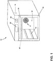
- FIG. 1 is a perspective view of an oven 10.
- the oven 10 described herein shares many features of a traditional oven, which will not be described in detail except as necessary for a complete understanding of the invention. While the embodiments of the invention are described in the context of an oven 10, the embodiments of the invention may be used with any type of cooking appliance, non-limiting examples of which include a convection oven, a steam oven, a toaster oven, and a microwave.
- the oven 10 can include a door 30 having a handle 38 and is moveable between open and closed positions. As illustrated, the door 30 is in the closed position. The door 30 can form part of a cooking cavity 32 when the door 30 is in the closed position.
- the cooking cavity 32 can include a fan 11 and rack mounts 19 configured to hold rack inserts (not shown) such that contents to be cooked within the cooking cavity 32 can be placed on the racks inserts.
- the oven 10 includes an imaging device 40 for imaging the contents to be cooked.
- the imaging device 40 can be in the form of a camera, or any other suitable imaging device.
- a display such as an LCD screen 60, can be provided on the oven 10 and can be in communication with the camera 40 where the LCD screen 60 can display images captured by the camera 40.
- the image output by the camera 40 can be a real-time representation of the contents being cooked to allow a user to monitor the contents using the LCD screen 60 without the need for opening the door 30.
- the oven 10 can include a user interface 62.
- the user interface 62 can include operational controls such as dials, lights, knobs, levers, buttons, switches, and displays enabling the user to input commands to a controller 70 to operate the oven 10 and to receive information about an operational status of the oven 10. While the LCD screen 60 and the user interface 62 are shown as separate components, it is possible that the LCD screen 60 and the user interface 62 are combined into one component.
- FIG. 2 is a schematic view of the controller 70 coupled to the various components of the oven 10.
- the controller 70 may be communicably coupled to components of the oven 10 such as a heating element 64, the fan 11, the user interface 62, the camera 40, and the display 60 to either control these components and/or receive their input for use in controlling the components.
- the controller 70 can implement a heating cycle selected by the user according to any options selected by the user and provide related information to the user.
- the controller 70 can also include a central processing unit (CPU) 74 and an associated memory 72 where various operational procedures may be stored.
- One or more software applications such as an arrangement of executable commands/instructions may be stored in the memory 72 and executed by the CPU 74 to implement the operational procedures.
- the controller 70 can be in communication with the camera 40 such that the images can be output by the camera 40 and input to the controller 70.
- the controller 70 can output the images to the display 60 or another display, such as a mobile device display in order for a user to remotely monitor the contents being cooked.
- the camera 40 can also include a controller 43 that can include a CPU 46 and an associated memory 48.
- the controller 43 or the controller 70 can be in communication with a network 80, such as the internet.
- the network 80 can include wired, wireless, or a combination of wired and wireless points or nodes to connect communication paths for exchanging and transporting data.
- the images from the camera 40 can be sent to a mobile device via the network 80 from either controller 43 or 70.
- the camera 40 can be directly coupled to the controller 70 or indirectly coupled to the controller 70 via the network 80.
- the camera 40 can include an image recognition algorithm 76 that can be implemented as a program in the controller 43 wherein blurry images taken by the camera 40 are detected.
- the image recognition algorithm 76 can also decide to discard blurry images such that the blurry images are not output by the camera 40.
- the camera 40 can include a deblurring image algorithm 78 that can also be implemented as a program in the controller 43.
- the deblurring image algorithm 78 can correct blurry images detected by the image recognition algorithm 76.
- the deblurring image algorithm 78 can also be implemented in a cloud in the network 80, wherein the network 80 can communicate output from the deblurring image algorithm 78 to the controller 70.
- the oven body 12 can include a pair of peripheral walls 14, a top wall 16, and a bottom wall 15.
- a rear wall 17 can couple the peripheral walls 14, the top wall 16, and the bottom wall 15 and partially define the cooking cavity 32.
- An inner top edge 24 can be defined where the top wall 16 meets either of the peripheral walls 14.
- the top wall 16, the peripheral walls 14, and the bottom wall 15 can include an interior panel 18 spaced from an exterior panel 20.
- the panels 18, 20 can be made of any suitable material, such as metal, to withstand heat from the cooking cavity 32.
- a channel 22 is defined by the space between the interior panel 18 and the exterior panel 20 and includes insulation 23 located within the channel 22.
- the insulation 23 can be provided to insulate the cooking cavity 32 to prevent loss of heat for more efficient cooking.
- the camera 40 is mounted within the channel 22 and is in thermal engagement with the insulation 23 to help keep the camera insulated from oven heat when in operation.
- the camera 40 can be embedded within the insulation 23 and can be positioned such that the camera 40 having a lens 41 has a field of view 42 directed into the cooking cavity 32 including at least a portion of the cooking cavity 32.
- the camera 40 can be mounted in the upper front corner 25 of the oven cavity or in nearly any location along the inner top edge 24.
- the camera 40 can include a stand or feet to create a space between the camera 40 and the interior panel 18, such that the camera 40 is raised and does not rest directly on the interior panel 18.
- the interior panel 18 can include an aperture 44.
- the aperture 44 can include a clear cover, which can be in the form of glass, or any other suitable transparent material to enable the field of view 42 to pass into the cooking cavity 32 and to seal the space in the interior panel 18 formed by the aperture 44.
- the cover can include a single layer of glass or multiple layers of glass where the cover is disposed between the interior panel 18 and the camera 40. A single or multiple layers of glass can provide additional insulation for the camera 40 and lens 41.
- the camera 40 can include a damper coupled with the oven body 12 to control and absorb mechanical vibrations in the oven 10.
- the damper can be in the form of a heat resistant rubber or foam that can be disposed around the entire camera 40 or a portion of the camera 40.
- Mechanical vibrations can include vibrations from a fan, such as the fan 11, or airflow within the channel 22 that comes into contact with the camera 40.
- vibrations to the oven 10 can result from boiling water on the range, a user moving around pots, pans, or utensils, and the like.
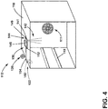
- FIG. 4 another exemplary oven body 112 is shown in more detail. Since the oven body 112 is similar to the oven body 12; like parts will be identified with like numerals increased by 100, with it being understood that the description of the like parts of oven body 12 applies to oven body 112, unless otherwise noted.
- the exterior panel and the insulation are not shown to more clearly illustrate the camera 140.
- FIG. 3 illustrates the camera in the upper front corner 25 or inner top edge 24 of the oven body 12
- the camera 140 can also be mounted in a middle portion of the inner panel 118.
- the camera 140 is coupled to a heat sink 160in order to dissipate heat from within the channel 122 away from the camera.
- the heat sink 160 is thermally or mechanically coupled to the camera 140 such that the heat sink 160 is indirectly or directly coupled to the camera 140.
- the heat sink 160 includes a heat pipe 150 having a first end 152 coupled to the camera 140 and a second end 154 spaced from the first end 154 and coupled to the heat sink.
- FIG. 4 more clearly illustrates the aperture 144 and the clear cover 149.
- An auxiliary fan 126 can be coupled with the oven body 112 and included within the channel 122 in order to direct airflow towards the camera 140 and provide a cooling effect on the camera 140. While it is contemplated the fan 126 direct toward the camera 140, the fan 126 can be also be directed toward the heat sink 160 to help further dissipate heat.
- aspects of the disclosure described herein can be used to monitor contents to be cooked during cooking in an oven without the need for opening the oven door to view additional angles of the contents to be cooked. Aspects of the disclosure can improve imaging of an oven cavity by managing heat and vibrations on the camera.
- the upper corner, or top edge of the oven body can be considered a cooler location for the camera.
- heat sinks can be used to aid in the dissipation of heat from the camera.
- aspects described herein can be used to display images of the contents to be cooked that are not blurred in order for a user to view clear images for monitoring the contents to be cooked.
- the different features and structures of the various embodiments can be used in combination with each other as desired. That one feature may not be illustrated in all of the embodiments is not meant to be construed that it may not be, but is done for brevity of description. Thus, the various features of the different embodiments can be mixed and matched as desired to form new embodiments, whether or not the new embodiments are expressly described. All combinations or permutations of features described herein are covered by this disclosure as defined by the scope of the independent claim.
- the oven body 12 in FIG. 3 can include an aperture for the camera 40. It should be appreciated that the aforementioned method can be used within alternative appliances.
Landscapes
- Engineering & Computer Science (AREA)
- Mechanical Engineering (AREA)
- General Engineering & Computer Science (AREA)
- Chemical & Material Sciences (AREA)
- Combustion & Propulsion (AREA)
- Electric Ovens (AREA)
- Electric Stoves And Ranges (AREA)
Claims (10)
- Four (10), comprenant :un corps de four (12, 112) ayant une paroi périphérique (14, 114) définissant au moins partiellement une cavité de cuisson (32, 132) avec une paroi de sommet (16, 116) comprenant des panneaux intérieurs (18, 118) espacés et des panneaux extérieurs (20, 120) définissant un canal (22, 122) entre eux ;une isolation (23) située dans le canal (22, 122) ;un dispositif d'imagerie (40, 140) monté dans le canal (22, 122) en engagement thermique avec l'isolation (23) avec un champ de vision (42, 142) incluant au moins une portion de la cavité de cuisson (32, 132) ; etun dissipateur de chaleur (160) couplé au dispositif d'imagerie (40, 140) ;caractérisé en ce quele four (10) comprend un caloduc (150) comprenant une première extrémité (152) couplée au dispositif d'imagerie (40, 140) et une seconde extrémité (154) espacée de la première extrémité (152) couplée au caloduc (160).
- Four (10) selon la revendication 1, dans lequel le corps de four (12, 112) définit un bord de sommet intérieur (24) où le sommet (16) rejoint la paroi périphérique (14).
- Four (10) selon la revendication 2, dans lequel le dispositif d'imagerie (40, 140) est monté dans le sommet (16) le long du bord de sommet intérieur (24).
- Four (10) selon les revendications 1 à 3, comprenant en outre une ouverture (44, 144) dans le panneau intérieur (18, 118) à travers laquelle passe le champ de vision (42, 142) du dispositif d'imagerie.
- Four (10) selon l'une des revendications 1 à 4, dans lequel le dispositif d'imagerie (40, 140) est incorporé à l'intérieur de l'isolation (23) qui est située dans le canal (22) pour isoler la cavité de cuisson (32, 132) afin d'empêcher toute perte de chaleur.
- Four (10) selon l'une des revendications 1 à 5, dans lequel le dispositif d'imagerie (40, 140) inclut un socle ou des pieds pour créer un espace entre le dispositif d'imagerie (40, 140) et un panneau intérieur desdits panneaux intérieurs (18, 118) de sorte que le dispositif d'imagerie (40, 140) soit surélevé et ne repose pas directement sur ledit panneau intérieur (18, 118).
- Four (10) selon les revendications 1 à 4, comprenant en outre un ventilateur (126) couplé au corps de four (12, 112) pour générer un flux d'air à travers une portion du canal (22, 122).
- Four (10) selon la revendication 7, dans lequel le ventilateur (126) est situé adjacent au dispositif d'imagerie (40, 140) pour diriger un flux d'air sur le dispositif d'imagerie (40, 140).
- Four (10) selon la revendication 7, dans lequel le ventilateur (126) est inclus dans le canal (22, 122).
- Four (10) selon les revendications 1 à 9, comprenant en outre une porte (30) ayant une position ouverte et une position fermée, dans lequel, à la position fermée, la porte fait partie de la cavité de cuisson (32).
Applications Claiming Priority (1)
| Application Number | Priority Date | Filing Date | Title |
|---|---|---|---|
| US15/795,597 US10591218B2 (en) | 2017-10-27 | 2017-10-27 | Oven having an imaging device |
Publications (2)
| Publication Number | Publication Date |
|---|---|
| EP3477209A1 EP3477209A1 (fr) | 2019-05-01 |
| EP3477209B1 true EP3477209B1 (fr) | 2020-04-08 |
Family
ID=64082899
Family Applications (1)
| Application Number | Title | Priority Date | Filing Date |
|---|---|---|---|
| EP18202999.1A Active EP3477209B1 (fr) | 2017-10-27 | 2018-10-26 | Four comportant un dispositif d'imagerie |
Country Status (2)
| Country | Link |
|---|---|
| US (3) | US10591218B2 (fr) |
| EP (1) | EP3477209B1 (fr) |
Families Citing this family (9)
| Publication number | Priority date | Publication date | Assignee | Title |
|---|---|---|---|---|
| US10694882B2 (en) * | 2016-02-26 | 2020-06-30 | Zezhi Intellectual Property Service | Cooking device with image detection sensor |
| JP7108820B2 (ja) * | 2018-04-27 | 2022-07-29 | パナソニックIpマネジメント株式会社 | 加熱調理器 |
| JP7198972B2 (ja) * | 2018-04-27 | 2023-01-05 | パナソニックIpマネジメント株式会社 | 加熱調理器 |
| CH717980A1 (de) * | 2020-10-19 | 2022-04-29 | V Zug Ag | Gargerät mit Kamera zur Überwachung des Garraums. |
| US12010409B2 (en) * | 2021-12-22 | 2024-06-11 | Whirlpool Corporation | Camera view port dedicated self cleaning cycles |
| WO2024053907A1 (fr) * | 2022-09-07 | 2024-03-14 | 삼성전자주식회사 | Appareil de cuisson |
| US20240125652A1 (en) * | 2022-10-14 | 2024-04-18 | Meridian Innovation Pte Ltd | Modular infrared sensor module for cooking |
| US12520024B2 (en) * | 2022-11-30 | 2026-01-06 | Bsh Home Appliances Corporation | Serviceable oven camera mount |
| DE102024209733A1 (de) * | 2024-10-04 | 2026-04-09 | BSH Hausgeräte GmbH | Gargerät mit Kühlung eines Elektronikbauteils |
Citations (3)
| Publication number | Priority date | Publication date | Assignee | Title |
|---|---|---|---|---|
| DE102011088087A1 (de) * | 2011-12-09 | 2013-06-13 | BSH Bosch und Siemens Hausgeräte GmbH | Beleuchtungsvorrichtung für ein Gargerät und Gargerät |
| EP2639514A1 (fr) * | 2012-03-14 | 2013-09-18 | BSH Bosch und Siemens Hausgeräte GmbH | Dispositif d'appareil de cuisson |
| WO2016128372A1 (fr) * | 2015-02-10 | 2016-08-18 | Electrolux Appliances Aktiebolag | Porte de four et four comprenant une porte de four |
Family Cites Families (16)
| Publication number | Priority date | Publication date | Assignee | Title |
|---|---|---|---|---|
| JP2003274235A (ja) * | 2002-03-15 | 2003-09-26 | Fuji Photo Optical Co Ltd | テレビカメラハウジング |
| DE102004025915A1 (de) | 2004-05-27 | 2005-12-22 | BSH Bosch und Siemens Hausgeräte GmbH | Gargerät mit einer Kühleinheit |
| DE102008043722A1 (de) | 2008-11-13 | 2010-05-20 | BSH Bosch und Siemens Hausgeräte GmbH | Hausgeräte-Bedienungsanordnung mit einer tragbaren Fernbedienungseinheit |
| RU2653461C2 (ru) * | 2014-01-21 | 2018-05-08 | Общество с ограниченной ответственностью "Аби Девелопмент" | Обнаружение блика в кадре данных изображения |
| EP2520169B1 (fr) | 2011-04-29 | 2019-12-04 | Electrolux Home Products Corporation N.V. | Porte de four de cuisson et four de cuisson |
| CN103134090A (zh) * | 2011-11-25 | 2013-06-05 | 乐金电子(天津)电器有限公司 | 微波炉 |
| EP2662628B1 (fr) | 2012-05-08 | 2019-11-27 | Electrolux Home Products Corporation N.V. | Appareil de traitement d'aliments et son procédé de fonctionnement |
| BE1020505A3 (nl) | 2012-05-10 | 2013-11-05 | Halm Bvba | Microgolfoven met optische sturing. |
| US9149058B2 (en) | 2013-01-16 | 2015-10-06 | Elwha Llc | Dry steam ovens |
| US20150136760A1 (en) * | 2013-11-15 | 2015-05-21 | Stmicroelectronics (Canada), Inc. | Microwave oven using solid state amplifiers and antenna array |
| DE102014210672A1 (de) * | 2014-06-05 | 2015-12-17 | BSH Hausgeräte GmbH | Gargerät mit Lichtmusterprojektor und Kamera |
| AU2015311074B2 (en) * | 2014-09-03 | 2019-09-19 | Electrolux Appliances Aktiebolag | Method for data communication with a domestic appliance by a mobile computer device, mobile computer device and domestic appliance |
| US9644847B2 (en) | 2015-05-05 | 2017-05-09 | June Life, Inc. | Connected food preparation system and method of use |
| WO2016196669A1 (fr) | 2015-06-01 | 2016-12-08 | June Life, Inc. | Système et procédé de gestion thermique pour un four connecté |
| CN205410942U (zh) | 2015-11-24 | 2016-08-03 | 深圳市北鼎科技有限公司 | 家用电烤箱的摄像系统结构和家用电烤箱 |
| WO2018044067A1 (fr) * | 2016-09-01 | 2018-03-08 | Samsung Electronics Co., Ltd. | Four |
-
2017
- 2017-10-27 US US15/795,597 patent/US10591218B2/en active Active
-
2018
- 2018-10-26 EP EP18202999.1A patent/EP3477209B1/fr active Active
-
2019
- 2019-12-30 US US16/729,722 patent/US11231230B2/en active Active
-
2022
- 2022-01-14 US US17/575,923 patent/US11619451B2/en active Active
Patent Citations (3)
| Publication number | Priority date | Publication date | Assignee | Title |
|---|---|---|---|---|
| DE102011088087A1 (de) * | 2011-12-09 | 2013-06-13 | BSH Bosch und Siemens Hausgeräte GmbH | Beleuchtungsvorrichtung für ein Gargerät und Gargerät |
| EP2639514A1 (fr) * | 2012-03-14 | 2013-09-18 | BSH Bosch und Siemens Hausgeräte GmbH | Dispositif d'appareil de cuisson |
| WO2016128372A1 (fr) * | 2015-02-10 | 2016-08-18 | Electrolux Appliances Aktiebolag | Porte de four et four comprenant une porte de four |
Also Published As
| Publication number | Publication date |
|---|---|
| US20200132375A1 (en) | 2020-04-30 |
| US11619451B2 (en) | 2023-04-04 |
| EP3477209A1 (fr) | 2019-05-01 |
| US10591218B2 (en) | 2020-03-17 |
| US20190128611A1 (en) | 2019-05-02 |
| US11231230B2 (en) | 2022-01-25 |
| US20220136774A1 (en) | 2022-05-05 |
Similar Documents
| Publication | Publication Date | Title |
|---|---|---|
| EP3477209B1 (fr) | Four comportant un dispositif d'imagerie | |
| US10523851B2 (en) | Camera assembly for an oven appliance | |
| US9803873B2 (en) | Oven range appliance | |
| EP3062500A2 (fr) | Four comportant une caméra | |
| US10006639B2 (en) | Appliance side panel with air channel | |
| US9593856B2 (en) | Oven appliance with directed vent openings | |
| CN110291331A (zh) | 带有能取出地构造的传感器模块的烹饪器具 | |
| JP7300587B2 (ja) | 加熱調理器 | |
| JP7489590B2 (ja) | 加熱調理器 | |
| JP6364607B2 (ja) | 加熱調理器 | |
| US10753621B2 (en) | Oven appliance with a sensor shield | |
| JP2009213684A (ja) | 加熱調理器 | |
| US20240053025A1 (en) | Cooking appliance and control method therefor | |
| KR100487316B1 (ko) | 가스오븐레인지의 공냉 시스템 | |
| US8651099B2 (en) | Oven appliance with a mechanism for securing a pair of doors in a closed configuration | |
| JP2009213685A (ja) | 加熱調理器 | |
| JP7854585B2 (ja) | 加熱調理器 | |
| KR102955548B1 (ko) | 조리기기 및 그 제어방법 |
Legal Events
| Date | Code | Title | Description |
|---|---|---|---|
| PUAI | Public reference made under article 153(3) epc to a published international application that has entered the european phase |
Free format text: ORIGINAL CODE: 0009012 |
|
| STAA | Information on the status of an ep patent application or granted ep patent |
Free format text: STATUS: THE APPLICATION HAS BEEN PUBLISHED |
|
| AK | Designated contracting states |
Kind code of ref document: A1 Designated state(s): AL AT BE BG CH CY CZ DE DK EE ES FI FR GB GR HR HU IE IS IT LI LT LU LV MC MK MT NL NO PL PT RO RS SE SI SK SM TR |
|
| AX | Request for extension of the european patent |
Extension state: BA ME |
|
| STAA | Information on the status of an ep patent application or granted ep patent |
Free format text: STATUS: REQUEST FOR EXAMINATION WAS MADE |
|
| 17P | Request for examination filed |
Effective date: 20191030 |
|
| RBV | Designated contracting states (corrected) |
Designated state(s): AL AT BE BG CH CY CZ DE DK EE ES FI FR GB GR HR HU IE IS IT LI LT LU LV MC MK MT NL NO PL PT RO RS SE SI SK SM TR |
|
| GRAP | Despatch of communication of intention to grant a patent |
Free format text: ORIGINAL CODE: EPIDOSNIGR1 |
|
| STAA | Information on the status of an ep patent application or granted ep patent |
Free format text: STATUS: GRANT OF PATENT IS INTENDED |
|
| INTG | Intention to grant announced |
Effective date: 20200109 |
|
| GRAS | Grant fee paid |
Free format text: ORIGINAL CODE: EPIDOSNIGR3 |
|
| GRAA | (expected) grant |
Free format text: ORIGINAL CODE: 0009210 |
|
| STAA | Information on the status of an ep patent application or granted ep patent |
Free format text: STATUS: THE PATENT HAS BEEN GRANTED |
|
| AK | Designated contracting states |
Kind code of ref document: B1 Designated state(s): AL AT BE BG CH CY CZ DE DK EE ES FI FR GB GR HR HU IE IS IT LI LT LU LV MC MK MT NL NO PL PT RO RS SE SI SK SM TR |
|
| REG | Reference to a national code |
Ref country code: CH Ref legal event code: EP Ref country code: AT Ref legal event code: REF Ref document number: 1254900 Country of ref document: AT Kind code of ref document: T Effective date: 20200415 |
|
| REG | Reference to a national code |
Ref country code: DE Ref legal event code: R096 Ref document number: 602018003637 Country of ref document: DE |
|
| REG | Reference to a national code |
Ref country code: IE Ref legal event code: FG4D |
|
| REG | Reference to a national code |
Ref country code: NL Ref legal event code: MP Effective date: 20200408 |
|
| REG | Reference to a national code |
Ref country code: LT Ref legal event code: MG4D |
|
| PG25 | Lapsed in a contracting state [announced via postgrant information from national office to epo] |
Ref country code: PT Free format text: LAPSE BECAUSE OF FAILURE TO SUBMIT A TRANSLATION OF THE DESCRIPTION OR TO PAY THE FEE WITHIN THE PRESCRIBED TIME-LIMIT Effective date: 20200817 Ref country code: GR Free format text: LAPSE BECAUSE OF FAILURE TO SUBMIT A TRANSLATION OF THE DESCRIPTION OR TO PAY THE FEE WITHIN THE PRESCRIBED TIME-LIMIT Effective date: 20200709 Ref country code: NO Free format text: LAPSE BECAUSE OF FAILURE TO SUBMIT A TRANSLATION OF THE DESCRIPTION OR TO PAY THE FEE WITHIN THE PRESCRIBED TIME-LIMIT Effective date: 20200708 Ref country code: FI Free format text: LAPSE BECAUSE OF FAILURE TO SUBMIT A TRANSLATION OF THE DESCRIPTION OR TO PAY THE FEE WITHIN THE PRESCRIBED TIME-LIMIT Effective date: 20200408 Ref country code: IS Free format text: LAPSE BECAUSE OF FAILURE TO SUBMIT A TRANSLATION OF THE DESCRIPTION OR TO PAY THE FEE WITHIN THE PRESCRIBED TIME-LIMIT Effective date: 20200808 Ref country code: SE Free format text: LAPSE BECAUSE OF FAILURE TO SUBMIT A TRANSLATION OF THE DESCRIPTION OR TO PAY THE FEE WITHIN THE PRESCRIBED TIME-LIMIT Effective date: 20200408 Ref country code: NL Free format text: LAPSE BECAUSE OF FAILURE TO SUBMIT A TRANSLATION OF THE DESCRIPTION OR TO PAY THE FEE WITHIN THE PRESCRIBED TIME-LIMIT Effective date: 20200408 Ref country code: LT Free format text: LAPSE BECAUSE OF FAILURE TO SUBMIT A TRANSLATION OF THE DESCRIPTION OR TO PAY THE FEE WITHIN THE PRESCRIBED TIME-LIMIT Effective date: 20200408 |
|
| REG | Reference to a national code |
Ref country code: AT Ref legal event code: MK05 Ref document number: 1254900 Country of ref document: AT Kind code of ref document: T Effective date: 20200408 |
|
| PG25 | Lapsed in a contracting state [announced via postgrant information from national office to epo] |
Ref country code: BG Free format text: LAPSE BECAUSE OF FAILURE TO SUBMIT A TRANSLATION OF THE DESCRIPTION OR TO PAY THE FEE WITHIN THE PRESCRIBED TIME-LIMIT Effective date: 20200708 Ref country code: HR Free format text: LAPSE BECAUSE OF FAILURE TO SUBMIT A TRANSLATION OF THE DESCRIPTION OR TO PAY THE FEE WITHIN THE PRESCRIBED TIME-LIMIT Effective date: 20200408 Ref country code: LV Free format text: LAPSE BECAUSE OF FAILURE TO SUBMIT A TRANSLATION OF THE DESCRIPTION OR TO PAY THE FEE WITHIN THE PRESCRIBED TIME-LIMIT Effective date: 20200408 Ref country code: RS Free format text: LAPSE BECAUSE OF FAILURE TO SUBMIT A TRANSLATION OF THE DESCRIPTION OR TO PAY THE FEE WITHIN THE PRESCRIBED TIME-LIMIT Effective date: 20200408 |
|
| PG25 | Lapsed in a contracting state [announced via postgrant information from national office to epo] |
Ref country code: AL Free format text: LAPSE BECAUSE OF FAILURE TO SUBMIT A TRANSLATION OF THE DESCRIPTION OR TO PAY THE FEE WITHIN THE PRESCRIBED TIME-LIMIT Effective date: 20200408 |
|
| REG | Reference to a national code |
Ref country code: DE Ref legal event code: R097 Ref document number: 602018003637 Country of ref document: DE |
|
| PG25 | Lapsed in a contracting state [announced via postgrant information from national office to epo] |
Ref country code: DK Free format text: LAPSE BECAUSE OF FAILURE TO SUBMIT A TRANSLATION OF THE DESCRIPTION OR TO PAY THE FEE WITHIN THE PRESCRIBED TIME-LIMIT Effective date: 20200408 Ref country code: AT Free format text: LAPSE BECAUSE OF FAILURE TO SUBMIT A TRANSLATION OF THE DESCRIPTION OR TO PAY THE FEE WITHIN THE PRESCRIBED TIME-LIMIT Effective date: 20200408 Ref country code: EE Free format text: LAPSE BECAUSE OF FAILURE TO SUBMIT A TRANSLATION OF THE DESCRIPTION OR TO PAY THE FEE WITHIN THE PRESCRIBED TIME-LIMIT Effective date: 20200408 Ref country code: SM Free format text: LAPSE BECAUSE OF FAILURE TO SUBMIT A TRANSLATION OF THE DESCRIPTION OR TO PAY THE FEE WITHIN THE PRESCRIBED TIME-LIMIT Effective date: 20200408 Ref country code: CZ Free format text: LAPSE BECAUSE OF FAILURE TO SUBMIT A TRANSLATION OF THE DESCRIPTION OR TO PAY THE FEE WITHIN THE PRESCRIBED TIME-LIMIT Effective date: 20200408 Ref country code: ES Free format text: LAPSE BECAUSE OF FAILURE TO SUBMIT A TRANSLATION OF THE DESCRIPTION OR TO PAY THE FEE WITHIN THE PRESCRIBED TIME-LIMIT Effective date: 20200408 Ref country code: RO Free format text: LAPSE BECAUSE OF FAILURE TO SUBMIT A TRANSLATION OF THE DESCRIPTION OR TO PAY THE FEE WITHIN THE PRESCRIBED TIME-LIMIT Effective date: 20200408 |
|
| PLBE | No opposition filed within time limit |
Free format text: ORIGINAL CODE: 0009261 |
|
| STAA | Information on the status of an ep patent application or granted ep patent |
Free format text: STATUS: NO OPPOSITION FILED WITHIN TIME LIMIT |
|
| PG25 | Lapsed in a contracting state [announced via postgrant information from national office to epo] |
Ref country code: PL Free format text: LAPSE BECAUSE OF FAILURE TO SUBMIT A TRANSLATION OF THE DESCRIPTION OR TO PAY THE FEE WITHIN THE PRESCRIBED TIME-LIMIT Effective date: 20200408 Ref country code: SK Free format text: LAPSE BECAUSE OF FAILURE TO SUBMIT A TRANSLATION OF THE DESCRIPTION OR TO PAY THE FEE WITHIN THE PRESCRIBED TIME-LIMIT Effective date: 20200408 |
|
| 26N | No opposition filed |
Effective date: 20210112 |
|
| PG25 | Lapsed in a contracting state [announced via postgrant information from national office to epo] |
Ref country code: SI Free format text: LAPSE BECAUSE OF FAILURE TO SUBMIT A TRANSLATION OF THE DESCRIPTION OR TO PAY THE FEE WITHIN THE PRESCRIBED TIME-LIMIT Effective date: 20200408 |
|
| PG25 | Lapsed in a contracting state [announced via postgrant information from national office to epo] |
Ref country code: LU Free format text: LAPSE BECAUSE OF NON-PAYMENT OF DUE FEES Effective date: 20201026 Ref country code: MC Free format text: LAPSE BECAUSE OF FAILURE TO SUBMIT A TRANSLATION OF THE DESCRIPTION OR TO PAY THE FEE WITHIN THE PRESCRIBED TIME-LIMIT Effective date: 20200408 |
|
| REG | Reference to a national code |
Ref country code: BE Ref legal event code: MM Effective date: 20201031 |
|
| PG25 | Lapsed in a contracting state [announced via postgrant information from national office to epo] |
Ref country code: BE Free format text: LAPSE BECAUSE OF NON-PAYMENT OF DUE FEES Effective date: 20201031 |
|
| PG25 | Lapsed in a contracting state [announced via postgrant information from national office to epo] |
Ref country code: IE Free format text: LAPSE BECAUSE OF NON-PAYMENT OF DUE FEES Effective date: 20201026 |
|
| REG | Reference to a national code |
Ref country code: CH Ref legal event code: PL |
|
| PG25 | Lapsed in a contracting state [announced via postgrant information from national office to epo] |
Ref country code: TR Free format text: LAPSE BECAUSE OF FAILURE TO SUBMIT A TRANSLATION OF THE DESCRIPTION OR TO PAY THE FEE WITHIN THE PRESCRIBED TIME-LIMIT Effective date: 20200408 Ref country code: MT Free format text: LAPSE BECAUSE OF FAILURE TO SUBMIT A TRANSLATION OF THE DESCRIPTION OR TO PAY THE FEE WITHIN THE PRESCRIBED TIME-LIMIT Effective date: 20200408 Ref country code: CY Free format text: LAPSE BECAUSE OF FAILURE TO SUBMIT A TRANSLATION OF THE DESCRIPTION OR TO PAY THE FEE WITHIN THE PRESCRIBED TIME-LIMIT Effective date: 20200408 |
|
| PG25 | Lapsed in a contracting state [announced via postgrant information from national office to epo] |
Ref country code: MK Free format text: LAPSE BECAUSE OF FAILURE TO SUBMIT A TRANSLATION OF THE DESCRIPTION OR TO PAY THE FEE WITHIN THE PRESCRIBED TIME-LIMIT Effective date: 20200408 |
|
| PG25 | Lapsed in a contracting state [announced via postgrant information from national office to epo] |
Ref country code: LI Free format text: LAPSE BECAUSE OF NON-PAYMENT OF DUE FEES Effective date: 20211031 Ref country code: CH Free format text: LAPSE BECAUSE OF NON-PAYMENT OF DUE FEES Effective date: 20211031 |
|
| P01 | Opt-out of the competence of the unified patent court (upc) registered |
Effective date: 20230522 |
|
| PGFP | Annual fee paid to national office [announced via postgrant information from national office to epo] |
Ref country code: DE Payment date: 20251028 Year of fee payment: 8 |
|
| PGFP | Annual fee paid to national office [announced via postgrant information from national office to epo] |
Ref country code: GB Payment date: 20251023 Year of fee payment: 8 |
|
| PGFP | Annual fee paid to national office [announced via postgrant information from national office to epo] |
Ref country code: IT Payment date: 20251014 Year of fee payment: 8 |
|
| PGFP | Annual fee paid to national office [announced via postgrant information from national office to epo] |
Ref country code: FR Payment date: 20251027 Year of fee payment: 8 |