EP3477215B1 - Steuerungssystem von belüftungseinheiten - Google Patents
Steuerungssystem von belüftungseinheiten Download PDFInfo
- Publication number
- EP3477215B1 EP3477215B1 EP18201935.6A EP18201935A EP3477215B1 EP 3477215 B1 EP3477215 B1 EP 3477215B1 EP 18201935 A EP18201935 A EP 18201935A EP 3477215 B1 EP3477215 B1 EP 3477215B1
- Authority
- EP
- European Patent Office
- Prior art keywords
- unit
- fan
- data
- centralisation
- air
- Prior art date
- Legal status (The legal status is an assumption and is not a legal conclusion. Google has not performed a legal analysis and makes no representation as to the accuracy of the status listed.)
- Active
Links
Images

Classifications
-
- F—MECHANICAL ENGINEERING; LIGHTING; HEATING; WEAPONS; BLASTING
- F24—HEATING; RANGES; VENTILATING
- F24F—AIR-CONDITIONING; AIR-HUMIDIFICATION; VENTILATION; USE OF AIR CURRENTS FOR SCREENING
- F24F11/00—Control or safety arrangements
- F24F11/50—Control or safety arrangements characterised by user interfaces or communication
- F24F11/54—Control or safety arrangements characterised by user interfaces or communication using one central controller connected to several sub-controllers
-
- F—MECHANICAL ENGINEERING; LIGHTING; HEATING; WEAPONS; BLASTING
- F24—HEATING; RANGES; VENTILATING
- F24F—AIR-CONDITIONING; AIR-HUMIDIFICATION; VENTILATION; USE OF AIR CURRENTS FOR SCREENING
- F24F11/00—Control or safety arrangements
- F24F11/50—Control or safety arrangements characterised by user interfaces or communication
- F24F11/61—Control or safety arrangements characterised by user interfaces or communication using timers
-
- F—MECHANICAL ENGINEERING; LIGHTING; HEATING; WEAPONS; BLASTING
- F24—HEATING; RANGES; VENTILATING
- F24F—AIR-CONDITIONING; AIR-HUMIDIFICATION; VENTILATION; USE OF AIR CURRENTS FOR SCREENING
- F24F11/00—Control or safety arrangements
- F24F11/70—Control systems characterised by their outputs; Constructional details thereof
- F24F11/72—Control systems characterised by their outputs; Constructional details thereof for controlling the supply of treated air, e.g. its pressure
- F24F11/74—Control systems characterised by their outputs; Constructional details thereof for controlling the supply of treated air, e.g. its pressure for controlling air flow rate or air velocity
-
- F—MECHANICAL ENGINEERING; LIGHTING; HEATING; WEAPONS; BLASTING
- F24—HEATING; RANGES; VENTILATING
- F24F—AIR-CONDITIONING; AIR-HUMIDIFICATION; VENTILATION; USE OF AIR CURRENTS FOR SCREENING
- F24F2110/00—Control inputs relating to air properties
- F24F2110/10—Temperature
- F24F2110/12—Temperature of the outside air
-
- F—MECHANICAL ENGINEERING; LIGHTING; HEATING; WEAPONS; BLASTING
- F24—HEATING; RANGES; VENTILATING
- F24F—AIR-CONDITIONING; AIR-HUMIDIFICATION; VENTILATION; USE OF AIR CURRENTS FOR SCREENING
- F24F2110/00—Control inputs relating to air properties
- F24F2110/30—Velocity
- F24F2110/32—Velocity of the outside air
-
- F—MECHANICAL ENGINEERING; LIGHTING; HEATING; WEAPONS; BLASTING
- F24—HEATING; RANGES; VENTILATING
- F24F—AIR-CONDITIONING; AIR-HUMIDIFICATION; VENTILATION; USE OF AIR CURRENTS FOR SCREENING
- F24F2110/00—Control inputs relating to air properties
- F24F2110/40—Pressure, e.g. wind pressure
-
- F—MECHANICAL ENGINEERING; LIGHTING; HEATING; WEAPONS; BLASTING
- F24—HEATING; RANGES; VENTILATING
- F24F—AIR-CONDITIONING; AIR-HUMIDIFICATION; VENTILATION; USE OF AIR CURRENTS FOR SCREENING
- F24F2110/00—Control inputs relating to air properties
- F24F2110/50—Air quality properties
-
- F—MECHANICAL ENGINEERING; LIGHTING; HEATING; WEAPONS; BLASTING
- F24—HEATING; RANGES; VENTILATING
- F24F—AIR-CONDITIONING; AIR-HUMIDIFICATION; VENTILATION; USE OF AIR CURRENTS FOR SCREENING
- F24F2120/00—Control inputs relating to users or occupants
- F24F2120/10—Occupancy
-
- Y—GENERAL TAGGING OF NEW TECHNOLOGICAL DEVELOPMENTS; GENERAL TAGGING OF CROSS-SECTIONAL TECHNOLOGIES SPANNING OVER SEVERAL SECTIONS OF THE IPC; TECHNICAL SUBJECTS COVERED BY FORMER USPC CROSS-REFERENCE ART COLLECTIONS [XRACs] AND DIGESTS
- Y02—TECHNOLOGIES OR APPLICATIONS FOR MITIGATION OR ADAPTATION AGAINST CLIMATE CHANGE
- Y02B—CLIMATE CHANGE MITIGATION TECHNOLOGIES RELATED TO BUILDINGS, e.g. HOUSING, HOUSE APPLIANCES OR RELATED END-USER APPLICATIONS
- Y02B30/00—Energy efficient heating, ventilation or air conditioning [HVAC]
- Y02B30/70—Efficient control or regulation technologies, e.g. for control of refrigerant flow, motor or heating
Definitions
- the invention relates to the field of configurable ventilation systems intended to allow a renewal of air in a space of human occupation.
- the invention relates to the field of systems for managing ventilation installations in a building.
- a ventilation installation according to FR 2 851 641 in which the fan speed is determined as a function of a certain number of parameters such as, in particular, the outside temperature and/or the wind speed. Other parameters are likely to be taken into account, such as the time, the use of the building, the occupation, the presence of individuals, a CO2 content, movements, or the emission of pollutants. .
- the document EP 0 972 991 describes a mixed device, static / dynamic for the evacuation of gaseous fluid, in particular of rejected gases or fumes.
- This device firstly comprises an upper element and a lower element, superposed, coaxial, rigidly fixed to each other.
- the lower element comprises two cups, traversed by a duct opening on the side of the lower cup into the space between the two elements.
- the other end of the conduit is intended to be fixed to the arrival of the gaseous fluids.
- the two cups are fixed to each other by their large common base.
- the upper element also includes two cups, one of which forms the hat.
- This device secondly comprises a centrifugal turbine comprising a motor and at least one blade.
- the documents EP 0 329 498 And EP 0772 003 describe a method for activating air extraction produced by a jet of high-pressure primary air blown into the upper part of the ventilation ducts, near the outlets, via an injection nozzle directed towards the outlet of the ducts.
- the primary air jet creates by friction with the secondary air (ie the air that one wishes to extract) an induction effect allowing the extraction of the stale air at low pressure.
- the nozzle is located in the center of the collective air extraction duct.
- the document EP 0 329 498 describes a process for setting air or more generally fluid in motion in so-called sealed sheaths, by a low flow of air or fluid blown or pulsed at high speed at the center of the sheath in the direction desired traffic.
- the document EP 1 597 523 describes a method and a system for adjusting a fan of a ventilation system of a building further comprising a control module and a frequency converter arranged to vary the drive speed of the fan.
- an input parameter chosen from among characteristic climatic and/or building use parameters, such as the outside temperature and the wind speed is measured, the value of this parameter is transmitted to the control module, determines via pre-established programming of the control module an output value corresponding to the parameter, this output value is transmitted to the frequency converter, the frequency corresponding to the output value is determined, the fan is driven at a speed function of this frequency so that the ventilation intensity is adapted to the input parameter.
- the document FR 3 030 697 A1 shows a ventilation unit management system according to the preamble of claim 1.
- Stato-mechanical ventilation devices are known on the market, such as for example that known under the brand DYN ASTATO ® , intended to be placed on the roof of the building concerned.
- the static extractor is fitted with a mechanical device, namely a turbine, which assists natural ventilation when the conditions for natural draft are no longer met or when needs require it.
- This mechanical assistance is programmed according to the time, using a clock, and the outside temperature, using a temperature sensor, and/or the wind speed, using an anemometer.
- Natural and hybrid low-pressure ventilation devices assisted by air induction are also known, such as for example that known under the brand name NAVAIR® .
- Such ventilation devices are mainly intended for collective housing (but may also be suitable for the tertiary sector: schools, offices, etc.), a given building comprising one or more stato-mechanical ventilation devices with or without air induction which each ventilate one or more collective air extraction ducts. Most often, a company ensures the maintenance of these ventilation devices, which includes monitoring of proper operation, monitoring of electrical consumption, routine preventive maintenance, adjustment if necessary, and repair of malfunctions, breakdown or defects.
- the subject of the invention is a system for managing ventilation units in a building according to claim 1.
- the subject of the invention is a method for managing ventilation units in a building according to claim 11.
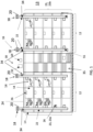
- FIG. 1 schematically represents a building 10 comprising several interior spaces 12.
- the interior spaces 12 can be entirely isolated from each other, it can for example be several separate occupation spaces.
- the building 10 comprises for example several dwellings, and/or spaces for human activity (offices, stores, classroom, workshops, etc.). Where applicable, building 10 is a building with mixed occupancy, comprising several types of occupancy spaces taken from the list above.
- an interior space 12 comprises several interior sub-spaces 14 which are only partially isolated from each other. It may for example be different rooms of a dwelling.
- the interior spaces 12 can be vertically superimposed on each other on several floors as illustrated in figure 1 . If the interior spaces 12 are dwellings, they can include wet rooms, namely kitchen, toilet and bathroom, each forming an interior sub-space 14 of the same interior space 12. For reasons of simplification of representation, the kitchens and bathrooms of different interior spaces 12 superimposed, are themselves superimposed. However, it could be otherwise.
- the building 10 comprises a ventilation installation 16 which extracts the stale air from the interior spaces 12 to the exterior 13 of the building 10.
- the ventilation installation 16 presented here is independent of the heating/air conditioning installations possibly fitted to the building 10 or some of its interior spaces 12.
- the ventilation installation 16 comprises a plurality of ventilation units 18.
- Each ventilation unit 18 comprises an air extraction assistance system 20 and one or more associated ducts 22 .
- Each air extraction assistance system 20 comprises an air extraction member 19 and an associated motor 21.
- the air extraction assistance system 20 allows natural and hybrid ventilation, that is to say having a part natural, and an assisted part when the temperature and/or the wind speed is below or below a certain value.
- the air extraction member 19 is for example for the case of a dynamic extraction, a fan rotated by a motor, the fan extracting the stale air from one or more associated ducts 22, like the system DYN ASTATO ® mentioned above.
- the air extraction member 19 could also be static extractors, associated with a fan operated by a motor and connected to one or more ducts 22, such as the NAVAIR ® system mentioned above.
- FIG 1 shows, for example, four ventilation units 18, with the four associated ducts 22 extending substantially vertically between the lowest interior space 12 (ground floor or even basement) served and the roof 24 of the building 12.
- the ducts 22 open into multiple rooftop locations 24.
- the ventilation installation 16 is, in one embodiment, an air induction system, by which a flow of air to be extracted in the duct is assisted by a flow of assistance air generated in each duct served .
- the air extraction member 19 is adapted to generate in each duct an upward flow of air.
- the ventilation installation 16 is therefore in one embodiment a hybrid system, which can alternatively take a natural operating mode (air extraction member 19 stopped) or a mechanically assisted operating mode (air extraction member air 19 on).
- the ventilation installation 16 has only a natural mode of operation or only a mechanically assisted mode of operation.
- the air extraction is done by suction or blowing air.
- Each duct 22 can serve several interior spaces 12, in particular several superimposed interior spaces to extract the stale air to the outside.
- the same interior space 12 can be served by several ducts, such as by two ducts, one of the ducts of which serves the two bathrooms, superimposed, of the two superimposed apartments.
- One or more ventilation accessories 26 serve as an interface between the interior space 12 and the duct 22 in question.
- the ventilation accessory or accessories 26 include, for example, extraction vents, air inlets, or air blowing system.
- the ventilation accessory(ies) 26 could possibly be adjustable to adapt the passage of air between the interior space 12 and the duct 22. A way of adjusting an extraction vent will be described below.
- Gas combustion appliances could also be connected to the ducts 22.
- An extractor could be provided at the end of each duct 22. According to one example, a static extractor is used, i.e. without mechanical assistance, by which the natural flow of air at the level of the extractor generates an air flow in the duct 22 by venturi effect.
- the ventilation installation 16 can also comprise air inlets, for example, in the form of an air vent (not shown), which could be located at the level of the dry rooms (eg bedrooms, living rooms, offices) .
- air inlets could optionally be adjustable to adapt the air passage cross-section between the exterior 13 and the interior space 12.
- the air inlets could also be controlled by the pollutant acquisition unit parallel to the one or more ventilation accessories.
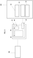
- FIG. 2 schematically represents a management system 30 of the ventilation installation 16.
- a group 23 of interior spaces 12 is, in one embodiment, all of the interior spaces served by the same ventilation unit 18.
- On the figure 1 there are for example two groups 23a, 23b of interior spaces 12.
- the management system 30 comprises a global management unit 32 which controls the ventilation units 18 according to parameters external to the building 10 and/or local parameters of the building 10 originating from a plurality of local data centralization units 34
- the plurality of local data centralization units 34 send, among other things, parameters related to the presence of pollutants in the interior spaces to the global management module 32.
- the management system 30 could also have a memory which would store parameters relating to the air extraction unit 19. For example, a first parameter could be linked to the fact that the ventilation installation 16 is an installation with air induction. This example could be refined by specifying other particularities of the ventilation installation 16, such as the version, or other.
- the management system 30 can be connected to the ventilation units 18 in a wired or wireless way, and in a direct or indirect way (for example through a network of connected objects of the SIGFOX, LoRa or equivalent type).
- the management system 30 may have the global management unit 32 disposed on the roof 24 as illustrated in figure 1 , or in a technical room of the building 10, if it is electrically connected to the ventilation units 18.
- the management system 30 could control several ventilation installations of neighboring buildings of the same set of buildings.
- the management system 30 could issue the same instruction to the air extraction units 19 associated with the different buildings, or different instructions, because certain parameters, such as the hours of enhanced assistance, or the speed wind, could differ according to the buildings (different heights, different locations, different types of occupation, ).
- the global management unit 32 comprises a communication module 36 adapted to receive a plurality of data, a calculation module 38 adapted to determine at least one global parameter from the plurality of data received by the communication module 36, and a control module 40 adapted to operate the ventilation unit 18 from said at least one parameter determined by the calculation module 38.
- the plurality of data received by the communication module 36 includes data external to the building 10 and data and/or parameters originating from the local data centralization units 34.
- the data external to the building 10 include for example an environmental climatic parameter.
- the value of the environmental climatic parameter can for example be provided by a local sensor (not shown) connected to the management system 30.
- a local sensor not shown
- the environmental climatic parameter could be provided by information technologies from a remote server or via the computing cloud (i.e. cloud) communicating with the management system 30. This could be in particular the case of the temperature and/or the humidity level at the level of the building 10.
- a remote server is a server which is not located in the building 10. The remote server can communicate with the management system 30 by wire or not. An example of a remote server will be given below (remote monitoring system 60).
- the communication module 36 can transmit to the remote server information relating to the ventilation unit 18 controlled by the management system 30, in particular an alert relating to a malfunction of the ventilation installation 16 and/or information allowing the remote server to check the correct operation of the ventilation installation 16.
- Other parameters can be sent to the remote server, in particular one or more of the parameters received by the communication module 36.
- the management system 30 may comprise a clock, and/or may receive information relating to the time from the remote server.
- the time information can be taken into account to increase the ventilation at times when probable occupancy of the building 10 can predict the need for greater ventilation.
- it may for example be meal times and/or bath times.
- the calculation module 38 can then, for example, in the pre-programmed time slots, increase the operating setpoint by one level, when possible.
- the calculation module 38 is adapted to determine from one or more of the parameters or data received by the communication module 36 an overall operating parameter of the management system 30, for example the operating speed of the ventilation units 18.
- the overall operating parameter(s) of the ventilation unit 18 can be determined by comparing the parameters and/or data received by the communication module 36 with predetermined operating set point values.
- the global management unit 32 could include a memory storing the values of several parameters and one or more predetermined rules for comparing and determining operating parameters.
- the predetermined rules could for example be applicable to only predetermined types of ventilation installation.
- the operating setpoint parameter(s) can be an absolute parameter, such as a parameter whose value is directly representative of the power or the ventilation speed of the air extraction member 19. It can also be a relative parameter, such as a parameter whose value indicates an increase or a decrease in the power or the current ventilation speed of the air extraction unit 19. It can be a boolean, a a real, a function, etc.
- the calculation module 38 is adapted to carry out a pre-processing of the values relating to the environmental climatic parameter. This could in particular be the case for the wind speed value, to take into account the frequent gusts or turbulence in this type of space.
- the global management unit 32 is an automaton.
- the calculation module 38 of the global management unit 32 includes an algorithm that self-regulates the speed of the air extraction member 19 of the ventilation unit 18 continuously according to predetermined values.
- the calculation module 38 can determine an operating setpoint parameter of the air extraction unit 19 (speed of rotation of a fan turbine, operating power, generated air flow, .. .) among five values from outdoor temperature and wind speed data according to the following table (T1 ⁇ T2 ⁇ T3 ⁇ T4 ⁇ T5 ⁇ T6, 0 ⁇ v1 ⁇ v2 ⁇ v4 ⁇ v4, 0 ⁇ K1 ⁇ K2 ⁇ K3 ⁇ K4): Temperature: Wind [T1; T2[ [T2; T3[ [T3; T4[ [T4; T5[ [T5; T6[ [0; v1[ 0 K2 K3 K4 0 [v1; v2[ 0 K1 K2 K3 0 [v2; v3[ 0 0 K1 K2 0 [v-3; v4[ 0 0 0 0 0 0 0 0 0 0 0 0 0 0 0 0 0 0 0 0 0 0 0 0
- the air extraction unit 19 can be stopped to avoid malfunctions.
- the higher the ambient temperature the greater the assistance required at the level of the air extraction member 19. from a predetermined temperature, where it can be assumed that ventilation can take place by opening the windows. Since the temperature is not the only determining parameter for the operation of the system, other parameters can influence it: the speed, the level of pollutants, the hygrometry, etc.
- the table above could be adapted. This determination can be made periodically, for example every minute.
- the air extraction members 19 can be subject to individualized or grouped instructions.
- the management system 30 can select a predetermined rule to be applied to a given air extraction member 19 or group of air extraction members 19 from among a plurality of predetermined rules.
- the control module 40 controls the air extraction assistance systems 20 (increases or decreases the speed of the motors 21 associated with the air extraction units 19) according to the operating parameters determined by the calculation module 38, as discussed above.
- the control module 40 can be connected to the air extraction units 19 in a wired or wireless way, and in a direct or indirect way (for example through a network of connected objects of the SIGFOX or LoRa type).
- the speed of the air extraction members 19 could be controlled continuously, variably or in stages.
- the local data centralization unit 34 groups the data associated with a group 23 of interior spaces 12 which are controlled by the same ventilation unit 18. This data can be processed before being sent to the global management unit 32 to adapt the ventilation accordingly.
- each local data centralization unit 34 is associated with a ventilation unit 18. In another embodiment, each local data centralization unit 34 is associated with several ventilation units 18.
- the local data centralization unit 34 includes a communication module 50, a calculation module 52, and optionally a control module 54 similar to those of the global management unit 32.
- the local data centralization unit 34 could also include a display constituting a man-machine interface and allowing the display of the collected data.
- the local data centralization unit 34 via its communication module 50, retrieves data relating to the levels of pollutants recorded in one or more interior spaces 12 and optionally, a parameter at the level of a group 23 d interior spaces 12 of the building 10. Other data or parameters can be received by the local data centralization unit 34.
- an air quality detection module 42 is in communication with the communication module 50 of the local data centralization unit 34.
- the air quality detection module 42 may be in the form of an indoor pollutant acquisition box placed in several of the indoor spaces 12 to record the levels of pollutants in the indoor spaces 12.
- the air quality detection module 42 comprises various sensors 44, for example sensors of gaseous atmospheric components such as formaldehyde (CH 2 O), carbon monoxide (CO), benzene (C 6 H 6 ), or indoor humidity sensors or human presence detectors.
- sensors 44 for example sensors of gaseous atmospheric components such as formaldehyde (CH 2 O), carbon monoxide (CO), benzene (C 6 H 6 ), or indoor humidity sensors or human presence detectors.
- This air quality detection module 42 recovers and processes the information from the sensors 44 using a microcontroller 46 integrated into the case on an electronic card 48.
- the microcontroller 46 processes this information according to the threshold values of the concentration of pollutants referenced in the internal memory of the latter.
- the microcontroller 46 sends the processed data to the communication module 50 of the local data centralization unit 34, which itself will transmit them after processing (example: average) or not, to the global management 32, thanks to the transmitter 49.
- the microcontroller 46 sends information corresponding to modulation commands of the ventilation accessory or accessories 26, for example opening and closing of the ( or the) extraction vents (eg variation of an opening section of the extraction mouth) of the interior space 12 associated.
- This command can be made directly by the indoor pollutant acquisition box 42 or else by the local data centralization unit 34 by sending the information from the indoor pollutant acquisition box 42 to the local data centralization unit.
- local data 34 to control the extraction outlet(s) by the control module 54 of the local data centralization unit 34.
- the pollutants will, for example, each have maximum admissible thresholds. If exceeded, a first opening of the extraction vents will allow greater extraction locally at housing level. Then, if this insufficiency is noted, more generally, on all the groups of dwellings associated with the same control unit, then a direct order to modulate the speeds of the ventilation system can be given.
- the communication unit 50 can receive a parameter at the level of a group 23 of interior spaces 12 of the building 10.
- This parameter can be a depression generated for the extraction of the stale air in, for example, the shaft of stairs common to a group 23 of interior spaces 12 stacked vertically on top of each other.
- These measurements can make it possible to determine whether these negative pressures generated are sufficient or too great to ensure optimum air quality and to avoid energy losses as much as possible. For this, it is possible to use the data collected in a single stairwell, and distribute this data to all the ventilation units 18. This could be the case if it is considered that the stairwell measured is representative of the others. stairwells of building 10 (control cage).
- one or more differential pressure sensors 55 would be positioned at relevant positions inside the ventilation and/or smoke ducts, connected to the stairwell.
- the data from the pressure sensors can be sent directly to the local data centralization unit 34 for relaying to the global management unit 32.
- the global management unit 32 could directly process the data from differential pressure sensors.
- the calculation module 52 of the local data centralization unit 34 calculates the average of the data received by type of pollutants, some of which are identified as priorities, on a group 23 of several interior spaces 12 controlled by a same ventilation unit 18. These averages will make it possible to determine whether the extraction of stale air is sufficient at the level of the group 23 of interior spaces 12 according to the limit thresholds deemed admissible which will be configured in the calculation module 52.
- the module calculation 52 is for example a microcontroller.
- the local data centralization unit 34 is capable of issuing control commands to the global management unit 32 which will pass them on to all the ventilation units 18.
- This communication between the local data centralization units 34 and the global management unit 32 can be done by wire or wireless, and directly or indirectly (for example through a network of connected objects such as SIGFOX or LoRa).
- control commands will have the effect of increasing or reducing the general extraction of stale air at the level of the ventilation system 16 according to the average levels of pollutants of the interior spaces 12 served.
- This information can be consulted by the asset managers who operate the ventilation system 16 via a portable or integrated Human/Machine interface (for example a control screen) and/or via the remote supervision system for the ventilation installations 16 described below. -below.
- Ventilation accessories e.g. controlled extract valve
- One or more ventilation accessories 26 of the interior spaces 12 can be modulated according to the data received by the indoor pollutant acquisition unit 42.
- the extraction vents of the interior spaces 12 can be provided with a system of automated opening and closing control according to the data received by the indoor pollutant acquisition box 42.
- This controlled extraction vent is then provided with an electronic data reception card either by wire or by wireless. These data can be acquired directly or indirectly (for example through a network of connected objects such as SIGFOX or LoRa).
- the electronic card Upon receipt of this data, the electronic card is capable of controlling an actuator allowing the opening and closing of the controlled extraction vent.
- the ventilation accessories 26, such as the controlled extraction vent thus constitute an actor in the modulation of flow at the level of the interior space 12 according to the levels of pollutants recorded by the acquisition unit of the interior pollutants.
- a possible coupling with controlled air inlets in dry rooms (living rooms, bedrooms, offices, etc.) can also be considered.
- control module 54 of the local data centralization unit 34 directly controls the size of the opening section of the extraction vents 26 according to the parameters determined by the calculation module 52.
- an additional sensor can be integrated directly into the mouth to take into account a dominant parameter of the room (e.g. hygrometry for the room bathroom, presence sensor for the toilet). This additional parameter may predominate over those sent by the pollutant acquisition unit.
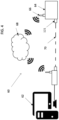
- the management system 30 may further comprise a remote supervision system 60. Thanks to this remote control system 60, at least part of the information on the operation of the ventilation installations 16, deemed useful to the assessment of air renewal in the dwellings, can be viewed on a computer interface such as a web platform 62 in near real time.
- a transmitter beacon 64 connecting to the global management unit 32 records the information, either previously configured via a Modbus link or any other technology wired equivalent or wireless for detailed information, or only via dry contacts for a simple overview of the operating status.
- This transmitter beacon 64 makes it possible to send this information to remote servers (for example via a computer cloud, commonly called a “cloud” 68) via transmitter 66 , either via a wired Ethernet network 70 (in dotted lines), or via the wireless network
- the means of remote data communication, proximal is a WI-FI or GSM or GPRS or SIGFOX or LoRaWAN network.
- the remote communication means provides access to the data of the device that is simple to implement and without geographical limitation.
- the web platform 62 could retrieve this information from the remote servers and translate it so that it can be interpreted by the operators coming to consult the platform.
- the information on this platform may be consulted in a distributed manner between the contracting authority or manager and also the operator.
- the occupant could also have access to the information associated with his accommodation, either via a web platform, or through his smartphone or any other equivalent means, to, for example, modulate the ventilation accessory(ies) himself, for example change the opening sections of the extraction vents 26 of its housing by acting between a minimum and a maximum of the levels of pollutants analyzed.
- the present invention may be of particular interest in the field of collective housing (or tertiary) ventilation. Indeed, it makes it possible to modulate the ventilation of different rooms associated with a common fan.
- the common fan can be, if necessary, set or adjustable to define a general ventilation strategy for the housings associated with it, on criteria, for example climatic, and intended for example to optimize the energy consumption of the common fan.
- the adjustable ventilation accessories make it possible to modulate this general strategy at the level of each dwelling to take into account the specificities of each dwelling, thus making it possible to optimize the energy savings made on the air flows extracted in relation to the needs of the rates. concentration of pollutants at the time to ensure good indoor air quality. Indeed, different housings associated with the same fan can meet different ventilation needs at any given time.
Landscapes
- Engineering & Computer Science (AREA)
- Chemical & Material Sciences (AREA)
- Combustion & Propulsion (AREA)
- Mechanical Engineering (AREA)
- General Engineering & Computer Science (AREA)
- Human Computer Interaction (AREA)
- Physics & Mathematics (AREA)
- Fluid Mechanics (AREA)
- Ventilation (AREA)
- Air Conditioning Control Device (AREA)
Claims (12)
- System (30) zum Management von Lüftungseinheiten (18) in einem Gebäude (10), umfassend mehrere Gruppen (23) von Innenräumen (12) und Lüftungseinheiten, wobei jede Gruppe von Innenräumen eine zugeordnete Lüftungseinheit aufweist, die verbrauchte Luft aus den Innenräumen (12) abzieht, wobei die Lüftungseinheit ein Luftabzugsunterstützungssystem (20) umfasst, wobei das Managementsystem eine globale Managementeinheit (32) und eine Mehrzahl von Einheiten zur Zentralisierung der lokalen Daten (34) umfasst, wobei die globale Managementeinheit (32) dazu ausgebildet ist, mit der Mehrzahl von Einheiten zur Zentralisierung der lokalen Daten (34) zu kommunizieren, um die Lüftungseinheiten zu steuern, wobei jede Einheit zur Zentralisierung der lokalen Daten wenigstens einer Lüftungseinheit zugeordnet ist,- wobei die globale Managementeinheit (32) des Gebäudes umfasst:∘ ein Kommunikationsmodul (36), das dazu ausgebildet ist, eine Mehrzahl von Daten zu empfangen, wobei die Mehrzahl von Daten Daten außerhalb des Gebäudes und wenigstens einen lokalen Parameter für den Betrieb einer jeden Lüftungseinheit umfasst,∘ ein Rechenmodul (38), das dazu ausgebildet ist, wenigstens einen globalen Betriebsparameter der Lüftungseinheiten aus der Mehrzahl von Daten zu bestimmen, die von dem Kommunikationsmodul (36) der globalen Managementeinheit (32) empfangen werden; und∘ ein Steuerungsmodul (40), das dazu ausgebildet ist, die Lüftungseinheiten auf der Grundlage des wenigstens einen globalen Betriebsparameters zu betreiben, der von dem Rechenmodul bestimmt wurde; und- wobei jede der Einheiten zur Zentralisierung der lokalen Daten (34) umfasst:dadurch gekennzeichnet,o ein Kommunikationsmodul (50), das dazu ausgebildet ist, Daten zu empfangen, die der Konzentration wenigstens eines Schadstoffs in wenigstens einem der Innenräume zugeordnet ist; undo ein Rechenmodul (52), das dazu ausgebildet ist, den lokalen Betriebsparameter aus den Daten zu bestimmen, die der Gruppe von Innenräumen zugeordnet sind und vom Kommunikationsmodul (50) empfangen werden,
dass das Rechenmodul (52) jeder Einheit zur Zentralisierung der lokalen Daten (34) dazu geeignet ist, den Mittelwert der Daten zu bilden, die pro Schadstofftyp über wenigstens eine der Gruppen (23) empfangen werden, die von derselben Lüftungseinheit (18) gesteuert werden, wobei eine der Einheiten zur Zentralisierung der lokalen Daten (34) dazu geeignet ist, Steuerbefehle an die globale Managementeinheit (32) auszugeben, auf der Basis der berechneten Schadstoffmittelwerte und von als zulässig erachteten Grenzwerten, die dazu geeignet sind, in dem Rechenmodul (52) parametrisiert zu werden. - Managementsystem nach Anspruch 1, wobei das Kommunikationsmodul (50), das in jeder der Einheiten zur Zentralisierung der lokalen Daten (34) enthalten ist, dazu ausgebildet ist, Daten zu empfangen, die der Konzentration wenigstens eines Schadstoffs wenigstens eines Luftqualitäts-Erfassungsmoduls (42) verbunden sind, wobei das wenigstens eine Erfassungsmodul wenigstens einem der Innenräume zugeordnet ist, um die Konzentration wenigstens eines Schadstoffs in dem wenigstens einen der Innenräume zu analysieren.
- Managementsystem nach Anspruch 2, wobeio jeder Innenraum wenigstens ein Lüftungszubehör (26) umfasst, das in Fluidverbindung mit der Lüftungseinheit seiner Gruppe von Innenräumen steht, wobei das wenigstens eine Lüftungszubehör mit dem wenigstens einen Luftqualitäts-Erfassungsmodul verbunden ist,o jedes der Luftqualitäts-Erfassungsmodule umfasst: einen Mikrocontroller (46), der dazu ausgebildet ist, einen Betriebsparameter des wenigstens einen Lüftungszubehörs auf der Basis der erfassten Konzentrationen wenigstens eines Schadstoffs zu bestimmen, wobei der Mikrocontroller dazu ausgebildet ist, das wenigstens eine Lüftungszubehör auf der Basis des Betriebsparameters des wenigstens einen Lüftungszubehörs zu betreiben.
- Managementsystem nach einem der Ansprüche 1 bis 3, wobei jede Einheit zur Zentralisierung der lokalen Daten einer eigenen Lüftungseinheit zugeordnet ist.
- Managementsystem nach einem der Ansprüche 1 bis 4, wobei die Daten außerhalb des Gebäudes wenigstens eines der folgenden Elemente umfassen: eine Temperatur der Außenluft, eine Geschwindigkeit der Außenluft, eine Zeitangabe.
- Managementsystem nach einem der Ansprüche 1 bis 5, wobei das Luftabzugsunterstützungssystem (20) ein Luftabzugselement (19) und einen zugeordneten Motor (21) umfasst und der globale Betriebsparameter eine Motorgeschwindigkeit ist.
- Managementsystem nach Anspruch 6, wobei das Rechenmodul der globalen Managementeinheit einen Algorithmus aufweist, der die Drehzahl des dem Luftabzugselement zugeordneten Motors kontinuierlich auf der Basis von vorbestimmten Werten selbst reguliert.
- Managementsystem nach einem der Ansprüche 1 bis 7, wobei wenigstens eine der Lüftungseinheiten wenigstens einen Differenzdrucksensor in einem Kanal aufweist, der mit der wenigstens einen Lüftungseinheit verbunden ist, und
das Kommunikationsmodul der Einheit zur Zentralisierung der lokalen Daten dazu ausgebildet ist, Druckinformationen über die mit den Kanälen verbundenen Innenräume zu empfangen, wobei die Druckinformationen von den Differenzdrucksensoren stammen. - Managementsystem nach einem der Ansprüche 1 bis 8, wobei das Kommunikationsmodul der globalen Managementeinheit dazu ausgebildet ist, mit einem entfernten Server des Gebäudes zu kommunizieren.
- Managementsystem nach einem der Ansprüche 1 bis 9, wobei die globale Managementeinheit dazu ausgebildet ist, auf einem Dach des Gebäudes angeordnet zu werden, und/oder die Einheit zur Zentralisierung der lokalen Daten dazu ausgebildet ist, in einem gemeinsamen Teil angeordnet zu werden, der die Innenräume einer gleichen Gruppe verbindet.
- Verfahren zum Management von Lüftungseinheiten (18) in einem Gebäude (10), umfassend mehrere Gruppen (23) von Innenräumen (12), wobei jede Gruppe von Innenräumen eine zugeordnete Lüftungseinheit (18) aufweist, die verbrauchte Luft aus den Innenräumen (12) abzieht, wobei jede Lüftungseinheit ein Luftabzugunterstützungssystem (20) aufweist, wobei das Managementsystem eine globale Managementeinheit (32) umfasst, die dazu ausgebildet ist, mit einer Mehrzahl von Einheiten zur Zentralisierung der lokalen Daten (34) zur Steuerung der Lüftungseinheiten zu kommunizieren, wobei das Verfahren Folgendes umfasst:o Empfangen von Daten, die mit Luftqualitätsinformationen von wenigstens einem Luftqualitäts-Erfassungsmodul verbunden sind, das wenigstens einem der Innenräume zugeordnet ist, durch ein Kommunikationsmodul (50) jeder Einheit zur Zentralisierung der lokalen Daten, wobei das wenigstens eine Erfassungsmodul dazu geeignet ist, die Konzentration wenigstens eines Schadstoffs in dem wenigstens einen der Innenräume zu analysieren;o Bestimmen von wenigstens einem lokalen Betriebsparameter einer Lüftungseinheit durch ein Rechenmodul (52) jeder Einheit zur Zentralisierung der lokalen Daten anhand der mit der Gruppe von Innenräumen verbundenen Daten, die von dem Kommunikationsmodul (50) empfangen werden;o Bilden des Durchschnitts der empfangenen Daten durch das Rechenmodul (52) nach Art der Schadstoffe in wenigstens einer der Gruppen (23), die von derselben Lüftungseinheit (18) gesteuert werden, wobei eine der Einheiten zur Zentralisierung der lokalen Daten (34) in der Lage ist, Steuerbefehle an die globale Managementeinheit (32) zu senden, auf der Basis der berechneten Durchschnittswerte der Schadstoffe und von als zulässig erachteten Grenzwerten, die in dem Rechenmodul (52) parametriert werden können;o Senden des wenigstens einen, lokalen Parameters für den Betrieb einer Lüftungseinheit durch das Kommunikationsmodul (50) jeder Einheit zur Zentralisierung der lokalen Daten an die globale Managementeinheit;o Empfangen einer Mehrzahl von Daten durch ein Kommunikationsmodul (36) der globalen Managementeinheit (32), um sie an ein Rechenmodul der globalen Managementeinheit (32) zu übermitteln, wobei die Mehrzahl von Daten Daten außerhalb des Gebäudes und den wenigstens einen lokalen Betriebsparameter einer Lüftungseinheit der Einheit zur Zentralisierung der lokalen Daten aufweist;o Bestimmen durch ein Rechenmodul (38) der globalen Managementeinheit (32) wenigstens eines globalen Betriebsparameters der Lüftungseinheiten aus der Mehrzahl von Daten, die von dem Kommunikationsmodul empfangen werden; undo Betreiben der Lüftungseinheiten durch ein Steuerungsmodul (40) der globalen Managementeinheit (32) anhand des wenigstens einen, globalen Parameters, der durch das Rechenmodul der globalen Managementeinheit (32) bestimmt wurde.
- Verfahren zur Steuerung der Lüftungsluft nach Anspruch 11, ferner umfassend:∘ Bestimmen eines Betriebsparameters für wenigstens ein Lüftungszubehör durch das Rechenmodul (52) jeder Einheit zur Zentralisierung der lokalen Daten auf der Grundlage von Daten, die der Gruppe von Innenräumen zugeordnet sind und vom Kommunikationsmodul jeder Einheit zur Zentralisierung der lokalen Daten empfangen werden, wobei jeder Innenraum wenigstens ein Lüftungszubehör (26) aufweist, das in Fluidverbindung mit der Lüftungseinheit seiner Gruppe steht, wobei das wenigstens eine Lüftungszubehör mit dem wenigstens einen Luftqualitäts-Erfassungsmodul verbunden ist; undo Betreiben des wenigstens einen Lüftungszubehörs durch das Luftqualitäts-Erfassungsmodul auf der Basis des Betriebsparameters des wenigstens einen Lüftungsgeräts, der durch das Luftqualitäts-Erfassungsmodul bestimmt wird.
Applications Claiming Priority (1)
| Application Number | Priority Date | Filing Date | Title |
|---|---|---|---|
| FR1760060A FR3072764B1 (fr) | 2017-10-24 | 2017-10-24 | Systeme de gestion d'unites de ventilation |
Publications (3)
| Publication Number | Publication Date |
|---|---|
| EP3477215A1 EP3477215A1 (de) | 2019-05-01 |
| EP3477215C0 EP3477215C0 (de) | 2023-07-12 |
| EP3477215B1 true EP3477215B1 (de) | 2023-07-12 |
Family
ID=60515685
Family Applications (1)
| Application Number | Title | Priority Date | Filing Date |
|---|---|---|---|
| EP18201935.6A Active EP3477215B1 (de) | 2017-10-24 | 2018-10-23 | Steuerungssystem von belüftungseinheiten |
Country Status (2)
| Country | Link |
|---|---|
| EP (1) | EP3477215B1 (de) |
| FR (1) | FR3072764B1 (de) |
Families Citing this family (5)
| Publication number | Priority date | Publication date | Assignee | Title |
|---|---|---|---|---|
| CN110469916A (zh) * | 2019-08-13 | 2019-11-19 | 青岛海尔空调器有限总公司 | 一种空调系统控制方法及空调系统 |
| CN110441484A (zh) * | 2019-09-23 | 2019-11-12 | 深圳市无眼界科技有限公司 | 一种空气气态污染物的检测装置及检测系统 |
| CN111238002B (zh) * | 2020-03-04 | 2021-08-10 | 青岛海信电子设备股份有限公司 | 一种列间空调风机转速控制方法 |
| FR3129460B1 (fr) * | 2021-11-22 | 2024-02-02 | Commissariat Energie Atomique | Installation de protection vis-à-vis de polluants présents dans l’air au sein d’un bâtiment industriel |
| CN114291245A (zh) * | 2022-01-05 | 2022-04-08 | 江南造船(集团)有限责任公司 | 一种船用卫生处所排风系统 |
Citations (1)
| Publication number | Priority date | Publication date | Assignee | Title |
|---|---|---|---|---|
| WO2013107461A1 (en) * | 2012-01-18 | 2013-07-25 | Vkr Holding A/S | Method and system for controlling ventilation in a building |
Family Cites Families (7)
| Publication number | Priority date | Publication date | Assignee | Title |
|---|---|---|---|---|
| FR2626324B1 (fr) | 1988-01-25 | 1993-04-09 | Paziaud Jacques | Procede de mise en mouvement de l'air dans une gaine d'aeration par jets d'air induits et son extension pour d'autres fluides |
| FR2740862B1 (fr) | 1995-11-03 | 1998-01-23 | Amphoux Andre | Dispositif pour aspirer un fluide gazeux a travers un conduit pour le rejeter a l'exterieur de celui-ci |
| FR2781278B1 (fr) | 1998-07-17 | 2000-09-29 | Andre Amphoux | Dispositif mixte, statique/dynamique pour l'evacuation de fluides gazeux |
| JP2001241738A (ja) * | 2000-03-02 | 2001-09-07 | Sanyo Electric Co Ltd | 冷凍空調装置及びその制御方法 |
| FR2851641B1 (fr) | 2003-02-26 | 2017-08-18 | Astato | Procede de reglage d'un ventilateur d'un systeme de ventilation d'un batiment |
| FR3030697B1 (fr) * | 2014-12-23 | 2019-11-08 | Andre Amphoux | Systeme de controle d'installations de ventilation, installation de ventilation comprenant un tel systeme de controle, et gamme |
| JP6497195B2 (ja) * | 2015-04-28 | 2019-04-10 | ダイキン工業株式会社 | 空調装置 |
-
2017
- 2017-10-24 FR FR1760060A patent/FR3072764B1/fr active Active
-
2018
- 2018-10-23 EP EP18201935.6A patent/EP3477215B1/de active Active
Patent Citations (1)
| Publication number | Priority date | Publication date | Assignee | Title |
|---|---|---|---|---|
| WO2013107461A1 (en) * | 2012-01-18 | 2013-07-25 | Vkr Holding A/S | Method and system for controlling ventilation in a building |
Also Published As
| Publication number | Publication date |
|---|---|
| EP3477215C0 (de) | 2023-07-12 |
| EP3477215A1 (de) | 2019-05-01 |
| FR3072764A1 (fr) | 2019-04-26 |
| FR3072764B1 (fr) | 2020-09-04 |
Similar Documents
| Publication | Publication Date | Title |
|---|---|---|
| EP3477215B1 (de) | Steuerungssystem von belüftungseinheiten | |
| US11250679B2 (en) | Systems and methods for categorizing motion events | |
| EP3637694A1 (de) | Steuerung einer smart-home-vorrichtung mit mehreren quellen | |
| US8063775B2 (en) | Energy management system | |
| US20190141919A1 (en) | Irrigation management via intelligent image analysis | |
| US20110113120A1 (en) | Facility maintenance and management system | |
| US20130173062A1 (en) | Smart building unified managed solutions | |
| US10948215B2 (en) | System and method for wireless environmental zone control | |
| US20200049358A1 (en) | Adaptive ventilation system | |
| EP1301749A1 (de) | Verfahren und vorrichtung für die luftgeschwindigkeitsüberwachung insbesondere für einen laborabzugschrank | |
| EP2853823B1 (de) | Parametrierbares Belüftungssystem | |
| EP2891846A2 (de) | Steuerungsverfahren eines Belüftungssystems mit einfachem Luftfluss | |
| CN212204952U (zh) | 用于银行网点室内环境调节的系统 | |
| WO2016046389A1 (fr) | Système climatique connecté | |
| EP3237810B1 (de) | System zur steuerung einer belüftungsanlage, belüftungsanlage mit solch einem steuerungssystem und bereich | |
| EP2998657B1 (de) | Belüftungssystem eines gebäudes und steuerbares mittel zum unterteiltem lufteinlass | |
| WO2004076932A2 (fr) | Procede de reglage d’un ventilateur d’un systeme de ventilation d’un batiment | |
| FR2974404A1 (fr) | Systeme de ventilation | |
| FR3018901A1 (fr) | Systeme de climatisation naturelle a ventilation mecanique controlee | |
| FR3162075A1 (fr) | Système d'extracteur d'air stato-dynamique avec moteurs EC et capteurs Intégrés | |
| FR2967793A1 (fr) | Systeme de gestion de l'energie dans un batiment | |
| FR3061773A1 (fr) | Unite de detection et d'analyse, dispositif de controle de parametres physico-chimiques d'un environnement comprenant ladite unite, et procede de controle associe | |
| EP2442041A1 (de) | Mechanische Belüftungsinstallation durch feuchtigkeitsregulierte Belüftung, und zugehöriges Verfahren | |
| EP2853830B1 (de) | Belüftungssystemmodul und Gebäudebelüftungssystem, das über Internet ferngesteuert werden kann | |
| FR2935467A1 (fr) | Procede et installation de ventilation |
Legal Events
| Date | Code | Title | Description |
|---|---|---|---|
| PUAI | Public reference made under article 153(3) epc to a published international application that has entered the european phase |
Free format text: ORIGINAL CODE: 0009012 |
|
| STAA | Information on the status of an ep patent application or granted ep patent |
Free format text: STATUS: THE APPLICATION HAS BEEN PUBLISHED |
|
| AK | Designated contracting states |
Kind code of ref document: A1 Designated state(s): AL AT BE BG CH CY CZ DE DK EE ES FI FR GB GR HR HU IE IS IT LI LT LU LV MC MK MT NL NO PL PT RO RS SE SI SK SM TR |
|
| AX | Request for extension of the european patent |
Extension state: BA ME |
|
| STAA | Information on the status of an ep patent application or granted ep patent |
Free format text: STATUS: REQUEST FOR EXAMINATION WAS MADE |
|
| 17P | Request for examination filed |
Effective date: 20191030 |
|
| RBV | Designated contracting states (corrected) |
Designated state(s): AL AT BE BG CH CY CZ DE DK EE ES FI FR GB GR HR HU IE IS IT LI LT LU LV MC MK MT NL NO PL PT RO RS SE SI SK SM TR |
|
| STAA | Information on the status of an ep patent application or granted ep patent |
Free format text: STATUS: EXAMINATION IS IN PROGRESS |
|
| 17Q | First examination report despatched |
Effective date: 20210428 |
|
| GRAP | Despatch of communication of intention to grant a patent |
Free format text: ORIGINAL CODE: EPIDOSNIGR1 |
|
| STAA | Information on the status of an ep patent application or granted ep patent |
Free format text: STATUS: GRANT OF PATENT IS INTENDED |
|
| INTG | Intention to grant announced |
Effective date: 20230221 |
|
| GRAS | Grant fee paid |
Free format text: ORIGINAL CODE: EPIDOSNIGR3 |
|
| GRAA | (expected) grant |
Free format text: ORIGINAL CODE: 0009210 |
|
| STAA | Information on the status of an ep patent application or granted ep patent |
Free format text: STATUS: THE PATENT HAS BEEN GRANTED |
|
| AK | Designated contracting states |
Kind code of ref document: B1 Designated state(s): AL AT BE BG CH CY CZ DE DK EE ES FI FR GB GR HR HU IE IS IT LI LT LU LV MC MK MT NL NO PL PT RO RS SE SI SK SM TR |
|
| REG | Reference to a national code |
Ref country code: CH Ref legal event code: EP |
|
| REG | Reference to a national code |
Ref country code: DE Ref legal event code: R096 Ref document number: 602018053123 Country of ref document: DE |
|
| REG | Reference to a national code |
Ref country code: IE Ref legal event code: FG4D Free format text: LANGUAGE OF EP DOCUMENT: FRENCH |
|
| U01 | Request for unitary effect filed |
Effective date: 20230807 |
|
| U07 | Unitary effect registered |
Designated state(s): AT BE BG DE DK EE FI FR IT LT LU LV MT NL PT SE SI Effective date: 20230811 |
|
| U20 | Renewal fee for the european patent with unitary effect paid |
Year of fee payment: 6 Effective date: 20230919 |
|
| REG | Reference to a national code |
Ref country code: LT Ref legal event code: MG9D |
|
| PG25 | Lapsed in a contracting state [announced via postgrant information from national office to epo] |
Ref country code: GR Free format text: LAPSE BECAUSE OF FAILURE TO SUBMIT A TRANSLATION OF THE DESCRIPTION OR TO PAY THE FEE WITHIN THE PRESCRIBED TIME-LIMIT Effective date: 20231013 |
|
| PG25 | Lapsed in a contracting state [announced via postgrant information from national office to epo] |
Ref country code: ES Free format text: LAPSE BECAUSE OF FAILURE TO SUBMIT A TRANSLATION OF THE DESCRIPTION OR TO PAY THE FEE WITHIN THE PRESCRIBED TIME-LIMIT Effective date: 20230712 |
|
| PG25 | Lapsed in a contracting state [announced via postgrant information from national office to epo] |
Ref country code: IS Free format text: LAPSE BECAUSE OF FAILURE TO SUBMIT A TRANSLATION OF THE DESCRIPTION OR TO PAY THE FEE WITHIN THE PRESCRIBED TIME-LIMIT Effective date: 20231112 |
|
| PG25 | Lapsed in a contracting state [announced via postgrant information from national office to epo] |
Ref country code: RS Free format text: LAPSE BECAUSE OF FAILURE TO SUBMIT A TRANSLATION OF THE DESCRIPTION OR TO PAY THE FEE WITHIN THE PRESCRIBED TIME-LIMIT Effective date: 20230712 Ref country code: NO Free format text: LAPSE BECAUSE OF FAILURE TO SUBMIT A TRANSLATION OF THE DESCRIPTION OR TO PAY THE FEE WITHIN THE PRESCRIBED TIME-LIMIT Effective date: 20231012 Ref country code: IS Free format text: LAPSE BECAUSE OF FAILURE TO SUBMIT A TRANSLATION OF THE DESCRIPTION OR TO PAY THE FEE WITHIN THE PRESCRIBED TIME-LIMIT Effective date: 20231112 Ref country code: HR Free format text: LAPSE BECAUSE OF FAILURE TO SUBMIT A TRANSLATION OF THE DESCRIPTION OR TO PAY THE FEE WITHIN THE PRESCRIBED TIME-LIMIT Effective date: 20230712 Ref country code: GR Free format text: LAPSE BECAUSE OF FAILURE TO SUBMIT A TRANSLATION OF THE DESCRIPTION OR TO PAY THE FEE WITHIN THE PRESCRIBED TIME-LIMIT Effective date: 20231013 Ref country code: ES Free format text: LAPSE BECAUSE OF FAILURE TO SUBMIT A TRANSLATION OF THE DESCRIPTION OR TO PAY THE FEE WITHIN THE PRESCRIBED TIME-LIMIT Effective date: 20230712 |
|
| PG25 | Lapsed in a contracting state [announced via postgrant information from national office to epo] |
Ref country code: PL Free format text: LAPSE BECAUSE OF FAILURE TO SUBMIT A TRANSLATION OF THE DESCRIPTION OR TO PAY THE FEE WITHIN THE PRESCRIBED TIME-LIMIT Effective date: 20230712 |
|
| REG | Reference to a national code |
Ref country code: DE Ref legal event code: R097 Ref document number: 602018053123 Country of ref document: DE |
|
| PG25 | Lapsed in a contracting state [announced via postgrant information from national office to epo] |
Ref country code: SM Free format text: LAPSE BECAUSE OF FAILURE TO SUBMIT A TRANSLATION OF THE DESCRIPTION OR TO PAY THE FEE WITHIN THE PRESCRIBED TIME-LIMIT Effective date: 20230712 Ref country code: RO Free format text: LAPSE BECAUSE OF FAILURE TO SUBMIT A TRANSLATION OF THE DESCRIPTION OR TO PAY THE FEE WITHIN THE PRESCRIBED TIME-LIMIT Effective date: 20230712 Ref country code: CZ Free format text: LAPSE BECAUSE OF FAILURE TO SUBMIT A TRANSLATION OF THE DESCRIPTION OR TO PAY THE FEE WITHIN THE PRESCRIBED TIME-LIMIT Effective date: 20230712 Ref country code: SK Free format text: LAPSE BECAUSE OF FAILURE TO SUBMIT A TRANSLATION OF THE DESCRIPTION OR TO PAY THE FEE WITHIN THE PRESCRIBED TIME-LIMIT Effective date: 20230712 |
|
| PLBE | No opposition filed within time limit |
Free format text: ORIGINAL CODE: 0009261 |
|
| STAA | Information on the status of an ep patent application or granted ep patent |
Free format text: STATUS: NO OPPOSITION FILED WITHIN TIME LIMIT |
|
| PG25 | Lapsed in a contracting state [announced via postgrant information from national office to epo] |
Ref country code: MC Free format text: LAPSE BECAUSE OF FAILURE TO SUBMIT A TRANSLATION OF THE DESCRIPTION OR TO PAY THE FEE WITHIN THE PRESCRIBED TIME-LIMIT Effective date: 20230712 |
|
| REG | Reference to a national code |
Ref country code: CH Ref legal event code: PL |
|
| 26N | No opposition filed |
Effective date: 20240415 |
|
| GBPC | Gb: european patent ceased through non-payment of renewal fee |
Effective date: 20231023 |
|
| PG25 | Lapsed in a contracting state [announced via postgrant information from national office to epo] |
Ref country code: GB Free format text: LAPSE BECAUSE OF NON-PAYMENT OF DUE FEES Effective date: 20231023 |
|
| PG25 | Lapsed in a contracting state [announced via postgrant information from national office to epo] |
Ref country code: CH Free format text: LAPSE BECAUSE OF NON-PAYMENT OF DUE FEES Effective date: 20231031 |
|
| PG25 | Lapsed in a contracting state [announced via postgrant information from national office to epo] |
Ref country code: GB Free format text: LAPSE BECAUSE OF NON-PAYMENT OF DUE FEES Effective date: 20231023 Ref country code: CH Free format text: LAPSE BECAUSE OF NON-PAYMENT OF DUE FEES Effective date: 20231031 |
|
| U20 | Renewal fee for the european patent with unitary effect paid |
Year of fee payment: 7 Effective date: 20240814 |
|
| PG25 | Lapsed in a contracting state [announced via postgrant information from national office to epo] |
Ref country code: IE Free format text: LAPSE BECAUSE OF NON-PAYMENT OF DUE FEES Effective date: 20231023 |
|
| PG25 | Lapsed in a contracting state [announced via postgrant information from national office to epo] |
Ref country code: IE Free format text: LAPSE BECAUSE OF NON-PAYMENT OF DUE FEES Effective date: 20231023 |
|
| PG25 | Lapsed in a contracting state [announced via postgrant information from national office to epo] |
Ref country code: CY Free format text: LAPSE BECAUSE OF FAILURE TO SUBMIT A TRANSLATION OF THE DESCRIPTION OR TO PAY THE FEE WITHIN THE PRESCRIBED TIME-LIMIT; INVALID AB INITIO Effective date: 20181023 |
|
| U1N | Appointed representative for the unitary patent procedure changed after the registration of the unitary effect |
Representative=s name: PLASSERAUD IP; FR |
|
| PG25 | Lapsed in a contracting state [announced via postgrant information from national office to epo] |
Ref country code: HU Free format text: LAPSE BECAUSE OF FAILURE TO SUBMIT A TRANSLATION OF THE DESCRIPTION OR TO PAY THE FEE WITHIN THE PRESCRIBED TIME-LIMIT; INVALID AB INITIO Effective date: 20181023 |
|
| U20 | Renewal fee for the european patent with unitary effect paid |
Year of fee payment: 8 Effective date: 20250814 |
|
| PG25 | Lapsed in a contracting state [announced via postgrant information from national office to epo] |
Ref country code: TR Free format text: LAPSE BECAUSE OF FAILURE TO SUBMIT A TRANSLATION OF THE DESCRIPTION OR TO PAY THE FEE WITHIN THE PRESCRIBED TIME-LIMIT Effective date: 20230712 |