EP3477216B1 - Unité de gestion de l'air - Google Patents
Unité de gestion de l'air Download PDFInfo
- Publication number
- EP3477216B1 EP3477216B1 EP17382723.9A EP17382723A EP3477216B1 EP 3477216 B1 EP3477216 B1 EP 3477216B1 EP 17382723 A EP17382723 A EP 17382723A EP 3477216 B1 EP3477216 B1 EP 3477216B1
- Authority
- EP
- European Patent Office
- Prior art keywords
- air handling
- air
- air filter
- handling unit
- profiles
- Prior art date
- Legal status (The legal status is an assumption and is not a legal conclusion. Google has not performed a legal analysis and makes no representation as to the accuracy of the status listed.)
- Active
Links
Images




Classifications
-
- F—MECHANICAL ENGINEERING; LIGHTING; HEATING; WEAPONS; BLASTING
- F24—HEATING; RANGES; VENTILATING
- F24F—AIR-CONDITIONING; AIR-HUMIDIFICATION; VENTILATION; USE OF AIR CURRENTS FOR SCREENING
- F24F13/00—Details common to, or for air-conditioning, air-humidification, ventilation or use of air currents for screening
- F24F13/28—Arrangement or mounting of filters
-
- F—MECHANICAL ENGINEERING; LIGHTING; HEATING; WEAPONS; BLASTING
- F24—HEATING; RANGES; VENTILATING
- F24F—AIR-CONDITIONING; AIR-HUMIDIFICATION; VENTILATION; USE OF AIR CURRENTS FOR SCREENING
- F24F2221/00—Details or features not otherwise provided for
- F24F2221/14—Details or features not otherwise provided for mounted on the ceiling
Definitions
- the present invention relates to the industry dedicated to air handling units, and more specifically to the industry dedicated to air handling units intended for being arranged in false ceilings.
- Air handling units i.e., machine units which handle airflow, in addition to being able also to produce or generate said airflow, are widely known today. Handling of said airflow entails the use of air filters to remove unwanted solid particles from the air. Additionally, handling of the air may or may not include heating or cooling said air, humidification or dehumidification, etc.
- said air filters Due to the removal of said particles, such as dust, pollen and bacteria, for example, said air filters must be replaced or at least cleaned every so often for the duration of use of the air handling units in order to prevent particle saturation such that not only will the filters stop performing their function, but they will also lead to a malfunction of the air handling units, where they can even result in the air handling units breaking down.
- Arranging air handling units in places hidden from view is also known. It is therefore common for these units to be located in spaces corresponding to false ceilings. The arrangement of said units therefore does not have any undesired visual impact in the rooms in which they are arranged.
- the present invention provides an air handling unit (AHU) providing flexibility for placing and removing air filters as it makes access to the air filter possible through portions that are angled with respect to one another, for example, both through a side and through a lower portion.
- AHU air handling unit
- the air handling unit comprises a volumetric space for housing an air filter; in addition to a support, which comprises a structure for holding the air filter, which defines a rail along which the air filter can be moved between an inner portion and an outer portion of the structure according to a first direction; and guiding means in the volumetric space for the movement of the structure between an inner portion and an outer portion of the air handling unit according to a second direction.
- the air handling unit additionally comprises a first opening for the passage of the air filter between the inner portion and the outer portion of the air handling unit according to the first direction; and a second opening for the passage of the structure between the inner portion and the outer portion of the air handling unit according to the second direction.
- the first direction and the second direction are preferably angled forming an angle between 75° and 105° with respect to one another, and more preferably 90°.
- the support additionally comprises first fixing means configured for fixing the air filter in the structure by pressure.
- the first fixing means secure the fixing of the air filter in the structure.
- These first fixing means comprise a guide element and a slot that is misaligned with respect to the first direction, where the guide element and the slot are configured such that where the guide element is housed in the slot, a relative movement can be established therebetween.
- the support additionally comprises a first profile, where the slot is located in the first profile and the guide element is fixed in the structure.
- the first profiles are preferably two in number, where the first profiles are retained with respect to two faces of the structure which are parallel to one another.
- at least one of the first profiles has a tapering element attached thereto for tapering the rail along which the air filter can be moved.
- the rail can therefore be adapted to different air filter dimensions.
- the support additionally comprises second fixing means configured for fixing the structure in the volumetric space by pressure.
- the second fixing means secure the fixing of the structure in the volumetric space.
- These second fixing means comprise a guide part and a channel that is misaligned with respect to the second direction, where the guide part and the channel are configured such that where the guide part is housed in the channel, a relative movement can be established therebetween.
- the support additionally comprises a second profile, where the channel is located in the second profile and the guide part is fixed in the volumetric space.
- the second profiles are preferably two in number, where the second profiles are retained with respect to fixed portions of the air handling unit.
- the present invention relates to an air handling unit (AHU), i.e., a unit provided for handling at least one airflow.
- AHU air handling unit
- the air handling unit (AHU) can also be provided for producing or generating said airflow. Handling of said airflow entails air filtration for removing unwanted solid particles from the air. Additionally, handling of the air may or may not include heating or cooling said air, humidification or dehumidification, etc.
- the air handling unit comprises an outer shell for demarcating a compartment.
- Said shell is defined by sides, preferably six in number, and includes panels surrounding various components, such as at least one air filter (1), for example.
- the air handling unit comprises at least one volumetric space (2) defined in the compartment.
- Each of the volumetric spaces (2) is configured for housing one of the air filters (1).
- the air handling unit comprises a window (3) defined on one of the sides of the outer shell, specifically in correspondence with the volumetric space (2), for fluid communication between an inner portion and an outer portion of the air handling unit.
- the air handling unit can therefore comprise an air-driving element (4) to cause air to circulate through the air handling unit.
- the air handling unit comprises a first opening (5) for communication between the inner portion and the outer portion of the air handling unit.
- the first opening (5) is located in correspondence with the volumetric space (2) such that the air filter (1) can be introduced into and removed from the volumetric space (2) and the air handling unit through said opening.
- the first opening (5) is preferably located on another one of the sides of the outer shell other than that of the window (3).
- the air handling unit comprises a first cover (5') for covering or closing the first opening (5).
- the air handling unit comprises a second opening (6) for communication between the inner portion and the outer portion of the air handling unit itself.
- the second opening (6) is also located in correspondence with the volumetric space (2) such that the air filter (1) can be introduced into and removed from the volumetric space (2) and the air handling unit through said opening.
- the second opening (6) is preferably located on another additional side of the shell outer other than that of the window (3) and that of the first opening (5). More specifically, this another additional side of the outer shell is angled with respect to the side on which the first opening (5) is located, preferably forming 90° with respect to one another.
- the air handling unit comprises a second cover (6') for covering or closing the second opening (6).
- the air handling unit additionally comprises arms (6.1) articulated at their longitudinal ends for moving the second cover (6') between an open position and a closed position, where said cover is kept attached to the outer shell. Said second cover (6') is therefore prevented from being able to fall or come off unintentionally.
- the air handling unit additionally comprises a support (7) for arrangement of the air filter (1).
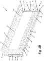
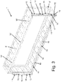
- the support (7) in turn comprises a structure (8) for holding the air filter (1) which has faces, preferably six in number, defining a rail along which the air filter (1) can be moved.
- the structure (8) comprises a detachable corner (8.1) to make the assembly thereof in the unit easier. Therefore, the volumetric space (2) is additionally configured for housing said structure (8).
- the air filter (1) is moved along the rail with respect to the structure (8) according to a first direction (A).
- the rail has an open end (8'), in correspondence with one of the faces of the structure (8) to allow the movement of the air filter (1) between an inner portion and an outer portion of the structure (8); in other words, one of the faces of the structure (8) is configured or established such that it allows the passage of the air filter (1) therethrough.
- the open end (8') of the rail is arranged facing or in correspondence with the first opening (5) such that the air filter (1) can be introduced into or removed from the volumetric space (2), and therefore the air handling unit, by means of the movement of the structure (8) along the rail according to the first direction (A) and through the first opening (5).
- the air handling unit provides a first path of movement for the air filter (1) through one the faces of the outer shell.
- the structure (8) can in turn be moved with respect to the volumetric space (2) according to a second direction (B).
- the support (7) comprises guiding means (9) which are located in correspondence with the volumetric space (2) to guide the structure (8), where the air filter (1) may be housed therein when said structure is moved according to said second direction (B) between the inner portion and the outer portion of the air handling unit.
- the first direction (A) and the second direction (B) are angled with respect to one another forming an angle preferably between 75° and 105°, and more preferably 90°.
- the guiding means (9) comprise fixed elements fixed in the inner portion of the air handling unit, preferably columns.
- the fixed elements are fixed to one of the sides of the outer shell at a first longitudinal end and to another one of the sides of the outer shell at a second longitudinal end, where said sides are preferably parallel to one another.
- the second opening (6) is sized such that the structure (8) can also be introduced and removed through same.
- the air handling unit therefore provides a second path of movement for the air filter (1) through another one of the faces of the outer shell other than the face through which the first access is provided.
- the air handling unit therefore provides access to the air filter (1), where the air filter (1) is located in the volumetric space (2) indistinctly through either the first opening (5) or through the second opening (6), where said openings (5, 6) are located according to planes that are angled with respect to one another, preferably between 75° and 105°, and more preferably 90°.
- the first opening (5) can be defined according to a vertical plane and the second cover (6) according to a horizontal plane, according to one of the lateral sides and the lower side of the outer shell, respectively.
- the movement of the air filter (1) along the rail according to the first direction (A) entails the air filter entering or exiting the volumetric space (2) according to the horizontal plane
- the movement of the structure (8) with respect to the volumetric space (2) according to the second direction (B) entails the structure entering or exiting the air handling unit according to the vertical plane, according to the lower and lateral sides, respectively.
- the support (7) comprises first fixing means configured for fixing the air filter (1) in the structure (8) by pressure. These first fixing means both fix the air filter (1) to and release it from the structure (8) in a quick and simple manner. Said fixing can be performed by means of pushing and said release can be performed by means of pulling.
- the first fixing means comprise at least one guide element (10) and a slot (11).
- the guide elements (10) and the slots (11) are preferably at least two in number, such that stability is provided in the relative movement between the slots (11) and the guide elements (10).
- the guide elements (10) have a head having a larger dimension than the slots (11), while at the same time an elongated body having smaller dimensions than said slots (11). Therefore, the guide elements (10) can be fixed by means of the bodies being inserted through the corresponding slot (11), where axial retention is established according to the longitudinal extension of the body by the contact of the slots (11) in the heads, while at the same time allowing movement of the guide elements (10) along the slots (11).
- the slots (11) in turn have a start point and an end point joined by an extension defined by a curve. Likewise, the start point and the end point are located such that an imaginary straight line (not shown in the drawings) for joining both points is misaligned, shifted or angled with respect to the first direction (A). Therefore, a combined relative movement according to a longitudinal movement according to the first direction (A) and a lateral movement according to a direction perpendicular to the first direction (A) are established therebetween by means of the guide elements (10) and the slots (11).
- the support (7) additionally comprises at least a first profile (12) to therefore provide the possibility of adapting the invention to conventional air filters (1), i.e., without having to add the guide elements (10) or slots (11) in conventional air filters (1).
- the slots (11) are located in the first profile (12) and the guide elements (10) are arranged such that they are fixed in the structure (8), exerting axial retention on the first profile (12) through the heads.
- the first fixing means can additionally comprise coupling elements (10') that can be fixed in correspondence with free ends of the elongated bodies.
- the slots (11) can be located in the structure (8) and the guide elements (10) can be fixed in the first profile (12).
- the first profile (12) having a longitudinal extension is arranged such that it is axially retained by means of the heads of the corresponding guide elements (10) with respect to one of the faces of the structure (8), the upper face, while it can be moved parallel to said face of the structure (8) at the same time.
- said first profile (12) can be moved according to the extension of the slots (11).
- the first profile (12) can thus be moved longitudinally according to the first direction (A) and laterally such that it is moved closer to and away from one of the faces of the structure (8), a larger face, which is perpendicular to the face where the corresponding guide elements (10) are fixed.
- said first profile (12) is additionally moved laterally towards said larger face of the structure (8) such that where the air filter (1) is housed in the structure (8), the air filter (1) is pressed against the larger face of the structure (8).
- the support (7) comprises a tapering element (12') attached to the first profile (12) such that they are moved together.
- the tapering element (12') presses the air filter (1) against said larger face of the structure (8).
- the tapering element (12') is used to enable using the structure (8) when the air filter (1) has smaller dimensions, or at least a smaller width, than the rail.
- the support (7) lacks the tapering element (12') such that the first profile (12) directly presses the air filter (1) against said larger face of the structure (8). This embodiment allows using the structure (8) when the air filter (1) has smaller dimensions, or at least a smaller width, than the rail.
- first profile (12) is moved according to another direction of movement opposite the preceding one, said first profile (12) is additionally moved laterally away from said larger face such that where the air filter (1) is housed in the structure (8), the air filter (1) is no longer subjected to the pressure retaining it on the rail, said pressure being exerted directly through either the first profile (12) or the tapering element (12').
- the first profiles (12) are two in number in order to exert greater pressure on a larger surface of the air filter (1), and therefore exert pressure in a more uniform and effective manner.
- the first profiles (12) are arranged such that they are retained against two of the faces of the structure (8), the upper face and the lower face, which are opposite one another, i.e., one is facing the other.
- said first profiles (12) can both be moved laterally according to the same direction of movement to exert pressure in the air filter (1) against the same face of the structure (8), i.e., against the larger face, and according to the same other direction of movement to stop exerting pressure against the larger face.
- the tapering elements (12') that can be used are preferably two in number, one for each of the first profiles (12).
- the support (7) comprises second fixing means configured for fixing the structure (8) in the volumetric space (2) by pressure.
- These second fixing means both fix and release the structure (8) with respect to the volumetric space (2) in a quick and simple manner. Said fixing can be performed by means of pushing and said release by means of pulling.
- the second fixing means comprise at least one guide part (13) and a channel (14).
- the guide parts (13) and the channels (14) are preferably at least two in number such that stability is provided in the relative movement between the guide parts (13) and the channels (14).
- the guide parts (13) are similar to the guide elements (10) and the channels (14) are similar to the slots (11).
- the guide parts (13) have a protuberance having a larger size than the channels (14), while at the same time an elongated section having smaller dimensions than said channels (14).
- the guide parts (13) can therefore be fixed by means of the sections being inserted through the corresponding channel (14), where another axial retention is established according to the longitudinal extension of the body by contact of the channels (14) in the protuberances, while at the same time allowing movement of the guide parts (13) along the channels (14).
- the channels (14) in turn have a beginning and an end joined by an extension defined by another curve. Likewise, the beginning and the end are located such that another imaginary straight line (not shown in the drawings) for joining both the beginning and the end is misaligned, shifted or angled with respect to the second direction (B). Therefore, a combined relative movement according to a longitudinal movement according to the second direction (B), and a lateral movement according to a direction perpendicular to the second direction (B), and preferably also perpendicular to the first direction (A), are established therebetween by means of the guide parts (13) and the channels (14).
- the support (7) additionally comprises at least a second profile (15) to therefore provide the possibility of adapting the invention to conventional air handling units.
- the channels (14) are located in the second profile (15) and the guide parts (13) are arranged such that they are fixed in fixed portions of the air handling unit, exerting the other axial retention on the second profiles (15) through the protuberances.
- These fixed portions may be the guiding means (9) and/or the panels of the shell.
- the channels (14) can be located in the fixed portions of the air handling unit and the guide parts (13) can be fixed in the second profiles (15).
- the second profile (15) having a longitudinal extension is arranged such that it is axially retained by means of the protuberances of the corresponding guide parts (13) with respect to one of said fixed portions of the air handling unit, while it can be moved parallel to said fixed portion at the same time.
- said second profile (15) can be moved according to the extension of the channels (14).
- the second profile (15) can thus be moved longitudinally according to the second direction (B) and laterally such that it is moved closer to and away from one of the faces of the structure (8), preferably the same larger face as for the case of the first profiles.
- said second profile (15) is moved according to one direction of movement, said second profile (15) is additionally moved laterally towards said larger face of the structure (8) such that where the structure (8) is in the volumetric space (2), the structure (8) is pressed by the second profile (15) against a fixed portion of the air handling unit, such as at least one of the columns of the support (7), for example.
- said second profile (15) is additionally moved laterally away from said larger face such that where the structure (8) is in the volumetric space (2), the pressure retaining the structure (8) in the volumetric space (2) is released.
- the second profiles (15) are preferably two in number in order to exert greater pressure on a larger surface of the structure (8), and to therefore exert pressure in a more uniform and effective manner.
- the second profiles (15) are arranged such that they are retained against fixed portions of the air handling unit.
- said second profiles (15) can both be moved laterally according to the same direction of movement to exert pressure in the air filter (1) against the same face of the structure (8), i.e., against the larger face, and according to the same other direction of movement to stop exerting pressure against the structure (8).
- the second profiles (15) are defined by two planes forming an angle of preferably 90° with respect to one another, where the channels (14), or alternatively the guide parts (13), are located on one of the two planes, and where the other one of the two planes is the part of the second profiles (15) whereby pressure can be exerted against the structure (8).
- the first profiles (12) are defined by two planes forming an angle of preferably 90° with respect to one another, where the slots (11), or alternatively the guide elements (10), are located on one of the two planes, and where the other one of the two planes is the part of the first profiles (12) whereby pressure can be exerted against the air filter (1) either directly or by means of the corresponding tapering element (12').
- the first cover (5') is first moved to provide access to the first opening (5), such that the first profiles (12) can be pulled out such that said first profiles (12) are moved towards the outer portion of the air handling unit according to the extension of the slots (11) which is misaligned with respect to the first direction (A).
- the air filter (1) is no longer subjected to the pressure of the first profiles (12), such that it can be removed from the structure (8) through the open end (8'), and therefore from the air handling unit through the first opening (5).
- the air filter (1) can be introduced into the volumetric space (2), and more specifically into the structure (8).
- the first profiles (12) are moved longitudinally and laterally towards the inner portion of the air handling unit according to the extension of the slots (11) to fix said air filter (1) in the structure (8) by pressure by means of said first profiles (12).
- the first cover (5') is then moved to close the first opening (5).
- the second cover (6') is first moved to provide access to the second opening (6), such that the second profiles (15) can be pulled such that said second profiles (15) are moved towards the outer portion the air handling unit according to the extension of the channels (14) which is misaligned with respect to the second direction (B).
- the structure (8) is no longer subjected to the pressure of the second profiles (15), such that it can be removed from the compartment (2), and therefore from the air handling unit, through the second opening (6). Therefore, the air filter (1) can also be removed through one of the horizontal faces of the outer shell of the air handling unit.
- the first profiles (12) can be moved to release the air filter (1) and to take it out through the open end (8') of the rail, where it is moved according to the first direction (A).
- the air filter (1) is inserted and the first profiles (12) are moved in an opposite manner to exert pressure against the air filter (1) and thereby fix said air filter in the structure (8) by pressure.
- the second cover (6') moved to provide access to the second opening (6) and the second profiles (15) moved out of the volumetric space (2) such that the structure (8) can be placed or inserted in the volumetric space (2) the structure (8) is inserted in the volumetric space (2) and the second profiles (15) are moved towards the inner portion of the volumetric space (2) to fix the structure (8) in said volumetric space (2) by pressure.
Landscapes
- Engineering & Computer Science (AREA)
- Chemical & Material Sciences (AREA)
- Combustion & Propulsion (AREA)
- Mechanical Engineering (AREA)
- General Engineering & Computer Science (AREA)
- Accommodation For Nursing Or Treatment Tables (AREA)
- Filtering Of Dispersed Particles In Gases (AREA)
Claims (12)
- Unité de traitement d'air, comprenant :- un espace volumétrique (2) pour abriter un filtre à air (1) ; qui comprend :- un support (7), qui comprend :
o une structure (8) pour maintenir le filtre à air (1), qui définit un rail le long duquel le filtre à air (1) peut être déplacé entre une portion intérieure et une portion extérieure de la structure (8) selon une première direction (A) ;- une première ouverture (5) pour le passage du filtre à air (1) entre la portion intérieure et la portion extérieure de l'unité de traitement d'air selon la première direction (A) ;
caractérisée en ce que le support (7) comprend en outre un moyen de guidage (9) dans l'espace volumétrique (2) pour le déplacement de la structure (8) entre une portion intérieure et une portion extérieure de l'unité de traitement d'air selon une seconde direction (B) ;
et en ce que l'unité de traitement d'air comprend en outre- une seconde ouverture (6) pour le passage de la structure (8) entre la portion intérieure et la portion extérieure de l'unité de traitement d'air selon la seconde direction (B). - Unité selon la revendication 1, caractérisée en ce que la première direction (A) et la seconde direction (B) sont inclinées formant un angle entre 75° et 105° l'une par rapport à l'autre.
- Unité selon la revendication 2, caractérisée en ce que l'angle est de 90°.
- Unité selon l'une quelconque des revendications précédentes, caractérisée en ce que le support (7) comprend en outre des premiers moyens de fixation configurés pour fixer le filtre à air (1) dans la structure (8) par pression.
- Unité selon la revendication 4, caractérisée en ce que les premiers moyens de fixation comprennent un élément guide (10) et une fente (11) qui est désalignée par rapport à la première direction (A), où l'élément guide (10) et la fente (11) sont configurés de telle sorte que là où l'élément guide (10) est abrité dans la fente (11), un déplacement relatif puisse être établi entre ceux-ci.
- Unité selon la revendication 5, caractérisée en ce que le support (7) comprend en outre un premier profil (12), où la fente (11) est située dans le premier profil (12) et l'élément guide (10) est fixé dans la structure (8).
- Unité selon la revendication 6, caractérisée en ce que les premiers profils (12) sont au nombre de deux, où les premiers profils (12) sont retenus par rapport à deux faces de la structure (8) qui sont parallèles l'une à l'autre.
- Unité selon l'une quelconque des revendications 6 ou 7, caractérisée en ce qu'au moins un parmi les premiers profils (12) a un élément d'effilage (12') attaché à celui-ci pour effiler le rail le long duquel le filtre à air (1) peut être déplacé.
- Unité selon l'une quelconque des revendications précédentes, caractérisée en ce que le support (7) comprend en outre des seconds moyens de fixation configurés pour fixer la structure (8) dans l'espace volumétrique (2) par pression.
- Unité selon la revendication 9, caractérisée en ce que les seconds moyens de fixation comprennent une partie guide (13) et un canal (14) qui est désaligné par rapport à la seconde direction (B), où la partie guide (13) et le canal (14) sont configurés de telle sorte que là où la partie guide (13) est abritée dans le canal (14), un déplacement relatif puisse être établi entre ceux-ci.
- Unité selon la revendication 10, caractérisée en ce que le support (7) comprend en outre un second profil (15), où le canal (14) est situé dans le second profil (15) et la partie guide (13) est fixée dans l'espace volumétrique (2).
- Unité selon la revendication 11, caractérisée en ce que les seconds profils (15) sont au nombre de deux, où les seconds profils (15) sont retenus par rapport à des portions fixées de la machine de traitement de l'air.
Priority Applications (3)
| Application Number | Priority Date | Filing Date | Title |
|---|---|---|---|
| ES17382723T ES2836574T3 (es) | 2017-10-27 | 2017-10-27 | Unidad de tratamiento de aire |
| EP17382723.9A EP3477216B1 (fr) | 2017-10-27 | 2017-10-27 | Unité de gestion de l'air |
| RU2018137553A RU2699275C1 (ru) | 2017-10-27 | 2018-10-24 | Блок обработки воздуха |
Applications Claiming Priority (1)
| Application Number | Priority Date | Filing Date | Title |
|---|---|---|---|
| EP17382723.9A EP3477216B1 (fr) | 2017-10-27 | 2017-10-27 | Unité de gestion de l'air |
Publications (2)
| Publication Number | Publication Date |
|---|---|
| EP3477216A1 EP3477216A1 (fr) | 2019-05-01 |
| EP3477216B1 true EP3477216B1 (fr) | 2020-09-23 |
Family
ID=60782129
Family Applications (1)
| Application Number | Title | Priority Date | Filing Date |
|---|---|---|---|
| EP17382723.9A Active EP3477216B1 (fr) | 2017-10-27 | 2017-10-27 | Unité de gestion de l'air |
Country Status (3)
| Country | Link |
|---|---|
| EP (1) | EP3477216B1 (fr) |
| ES (1) | ES2836574T3 (fr) |
| RU (1) | RU2699275C1 (fr) |
Families Citing this family (1)
| Publication number | Priority date | Publication date | Assignee | Title |
|---|---|---|---|---|
| EP4001785A1 (fr) * | 2020-11-17 | 2022-05-25 | Calistair SAS | Dispositif d'insertion pour une installation de climatisation et installation de climatisation dotée d'un dispositif d'insertion |
Family Cites Families (7)
| Publication number | Priority date | Publication date | Assignee | Title |
|---|---|---|---|---|
| IT1279566B1 (it) * | 1995-05-26 | 1997-12-16 | Fiat Auto Spa | Dispositivo di filtrazione dell'aria per un impianto di aerazione, in particolare per un veicolo. |
| AU2002300100B2 (en) * | 2001-07-11 | 2003-10-16 | Mitsubishi Denki Kabushiki Kaisha | Air filter and air conditioner |
| CN104422058B (zh) * | 2013-09-06 | 2019-01-04 | 广东松下环境系统有限公司北京分公司 | 一种天埋式热交换装置 |
| KR102130743B1 (ko) * | 2013-11-01 | 2020-07-06 | 삼성전자주식회사 | 공조용 필터장치 |
| CN205261888U (zh) * | 2015-12-30 | 2016-05-25 | 上海高盾科技发展有限公司 | 一种单向流新风净化过滤箱 |
| JP6714476B2 (ja) * | 2016-09-07 | 2020-06-24 | 新晃工業株式会社 | 空気調和機のエアフィルター取付装置 |
| CN106918134A (zh) * | 2017-03-22 | 2017-07-04 | 杭州奥普卫厨科技有限公司 | 吊顶式新风机的滤芯更换装置及吊顶式新风机 |
-
2017
- 2017-10-27 ES ES17382723T patent/ES2836574T3/es active Active
- 2017-10-27 EP EP17382723.9A patent/EP3477216B1/fr active Active
-
2018
- 2018-10-24 RU RU2018137553A patent/RU2699275C1/ru active
Non-Patent Citations (1)
| Title |
|---|
| None * |
Also Published As
| Publication number | Publication date |
|---|---|
| ES2836574T3 (es) | 2021-06-25 |
| EP3477216A1 (fr) | 2019-05-01 |
| RU2699275C1 (ru) | 2019-09-04 |
Similar Documents
| Publication | Publication Date | Title |
|---|---|---|
| JP6385455B2 (ja) | 自動車の換気装置用エアフィルタ | |
| EP2156100B1 (fr) | Logement pour hotte aspirante et hotte aspirante | |
| CN106016660B (zh) | 顶棚埋入型空气调节器 | |
| JP2009511332A5 (fr) | ||
| EP3477216B1 (fr) | Unité de gestion de l'air | |
| CN206771708U (zh) | 空调机的过滤器安装装置 | |
| EP2123980B1 (fr) | Dispositif d'aspiration de vapeur et procédé de montage d'un dispositif de cheminée de ventilation | |
| ITMI940720A1 (it) | Ventilatore di filtrazione | |
| EP3330626A1 (fr) | Appareil de ventilation à échange de chaleur | |
| KR20120007889U (ko) | 건물벽 점검구 | |
| EP2829682A1 (fr) | Dispositif de ventilation | |
| CH620026A5 (en) | Device intended for installation in the region of a window for the forced ventilation of rooms | |
| JP2013155909A (ja) | 空気調和装置用フィルタボックス | |
| WO2004057238A1 (fr) | Boitier pour une hotte aspirante comportant un caisson de ventilateur aspirant | |
| EP2554915B1 (fr) | Hotte aspirante avec support de filtre et élément filtrant d'odeurs | |
| DE102006010553A1 (de) | Lüftungsanlage | |
| KR20180066710A (ko) | 환기 장치 | |
| JP3655800B2 (ja) | フィルタ固定装置 | |
| EP3059505A2 (fr) | Caisson de ventilateur pour hotte aspirante et hotte aspirante | |
| DE4104965A1 (de) | Gehaeuse zur aufnahme eines geblaeses | |
| JP6374802B2 (ja) | 面材保持部品及び建具 | |
| DE102015212283B4 (de) | Lüftergehäuse für eine Dunstabzugshaube | |
| DE10310973B3 (de) | Lüftungsvorrichtung mit Schall- und Akustikkapselung | |
| EP0828118A2 (fr) | Dispositif de ventilation pour aérer et désaérer simultanément des locaux | |
| KR101434413B1 (ko) | 모듈화된 산업용 공기조화장치 |
Legal Events
| Date | Code | Title | Description |
|---|---|---|---|
| PUAI | Public reference made under article 153(3) epc to a published international application that has entered the european phase |
Free format text: ORIGINAL CODE: 0009012 |
|
| STAA | Information on the status of an ep patent application or granted ep patent |
Free format text: STATUS: THE APPLICATION HAS BEEN PUBLISHED |
|
| AK | Designated contracting states |
Kind code of ref document: A1 Designated state(s): AL AT BE BG CH CY CZ DE DK EE ES FI FR GB GR HR HU IE IS IT LI LT LU LV MC MK MT NL NO PL PT RO RS SE SI SK SM TR |
|
| AX | Request for extension of the european patent |
Extension state: BA ME |
|
| STAA | Information on the status of an ep patent application or granted ep patent |
Free format text: STATUS: REQUEST FOR EXAMINATION WAS MADE |
|
| 17P | Request for examination filed |
Effective date: 20191024 |
|
| RBV | Designated contracting states (corrected) |
Designated state(s): AL AT BE BG CH CY CZ DE DK EE ES FI FR GB GR HR HU IE IS IT LI LT LU LV MC MK MT NL NO PL PT RO RS SE SI SK SM TR |
|
| RIC1 | Information provided on ipc code assigned before grant |
Ipc: F24F 13/28 20060101AFI20200217BHEP |
|
| GRAP | Despatch of communication of intention to grant a patent |
Free format text: ORIGINAL CODE: EPIDOSNIGR1 |
|
| STAA | Information on the status of an ep patent application or granted ep patent |
Free format text: STATUS: GRANT OF PATENT IS INTENDED |
|
| INTG | Intention to grant announced |
Effective date: 20200424 |
|
| GRAS | Grant fee paid |
Free format text: ORIGINAL CODE: EPIDOSNIGR3 |
|
| GRAA | (expected) grant |
Free format text: ORIGINAL CODE: 0009210 |
|
| STAA | Information on the status of an ep patent application or granted ep patent |
Free format text: STATUS: THE PATENT HAS BEEN GRANTED |
|
| AK | Designated contracting states |
Kind code of ref document: B1 Designated state(s): AL AT BE BG CH CY CZ DE DK EE ES FI FR GB GR HR HU IE IS IT LI LT LU LV MC MK MT NL NO PL PT RO RS SE SI SK SM TR |
|
| REG | Reference to a national code |
Ref country code: GB Ref legal event code: FG4D |
|
| REG | Reference to a national code |
Ref country code: CH Ref legal event code: EP |
|
| REG | Reference to a national code |
Ref country code: IE Ref legal event code: FG4D |
|
| REG | Reference to a national code |
Ref country code: DE Ref legal event code: R096 Ref document number: 602017024090 Country of ref document: DE Ref country code: AT Ref legal event code: REF Ref document number: 1316789 Country of ref document: AT Kind code of ref document: T Effective date: 20201015 |
|
| REG | Reference to a national code |
Ref country code: NL Ref legal event code: FP |
|
| PG25 | Lapsed in a contracting state [announced via postgrant information from national office to epo] |
Ref country code: FI Free format text: LAPSE BECAUSE OF FAILURE TO SUBMIT A TRANSLATION OF THE DESCRIPTION OR TO PAY THE FEE WITHIN THE PRESCRIBED TIME-LIMIT Effective date: 20200923 Ref country code: BG Free format text: LAPSE BECAUSE OF FAILURE TO SUBMIT A TRANSLATION OF THE DESCRIPTION OR TO PAY THE FEE WITHIN THE PRESCRIBED TIME-LIMIT Effective date: 20201223 Ref country code: GR Free format text: LAPSE BECAUSE OF FAILURE TO SUBMIT A TRANSLATION OF THE DESCRIPTION OR TO PAY THE FEE WITHIN THE PRESCRIBED TIME-LIMIT Effective date: 20201224 Ref country code: NO Free format text: LAPSE BECAUSE OF FAILURE TO SUBMIT A TRANSLATION OF THE DESCRIPTION OR TO PAY THE FEE WITHIN THE PRESCRIBED TIME-LIMIT Effective date: 20201223 Ref country code: SE Free format text: LAPSE BECAUSE OF FAILURE TO SUBMIT A TRANSLATION OF THE DESCRIPTION OR TO PAY THE FEE WITHIN THE PRESCRIBED TIME-LIMIT Effective date: 20200923 Ref country code: HR Free format text: LAPSE BECAUSE OF FAILURE TO SUBMIT A TRANSLATION OF THE DESCRIPTION OR TO PAY THE FEE WITHIN THE PRESCRIBED TIME-LIMIT Effective date: 20200923 |
|
| REG | Reference to a national code |
Ref country code: AT Ref legal event code: MK05 Ref document number: 1316789 Country of ref document: AT Kind code of ref document: T Effective date: 20200923 |
|
| PG25 | Lapsed in a contracting state [announced via postgrant information from national office to epo] |
Ref country code: RS Free format text: LAPSE BECAUSE OF FAILURE TO SUBMIT A TRANSLATION OF THE DESCRIPTION OR TO PAY THE FEE WITHIN THE PRESCRIBED TIME-LIMIT Effective date: 20200923 Ref country code: LV Free format text: LAPSE BECAUSE OF FAILURE TO SUBMIT A TRANSLATION OF THE DESCRIPTION OR TO PAY THE FEE WITHIN THE PRESCRIBED TIME-LIMIT Effective date: 20200923 |
|
| REG | Reference to a national code |
Ref country code: LT Ref legal event code: MG4D |
|
| PG25 | Lapsed in a contracting state [announced via postgrant information from national office to epo] |
Ref country code: RO Free format text: LAPSE BECAUSE OF FAILURE TO SUBMIT A TRANSLATION OF THE DESCRIPTION OR TO PAY THE FEE WITHIN THE PRESCRIBED TIME-LIMIT Effective date: 20200923 Ref country code: PT Free format text: LAPSE BECAUSE OF FAILURE TO SUBMIT A TRANSLATION OF THE DESCRIPTION OR TO PAY THE FEE WITHIN THE PRESCRIBED TIME-LIMIT Effective date: 20210125 Ref country code: LT Free format text: LAPSE BECAUSE OF FAILURE TO SUBMIT A TRANSLATION OF THE DESCRIPTION OR TO PAY THE FEE WITHIN THE PRESCRIBED TIME-LIMIT Effective date: 20200923 Ref country code: EE Free format text: LAPSE BECAUSE OF FAILURE TO SUBMIT A TRANSLATION OF THE DESCRIPTION OR TO PAY THE FEE WITHIN THE PRESCRIBED TIME-LIMIT Effective date: 20200923 Ref country code: SM Free format text: LAPSE BECAUSE OF FAILURE TO SUBMIT A TRANSLATION OF THE DESCRIPTION OR TO PAY THE FEE WITHIN THE PRESCRIBED TIME-LIMIT Effective date: 20200923 |
|
| PG25 | Lapsed in a contracting state [announced via postgrant information from national office to epo] |
Ref country code: AT Free format text: LAPSE BECAUSE OF FAILURE TO SUBMIT A TRANSLATION OF THE DESCRIPTION OR TO PAY THE FEE WITHIN THE PRESCRIBED TIME-LIMIT Effective date: 20200923 Ref country code: AL Free format text: LAPSE BECAUSE OF FAILURE TO SUBMIT A TRANSLATION OF THE DESCRIPTION OR TO PAY THE FEE WITHIN THE PRESCRIBED TIME-LIMIT Effective date: 20200923 Ref country code: IS Free format text: LAPSE BECAUSE OF FAILURE TO SUBMIT A TRANSLATION OF THE DESCRIPTION OR TO PAY THE FEE WITHIN THE PRESCRIBED TIME-LIMIT Effective date: 20210123 Ref country code: PL Free format text: LAPSE BECAUSE OF FAILURE TO SUBMIT A TRANSLATION OF THE DESCRIPTION OR TO PAY THE FEE WITHIN THE PRESCRIBED TIME-LIMIT Effective date: 20200923 |
|
| REG | Reference to a national code |
Ref country code: CH Ref legal event code: PL |
|
| REG | Reference to a national code |
Ref country code: DE Ref legal event code: R097 Ref document number: 602017024090 Country of ref document: DE |
|
| REG | Reference to a national code |
Ref country code: ES Ref legal event code: FG2A Ref document number: 2836574 Country of ref document: ES Kind code of ref document: T3 Effective date: 20210625 |
|
| PG25 | Lapsed in a contracting state [announced via postgrant information from national office to epo] |
Ref country code: LU Free format text: LAPSE BECAUSE OF NON-PAYMENT OF DUE FEES Effective date: 20201027 Ref country code: MC Free format text: LAPSE BECAUSE OF FAILURE TO SUBMIT A TRANSLATION OF THE DESCRIPTION OR TO PAY THE FEE WITHIN THE PRESCRIBED TIME-LIMIT Effective date: 20200923 Ref country code: SK Free format text: LAPSE BECAUSE OF FAILURE TO SUBMIT A TRANSLATION OF THE DESCRIPTION OR TO PAY THE FEE WITHIN THE PRESCRIBED TIME-LIMIT Effective date: 20200923 |
|
| PLBE | No opposition filed within time limit |
Free format text: ORIGINAL CODE: 0009261 |
|
| STAA | Information on the status of an ep patent application or granted ep patent |
Free format text: STATUS: NO OPPOSITION FILED WITHIN TIME LIMIT |
|
| PG25 | Lapsed in a contracting state [announced via postgrant information from national office to epo] |
Ref country code: CH Free format text: LAPSE BECAUSE OF NON-PAYMENT OF DUE FEES Effective date: 20201031 Ref country code: SI Free format text: LAPSE BECAUSE OF FAILURE TO SUBMIT A TRANSLATION OF THE DESCRIPTION OR TO PAY THE FEE WITHIN THE PRESCRIBED TIME-LIMIT Effective date: 20200923 Ref country code: LI Free format text: LAPSE BECAUSE OF NON-PAYMENT OF DUE FEES Effective date: 20201031 Ref country code: DK Free format text: LAPSE BECAUSE OF FAILURE TO SUBMIT A TRANSLATION OF THE DESCRIPTION OR TO PAY THE FEE WITHIN THE PRESCRIBED TIME-LIMIT Effective date: 20200923 |
|
| 26N | No opposition filed |
Effective date: 20210624 |
|
| PG25 | Lapsed in a contracting state [announced via postgrant information from national office to epo] |
Ref country code: IE Free format text: LAPSE BECAUSE OF NON-PAYMENT OF DUE FEES Effective date: 20201027 |
|
| PG25 | Lapsed in a contracting state [announced via postgrant information from national office to epo] |
Ref country code: MT Free format text: LAPSE BECAUSE OF FAILURE TO SUBMIT A TRANSLATION OF THE DESCRIPTION OR TO PAY THE FEE WITHIN THE PRESCRIBED TIME-LIMIT Effective date: 20200923 Ref country code: CY Free format text: LAPSE BECAUSE OF FAILURE TO SUBMIT A TRANSLATION OF THE DESCRIPTION OR TO PAY THE FEE WITHIN THE PRESCRIBED TIME-LIMIT Effective date: 20200923 |
|
| PG25 | Lapsed in a contracting state [announced via postgrant information from national office to epo] |
Ref country code: MK Free format text: LAPSE BECAUSE OF FAILURE TO SUBMIT A TRANSLATION OF THE DESCRIPTION OR TO PAY THE FEE WITHIN THE PRESCRIBED TIME-LIMIT Effective date: 20200923 |
|
| P01 | Opt-out of the competence of the unified patent court (upc) registered |
Effective date: 20230517 |
|
| PGFP | Annual fee paid to national office [announced via postgrant information from national office to epo] |
Ref country code: NL Payment date: 20251026 Year of fee payment: 9 |
|
| PGFP | Annual fee paid to national office [announced via postgrant information from national office to epo] |
Ref country code: DE Payment date: 20251029 Year of fee payment: 9 |
|
| PGFP | Annual fee paid to national office [announced via postgrant information from national office to epo] |
Ref country code: GB Payment date: 20251027 Year of fee payment: 9 |
|
| PGFP | Annual fee paid to national office [announced via postgrant information from national office to epo] |
Ref country code: IT Payment date: 20251021 Year of fee payment: 9 |
|
| PGFP | Annual fee paid to national office [announced via postgrant information from national office to epo] |
Ref country code: FR Payment date: 20251027 Year of fee payment: 9 |
|
| PGFP | Annual fee paid to national office [announced via postgrant information from national office to epo] |
Ref country code: TR Payment date: 20251007 Year of fee payment: 9 Ref country code: BE Payment date: 20251027 Year of fee payment: 9 |
|
| PGFP | Annual fee paid to national office [announced via postgrant information from national office to epo] |
Ref country code: CZ Payment date: 20251006 Year of fee payment: 9 |
|
| PGFP | Annual fee paid to national office [announced via postgrant information from national office to epo] |
Ref country code: ES Payment date: 20251103 Year of fee payment: 9 |