EP3477227A1 - Kühlkreisvorrichtung und darin verwendeter aussenwärmetauscher - Google Patents
Kühlkreisvorrichtung und darin verwendeter aussenwärmetauscher Download PDFInfo
- Publication number
- EP3477227A1 EP3477227A1 EP16906317.9A EP16906317A EP3477227A1 EP 3477227 A1 EP3477227 A1 EP 3477227A1 EP 16906317 A EP16906317 A EP 16906317A EP 3477227 A1 EP3477227 A1 EP 3477227A1
- Authority
- EP
- European Patent Office
- Prior art keywords
- exchange unit
- heat exchange
- heat transfer
- transfer tube
- refrigerant
- Prior art date
- Legal status (The legal status is an assumption and is not a legal conclusion. Google has not performed a legal analysis and makes no representation as to the accuracy of the status listed.)
- Granted
Links
Images








Classifications
-
- F—MECHANICAL ENGINEERING; LIGHTING; HEATING; WEAPONS; BLASTING
- F25—REFRIGERATION OR COOLING; COMBINED HEATING AND REFRIGERATION SYSTEMS; HEAT PUMP SYSTEMS; MANUFACTURE OR STORAGE OF ICE; LIQUEFACTION SOLIDIFICATION OF GASES
- F25B—REFRIGERATION MACHINES, PLANTS OR SYSTEMS; COMBINED HEATING AND REFRIGERATION SYSTEMS; HEAT PUMP SYSTEMS
- F25B39/00—Evaporators; Condensers
- F25B39/02—Evaporators
- F25B39/028—Evaporators having distributing means
-
- F—MECHANICAL ENGINEERING; LIGHTING; HEATING; WEAPONS; BLASTING
- F25—REFRIGERATION OR COOLING; COMBINED HEATING AND REFRIGERATION SYSTEMS; HEAT PUMP SYSTEMS; MANUFACTURE OR STORAGE OF ICE; LIQUEFACTION SOLIDIFICATION OF GASES
- F25B—REFRIGERATION MACHINES, PLANTS OR SYSTEMS; COMBINED HEATING AND REFRIGERATION SYSTEMS; HEAT PUMP SYSTEMS
- F25B13/00—Compression machines, plants or systems, with reversible cycle
-
- F—MECHANICAL ENGINEERING; LIGHTING; HEATING; WEAPONS; BLASTING
- F25—REFRIGERATION OR COOLING; COMBINED HEATING AND REFRIGERATION SYSTEMS; HEAT PUMP SYSTEMS; MANUFACTURE OR STORAGE OF ICE; LIQUEFACTION SOLIDIFICATION OF GASES
- F25B—REFRIGERATION MACHINES, PLANTS OR SYSTEMS; COMBINED HEATING AND REFRIGERATION SYSTEMS; HEAT PUMP SYSTEMS
- F25B39/00—Evaporators; Condensers
-
- F—MECHANICAL ENGINEERING; LIGHTING; HEATING; WEAPONS; BLASTING
- F25—REFRIGERATION OR COOLING; COMBINED HEATING AND REFRIGERATION SYSTEMS; HEAT PUMP SYSTEMS; MANUFACTURE OR STORAGE OF ICE; LIQUEFACTION SOLIDIFICATION OF GASES
- F25B—REFRIGERATION MACHINES, PLANTS OR SYSTEMS; COMBINED HEATING AND REFRIGERATION SYSTEMS; HEAT PUMP SYSTEMS
- F25B39/00—Evaporators; Condensers
- F25B39/02—Evaporators
-
- F—MECHANICAL ENGINEERING; LIGHTING; HEATING; WEAPONS; BLASTING
- F25—REFRIGERATION OR COOLING; COMBINED HEATING AND REFRIGERATION SYSTEMS; HEAT PUMP SYSTEMS; MANUFACTURE OR STORAGE OF ICE; LIQUEFACTION SOLIDIFICATION OF GASES
- F25B—REFRIGERATION MACHINES, PLANTS OR SYSTEMS; COMBINED HEATING AND REFRIGERATION SYSTEMS; HEAT PUMP SYSTEMS
- F25B47/00—Arrangements for preventing or removing deposits or corrosion, not provided for in another subclass
- F25B47/006—Arrangements for preventing or removing deposits or corrosion, not provided for in another subclass for preventing frost
-
- F—MECHANICAL ENGINEERING; LIGHTING; HEATING; WEAPONS; BLASTING
- F25—REFRIGERATION OR COOLING; COMBINED HEATING AND REFRIGERATION SYSTEMS; HEAT PUMP SYSTEMS; MANUFACTURE OR STORAGE OF ICE; LIQUEFACTION SOLIDIFICATION OF GASES
- F25B—REFRIGERATION MACHINES, PLANTS OR SYSTEMS; COMBINED HEATING AND REFRIGERATION SYSTEMS; HEAT PUMP SYSTEMS
- F25B47/00—Arrangements for preventing or removing deposits or corrosion, not provided for in another subclass
- F25B47/02—Defrosting cycles
-
- F—MECHANICAL ENGINEERING; LIGHTING; HEATING; WEAPONS; BLASTING
- F25—REFRIGERATION OR COOLING; COMBINED HEATING AND REFRIGERATION SYSTEMS; HEAT PUMP SYSTEMS; MANUFACTURE OR STORAGE OF ICE; LIQUEFACTION SOLIDIFICATION OF GASES
- F25B—REFRIGERATION MACHINES, PLANTS OR SYSTEMS; COMBINED HEATING AND REFRIGERATION SYSTEMS; HEAT PUMP SYSTEMS
- F25B47/00—Arrangements for preventing or removing deposits or corrosion, not provided for in another subclass
- F25B47/02—Defrosting cycles
- F25B47/022—Defrosting cycles hot gas defrosting
- F25B47/025—Defrosting cycles hot gas defrosting by reversing the cycle
-
- F—MECHANICAL ENGINEERING; LIGHTING; HEATING; WEAPONS; BLASTING
- F28—HEAT EXCHANGE IN GENERAL
- F28F—DETAILS OF HEAT-EXCHANGE AND HEAT-TRANSFER APPARATUS, OF GENERAL APPLICATION
- F28F17/00—Removing ice or water from heat-exchange apparatus
-
- F—MECHANICAL ENGINEERING; LIGHTING; HEATING; WEAPONS; BLASTING
- F28—HEAT EXCHANGE IN GENERAL
- F28F—DETAILS OF HEAT-EXCHANGE AND HEAT-TRANSFER APPARATUS, OF GENERAL APPLICATION
- F28F9/00—Casings; Header boxes; Auxiliary supports for elements; Auxiliary members within casings
- F28F9/02—Header boxes; End plates
- F28F9/026—Header boxes; End plates with static flow control means, e.g. with means for uniformly distributing heat exchange media into conduits
- F28F9/027—Header boxes; End plates with static flow control means, e.g. with means for uniformly distributing heat exchange media into conduits in the form of distribution pipes
- F28F9/0275—Header boxes; End plates with static flow control means, e.g. with means for uniformly distributing heat exchange media into conduits in the form of distribution pipes with multiple branch pipes
Definitions
- the present invention relates to a refrigeration cycle apparatus and an outdoor heat exchanger used for the refrigeration cycle apparatus, and particularly to: a refrigeration cycle apparatus including an outdoor heat exchanger equipped with a main heat exchange unit and an auxiliary heat exchange unit; and such an outdoor heat exchanger.
- an outdoor heat exchanger used in an air conditioning apparatus as an example of a refrigeration cycle apparatus
- an outdoor heat exchanger configured such that a heat transfer tube through which refrigerant flows is disposed so as to penetrate a plurality of plate-shaped fins.
- Such an outdoor heat exchanger is referred to as a fin-and-tube type heat exchanger.
- a flat tube having a cross section formed in a flat shape is used as a heat transfer tube such that heat exchange is efficiently conducted.
- There is one type of outdoor heat exchanger including a main heat exchange unit for condensation and an auxiliary heat exchange unit for supercooling.
- the main heat exchange unit is disposed on the auxiliary heat exchange unit.
- the refrigerant having flown into the outdoor heat exchanger is heat-exchanged with air while the refrigerant flows through the main heat exchange unit, and then, condensed into liquid refrigerant. Then, the liquid refrigerant flows through the auxiliary heat exchange unit, so that the liquid refrigerant is further cooled.
- PTD 1 is listed herein as an example of a patent literature disclosing a refrigeration cycle apparatus including an outdoor heat exchanger of the above-described type.
- the air conditioning apparatus including the outdoor heat exchanger as described above poses the following problem.
- the outdoor heat exchanger is operated as an evaporator.
- the surface temperature of the outdoor heat exchanger falls below the freezing point in order to maintain the heat exchange performance. Consequently, frost may adhere to the outdoor heat exchanger.
- frost may adhere also to this auxiliary heat exchange unit.
- frost adheres to the outdoor heat exchanger the ventilation resistance increases, so that the heat exchange performance deteriorates.
- a defrosting operation is performed in the air conditioning apparatus.
- the present invention has been made to solve the above-described problems.
- One object of the present invention is to provide a refrigeration cycle apparatus including an outdoor heat exchanger configured to prevent adhesion of frost to an auxiliary heat exchange unit.
- Another object of the present invention is to provide an outdoor heat exchanger including such an auxiliary heat exchange unit.
- a refrigeration cycle apparatus is a refrigeration cycle apparatus comprising an outdoor heat exchanger.
- the outdoor heat exchanger includes a first heat exchange unit and a second heat exchange unit that is disposed adjacent to the first heat exchange unit.
- the first heat exchange unit includes a plurality of fins each formed in a plate shape, a first heat transfer tube, a second heat transfer tube, and a pressure loss mechanism.
- the first heat transfer tube is disposed to penetrate the plurality of fins.
- the second heat transfer tube is disposed to penetrate the plurality of fins and located at a distance from the first heat transfer tube in a direction crossing a direction in which the first heat transfer tube extends.
- the pressure loss mechanism is configured to lower pressure of refrigerant flowing through the first heat exchange unit.
- the refrigeration cycle apparatus operates such that a temperature of refrigerant flowing into the first heat exchange unit is higher than an outdoor air temperature and that the temperature of the refrigerant flowing out of the first heat exchange unit is lower than the outdoor air temperature.
- An outdoor heat exchanger is an outdoor heat exchanger comprising a first heat exchange unit and a second heat exchange unit that is disposed adjacent to the first heat exchange unit.
- the first heat exchange unit includes a plurality of fins each formed in a plate shape, a first heat transfer tube, a second heat transfer tube, and a pressure loss unit.
- the first heat transfer tube is disposed to penetrate the plurality of fins.
- the second heat transfer tube is disposed to penetrate the plurality of fins and located at a distance from the first heat transfer tube in a direction crossing a direction in which the first heat transfer tube extends.
- the pressure loss unit is disposed between the first heat transfer tube and the second heat transfer tube.
- the refrigeration cycle apparatus during the operation of the outdoor heat exchanger functioning as an evaporator, when the temperature of the refrigerant flowing out of the first heat exchange unit is lower than the freezing point of water, the refrigeration cycle apparatus operates such that the temperature of the refrigerant flowing into the first heat exchange unit is higher than the outdoor air temperature and that the temperature of the refrigerant flowing out of the first heat exchange unit is lower than the outdoor air temperature. Thereby, adhesion of frost to the first heat exchange unit of the outdoor heat exchanger can be prevented.
- a pressure loss unit configured to lower the pressure of the refrigerant is provided between the first heat transfer tube and the second heat transfer tube, each of which is disposed so as to penetrate a plurality of fins.
- an air conditioning apparatus 1 includes a compressor 3, an indoor heat exchanger 5, an indoor fan 7, a throttle device 9, an outdoor heat exchanger 11, an outdoor fan 21, a four-way valve 23, and a control unit 51.
- Compressor 3, indoor heat exchanger 5, throttle device 9, outdoor heat exchanger 11, and four-way valve 23 are connected through a refrigerant pipe.
- air conditioning apparatus 1 is provided with: two temperature sensors 53 and 55 each configured to detect the temperature of refrigerant in outdoor heat exchanger 11; and a temperature sensor 57 configured to sense the outdoor air temperature. Temperature sensors 53, 55, and 57 are electrically connected to control unit 51. As will be described later, in air conditioning apparatus 1, control unit 51 controls the temperature of the refrigerant according to the relation with the temperature of the outdoor air (air) in order to prevent adhesion of frost to outdoor heat exchanger 11 when outdoor heat exchanger 11 is operated to function as an evaporator.
- outdoor heat exchanger 11 includes a main heat exchange unit 13 and an auxiliary heat exchange unit 15.
- Main heat exchange unit 13 is disposed on auxiliary heat exchange unit 15.
- auxiliary heat exchange unit 15 a plurality of first heat transfer tubes 33a and a plurality of second heat transfer tubes 33b are disposed so as to penetrate a plurality of plate-shaped fins 31 that are disposed at a distance from one another.
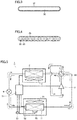
- first heat transfer tubes 33a and second heat transfer tubes 33b a flat tube is used, which has a flat cross-sectional shape having a major axis and a minor axis.
- Fig. 3 shows a flat tube having one refrigerant path 35 formed therein.
- Fig. 4 shows a flat tube having a plurality of refrigerant paths 35 formed therein.
- each of the first heat transfer tube and the second heat transfer tube is not limited to a flat tube, but may be a heat transfer tube having a cross section, for example, formed in a circular shape, an elliptical shape, and the like.
- the plurality of first heat transfer tubes 33a are disposed to be spaced apart from each other in the direction in which the minor axis extends.
- the plurality of first heat transfer tubes 33a are disposed in the first column.
- the first column serves as an auxiliary heat exchange unit 15a.
- the plurality of second heat transfer tubes 33b are disposed to be spaced apart from each other in the direction in which the minor axis extends.
- the plurality of second heat transfer tubes 33b are disposed in the second column.
- the second column serves as an auxiliary heat exchange unit 15b.
- auxiliary heat exchange unit 15a (a windward column) is located on the windward side while auxiliary heat exchange unit 15b (a leeward column) is located on the leeward side.
- the plurality of first heat transfer tubes 33a each have one end (the first end) connected to a distributor 25.
- Distributor 25 of auxiliary heat exchange unit 15 is connected to throttle device 9 (see Fig. 5 ).
- temperature sensor 53 configured to sense the temperature of the refrigerant is provided.
- the other ends (the second ends) of the plurality of first heat transfer tubes 33a and the other ends (the third ends) of the plurality of second heat transfer tubes 33b are connected through a pressure loss unit 17 (a pressure loss mechanism) configured to lose pressure of the refrigerant.
- a specific structure of pressure loss unit 17 will be described later.
- the plurality of second heat transfer tubes 33b each have one end (the fourth end) connected to main heat exchange unit 13.
- temperature sensor 55 configured to sense the temperature of the refrigerant is provided.
- Fig. 2 representatively shows the case where temperature sensor 55 is provided in the refrigerant pipe that is connected to one end of second heat transfer tube 33b disposed at the lowermost position, but temperature sensors may be provided at portions of the refrigerant pipes that are connected to their respective one ends of the plurality of second heat transfer tubes 33b.
- main heat exchange unit 13 a plurality of third heat transfer tubes 33c and a plurality of fourth heat transfer tubes 33d are disposed to penetrate the plurality of plate-shaped fins 31 that are disposed to be spaced apart from one another.
- a flat tube is used as in the case of first heat transfer tubes 33a and second heat transfer tubes 33b.
- Fig. 2 shows a series of third heat transfer tube 33c and fourth heat transfer tube 33d for simplification of illustration.
- the plurality of third heat transfer tubes 33c are disposed to be spaced apart from each other in the direction in which the minor axis extends.
- the plurality of third heat transfer tubes 33c are disposed in the first column (a windward column).
- the first column serves as main heat exchange unit 13a.
- the plurality of fourth heat transfer tubes 33d are disposed to be spaced apart from each other in the direction in which the minor axis extends.
- the plurality of fourth heat transfer tubes 33d are disposed in the second column (a leeward column).
- the second column serves as a main heat exchange unit 13b.
- the plurality of fourth heat transfer tubes 33d each have one end connected to a corresponding one of one ends of the plurality of second heat transfer tubes 33b through distributor 29.
- the plurality of fourth heat transfer tubes 33d each have the other end connected to a corresponding one of the other ends of the plurality of third heat transfer tubes 33c.
- the plurality of third heat transfer tubes 33c each have one end connected to a header 27. Header 27 is connected to four-way valve 23 (see Fig. 5 ).
- Outdoor heat exchanger 11 of air conditioning apparatus 1 is configured as described above.
- high-temperature and high-pressure gaseous refrigerant is discharged from compressor 3.
- the refrigerant flows thereafter as indicated by a dotted line arrow.
- the discharged high-temperature and high-pressure gas refrigerant (a single phase) flows through four-way valve 23 into outdoor heat exchanger 11.
- outdoor heat exchanger 11 heat exchange is conducted between the refrigerant flown therethrough and the air supplied by outdoor fan 21, so that the high-temperature and high-pressure gas refrigerant is condensed into high-pressure liquid refrigerant (a single phase).
- the high-pressure liquid refrigerant delivered out of outdoor heat exchanger 11 is turned into refrigerant in a two-phase state including low-pressure gas refrigerant and low-pressure liquid refrigerant.
- the refrigerant in a two-phase state flows into indoor heat exchanger 5.
- indoor heat exchanger 5 heat exchange is conducted between the incoming refrigerant in a two-phase state and the air supplied by indoor fan 7. Then, as a result of evaporation of the liquid refrigerant, the refrigerant in a two-phase state is turned into low-pressure gas refrigerant (a single phase). Through this heat exchange, the indoor area is cooled.
- the low-pressure gas refrigerant delivered out of indoor heat exchanger 5 flows through four-way valve 23 into compressor 3, and then compressed into high-temperature and high-pressure gas refrigerant, which is again discharged from compressor 3. This cycle is repeated thereafter.
- the refrigerant delivered from compressor 3 flows into header 27 and passes through header 27. Then, the refrigerant flows through third heat transfer tube 33c of main heat exchange unit 13a in the direction as indicated by an arrow. The refrigerant having flown through third heat transfer tube 33c then flows through fourth heat transfer tube 33d of main heat exchange unit 13b in the direction as indicated by an arrow, and thereafter flows into distributor 29.
- the refrigerant having flown into distributor 29 then flows through second heat transfer tube 33b of auxiliary heat exchange unit 15b in the direction as indicated by an arrow.
- the refrigerant having flown through second heat transfer tube 33b then flows through first heat transfer tube 33a of auxiliary heat exchange unit 15a in the direction as indicated by an arrow.
- the refrigerant having flown through first heat transfer tube 33a is discharged to the outside of outdoor heat exchanger 11.
- outdoor heat exchanger 11 functioning as an evaporator (a heating operation).
- a heating operation As shown in Fig. 5 , by driving compressor 3, high-temperature and high-pressure gaseous refrigerant is discharged from compressor 3. The refrigerant flows thereafter as indicated by a solid line arrow.
- the discharged high-temperature and high-pressure gas refrigerant flows through four-way valve 23 into indoor heat exchanger 5.
- indoor heat exchanger 5 heat exchange is conducted between the gas refrigerant having flown thereinto and the air supplied by indoor fan 7. Then, the high-temperature and high-pressure gas refrigerant is condensed into high-pressure liquid refrigerant (a single phase). Through this heat exchange, the indoor area is heated.
- throttle device 9 the high-pressure liquid refrigerant delivered out of indoor heat exchanger 5 is turned into refrigerant in a two-phase state including low-pressure gas refrigerant and low-pressure liquid refrigerant.
- the refrigerant in a two-phase state flows into outdoor heat exchanger 11.
- outdoor heat exchanger 11 heat exchange is conducted between the incoming refrigerant in a two-phase state and the air supplied by outdoor fan 21.
- the refrigerant in a two-phase state is turned into low-pressure gas refrigerant (a single phase).
- the low-pressure gas refrigerant delivered out of outdoor heat exchanger 11 flows through four-way valve 23 into compressor 3 and then compressed into high-temperature and high-pressure gas refrigerant, which is again discharged from compressor 3. This cycle is repeated thereafter.
- the refrigerant delivered from throttle device 9 flows into distributor 25 of auxiliary heat exchange unit 15 and passes through distributor 25. Then, the refrigerant flows through first heat transfer tube 33a of auxiliary heat exchange unit 15a in the direction as indicated by an arrow. The refrigerant having flown through first heat transfer tube 33a then flows through second heat transfer tube 33b of auxiliary heat exchange unit 15b in the direction as indicated by an arrow.
- the refrigerant having flown through second heat transfer tube 33b then flows into distributor 29 of main heat exchange unit 13.
- the refrigerant having flown into distributor 29 then flows through fourth heat transfer tube 33d of main heat exchange unit 13b in the direction as indicated by an arrow.
- the refrigerant having flown through fourth heat transfer tube 33d then flows through third heat transfer tube 33c of main heat exchange unit 13a in the direction as indicated by an arrow.
- the refrigerant having flown through third heat transfer tube 33c then flows into header 27 and passes through header 27. Then, the refrigerant is delivered to the outside of outdoor heat exchanger 11.
- the outdoor air temperature is higher than the above-described condition
- the air dry-bulb temperature is 5 °C
- the air wet-bulb temperature is 4 °C.
- the dew point temperature of air is about 2.8 °C.
- both the air dry-bulb temperature and the dew point temperature may reach the temperature close to the refrigerant temperature.
- frost may adhere to the outdoor heat exchanger.
- the air dry-bulb temperature is 2 °C
- the air wet-bulb temperature is 1 °C
- the dew point temperature is -0.4 °C.
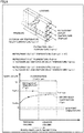
- Fig. 8 shows: a graph showing transition of the temperature of the refrigerant that flows through auxiliary heat exchange unit 15 with respect to the refrigerant flow direction (a dashed line); a graph showing transition of the air dry-bulb temperature with respect to the air flow direction (a solid line); and a graph showing transition of the dew point temperature with respect to the air flow direction (a dotted line).
- the refrigerant inlet temperature (Tref-in) of the refrigerant flowing into auxiliary heat exchange unit 15 is lower than the outdoor air temperature (air inlet temperature (Tair-in)).
- the air dry-bulb temperature immediately reaches approximately the same temperature as the dew point temperature. Since the dew point temperature is lower than the freezing point of water (for example, 0 °C), frost is to adhere to the most part of outdoor heat exchanger 11 including auxiliary heat exchange unit 15.
- the defrosting operation is generally performed in the same operation mode as that in the operation of the outdoor heat exchanger functioning as a condenser.
- the direction in which the refrigerant flows is opposite to the direction in which the refrigerant flows during the operation of outdoor heat exchanger 11 functioning as an evaporator.
- the refrigerant flows through auxiliary heat exchange unit 15 after it flows through main heat exchange unit 13 (see Fig. 6 ).
- Auxiliary heat exchange unit 15 is disposed below main heat exchange unit 13. Accordingly, the quantity of heat of the refrigerant is removed in main heat exchange unit 13 on the upstream side of the refrigerant flow.
- auxiliary heat exchange unit 15 on the downstream side the performance of defrosting adhering frost deteriorates, which may lengthen the defrosting time.
- the indoor temperature gradually lowers, so that a comfortable state may not be able to be maintained.
- frost may further grow to thereby damage auxiliary heat exchange unit 15 and the like.
- a significant problem may occur, for example, that a heat transfer tube is damaged to thereby cause leakage of refrigerant, and the like.
- Fig. 9 shows: a graph showing transition of the temperature of the refrigerant that flows through auxiliary heat exchange unit 15 with respect to the refrigerant flow direction (a dashed line); a graph showing transition of the air dry-bulb temperature with respect to the air flow direction (a solid line); and a graph showing transition of the dew point temperature with respect to the air flow direction (a dotted line).
- the refrigerant outlet temperature (Tref-out) of the refrigerant delivered out of auxiliary heat exchange unit 15 is higher than the outdoor air temperature (air inlet temperature (Tair-in)).
- air inlet temperature (Tair-in) the outdoor air temperature
- frost does not adhere to auxiliary heat exchange unit 15, so that auxiliary heat exchange unit 15 is not damaged.
- the reliability as auxiliary heat exchange unit 15 is ensured.
- auxiliary heat exchange unit 15 used as a condenser the refrigerant changes so as to be liquefied. Accordingly, in main heat exchange unit 13 used as an evaporator, for evaporating the liquefied refrigerant, the load for heat exchange in main heat exchange unit 13 is increased. Therefore, the heat exchange performance significantly deteriorates.
- Fig. 10 shows: a graph showing transition of the temperature of the refrigerant that flows through auxiliary heat exchange unit 15 with respect to the refrigerant flow direction (a dashed line); a graph showing transition of the air dry-bulb temperature with respect to the air flow direction (a solid line); and a graph showing transition of the dew point temperature with respect to the air flow direction (a dotted line).
- This operation of outdoor heat exchanger 11 functioning as an evaporator is performed on the conditions that, in the case where the refrigerant outlet temperature (Tref-out) is lower than the freezing point of water (for example, 0 °C), the refrigerant inlet temperature (Tref-in) of the refrigerant flowing into auxiliary heat exchange unit 15 is higher than the outdoor air temperature (air inlet temperature (Tair-in)), and the refrigerant outlet temperature of the refrigerant delivered out of auxiliary heat exchange unit 15 (Tref-out) is lower than the outdoor air temperature (air inlet temperature (Tair-in)).
- auxiliary heat exchange unit 15 The refrigerant flowing through auxiliary heat exchange unit 15 is in a two-phase state including liquid refrigerant and gas refrigerant.
- adjusting the pressure loss of the refrigerant in auxiliary heat exchange unit 15 means the same as adjusting the refrigerant temperature.
- pressure loss unit 17 is provided between auxiliary heat exchange unit 15a located in the first column and auxiliary heat exchange unit 15b located in the second column, so that auxiliary heat exchange unit 15a is caused to function as a condenser and auxiliary heat exchange unit 15b is caused to function as an evaporator.
- auxiliary heat exchange unit 15a located in the windward column When auxiliary heat exchange unit 15a located in the windward column is caused to function as a condenser, the air temperature rises. Thus, even when auxiliary heat exchange unit 15b located in the leeward column is caused to function as an evaporator, the air temperature is less likely to fall below the dew point temperature. Thereby, auxiliary heat exchange unit 15 can be caused to entirely function as an evaporator in the state where the temperature of the refrigerant lowers, and also, adhesion of frost to auxiliary heat exchange unit 15 can be prevented.
- the refrigerant flows through auxiliary heat exchange unit 15a located on the windward side, and thereafter, flows through auxiliary heat exchange unit 15b located on the leeward side.
- the refrigerant flows from the windward side toward the leeward side in the same manner as with the flow of air.
- Such the refrigerant flow is referred to as a parallel flow.
- the flow of the refrigerant from the leeward side toward the windward side is referred to as a counterflow.
- auxiliary heat exchange unit 15 in outdoor heat exchanger 11, the refrigerant first flows through auxiliary heat exchange unit 15, and then flows through main heat exchange unit 13.
- the refrigerant having flown through second heat transfer tube 33b then flows through first heat transfer tube 33a of auxiliary heat exchange unit 15a in the direction as indicated by an arrow.
- the refrigerant having flown through auxiliary heat exchange unit 15a is caused to flow through main heat exchange unit 13 and thereafter delivered out of outdoor heat exchanger 11, in the same manner as shown in Fig. 7 .
- Fig. 12 represents the case where the refrigerant flows as a counterflow, and shows: a graph showing transition of the temperature of the refrigerant that flows through auxiliary heat exchange unit 15 with respect to the refrigerant flow direction (a dashed line); a graph showing transition of the air dry-bulb temperature with respect to the air flow direction (a solid line); and a graph showing transition of the dew point temperature with respect to the air flow direction (a dotted line).
- auxiliary heat exchange unit 15 when the temperature of the refrigerant flowing through auxiliary heat exchange unit 15a located on the windward side is set to be higher than the outdoor air temperature (air inlet temperature (Tair-in)), the temperature of the refrigerant flowing through auxiliary heat exchange unit 15b located on the leeward side is also higher than the outdoor air temperature (air inlet temperature (Tair-in)).
- auxiliary heat exchange unit 15 entirely functions as a condenser, so that the heat exchange performance deteriorates, as having been described with reference to Fig. 9 . Therefore, in order that outdoor heat exchanger 11 is operated to function as an evaporator so as to prevent adhesion of frost to auxiliary heat exchange unit 15, it is desirable to perform the operation such that the refrigerant flows as a parallel flow along the flow of air.
- pressure loss unit 17 is disposed between auxiliary heat exchange unit 15a and auxiliary heat exchange unit 15b.
- a pressure loss unit for example, the friction loss inside the heat transfer tube such as first heat transfer tube 33a and second heat transfer tube 33b may be employed.
- Fig. 13 represents the case where outdoor heat exchanger 11 is operated to function as an evaporator, and shows: a graph showing transition of the temperature of the refrigerant flowing through auxiliary heat exchange unit 15 with respect to the refrigerant flow direction (a dashed line); a graph showing transition of the air dry-bulb temperature with respect to the air flow direction (a solid line); and a graph showing transition of the dew point temperature with respect to the air flow direction (a dotted line).
- the temperature of the refrigerant lowers gradually by the friction loss inside the heat transfer tube.
- the friction loss inside the heat transfer tube is defined by the flow velocity of the refrigerant, the inside shape of the heat transfer tube, and the length of the heat transfer tube. Accordingly, the amount of the refrigerant circulating in the air conditioning apparatus, the dimensions of the heat transfer tube inside the outdoor heat exchanger, the number of paths in the heat transfer tube, and the like are set at their respective prescribed values based on the design. Then, on the condition that the refrigerant temperature establishes a prescribed temperature relation, outdoor heat exchanger 11 is operated to function as an evaporator, with the result that adhesion of frost to auxiliary heat exchange unit 15 can be prevented.
- the operation is performed such that the refrigerant inlet temperature (Tref-in) is higher than the outdoor air temperature (air inlet temperature (Tair-in)), and that the refrigerant outlet temperature (Tref-out) is lower than the outdoor air temperature (air inlet temperature (Tair-in)), so that adhesion of frost to auxiliary heat exchange unit 15 can be prevented.
- auxiliary heat exchange unit 15 Furthermore, by performing the operation such that the refrigerant outlet temperature (Tref-out) of the refrigerant delivered out of auxiliary heat exchange unit 15 is higher than the dew point temperature, adhesion of frost to auxiliary heat exchange unit 15 can be reliably prevented.
- a throttle device As pressure loss unit 17 disposed between auxiliary heat exchange unit 15a and auxiliary heat exchange unit 15b, a throttle device may be used, for example.
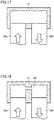
- Fig. 14 shows throttle devices 39 each of which is provided for a corresponding one of a plurality of first heat transfer tubes 33a disposed in auxiliary heat exchange unit 15a and a corresponding one of a plurality of second heat transfer tubes 33b disposed in auxiliary heat exchange unit 15b, such that each of throttle devices 39 is disposed for a route (path) extending from a corresponding one of first heat transfer tubes 33a to a corresponding one of second heat transfer tubes 33b.
- Fig. 15 shows throttle device 39 provided such that the refrigerants having flown through first heat transfer tubes 33a are joined on the upstream side of the throttle device, and then branched (divided) again on the downstream side of the throttle device so as to be delivered to their respective second heat transfer tubes 33b.
- auxiliary heat exchange unit 15 the opening degree of throttle device 39 is adjusted with respect to the temperature of the refrigerant on the upstream side of throttle device 39, so that the temperature of the refrigerant on the downstream side of throttle device 39 can be adjusted.
- throttle device 39 when throttle device 39 is placed between auxiliary heat exchange unit 15a and auxiliary heat exchange unit 15b (between the columns), the temperature of the refrigerant flowing through auxiliary heat exchange unit 15a located on the windward side and the temperature of the refrigerant flowing through auxiliary heat exchange unit 15b located on the leeward side can be separately adjusted.
- auxiliary heat exchange unit 15a located on the windward side can be entirely functioned as a condenser while auxiliary heat exchange unit 15b located on the leeward side can be entirely functioned as an evaporator. Consequently, as having been described in the first embodiment, adhesion of frost to auxiliary heat exchange unit 15 of outdoor heat exchanger 11 can be prevented during the operation of outdoor heat exchanger 11 functioning as an evaporator.
- a header (an inter-columnar header) may be used, for example.
- Fig. 16 shows an inter-columnar header 41 disposed between auxiliary heat exchange unit 15a and auxiliary heat exchange unit 15b.
- a flow path through which refrigerant flows is provided inside inter-columnar header 41 for each route (path) extending from first heat transfer tube 33a to second heat transfer tube 33b.
- a throttle portion 43 is provided at some midpoint of the flow path in such a manner that the cross-sectional area of this midpoint in the flow path is narrower than the cross-sectional area of another portion in the flow path.
- auxiliary heat exchange unit 15a can be functioned as a condenser while auxiliary heat exchange unit 15b can be functioned as an evaporator. Consequently, during the operation of outdoor heat exchanger 11 functioning as an evaporator, adhesion of frost to auxiliary heat exchange unit 15 of outdoor heat exchanger 11 can be prevented.
- auxiliary heat exchange unit 15a As pressure loss unit 17 disposed between auxiliary heat exchange unit 15a and auxiliary heat exchange unit 15b, for example, two headers may be used, including a header connected to auxiliary heat exchange unit 15a and a header connected to auxiliary heat exchange unit 15b.
- Fig. 20 shows a header including a header 45a, a header 45b, and a header connection tube 47.
- Header 45a is connected to first heat transfer tube 33a of auxiliary heat exchange unit 15a.
- Header 45b is connected to second heat transfer tube 33b of auxiliary heat exchange unit 15b.
- Header connection tube 47 provides connection between header 45a and header 45b.
- auxiliary heat exchange unit 15a and the temperature of the refrigerant flowing through auxiliary heat exchange unit 15b can be separately adjusted.
- adhesion of frost to auxiliary heat exchange unit 15 of outdoor heat exchanger 11 can be prevented during the operation of outdoor heat exchanger 11 functioning as an evaporator.
- flow paths causing friction loss may be separately provided inside the flow paths of headers 45a and 45b. Then, also by adjusting the shapes of these flow paths to thereby adjust the pressure loss, adhesion of frost can be prevented.
- a U-shaped tube may be used other than a header.
- a U-shaped tube 49 is connected for each route (path) extending from first heat transfer tube 33a to second heat transfer tube 33b.
- the temperature of the refrigerant flowing through auxiliary heat exchange unit 15a and the temperature of the refrigerant flowing through auxiliary heat exchange unit 15b can be separately adjusted.
- adhesion of frost to auxiliary heat exchange unit 15 of outdoor heat exchanger 11 can be prevented during the operation of outdoor heat exchanger 11 functioning as an evaporator.
- refrigerant used in air conditioning apparatus 1 having been described in the above embodiment, by using any kind of refrigerant such as refrigerant R410A, refrigerant R407C, refrigerant R32, refrigerant R507A, refrigerant HFO1234yf, and the like, adhesion of frost to auxiliary heat exchange unit 15 of outdoor heat exchanger 11 can be prevented.
- refrigerant R410A refrigerant R407C
- refrigerant R32 refrigerant R507A
- refrigerant HFO1234yf refrigerant HFO1234yf
- Each of refrigerant R410A and refrigerant R407C is a refrigerant mixture and particularly referred to as a non-azeotropic refrigerant mixture.
- a non-azeotropic refrigerant mixture has different compositions in a vapor phase and in a liquid phase in a moist vapor state, and also has a characteristic that it undergoes a phase change of evaporation or condensation while it undergoes a temperature change and a composition conversion between two phases of gas refrigerant and liquid refrigerant under fixed pressure.
- refrigerant R407C and the like undergo extremely small temperature change during a phase change, and particularly, is referred to as a pseudo-azeotropic refrigerant mixture.
- Refrigerant R32 and refrigerant HFO1234yf each are refrigerant formed of a single component.
- Refrigerant R507A is a refrigerant mixture and referred to as an azeotropic refrigerant mixture.
- the azeotropic refrigerant mixture has a composition that is identical in a vapor phase and a liquid phase in moist vapor in a certain component ratio, and also has a characteristic that it undergoes a phase change of evaporation or condensation at a fixed temperature under fixed pressure, as in the case of the refrigerant formed of a single component.
- a non-azeotropic refrigerant mixture a pseudo-azeotropic refrigerant mixture, refrigerant formed of a single component, or an azeotropic refrigerant mixture
- the refrigerant outlet temperature is lower than the freezing point of water (for example, 0 °C)
- the operation is performed such that the refrigerant inlet temperature is higher than the outdoor air temperature and that the refrigerant outlet temperature is lower than the outdoor air temperature, with the result that adhesion of frost to auxiliary heat exchange unit 15 of outdoor heat exchanger 11 can be prevented.
- adhesion of frost to auxiliary heat exchange unit 15 can be reliably prevented.
- refrigeration oil used in the air conditioning apparatus refrigeration oil having compatibility is employed in consideration of the mutual solubility to the refrigerant to be applied.
- fluorocarbon-based refrigerant such as refrigerant R410A
- alkylbenzene oil-based refrigeration oil for example, alkylbenzene oil-based refrigeration oil, ester oil-based refrigeration oil or ether oil-based refrigeration oil is used.
- mineral oil-based refrigeration oil or fluorine oil-based refrigeration oil may be used.
- the operation is performed such that the refrigerant inlet temperature is higher than the outdoor air temperature and that the refrigerant outlet temperature is lower than the outdoor air temperature, with the result that adhesion of frost to auxiliary heat exchange unit 15 of outdoor heat exchanger 11 can be prevented.
- the refrigeration cycle apparatus is not limited to an air conditioning apparatus, but may be applicable, for example, also to an apparatus including an outdoor heat exchanger such as a heat pump water heater configured to perform heat exchange with air. Furthermore, various combinations can be made as appropriate for the refrigeration cycle apparatus including an outdoor heat exchanger, which has been described in the embodiments.
- the present invention is effectively utilized in a refrigeration cycle apparatus such as an air conditioning apparatus including an outdoor heat exchanger equipped with a main heat exchange unit and an auxiliary heat exchange unit.
- 1 air conditioning apparatus 3 compressor, 5 indoor heat exchanger, 7 indoor fan, 9 throttle device, 11 outdoor heat exchanger, 13 main heat exchange unit, 13a, 13b main heat exchange unit, 15 auxiliary heat exchange unit, 15a, 15b auxiliary heat exchange unit, 17 pressure loss unit, 21 outdoor fan, 23 four-way valve, 25 distributor, 27 header, 29 distributor, 31 fin, 33a first heat transfer tube, 33b second heat transfer tube, 33c third heat transfer tube, 33d fourth heat transfer tube, 35 refrigerant path, 37 refrigerant pipe, 39 throttle device, 41 inter-columnar header, 43 throttle portion, 45a, 45b header, 47 header connection tube, 49 U-shaped tube, 51 control unit, 53, 55, 57 temperature sensor.
Landscapes
- Engineering & Computer Science (AREA)
- Physics & Mathematics (AREA)
- Mechanical Engineering (AREA)
- Thermal Sciences (AREA)
- General Engineering & Computer Science (AREA)
- Other Air-Conditioning Systems (AREA)
- Air-Conditioning For Vehicles (AREA)
- Details Of Heat-Exchange And Heat-Transfer (AREA)
- Heat-Exchange Devices With Radiators And Conduit Assemblies (AREA)
- Compression-Type Refrigeration Machines With Reversible Cycles (AREA)
Applications Claiming Priority (1)
| Application Number | Priority Date | Filing Date | Title |
|---|---|---|---|
| PCT/JP2016/068810 WO2017221400A1 (ja) | 2016-06-24 | 2016-06-24 | 冷凍サイクル装置およびそれに用いられる室外熱交換器 |
Publications (3)
| Publication Number | Publication Date |
|---|---|
| EP3477227A1 true EP3477227A1 (de) | 2019-05-01 |
| EP3477227A4 EP3477227A4 (de) | 2019-08-07 |
| EP3477227B1 EP3477227B1 (de) | 2020-12-23 |
Family
ID=60783946
Family Applications (1)
| Application Number | Title | Priority Date | Filing Date |
|---|---|---|---|
| EP16906317.9A Not-in-force EP3477227B1 (de) | 2016-06-24 | 2016-06-24 | Kühlkreisvorrichtung und darin verwendeter aussenwärmetauscher |
Country Status (6)
| Country | Link |
|---|---|
| US (1) | US20190128574A1 (de) |
| EP (1) | EP3477227B1 (de) |
| JP (1) | JPWO2017221400A1 (de) |
| CN (1) | CN109312971B (de) |
| ES (1) | ES2844591T3 (de) |
| WO (1) | WO2017221400A1 (de) |
Cited By (2)
| Publication number | Priority date | Publication date | Assignee | Title |
|---|---|---|---|---|
| EP4166868A1 (de) * | 2021-10-15 | 2023-04-19 | Carrier Corporation | Verdampferwärmetauscher zur verhinderung von eisbildung |
| EP4310427A4 (de) * | 2021-03-15 | 2024-05-01 | Mitsubishi Electric Corporation | Wärmetauscher und klimatisierungsvorrichtung |
Families Citing this family (6)
| Publication number | Priority date | Publication date | Assignee | Title |
|---|---|---|---|---|
| JP7406297B2 (ja) * | 2018-03-01 | 2023-12-27 | ダイキン工業株式会社 | 熱交換器 |
| JP7170841B2 (ja) * | 2019-03-26 | 2022-11-14 | 三菱電機株式会社 | 熱交換器および冷凍サイクル装置 |
| JP7425282B2 (ja) * | 2019-09-30 | 2024-01-31 | ダイキン工業株式会社 | 蒸発器、およびそれを備えた冷凍サイクル装置 |
| CN111238090B (zh) * | 2020-01-09 | 2021-02-02 | 西安交通大学 | 一种微通道蒸发器及其控制方法 |
| WO2023234121A1 (ja) * | 2022-05-31 | 2023-12-07 | 株式会社デンソーエアクール | 車載用熱交換器 |
| JP7701659B2 (ja) * | 2023-09-29 | 2025-07-02 | ダイキン工業株式会社 | 熱交換器および空気調和装置 |
Family Cites Families (14)
| Publication number | Priority date | Publication date | Assignee | Title |
|---|---|---|---|---|
| JPS5316536B2 (de) * | 1973-04-11 | 1978-06-01 | ||
| JPS57109467U (de) * | 1980-12-26 | 1982-07-06 | ||
| JPS61197967A (ja) * | 1985-02-26 | 1986-09-02 | 株式会社ボッシュオートモーティブ システム | 冷房サイクル |
| JPH0278844A (ja) * | 1988-09-14 | 1990-03-19 | Hokkaido Electric Power Co Inc:The | 空気調和機 |
| JP2002372320A (ja) * | 2001-06-15 | 2002-12-26 | Matsushita Electric Ind Co Ltd | 冷凍装置 |
| JP4143955B2 (ja) * | 2001-11-30 | 2008-09-03 | 株式会社ティラド | 熱交換器 |
| US7832653B2 (en) * | 2005-02-28 | 2010-11-16 | Daikin Industries, Ltd. | Expansion valve having a grooved valve member and refrigeration device including the same |
| EP2372272A4 (de) * | 2008-12-19 | 2014-10-15 | Daikin Ind Ltd | Kühlanlage |
| JP2013083419A (ja) * | 2011-09-30 | 2013-05-09 | Daikin Industries Ltd | 熱交換器および空気調和機 |
| US9494368B2 (en) * | 2013-09-11 | 2016-11-15 | Daikin Industries, Ltd. | Heat exchanger and air conditioner |
| KR20150047027A (ko) * | 2013-10-23 | 2015-05-04 | 엘지전자 주식회사 | 히트 펌프 |
| JP6336100B2 (ja) * | 2014-10-07 | 2018-06-06 | 三菱電機株式会社 | 熱交換器、及び、空気調和装置 |
| EP3205967B1 (de) * | 2014-10-07 | 2019-09-04 | Mitsubishi Electric Corporation | Wärmetauscher und klimatisierungsvorrichtung |
| WO2016135935A1 (ja) * | 2015-02-27 | 2016-09-01 | ジョンソンコントロールズ ヒタチ エア コンディショニング テクノロジー(ホンコン)リミテッド | 熱交換装置およびこれを用いた空気調和機 |
-
2016
- 2016-06-24 EP EP16906317.9A patent/EP3477227B1/de not_active Not-in-force
- 2016-06-24 ES ES16906317T patent/ES2844591T3/es active Active
- 2016-06-24 CN CN201680085743.0A patent/CN109312971B/zh not_active Expired - Fee Related
- 2016-06-24 US US16/089,634 patent/US20190128574A1/en not_active Abandoned
- 2016-06-24 WO PCT/JP2016/068810 patent/WO2017221400A1/ja not_active Ceased
- 2016-06-24 JP JP2018523250A patent/JPWO2017221400A1/ja active Pending
Cited By (2)
| Publication number | Priority date | Publication date | Assignee | Title |
|---|---|---|---|---|
| EP4310427A4 (de) * | 2021-03-15 | 2024-05-01 | Mitsubishi Electric Corporation | Wärmetauscher und klimatisierungsvorrichtung |
| EP4166868A1 (de) * | 2021-10-15 | 2023-04-19 | Carrier Corporation | Verdampferwärmetauscher zur verhinderung von eisbildung |
Also Published As
| Publication number | Publication date |
|---|---|
| EP3477227B1 (de) | 2020-12-23 |
| EP3477227A4 (de) | 2019-08-07 |
| JPWO2017221400A1 (ja) | 2019-02-28 |
| US20190128574A1 (en) | 2019-05-02 |
| WO2017221400A1 (ja) | 2017-12-28 |
| CN109312971A (zh) | 2019-02-05 |
| ES2844591T3 (es) | 2021-07-22 |
| CN109312971B (zh) | 2020-11-06 |
Similar Documents
| Publication | Publication Date | Title |
|---|---|---|
| EP3477227B1 (de) | Kühlkreisvorrichtung und darin verwendeter aussenwärmetauscher | |
| US10760832B2 (en) | Air-conditioning apparatus | |
| JP5992089B2 (ja) | 空気調和装置 | |
| JP6157723B2 (ja) | 空気調和装置 | |
| JP2001221526A (ja) | 冷凍空調装置 | |
| JP6479181B2 (ja) | 空気調和装置 | |
| CN109073290B (zh) | 室外单元及具备该室外单元的制冷循环装置 | |
| CN113167486A (zh) | 空调机 | |
| EP3719408B1 (de) | Klimaanlage | |
| JP2013253726A (ja) | 熱交換システム | |
| JP6910436B2 (ja) | 室外ユニットおよび冷凍サイクル装置 | |
| CN117355721A (zh) | 热交换器、具备热交换器的空调装置的室外机、以及具备空调装置的室外机的空调装置 | |
| EP3770535A1 (de) | Wärmetauscher, kältekreislaufvorrichtung und klimaanlage | |
| JPWO2020110301A1 (ja) | 冷凍サイクル装置 | |
| US20190056160A1 (en) | Air-conditioning apparatus |
Legal Events
| Date | Code | Title | Description |
|---|---|---|---|
| STAA | Information on the status of an ep patent application or granted ep patent |
Free format text: STATUS: THE INTERNATIONAL PUBLICATION HAS BEEN MADE |
|
| PUAI | Public reference made under article 153(3) epc to a published international application that has entered the european phase |
Free format text: ORIGINAL CODE: 0009012 |
|
| STAA | Information on the status of an ep patent application or granted ep patent |
Free format text: STATUS: REQUEST FOR EXAMINATION WAS MADE |
|
| 17P | Request for examination filed |
Effective date: 20181213 |
|
| AK | Designated contracting states |
Kind code of ref document: A1 Designated state(s): AL AT BE BG CH CY CZ DE DK EE ES FI FR GB GR HR HU IE IS IT LI LT LU LV MC MK MT NL NO PL PT RO RS SE SI SK SM TR |
|
| AX | Request for extension of the european patent |
Extension state: BA ME |
|
| A4 | Supplementary search report drawn up and despatched |
Effective date: 20190710 |
|
| RIC1 | Information provided on ipc code assigned before grant |
Ipc: F25B 47/00 20060101ALI20190704BHEP Ipc: F25B 13/00 20060101ALI20190704BHEP Ipc: F25B 39/00 20060101ALI20190704BHEP Ipc: F28F 17/00 20060101ALI20190704BHEP Ipc: F25B 39/02 20060101ALI20190704BHEP Ipc: F25B 47/02 20060101AFI20190704BHEP |
|
| DAV | Request for validation of the european patent (deleted) | ||
| DAX | Request for extension of the european patent (deleted) | ||
| GRAP | Despatch of communication of intention to grant a patent |
Free format text: ORIGINAL CODE: EPIDOSNIGR1 |
|
| STAA | Information on the status of an ep patent application or granted ep patent |
Free format text: STATUS: GRANT OF PATENT IS INTENDED |
|
| INTG | Intention to grant announced |
Effective date: 20200805 |
|
| GRAS | Grant fee paid |
Free format text: ORIGINAL CODE: EPIDOSNIGR3 |
|
| GRAA | (expected) grant |
Free format text: ORIGINAL CODE: 0009210 |
|
| STAA | Information on the status of an ep patent application or granted ep patent |
Free format text: STATUS: THE PATENT HAS BEEN GRANTED |
|
| AK | Designated contracting states |
Kind code of ref document: B1 Designated state(s): AL AT BE BG CH CY CZ DE DK EE ES FI FR GB GR HR HU IE IS IT LI LT LU LV MC MK MT NL NO PL PT RO RS SE SI SK SM TR |
|
| REG | Reference to a national code |
Ref country code: GB Ref legal event code: FG4D |
|
| REG | Reference to a national code |
Ref country code: DE Ref legal event code: R096 Ref document number: 602016050437 Country of ref document: DE |
|
| REG | Reference to a national code |
Ref country code: AT Ref legal event code: REF Ref document number: 1348131 Country of ref document: AT Kind code of ref document: T Effective date: 20210115 |
|
| REG | Reference to a national code |
Ref country code: IE Ref legal event code: FG4D |
|
| PG25 | Lapsed in a contracting state [announced via postgrant information from national office to epo] |
Ref country code: RS Free format text: LAPSE BECAUSE OF FAILURE TO SUBMIT A TRANSLATION OF THE DESCRIPTION OR TO PAY THE FEE WITHIN THE PRESCRIBED TIME-LIMIT Effective date: 20201223 Ref country code: NO Free format text: LAPSE BECAUSE OF FAILURE TO SUBMIT A TRANSLATION OF THE DESCRIPTION OR TO PAY THE FEE WITHIN THE PRESCRIBED TIME-LIMIT Effective date: 20210323 Ref country code: FI Free format text: LAPSE BECAUSE OF FAILURE TO SUBMIT A TRANSLATION OF THE DESCRIPTION OR TO PAY THE FEE WITHIN THE PRESCRIBED TIME-LIMIT Effective date: 20201223 Ref country code: GR Free format text: LAPSE BECAUSE OF FAILURE TO SUBMIT A TRANSLATION OF THE DESCRIPTION OR TO PAY THE FEE WITHIN THE PRESCRIBED TIME-LIMIT Effective date: 20210324 |
|
| REG | Reference to a national code |
Ref country code: AT Ref legal event code: MK05 Ref document number: 1348131 Country of ref document: AT Kind code of ref document: T Effective date: 20201223 |
|
| REG | Reference to a national code |
Ref country code: NL Ref legal event code: MP Effective date: 20201223 |
|
| PG25 | Lapsed in a contracting state [announced via postgrant information from national office to epo] |
Ref country code: BG Free format text: LAPSE BECAUSE OF FAILURE TO SUBMIT A TRANSLATION OF THE DESCRIPTION OR TO PAY THE FEE WITHIN THE PRESCRIBED TIME-LIMIT Effective date: 20210323 Ref country code: LV Free format text: LAPSE BECAUSE OF FAILURE TO SUBMIT A TRANSLATION OF THE DESCRIPTION OR TO PAY THE FEE WITHIN THE PRESCRIBED TIME-LIMIT Effective date: 20201223 Ref country code: SE Free format text: LAPSE BECAUSE OF FAILURE TO SUBMIT A TRANSLATION OF THE DESCRIPTION OR TO PAY THE FEE WITHIN THE PRESCRIBED TIME-LIMIT Effective date: 20201223 |
|
| PG25 | Lapsed in a contracting state [announced via postgrant information from national office to epo] |
Ref country code: NL Free format text: LAPSE BECAUSE OF FAILURE TO SUBMIT A TRANSLATION OF THE DESCRIPTION OR TO PAY THE FEE WITHIN THE PRESCRIBED TIME-LIMIT Effective date: 20201223 Ref country code: HR Free format text: LAPSE BECAUSE OF FAILURE TO SUBMIT A TRANSLATION OF THE DESCRIPTION OR TO PAY THE FEE WITHIN THE PRESCRIBED TIME-LIMIT Effective date: 20201223 |
|
| REG | Reference to a national code |
Ref country code: LT Ref legal event code: MG9D |
|
| REG | Reference to a national code |
Ref country code: ES Ref legal event code: FG2A Ref document number: 2844591 Country of ref document: ES Kind code of ref document: T3 Effective date: 20210722 |
|
| PG25 | Lapsed in a contracting state [announced via postgrant information from national office to epo] |
Ref country code: SM Free format text: LAPSE BECAUSE OF FAILURE TO SUBMIT A TRANSLATION OF THE DESCRIPTION OR TO PAY THE FEE WITHIN THE PRESCRIBED TIME-LIMIT Effective date: 20201223 Ref country code: LT Free format text: LAPSE BECAUSE OF FAILURE TO SUBMIT A TRANSLATION OF THE DESCRIPTION OR TO PAY THE FEE WITHIN THE PRESCRIBED TIME-LIMIT Effective date: 20201223 Ref country code: EE Free format text: LAPSE BECAUSE OF FAILURE TO SUBMIT A TRANSLATION OF THE DESCRIPTION OR TO PAY THE FEE WITHIN THE PRESCRIBED TIME-LIMIT Effective date: 20201223 Ref country code: CZ Free format text: LAPSE BECAUSE OF FAILURE TO SUBMIT A TRANSLATION OF THE DESCRIPTION OR TO PAY THE FEE WITHIN THE PRESCRIBED TIME-LIMIT Effective date: 20201223 Ref country code: PT Free format text: LAPSE BECAUSE OF FAILURE TO SUBMIT A TRANSLATION OF THE DESCRIPTION OR TO PAY THE FEE WITHIN THE PRESCRIBED TIME-LIMIT Effective date: 20210423 Ref country code: RO Free format text: LAPSE BECAUSE OF FAILURE TO SUBMIT A TRANSLATION OF THE DESCRIPTION OR TO PAY THE FEE WITHIN THE PRESCRIBED TIME-LIMIT Effective date: 20201223 Ref country code: SK Free format text: LAPSE BECAUSE OF FAILURE TO SUBMIT A TRANSLATION OF THE DESCRIPTION OR TO PAY THE FEE WITHIN THE PRESCRIBED TIME-LIMIT Effective date: 20201223 |
|
| PG25 | Lapsed in a contracting state [announced via postgrant information from national office to epo] |
Ref country code: AT Free format text: LAPSE BECAUSE OF FAILURE TO SUBMIT A TRANSLATION OF THE DESCRIPTION OR TO PAY THE FEE WITHIN THE PRESCRIBED TIME-LIMIT Effective date: 20201223 Ref country code: PL Free format text: LAPSE BECAUSE OF FAILURE TO SUBMIT A TRANSLATION OF THE DESCRIPTION OR TO PAY THE FEE WITHIN THE PRESCRIBED TIME-LIMIT Effective date: 20201223 |
|
| REG | Reference to a national code |
Ref country code: DE Ref legal event code: R097 Ref document number: 602016050437 Country of ref document: DE |
|
| PG25 | Lapsed in a contracting state [announced via postgrant information from national office to epo] |
Ref country code: IS Free format text: LAPSE BECAUSE OF FAILURE TO SUBMIT A TRANSLATION OF THE DESCRIPTION OR TO PAY THE FEE WITHIN THE PRESCRIBED TIME-LIMIT Effective date: 20210423 |
|
| PG25 | Lapsed in a contracting state [announced via postgrant information from national office to epo] |
Ref country code: AL Free format text: LAPSE BECAUSE OF FAILURE TO SUBMIT A TRANSLATION OF THE DESCRIPTION OR TO PAY THE FEE WITHIN THE PRESCRIBED TIME-LIMIT Effective date: 20201223 Ref country code: IT Free format text: LAPSE BECAUSE OF FAILURE TO SUBMIT A TRANSLATION OF THE DESCRIPTION OR TO PAY THE FEE WITHIN THE PRESCRIBED TIME-LIMIT Effective date: 20201223 |
|
| PLBE | No opposition filed within time limit |
Free format text: ORIGINAL CODE: 0009261 |
|
| STAA | Information on the status of an ep patent application or granted ep patent |
Free format text: STATUS: NO OPPOSITION FILED WITHIN TIME LIMIT |
|
| PG25 | Lapsed in a contracting state [announced via postgrant information from national office to epo] |
Ref country code: DK Free format text: LAPSE BECAUSE OF FAILURE TO SUBMIT A TRANSLATION OF THE DESCRIPTION OR TO PAY THE FEE WITHIN THE PRESCRIBED TIME-LIMIT Effective date: 20201223 |
|
| 26N | No opposition filed |
Effective date: 20210924 |
|
| PG25 | Lapsed in a contracting state [announced via postgrant information from national office to epo] |
Ref country code: MC Free format text: LAPSE BECAUSE OF FAILURE TO SUBMIT A TRANSLATION OF THE DESCRIPTION OR TO PAY THE FEE WITHIN THE PRESCRIBED TIME-LIMIT Effective date: 20201223 |
|
| REG | Reference to a national code |
Ref country code: CH Ref legal event code: PL |
|
| PG25 | Lapsed in a contracting state [announced via postgrant information from national office to epo] |
Ref country code: SI Free format text: LAPSE BECAUSE OF FAILURE TO SUBMIT A TRANSLATION OF THE DESCRIPTION OR TO PAY THE FEE WITHIN THE PRESCRIBED TIME-LIMIT Effective date: 20201223 |
|
| REG | Reference to a national code |
Ref country code: BE Ref legal event code: MM Effective date: 20210630 |
|
| PG25 | Lapsed in a contracting state [announced via postgrant information from national office to epo] |
Ref country code: LU Free format text: LAPSE BECAUSE OF NON-PAYMENT OF DUE FEES Effective date: 20210624 |
|
| PG25 | Lapsed in a contracting state [announced via postgrant information from national office to epo] |
Ref country code: LI Free format text: LAPSE BECAUSE OF NON-PAYMENT OF DUE FEES Effective date: 20210630 Ref country code: IE Free format text: LAPSE BECAUSE OF NON-PAYMENT OF DUE FEES Effective date: 20210624 Ref country code: CH Free format text: LAPSE BECAUSE OF NON-PAYMENT OF DUE FEES Effective date: 20210630 |
|
| PG25 | Lapsed in a contracting state [announced via postgrant information from national office to epo] |
Ref country code: IS Free format text: LAPSE BECAUSE OF FAILURE TO SUBMIT A TRANSLATION OF THE DESCRIPTION OR TO PAY THE FEE WITHIN THE PRESCRIBED TIME-LIMIT Effective date: 20210423 Ref country code: FR Free format text: LAPSE BECAUSE OF NON-PAYMENT OF DUE FEES Effective date: 20210630 |
|
| PG25 | Lapsed in a contracting state [announced via postgrant information from national office to epo] |
Ref country code: BE Free format text: LAPSE BECAUSE OF NON-PAYMENT OF DUE FEES Effective date: 20210630 |
|
| P01 | Opt-out of the competence of the unified patent court (upc) registered |
Effective date: 20230512 |
|
| PG25 | Lapsed in a contracting state [announced via postgrant information from national office to epo] |
Ref country code: CY Free format text: LAPSE BECAUSE OF FAILURE TO SUBMIT A TRANSLATION OF THE DESCRIPTION OR TO PAY THE FEE WITHIN THE PRESCRIBED TIME-LIMIT Effective date: 20201223 |
|
| REG | Reference to a national code |
Ref country code: DE Ref legal event code: R084 Ref document number: 602016050437 Country of ref document: DE |
|
| PG25 | Lapsed in a contracting state [announced via postgrant information from national office to epo] |
Ref country code: HU Free format text: LAPSE BECAUSE OF FAILURE TO SUBMIT A TRANSLATION OF THE DESCRIPTION OR TO PAY THE FEE WITHIN THE PRESCRIBED TIME-LIMIT; INVALID AB INITIO Effective date: 20160624 |
|
| PGFP | Annual fee paid to national office [announced via postgrant information from national office to epo] |
Ref country code: DE Payment date: 20230502 Year of fee payment: 8 |
|
| PGFP | Annual fee paid to national office [announced via postgrant information from national office to epo] |
Ref country code: GB Payment date: 20230504 Year of fee payment: 8 Ref country code: ES Payment date: 20230706 Year of fee payment: 8 |
|
| REG | Reference to a national code |
Ref country code: GB Ref legal event code: 746 Effective date: 20240320 |
|
| REG | Reference to a national code |
Ref country code: ES Ref legal event code: GC2A Effective date: 20240412 |
|
| PG25 | Lapsed in a contracting state [announced via postgrant information from national office to epo] |
Ref country code: MK Free format text: LAPSE BECAUSE OF FAILURE TO SUBMIT A TRANSLATION OF THE DESCRIPTION OR TO PAY THE FEE WITHIN THE PRESCRIBED TIME-LIMIT Effective date: 20201223 |
|
| PG25 | Lapsed in a contracting state [announced via postgrant information from national office to epo] |
Ref country code: TR Free format text: LAPSE BECAUSE OF FAILURE TO SUBMIT A TRANSLATION OF THE DESCRIPTION OR TO PAY THE FEE WITHIN THE PRESCRIBED TIME-LIMIT Effective date: 20201223 |
|
| PG25 | Lapsed in a contracting state [announced via postgrant information from national office to epo] |
Ref country code: MT Free format text: LAPSE BECAUSE OF FAILURE TO SUBMIT A TRANSLATION OF THE DESCRIPTION OR TO PAY THE FEE WITHIN THE PRESCRIBED TIME-LIMIT Effective date: 20201223 |
|
| REG | Reference to a national code |
Ref country code: DE Ref legal event code: R119 Ref document number: 602016050437 Country of ref document: DE |
|
| GBPC | Gb: european patent ceased through non-payment of renewal fee |
Effective date: 20240624 |
|
| PG25 | Lapsed in a contracting state [announced via postgrant information from national office to epo] |
Ref country code: DE Free format text: LAPSE BECAUSE OF NON-PAYMENT OF DUE FEES Effective date: 20250101 |
|
| PG25 | Lapsed in a contracting state [announced via postgrant information from national office to epo] |
Ref country code: GB Free format text: LAPSE BECAUSE OF NON-PAYMENT OF DUE FEES Effective date: 20240624 |
|
| REG | Reference to a national code |
Ref country code: ES Ref legal event code: FD2A Effective date: 20250801 |
|
| PG25 | Lapsed in a contracting state [announced via postgrant information from national office to epo] |
Ref country code: ES Free format text: LAPSE BECAUSE OF NON-PAYMENT OF DUE FEES Effective date: 20240625 |