EP3477315A1 - Mécanisme de fixation d'un module inséré dans un cadre de logement de module au cadre de logement de module - Google Patents
Mécanisme de fixation d'un module inséré dans un cadre de logement de module au cadre de logement de module Download PDFInfo
- Publication number
- EP3477315A1 EP3477315A1 EP18202026.3A EP18202026A EP3477315A1 EP 3477315 A1 EP3477315 A1 EP 3477315A1 EP 18202026 A EP18202026 A EP 18202026A EP 3477315 A1 EP3477315 A1 EP 3477315A1
- Authority
- EP
- European Patent Office
- Prior art keywords
- module
- bolt
- spring
- latch
- receiving frame
- Prior art date
- Legal status (The legal status is an assumption and is not a legal conclusion. Google has not performed a legal analysis and makes no representation as to the accuracy of the status listed.)
- Granted
Links
Images



Classifications
-
- G—PHYSICS
- G01—MEASURING; TESTING
- G01R—MEASURING ELECTRIC VARIABLES; MEASURING MAGNETIC VARIABLES
- G01R1/00—Details of instruments or arrangements of the types included in groups G01R5/00 - G01R13/00 and G01R31/00
- G01R1/02—General constructional details
- G01R1/04—Housings; Supporting members; Arrangements of terminals
- G01R1/0408—Test fixtures or contact fields; Connectors or connecting adaptors; Test clips; Test sockets
-
- G—PHYSICS
- G01—MEASURING; TESTING
- G01R—MEASURING ELECTRIC VARIABLES; MEASURING MAGNETIC VARIABLES
- G01R31/00—Arrangements for testing electric properties; Arrangements for locating electric faults; Arrangements for electrical testing characterised by what is being tested not provided for elsewhere
-
- H—ELECTRICITY
- H01—ELECTRIC ELEMENTS
- H01R—ELECTRICALLY-CONDUCTIVE CONNECTIONS; STRUCTURAL ASSOCIATIONS OF A PLURALITY OF MUTUALLY-INSULATED ELECTRICAL CONNECTING ELEMENTS; COUPLING DEVICES; CURRENT COLLECTORS
- H01R13/00—Details of coupling devices of the kinds covered by groups H01R12/70 or H01R24/00 - H01R33/00
- H01R13/46—Bases; Cases
- H01R13/516—Means for holding or embracing insulating body, e.g. casing, hoods
- H01R13/518—Means for holding or embracing insulating body, e.g. casing, hoods for holding or embracing several coupling parts, e.g. frames
-
- G—PHYSICS
- G01—MEASURING; TESTING
- G01R—MEASURING ELECTRIC VARIABLES; MEASURING MAGNETIC VARIABLES
- G01R1/00—Details of instruments or arrangements of the types included in groups G01R5/00 - G01R13/00 and G01R31/00
- G01R1/02—General constructional details
- G01R1/04—Housings; Supporting members; Arrangements of terminals
- G01R1/0408—Test fixtures or contact fields; Connectors or connecting adaptors; Test clips; Test sockets
- G01R1/0416—Connectors, terminals
-
- G—PHYSICS
- G01—MEASURING; TESTING
- G01R—MEASURING ELECTRIC VARIABLES; MEASURING MAGNETIC VARIABLES
- G01R31/00—Arrangements for testing electric properties; Arrangements for locating electric faults; Arrangements for electrical testing characterised by what is being tested not provided for elsewhere
- G01R31/28—Testing of electronic circuits, e.g. by signal tracer
- G01R31/2801—Testing of printed circuits, backplanes, motherboards, hybrid circuits or carriers for multichip packages [MCP]
- G01R31/2806—Apparatus therefor, e.g. test stations, drivers, analysers, conveyors
- G01R31/2808—Holding, conveying or contacting devices, e.g. test adapters, edge connectors, extender boards
-
- G—PHYSICS
- G01—MEASURING; TESTING
- G01R—MEASURING ELECTRIC VARIABLES; MEASURING MAGNETIC VARIABLES
- G01R31/00—Arrangements for testing electric properties; Arrangements for locating electric faults; Arrangements for electrical testing characterised by what is being tested not provided for elsewhere
- G01R31/28—Testing of electronic circuits, e.g. by signal tracer
- G01R31/2851—Testing of integrated circuits [IC]
- G01R31/2886—Features relating to contacting the IC under test, e.g. probe heads; chucks
- G01R31/2887—Features relating to contacting the IC under test, e.g. probe heads; chucks involving moving the probe head or the IC under test; docking stations
-
- G—PHYSICS
- G06—COMPUTING OR CALCULATING; COUNTING
- G06F—ELECTRIC DIGITAL DATA PROCESSING
- G06F7/00—Methods or arrangements for processing data by operating upon the order or content of the data handled
- G06F7/38—Methods or arrangements for performing computations using exclusively denominational number representation, e.g. using binary, ternary, decimal representation
- G06F7/40—Methods or arrangements for performing computations using exclusively denominational number representation, e.g. using binary, ternary, decimal representation using contact-making devices, e.g. electromagnetic relay
- G06F7/42—Adding; Subtracting
-
- H—ELECTRICITY
- H01—ELECTRIC ELEMENTS
- H01R—ELECTRICALLY-CONDUCTIVE CONNECTIONS; STRUCTURAL ASSOCIATIONS OF A PLURALITY OF MUTUALLY-INSULATED ELECTRICAL CONNECTING ELEMENTS; COUPLING DEVICES; CURRENT COLLECTORS
- H01R13/00—Details of coupling devices of the kinds covered by groups H01R12/70 or H01R24/00 - H01R33/00
- H01R13/60—Means for supporting coupling part when not engaged
-
- H—ELECTRICITY
- H01—ELECTRIC ELEMENTS
- H01R—ELECTRICALLY-CONDUCTIVE CONNECTIONS; STRUCTURAL ASSOCIATIONS OF A PLURALITY OF MUTUALLY-INSULATED ELECTRICAL CONNECTING ELEMENTS; COUPLING DEVICES; CURRENT COLLECTORS
- H01R13/00—Details of coupling devices of the kinds covered by groups H01R12/70 or H01R24/00 - H01R33/00
- H01R13/73—Means for mounting coupling parts to apparatus or structures, e.g. to a wall
- H01R13/74—Means for mounting coupling parts in openings of a panel
- H01R13/741—Means for mounting coupling parts in openings of a panel using snap fastening means
- H01R13/745—Means for mounting coupling parts in openings of a panel using snap fastening means separate from the housing
-
- H—ELECTRICITY
- H01—ELECTRIC ELEMENTS
- H01R—ELECTRICALLY-CONDUCTIVE CONNECTIONS; STRUCTURAL ASSOCIATIONS OF A PLURALITY OF MUTUALLY-INSULATED ELECTRICAL CONNECTING ELEMENTS; COUPLING DEVICES; CURRENT COLLECTORS
- H01R2201/00—Connectors or connections adapted for particular applications
- H01R2201/20—Connectors or connections adapted for particular applications for testing or measuring purposes
Definitions
- the invention relates to a mechanism for fixing a module inserted into a module mounting frame to the module mounting frame and releasing the module for removal from the module mounting frame.
- the invention further relates to a module receiving frame with the mechanism. It also concerns a module with the mechanism.
- the invention relates to a system consisting of the mechanism, a module and a module receiving frame.
- the invention also relates to the receiver or an interchangeable test adapter for a mass interconnect, wherein the receiver or the interchangeable test adapter comprises the system.
- the invention has for its object to provide an improved mechanism for fixing a module inserted into a module receiving frame to the module receiving frame and releasing the module for removal from the module receiving frame. It is a further object of the invention to provide an improved module receiving frame with the mechanism. The invention is also based on the object to provide an improved module with the mechanism. In addition, it is an object of the invention to provide an improved system comprising the mechanism, a module and a module receiving frame. Finally, it is the object of the invention to provide an improved receiver or an improved interchangeable test adapter for a mass interconnect, wherein the receiver or the interchangeable test adapter has the system.
- the solution of the problem is achieved by a mechanism for fixing a module inserted in a module mounting frame to the module mounting frame and releasing the module for removal from the module mounting frame.
- the mechanism of the invention has a latch disposed on the module or module receiving frame which is reciprocable between an open position and a locked position.
- a spring is provided to bias the latch in one of the two positions, open or locked position.
- the mechanism comprises a latch holder which can be reciprocated between a holding position in which it holds the bolt against the bias of the spring, and a release position in which it does not hold the bolt against the bias of the spring, and so forth is formed and arranged that both the holding position and the release position is a rest position of the bolt holder.
- fixing means that the module can not be removed from the module mounting frame without fixing the mechanism after fixing.
- blocking position designates the position of the bolt in which the module is fixed by the bolt in the module ram.
- open position in the sense of the present invention denotes the position of the bolt, in which the module is not fixed by the bolt in the module ram.
- the "module receiving frame” is a frame, in the interior of which one or more modules can be inserted and fixed thereto, and detachable from them and removed from the interior.
- the module receiving frame may not necessarily be closed but may also have one or more open sides or sections.
- the holding position and the release position are then each a "rest position" when the bolt holder due to its design and arrangement in the mechanism in the event that the mechanism is not operated from the outside, from the holding position or the release position no longer in the other of the two positions, so the release position or the holding position moves.
- the bolt holder has a release position and a holding position, can advantageously be achieved that the bolt in the open position, depending on Embodiment, fixed or can be set so that the module can be easily inserted by a user in the module mounting frame.
- the user in order to use the module in the module receiving frame, constantly press the bolt against the force of the spring to hold it in the open position.
- the user by moving the bolt holder, depending on the embodiment, from the holding position to the release position or from the release position to the holding position to move the bolt from the open position to the blocking position allow (the movement preferably by the spring is effected) or can cause (preferably against the force of the spring) to fix the module in the module receiving frame.
- the solution of the invention task also succeeds by a module receiving frame with the mechanism described above. It can be advantageously utilized that the module receiving frame usually provides more space for the mechanism than the module. In addition, in situations where a number of modules that may be used as alternatives to one another are substantially greater than the number of seats available for modules in the frame, it may be more economical to provide the mechanism to the module receiving frame.
- the invention task is also solved by a module with the mechanism described above.
- Providing the mechanism on the module may be particularly useful if in the module receiving frame modules of different dimensions, in particular different widths at the locations where they are to be fixed in the module receiving frame should be included.
- the fact that the mechanism is arranged on the modules, can advantageously be achieved that the position of the mechanisms is not predetermined by the module mounting frame.
- a "mass interconnect” is a connector interface for connecting one or more test instruments to one or more test objects (the test object is also referred to in this context as device under test, DUT, or unit under test, UUT , designated).
- the preferred mass interconnect is part of an automatic test equipment (also referred to as ATE) comprising a mass interconnect and one or more test instruments.
- ATE automatic test equipment
- the ATE may also include one or more personal computer (PCs) for controlling the test instrument (s).
- PCs personal computer
- one or more of the test instruments satisfy one or more of the following specifications: PXI (PCI Extensions for Instrumentation), VXI (VME Extensions for Instrumentation), LXI (LAN Extensions for Instrumentation), GPIB (General Purpose Interface Bus), SCXI (Signal Conditioning Extension for Instrumentation), PCI (Peripheral Component Interconnect).
- PXI PCI Extensions for Instrumentation
- VXI VME Extensions for Instrumentation
- LXI LAN Extensions for Instrumentation
- GPIB General Purpose Interface Bus
- SCXI Signal Conditioning Extension for Instrumentation
- PCI Peripheral Component Interconnect
- a "receiver” is the component of the mass interconnect, which can be connected to a replaceable test adapter (also referred to as an interchangeable test adapter, ITA) in order to connect the test adapter to the test instrument (s).
- ITA interchangeable test adapter
- an "interchangeable test adapter” is the component of the mass interconnect, which is interchangeable on the one hand with the receiver and on the other hand with the actual test object (s), which is usually interchangeable at the interchangeable test adapter can be used to connect the test object to the test device (s) via the interchangeable test adapter and the receiver.
- the spring of the preferred mechanism is formed as a spring plate, wherein the spring plate does not necessarily have to be flat but can also be curved, for example in an S-shape or a C-shape.
- the spring is preferably made of a metal, particularly preferably of spring steel.
- the preferred spring plate is a spring plate.
- the invention also includes embodiments of the spring and the spring plate of other materials, for example of an elastic plastic or rubber.
- an elastically compressible piece of rubber which biases the bolt in one of the two positions open position or blocking position, be a spring in the context of the invention.
- the spring can also be designed, for example, as a spiral spring or as a helical spring.
- the spring with the bolt is made in one piece. It is an achievable advantage of this embodiment of the invention that the number of components of the mechanism can be reduced.
- this combination of latch and spring is formed from a plate, particularly preferably a sheet, wherein a portion of the plate or sheet forms the bolt and another the spring.
- the combination of spring and latch so for example, the plate or the sheet, which (s) spring and bolt forms, yet another section, with which it is attached to the module or the module mounting frame.
- the preferred latch has at least one, more preferably two tabs, with which the latch cooperates with a counter latch disposed on the component of the two module module or module frame on which the latch is not located to secure the module in the Fix module mounting frame.
- the counter latch is preferably immovably provided on the component of the two components module and module frame, on which the latch of the mechanism is not arranged.
- the preferred latch holder is configured and arranged in the mechanism such that movement of the latch holder from the release position to the blocking position moves the latch against the bias of the spring into one of the two open position or locked position positions.
- the bolt holder moves by the movement of its release position to its holding position the bolt from its open position to its blocking position.
- the invention also includes embodiments, in which the bolt holder moves by its movement from the release position to the holding position the bolt from the blocking position to the open position.
- the preferred latch holder is also configured and arranged in the mechanism such that movement of the latch holder from the blocking position to the release position releases the latch so that the latch moves in one of the two locking position or open position positions by the force of the spring.
- the latch moves due to the movement of the latch holder from its holding position to its release position due to the force of the spring from its blocking position to its open position.
- the invention also includes embodiments in which the latch moves due to the movement of the latch holder from its holding position to its release position and due to the force of the spring from its open position to its blocking position.
- the bolt holder is preferably designed to be pivotable. This can advantageously be achieved that the latch holder can be brought only by pivoting from the holding position to the release position and vice versa from the release position to the holding position.
- the pivot axis extends perpendicular to a path of movement of the latch holder between the open position and blocking position.
- the latch holder preferably engages in the blocking position on the bolt.
- the tangent perpendicular to the pivot axis of the latch holder is particularly preferably in the blocking position at the point at which the bolt holder engages the bolt, perpendicular to the direction of the force exerted by the bolt on the bolt holder due to the bias of the spring. In this way it can be achieved that the bolt in the blocking position does not exert a component of force extending in a pivoting direction on the bolt holder. This can contribute to the fact that the blocking position is a rest position.
- the holding position and the release position are spaced apart by an angle of less than 280 °, more preferably 100 ° or less.
- the holding position and the release position are spaced apart by an angle greater than 80 °, e.g. B. between 80 and 100 °. All degrees are related to a full circle of 360 °.
- the preferred latch holder has an eccentric.
- the remote from the pivot axis part of the eccentric advantageously engage the bolt to keep it against the force of the spring in the locked position.
- the eccentric holds in its extended position so at its high height, the bolt against the force of the spring in the locked position.
- the latch holder may be formed as a screw or a bolt with an eccentric head.
- the screw or bolt is particularly preferably pivotally mounted in a hole of the module or the module receiving frame.
- the hole is preferably equipped with a screw thread corresponding with the thread of the screw internal thread.
- the mechanism has one or more stops to limit the movement of the latch holder.
- a stop is arranged so that it prevents the latch holder on the way from the release position to the holding position can be moved beyond the holding position.
- a stop is particularly preferably arranged such that it prevents the latch holder from being moved beyond the release position on the way from the holding position into the release position. With this embodiment of the invention is advantageously achievable that the user can bring the latch holder reliably in the release position.
- a preferred mechanism comprises latching means for releasably locking the latch in one or more detent positions.
- "releasable locking” means that the locking means cause a mechanical resistance that must be overcome in order to move the latch holder out of the detent position.
- the resistor is preferably a resistor in a pivoting direction about the pivot axis.
- a preferred detent position coincides with the holding position of the bolt holder.
- An additional or alternatively preferred detent position coincides with the release position of the latch holder.
- the locking means can, for example, by a nose or a recess in a directed to the module or module receiving frame part of the bolt and a corresponding cooperating recess or nose in the module or module receiving frame be formed.
- the bolt is preferably in the direction of the module or the module frame by a detent spring (for example, a spring ring or a coil spring), which causes the mechanical resistance to be overcome, biased.
- the latch holder is provided by a bolt which is pivotally mounted in a through hole of the module receiving frame or the module and movably mounted along its longitudinal axis.
- the bolt is equipped with an eccentric head.
- a detent spring is arranged, which is fixed on the one hand to the module frame or module and on the other hand at the end facing away from the eccentric end of the bolt to bias the eccentric towards the module or module frame.
- the spring biases the bolt in the open position and the bolt holder holds in its holding position the bolt in its locked position back.
- the latch holder is arranged on the side of the bolt facing away from the module (if the mechanism is arranged on the module mounting frame) or the module mounting frame (if the mechanism is arranged on the module) and the locking position of the bolt in comparison to the open position further to the module or module frame is out.
- the bolt holder biases the bolt of the blocking position. In this case, the bolt holder holds in its holding position the bolt in its open position back.
- the mechanism is preferably located either on the module receiving frame or on the module.
- the invention also includes embodiments in which a portion of the components of the mechanism are disposed on the module receiving frame and a portion on the module.
- the latch and spring are arranged on one of the two components module receiving frame or module and the latch holder on the other of these two components.
- the preferred module receiving frame is provided with locating pins or locating holes which can cooperate with locating holes or locating pins of the module.
- the user can be advantageously facilitated to insert the modules in the intended position in the module receiving frame.
- the one or more positioning pins are screwed to the module or the module frame.
- the preferred module receiving frame accommodates more than one module, for example, four or more, eight or more, or twelve or more modules.
- a preferred module receiving frame is provided with more than one mechanism according to the invention, for example with eight or more, 16 or more or 32 or more mechanisms.
- the module receiving frame has two mechanisms per receivable module, most preferably on two opposite ledges of the module receiving frame;
- a secure fixation of the modules is advantageously achievable.
- By providing a plurality of mechanisms it can also be advantageously achieved that a plurality of modules can be fixed or released independently of one another in the module mounting frame, in particular in order to insert or remove the modules independently from one another in the module mounting frame.
- the preferred module mount frame is part of a receiver or an interchangeable test adapter of a mass interconnect.
- the module is preferably receivable in the module mounting frame of a receiver or an interchangeable test adapter of a mass interconnect.
- the preferred module is provided with positioning pins or locating holes that can cooperate with the locating holes of the module mounting frame to facilitate the user inserting the module or modules in the intended position in the module mounting frame.
- the one or more positioning pins are screwed to the module.
- the screwed or positioning pins simultaneously serve to fix the spring or the one-piece combination of spring and latch on the module.
- the preferred receiver has a module receiving frame for receiving at least one, preferably a plurality of interchangeable modules, each having a connector for connection to one or more mating connectors of the interchangeable test adapter.
- the mating connectors are parts of modules of the interchangeable test adapter, wherein particularly preferably each module corresponds to a received in the receiver module in such a way that in the intended operation of the mating connector of Module of interchangeable test adapter is connected to the corresponding connector of the recorded in the receiver module.
- a preferred interchangeable test adapter has a module receiving frame for receiving at least one, preferably a plurality of interchangeable modules, each having a mating connector for connection to one or more connectors of the receiver.
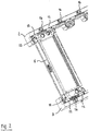
- the module receiving frame 1 which in the embodiment of the FIGS. 1 to 6 Each of these strips 2, 3 is provided with a plurality of mechanisms 4 for fixing a module 5 inserted into the module mounting frame 1 to the module mounting frame 1 and for releasing the module 5 for removal from the module mounting frame 1 arranged.
- FIGS. 1 to 3 are on the upper receiving bar 2 three and on the lower receiving bar 3 two of these mechanisms 4 shown.
- Each mechanism 4 has a latch 6, which is formed integrally with a spring 7 in one piece by a bent piece spring plate 8.
- the front part of this sheet 8 forms the latch 6, a middle part of the spring 7 and a lower part of a foot 9, with which the spring 7 is screwed by positioning pins 10 on one of the receiving strips 2, 3.
- the spring 7 is curved in an S-shape to prevent it from striking the receiving strip 2, 3 in the open position.
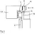
- the latch 6 has a first part, with which it abuts a latch holder 11 and an angled portion with two tabs 12, which, as best in the Figures 5 and 6 can be seen, cooperating with a counter latch 13 of the module 5 interacting to fix the module 5 in the module mounting frame.
- the bolt 6 against the force of the spring 7 from an open position in the FIGS. 1 . 2 . 4 and 5 is shown, in a blocking position, in the Figures 3 and 6 is shown to be moved.
- the force of the spring 7 can move the latch 6 from the blocking position back into the open position, as far as it is not prevented by a latch holder 11 therefrom.
- the tabs of the bolt release the counter latch so that the module 5 can be removed from the module mounting frame 1.
- the bolt holder 11 is designed as an eccentric screw, which has an eccentric head 14, and a shaft, not shown in the figures, which has an external thread, with which the eccentric screw is screwed into a equipped with an internal thread hole of the receiving strip 2, 3.
- the eccentric screw on its head 14 a slot 15 into which a screwdriver can be used to the eccentric screw about its longitudinal axis of the in the FIGS. 1 . 2 . 4 and 5 shown release position in the in the Figures 3 and 6 shown holding position to swing or back from the holding position to the release position. Holding position and release position enclose an angle of 90 ° to each other.
- An embodiment of the mechanism 4 not shown in the figures also has a stop which is arranged parallel to the latch 6 on the opposite side of the latch holder 11 adjacent to the latch holder 11. This works with the in FIG. 2 designated upper edge 16 of the eccentric head 14 and the in FIG. 3 designated upper edge 17 of the eccentric in the manner that the eccentric can not be moved beyond the release position in the movement from the holding position to the release position beyond the release position and during the movement from the release position to the holding position beyond.
- a latching means is provided for releasably locking the latch holder 11 in the holding position and in the release position.
- These consist of a nose which is arranged on the receiving strip 2, 3 facing side of the eccentric head 14 of the latch holder 11, and two corresponding recesses of the surface of the receiving strip 2, 3, which are arranged so that the nose in the holding position of Bar holder 11 can engage in one of these wells and in the release position of the latch holder in the other of the two wells.
- the shank of the bolt holder is formed in this case as a bolt without screw thread and the hole in the receiving bar 2, 3 is a through hole, wherein the bolt passes through the through hole completely and beyond.
- a coil spring is arranged as a detent spring which is firmly on the one hand on this side of the receiving strip and on the other side at the end of the bolt, so that the head 14 by means of the spring against the receiving bar 2, 3rd is biased.
- the spring then causes a resistance that must be overcome in order to move the latch holder 11 out of the holding position or the release position.
- the latch holder 11 is disposed on the side facing away from the module 5 side of the bolt 6.
- the spring 7 of the bolt 6 biases this in its open position and the bolt holder 11 holds in its holding position the bolt 6 in its locked position back.
- the latch holder 11 is disposed between latch 6 and 5 module and the spring 7 biases the latch 6 in the locked position. Then holds the bolt holder 11 in its holding position, the bolt 6 in its open position back.
- the mechanism 4 is arranged on the module frame 1.
- the described mechanism 4 is instead arranged on the module 5 and the counter latch 13 is arranged on a receiving strip 2, 3 of the module receiving frame 5.
- the latch holder 11 is disposed on the module 5, and adjacent to the latch 6, so that the latch holder 11 holds in its holding position the latch 6 against the bias of the spring 7 in its open position.
- a fifth embodiment is identical to the fourth embodiment, with the difference that receiving strip 2, 3 and module 5 are interchanged with respect to the mechanism 4, but latch 6 and spring 7 as in the third embodiment of the module 5, the latch holder 11 but is arranged on the receiving strip 2, 3.
- the in the FIGS. 1 to 6 illustrated module mounting frame 1 is part of a receiver for a mass interconnect.
- the module 5 in this embodiment is an exchangeable module 5 for connecting one or more test instruments by means of the mass interconnect.
- the module 5 is equipped as a connector with connecting elements, not shown in the figure, such as pins and sockets, which can cooperate with corresponding connection elements of an interchangeable test adapter of the mass interconnect.
- FIGS. 1 to 6 illustrated module mounting frame 1 part of an interchangeable test adapter for a mass interconnect.
- the module 5 is a replaceable module for connecting one or more test objects by means of the mass interconnect.
- the module 5 is equipped as a connector with connecting elements, not shown in the figure, such as pins and sockets, which can interact with corresponding connection elements of a receiver of the Mass interconnect.
Landscapes
- Engineering & Computer Science (AREA)
- Physics & Mathematics (AREA)
- General Physics & Mathematics (AREA)
- General Engineering & Computer Science (AREA)
- Microelectronics & Electronic Packaging (AREA)
- Computer Hardware Design (AREA)
- Theoretical Computer Science (AREA)
- Computational Mathematics (AREA)
- Pure & Applied Mathematics (AREA)
- Mathematical Optimization (AREA)
- Mathematical Analysis (AREA)
- Computing Systems (AREA)
- Electromagnetism (AREA)
- Clamps And Clips (AREA)
- Details Of Connecting Devices For Male And Female Coupling (AREA)
- Connection Of Plates (AREA)
- Hooks, Suction Cups, And Attachment By Adhesive Means (AREA)
- Mirrors, Picture Frames, Photograph Stands, And Related Fastening Devices (AREA)
Applications Claiming Priority (1)
| Application Number | Priority Date | Filing Date | Title |
|---|---|---|---|
| DE102017124949.4A DE102017124949A1 (de) | 2017-10-25 | 2017-10-25 | Mechanismus zum Fixieren eines in einen Modulaufnahmerahmen eingesetzten Moduls an dem Modulaufnahmerahmen |
Publications (2)
| Publication Number | Publication Date |
|---|---|
| EP3477315A1 true EP3477315A1 (fr) | 2019-05-01 |
| EP3477315B1 EP3477315B1 (fr) | 2020-10-14 |
Family
ID=63965373
Family Applications (1)
| Application Number | Title | Priority Date | Filing Date |
|---|---|---|---|
| EP18202026.3A Active EP3477315B1 (fr) | 2017-10-25 | 2018-10-23 | Mechanisme |
Country Status (6)
| Country | Link |
|---|---|
| US (1) | US10658783B2 (fr) |
| EP (1) | EP3477315B1 (fr) |
| JP (1) | JP6792601B2 (fr) |
| KR (1) | KR102133647B1 (fr) |
| CN (1) | CN109714927B (fr) |
| DE (1) | DE102017124949A1 (fr) |
Families Citing this family (2)
| Publication number | Priority date | Publication date | Assignee | Title |
|---|---|---|---|---|
| CN112199868B (zh) * | 2020-03-30 | 2024-03-29 | 北京工业大学 | 一种面向结合面密封性能要求的多螺栓拧紧策略优化方法 |
| WO2025160821A1 (fr) * | 2024-01-31 | 2025-08-07 | Siemens Aktiengesellschaft | Module d'expansion, produit modulaire et ordinateur personnel industriel |
Citations (5)
| Publication number | Priority date | Publication date | Assignee | Title |
|---|---|---|---|---|
| NL6611891A (fr) * | 1965-08-24 | 1967-02-27 | ||
| US20010023774A1 (en) * | 1999-12-02 | 2001-09-27 | Kruse Grant J. | System for mounting data communication equipment |
| US20010054891A1 (en) * | 1998-05-11 | 2001-12-27 | Makoto Sagawa | Tray transfer arm, electronic component testing apparatus and tray transfer method |
| US20020137389A1 (en) * | 2001-03-26 | 2002-09-26 | Mac Panel Company | Connection interface system |
| US20130045625A1 (en) * | 2011-08-15 | 2013-02-21 | Philip Anthony Sedberry, JR. | Flexible organizational connect |
Family Cites Families (19)
| Publication number | Priority date | Publication date | Assignee | Title |
|---|---|---|---|---|
| US3040289A (en) | 1958-11-24 | 1962-06-19 | Burndy Corp | Modular electrical connector |
| JPS5123239B2 (fr) | 1973-10-17 | 1976-07-15 | ||
| JPS549360Y2 (fr) * | 1973-10-20 | 1979-05-01 | ||
| US4329005A (en) | 1980-04-01 | 1982-05-11 | Braginetz Paul A | Slide cam mechanism for positioning test adapter in operative relationship with a receiver |
| JPS59127179U (ja) | 1983-02-16 | 1984-08-27 | 斉藤 立身 | プリント基板の検査装置 |
| US4691831A (en) | 1984-06-25 | 1987-09-08 | Takeda Riken Co., Ltd. | IC test equipment |
| US4655530A (en) | 1986-01-16 | 1987-04-07 | Virginia Panel Corporation | Snap-in module for receiver assembly |
| KR960001490Y1 (ko) * | 1992-12-02 | 1996-02-17 | 이종수 | 오비탈샌더의 샌드페이퍼 고정장치 |
| JPH0768777A (ja) | 1993-09-03 | 1995-03-14 | Canon Inc | インクジェット記録装置 |
| US5562458A (en) | 1994-12-23 | 1996-10-08 | The Whitaker Corporation | Interface engagement and locking system |
| US6147873A (en) * | 1998-01-22 | 2000-11-14 | Huang; Chin-Chung | CPU module mounting rack |
| FR2864355A1 (fr) * | 2003-12-19 | 2005-06-24 | Framatome Connectors Int | Dispositif de verrouillage d'un module de connecteur dans un porte-module |
| US7091415B2 (en) * | 2004-08-16 | 2006-08-15 | Virginia Panel Corporation | Low profile mass interconnect device |
| US20070064385A1 (en) * | 2005-09-19 | 2007-03-22 | Paul Dieter G | Receiving frame having removable computer drive carrier and fan modules |
| CN201174086Y (zh) | 2008-02-21 | 2008-12-31 | 鸿富锦精密工业(深圳)有限公司 | 数据存储器固定装置 |
| CN202196720U (zh) | 2011-08-16 | 2012-04-18 | 上海精翊电器有限公司 | 一种用于低压断路器的多重锁定装置 |
| JP6038086B2 (ja) | 2014-09-03 | 2016-12-07 | 本田技研工業株式会社 | 鞍乗型車両のシート支持構造 |
| CN105587197A (zh) * | 2016-02-29 | 2016-05-18 | 伍志勇 | 一种家具上翻门的集成优化机构 |
| CN206193636U (zh) | 2016-08-25 | 2017-05-24 | 美超微电脑股份有限公司 | 服务器硬盘载盘组件 |
-
2017
- 2017-10-25 DE DE102017124949.4A patent/DE102017124949A1/de not_active Withdrawn
-
2018
- 2018-10-23 JP JP2018199222A patent/JP6792601B2/ja active Active
- 2018-10-23 EP EP18202026.3A patent/EP3477315B1/fr active Active
- 2018-10-24 KR KR1020180127366A patent/KR102133647B1/ko active Active
- 2018-10-24 US US16/168,909 patent/US10658783B2/en active Active
- 2018-10-25 CN CN201811254499.3A patent/CN109714927B/zh active Active
Patent Citations (5)
| Publication number | Priority date | Publication date | Assignee | Title |
|---|---|---|---|---|
| NL6611891A (fr) * | 1965-08-24 | 1967-02-27 | ||
| US20010054891A1 (en) * | 1998-05-11 | 2001-12-27 | Makoto Sagawa | Tray transfer arm, electronic component testing apparatus and tray transfer method |
| US20010023774A1 (en) * | 1999-12-02 | 2001-09-27 | Kruse Grant J. | System for mounting data communication equipment |
| US20020137389A1 (en) * | 2001-03-26 | 2002-09-26 | Mac Panel Company | Connection interface system |
| US20130045625A1 (en) * | 2011-08-15 | 2013-02-21 | Philip Anthony Sedberry, JR. | Flexible organizational connect |
Also Published As
| Publication number | Publication date |
|---|---|
| JP6792601B2 (ja) | 2020-11-25 |
| US20190123477A1 (en) | 2019-04-25 |
| CN109714927A (zh) | 2019-05-03 |
| KR20190046672A (ko) | 2019-05-07 |
| JP2019090529A (ja) | 2019-06-13 |
| US10658783B2 (en) | 2020-05-19 |
| DE102017124949A1 (de) | 2019-04-25 |
| CN109714927B (zh) | 2021-04-30 |
| EP3477315B1 (fr) | 2020-10-14 |
| KR102133647B1 (ko) | 2020-07-14 |
Similar Documents
| Publication | Publication Date | Title |
|---|---|---|
| DE69109817T2 (de) | Blockierbares Knochenplattensystem. | |
| DE202007014290U1 (de) | Lagerungsschuh für eine Stichsäge | |
| DE102010007675B3 (de) | Schlitzgreifer | |
| EP3477315B1 (fr) | Mechanisme | |
| EP3179199A1 (fr) | Dispositif de fixation d'un accessoire sur une arme | |
| EP3808997A1 (fr) | Dispositif goujon | |
| EP1328321A1 (fr) | Appareil de sauvetage a longueur de bras reglable | |
| EP0622511A2 (fr) | Dispositif déflecteur pour panneau oscillo-battant | |
| DE3310474C2 (fr) | ||
| EP2243596A1 (fr) | Clé universelle | |
| DE3720790C2 (de) | Handbetätigbare Verriegelungsanordnung zum Befestigen eines beweglichen Teiles an einem festen Teil | |
| EP2031156A2 (fr) | Mécanisme de rappel pour une poignée de porte | |
| DE3151668A1 (de) | "kupplungsvorrichtung fuer eine fotografische blitzeinrichtung" | |
| DE69616011T2 (de) | Falle für reversibeles Schloss und reversibeles Schloss welches eine solche Falle enthält | |
| EP0673085A2 (fr) | Système de verouillage pour un boîtier de prise | |
| DE202015002795U1 (de) | Verriegelungsvorrichtung einer Steckbaugruppe | |
| EP1662627A1 (fr) | Dispositif pour la fixation détachable d'un boîtier d'appareil à un rail profilé | |
| EP0489244A1 (fr) | Dispositif pour le blocage d'une porte à deux vantails | |
| DE9113084U1 (de) | Einrichtung zur Sicherung eines Computers | |
| CH646016A5 (en) | Switchboard apparatus having an attachment element | |
| DE102018114585A1 (de) | Schubkasten und Verfahren zur Montage einer Rückwand an einer Seitenzarge eines Schubkastens | |
| DE202006008013U1 (de) | Ausfahrbare Verriegelungsvorrichtung für eine Gleitschiene für Schubladen | |
| DE202022106545U1 (de) | Nummernschild-Befestigungs-Vorrichtung | |
| DE2511002C2 (de) | Vorrichtung zum Befestigen von Gerätekoftern in Gestellen | |
| DE1703175A1 (de) | Schloss mit austauschbarem Sperrglied |
Legal Events
| Date | Code | Title | Description |
|---|---|---|---|
| PUAI | Public reference made under article 153(3) epc to a published international application that has entered the european phase |
Free format text: ORIGINAL CODE: 0009012 |
|
| STAA | Information on the status of an ep patent application or granted ep patent |
Free format text: STATUS: THE APPLICATION HAS BEEN PUBLISHED |
|
| AK | Designated contracting states |
Kind code of ref document: A1 Designated state(s): AL AT BE BG CH CY CZ DE DK EE ES FI FR GB GR HR HU IE IS IT LI LT LU LV MC MK MT NL NO PL PT RO RS SE SI SK SM TR |
|
| AX | Request for extension of the european patent |
Extension state: BA ME |
|
| STAA | Information on the status of an ep patent application or granted ep patent |
Free format text: STATUS: REQUEST FOR EXAMINATION WAS MADE |
|
| 17P | Request for examination filed |
Effective date: 20190625 |
|
| RBV | Designated contracting states (corrected) |
Designated state(s): AL AT BE BG CH CY CZ DE DK EE ES FI FR GB GR HR HU IE IS IT LI LT LU LV MC MK MT NL NO PL PT RO RS SE SI SK SM TR |
|
| GRAP | Despatch of communication of intention to grant a patent |
Free format text: ORIGINAL CODE: EPIDOSNIGR1 |
|
| STAA | Information on the status of an ep patent application or granted ep patent |
Free format text: STATUS: GRANT OF PATENT IS INTENDED |
|
| INTG | Intention to grant announced |
Effective date: 20200416 |
|
| GRAS | Grant fee paid |
Free format text: ORIGINAL CODE: EPIDOSNIGR3 |
|
| GRAA | (expected) grant |
Free format text: ORIGINAL CODE: 0009210 |
|
| STAA | Information on the status of an ep patent application or granted ep patent |
Free format text: STATUS: THE PATENT HAS BEEN GRANTED |
|
| RAP1 | Party data changed (applicant data changed or rights of an application transferred) |
Owner name: ODU GMBH & CO. KG |
|
| AK | Designated contracting states |
Kind code of ref document: B1 Designated state(s): AL AT BE BG CH CY CZ DE DK EE ES FI FR GB GR HR HU IE IS IT LI LT LU LV MC MK MT NL NO PL PT RO RS SE SI SK SM TR |
|
| REG | Reference to a national code |
Ref country code: GB Ref legal event code: FG4D Free format text: NOT ENGLISH |
|
| REG | Reference to a national code |
Ref country code: AT Ref legal event code: REF Ref document number: 1324093 Country of ref document: AT Kind code of ref document: T Effective date: 20201015 Ref country code: CH Ref legal event code: EP |
|
| REG | Reference to a national code |
Ref country code: DE Ref legal event code: R096 Ref document number: 502018002732 Country of ref document: DE |
|
| REG | Reference to a national code |
Ref country code: IE Ref legal event code: FG4D Free format text: LANGUAGE OF EP DOCUMENT: GERMAN |
|
| REG | Reference to a national code |
Ref country code: NL Ref legal event code: MP Effective date: 20201014 |
|
| PG25 | Lapsed in a contracting state [announced via postgrant information from national office to epo] |
Ref country code: RS Free format text: LAPSE BECAUSE OF FAILURE TO SUBMIT A TRANSLATION OF THE DESCRIPTION OR TO PAY THE FEE WITHIN THE PRESCRIBED TIME-LIMIT Effective date: 20201014 Ref country code: PT Free format text: LAPSE BECAUSE OF FAILURE TO SUBMIT A TRANSLATION OF THE DESCRIPTION OR TO PAY THE FEE WITHIN THE PRESCRIBED TIME-LIMIT Effective date: 20210215 Ref country code: FI Free format text: LAPSE BECAUSE OF FAILURE TO SUBMIT A TRANSLATION OF THE DESCRIPTION OR TO PAY THE FEE WITHIN THE PRESCRIBED TIME-LIMIT Effective date: 20201014 Ref country code: GR Free format text: LAPSE BECAUSE OF FAILURE TO SUBMIT A TRANSLATION OF THE DESCRIPTION OR TO PAY THE FEE WITHIN THE PRESCRIBED TIME-LIMIT Effective date: 20210115 Ref country code: NO Free format text: LAPSE BECAUSE OF FAILURE TO SUBMIT A TRANSLATION OF THE DESCRIPTION OR TO PAY THE FEE WITHIN THE PRESCRIBED TIME-LIMIT Effective date: 20210114 |
|
| REG | Reference to a national code |
Ref country code: LT Ref legal event code: MG4D |
|
| PG25 | Lapsed in a contracting state [announced via postgrant information from national office to epo] |
Ref country code: SE Free format text: LAPSE BECAUSE OF FAILURE TO SUBMIT A TRANSLATION OF THE DESCRIPTION OR TO PAY THE FEE WITHIN THE PRESCRIBED TIME-LIMIT Effective date: 20201014 Ref country code: LV Free format text: LAPSE BECAUSE OF FAILURE TO SUBMIT A TRANSLATION OF THE DESCRIPTION OR TO PAY THE FEE WITHIN THE PRESCRIBED TIME-LIMIT Effective date: 20201014 Ref country code: PL Free format text: LAPSE BECAUSE OF FAILURE TO SUBMIT A TRANSLATION OF THE DESCRIPTION OR TO PAY THE FEE WITHIN THE PRESCRIBED TIME-LIMIT Effective date: 20201014 Ref country code: IS Free format text: LAPSE BECAUSE OF FAILURE TO SUBMIT A TRANSLATION OF THE DESCRIPTION OR TO PAY THE FEE WITHIN THE PRESCRIBED TIME-LIMIT Effective date: 20210214 Ref country code: BG Free format text: LAPSE BECAUSE OF FAILURE TO SUBMIT A TRANSLATION OF THE DESCRIPTION OR TO PAY THE FEE WITHIN THE PRESCRIBED TIME-LIMIT Effective date: 20210114 Ref country code: ES Free format text: LAPSE BECAUSE OF FAILURE TO SUBMIT A TRANSLATION OF THE DESCRIPTION OR TO PAY THE FEE WITHIN THE PRESCRIBED TIME-LIMIT Effective date: 20201014 |
|
| PG25 | Lapsed in a contracting state [announced via postgrant information from national office to epo] |
Ref country code: LU Free format text: LAPSE BECAUSE OF NON-PAYMENT OF DUE FEES Effective date: 20201023 Ref country code: HR Free format text: LAPSE BECAUSE OF FAILURE TO SUBMIT A TRANSLATION OF THE DESCRIPTION OR TO PAY THE FEE WITHIN THE PRESCRIBED TIME-LIMIT Effective date: 20201014 Ref country code: NL Free format text: LAPSE BECAUSE OF FAILURE TO SUBMIT A TRANSLATION OF THE DESCRIPTION OR TO PAY THE FEE WITHIN THE PRESCRIBED TIME-LIMIT Effective date: 20201014 |
|
| REG | Reference to a national code |
Ref country code: DE Ref legal event code: R097 Ref document number: 502018002732 Country of ref document: DE Ref country code: BE Ref legal event code: MM Effective date: 20201031 |
|
| PG25 | Lapsed in a contracting state [announced via postgrant information from national office to epo] |
Ref country code: SK Free format text: LAPSE BECAUSE OF FAILURE TO SUBMIT A TRANSLATION OF THE DESCRIPTION OR TO PAY THE FEE WITHIN THE PRESCRIBED TIME-LIMIT Effective date: 20201014 Ref country code: SM Free format text: LAPSE BECAUSE OF FAILURE TO SUBMIT A TRANSLATION OF THE DESCRIPTION OR TO PAY THE FEE WITHIN THE PRESCRIBED TIME-LIMIT Effective date: 20201014 Ref country code: CZ Free format text: LAPSE BECAUSE OF FAILURE TO SUBMIT A TRANSLATION OF THE DESCRIPTION OR TO PAY THE FEE WITHIN THE PRESCRIBED TIME-LIMIT Effective date: 20201014 Ref country code: EE Free format text: LAPSE BECAUSE OF FAILURE TO SUBMIT A TRANSLATION OF THE DESCRIPTION OR TO PAY THE FEE WITHIN THE PRESCRIBED TIME-LIMIT Effective date: 20201014 Ref country code: RO Free format text: LAPSE BECAUSE OF FAILURE TO SUBMIT A TRANSLATION OF THE DESCRIPTION OR TO PAY THE FEE WITHIN THE PRESCRIBED TIME-LIMIT Effective date: 20201014 Ref country code: LT Free format text: LAPSE BECAUSE OF FAILURE TO SUBMIT A TRANSLATION OF THE DESCRIPTION OR TO PAY THE FEE WITHIN THE PRESCRIBED TIME-LIMIT Effective date: 20201014 Ref country code: MC Free format text: LAPSE BECAUSE OF FAILURE TO SUBMIT A TRANSLATION OF THE DESCRIPTION OR TO PAY THE FEE WITHIN THE PRESCRIBED TIME-LIMIT Effective date: 20201014 |
|
| PLBE | No opposition filed within time limit |
Free format text: ORIGINAL CODE: 0009261 |
|
| STAA | Information on the status of an ep patent application or granted ep patent |
Free format text: STATUS: NO OPPOSITION FILED WITHIN TIME LIMIT |
|
| PG25 | Lapsed in a contracting state [announced via postgrant information from national office to epo] |
Ref country code: BE Free format text: LAPSE BECAUSE OF NON-PAYMENT OF DUE FEES Effective date: 20201031 Ref country code: DK Free format text: LAPSE BECAUSE OF FAILURE TO SUBMIT A TRANSLATION OF THE DESCRIPTION OR TO PAY THE FEE WITHIN THE PRESCRIBED TIME-LIMIT Effective date: 20201014 |
|
| 26N | No opposition filed |
Effective date: 20210715 |
|
| PG25 | Lapsed in a contracting state [announced via postgrant information from national office to epo] |
Ref country code: IE Free format text: LAPSE BECAUSE OF NON-PAYMENT OF DUE FEES Effective date: 20201023 Ref country code: AL Free format text: LAPSE BECAUSE OF FAILURE TO SUBMIT A TRANSLATION OF THE DESCRIPTION OR TO PAY THE FEE WITHIN THE PRESCRIBED TIME-LIMIT Effective date: 20201014 |
|
| PG25 | Lapsed in a contracting state [announced via postgrant information from national office to epo] |
Ref country code: SI Free format text: LAPSE BECAUSE OF FAILURE TO SUBMIT A TRANSLATION OF THE DESCRIPTION OR TO PAY THE FEE WITHIN THE PRESCRIBED TIME-LIMIT Effective date: 20201014 |
|
| REG | Reference to a national code |
Ref country code: CH Ref legal event code: PL |
|
| PG25 | Lapsed in a contracting state [announced via postgrant information from national office to epo] |
Ref country code: IS Free format text: LAPSE BECAUSE OF FAILURE TO SUBMIT A TRANSLATION OF THE DESCRIPTION OR TO PAY THE FEE WITHIN THE PRESCRIBED TIME-LIMIT Effective date: 20210214 Ref country code: TR Free format text: LAPSE BECAUSE OF FAILURE TO SUBMIT A TRANSLATION OF THE DESCRIPTION OR TO PAY THE FEE WITHIN THE PRESCRIBED TIME-LIMIT Effective date: 20201014 Ref country code: MT Free format text: LAPSE BECAUSE OF FAILURE TO SUBMIT A TRANSLATION OF THE DESCRIPTION OR TO PAY THE FEE WITHIN THE PRESCRIBED TIME-LIMIT Effective date: 20201014 Ref country code: CY Free format text: LAPSE BECAUSE OF FAILURE TO SUBMIT A TRANSLATION OF THE DESCRIPTION OR TO PAY THE FEE WITHIN THE PRESCRIBED TIME-LIMIT Effective date: 20201014 |
|
| PG25 | Lapsed in a contracting state [announced via postgrant information from national office to epo] |
Ref country code: MK Free format text: LAPSE BECAUSE OF FAILURE TO SUBMIT A TRANSLATION OF THE DESCRIPTION OR TO PAY THE FEE WITHIN THE PRESCRIBED TIME-LIMIT Effective date: 20201014 |
|
| PG25 | Lapsed in a contracting state [announced via postgrant information from national office to epo] |
Ref country code: LI Free format text: LAPSE BECAUSE OF NON-PAYMENT OF DUE FEES Effective date: 20211031 Ref country code: CH Free format text: LAPSE BECAUSE OF NON-PAYMENT OF DUE FEES Effective date: 20211031 |
|
| REG | Reference to a national code |
Ref country code: AT Ref legal event code: MM01 Ref document number: 1324093 Country of ref document: AT Kind code of ref document: T Effective date: 20231023 |
|
| PG25 | Lapsed in a contracting state [announced via postgrant information from national office to epo] |
Ref country code: AT Free format text: LAPSE BECAUSE OF NON-PAYMENT OF DUE FEES Effective date: 20231023 |
|
| PG25 | Lapsed in a contracting state [announced via postgrant information from national office to epo] |
Ref country code: AT Free format text: LAPSE BECAUSE OF NON-PAYMENT OF DUE FEES Effective date: 20231023 |
|
| PGFP | Annual fee paid to national office [announced via postgrant information from national office to epo] |
Ref country code: DE Payment date: 20251020 Year of fee payment: 8 |
|
| PGFP | Annual fee paid to national office [announced via postgrant information from national office to epo] |
Ref country code: GB Payment date: 20251024 Year of fee payment: 8 |
|
| PGFP | Annual fee paid to national office [announced via postgrant information from national office to epo] |
Ref country code: IT Payment date: 20251031 Year of fee payment: 8 |
|
| PGFP | Annual fee paid to national office [announced via postgrant information from national office to epo] |
Ref country code: FR Payment date: 20251022 Year of fee payment: 8 |
|
| PGFP | Annual fee paid to national office [announced via postgrant information from national office to epo] |
Ref country code: AT Payment date: 20260410 Year of fee payment: 5 |