EP3477426A1 - Système informatique, dispositif client et afficheur - Google Patents
Système informatique, dispositif client et afficheur Download PDFInfo
- Publication number
- EP3477426A1 EP3477426A1 EP18153267.2A EP18153267A EP3477426A1 EP 3477426 A1 EP3477426 A1 EP 3477426A1 EP 18153267 A EP18153267 A EP 18153267A EP 3477426 A1 EP3477426 A1 EP 3477426A1
- Authority
- EP
- European Patent Office
- Prior art keywords
- display device
- client device
- state
- interface
- client
- Prior art date
- Legal status (The legal status is an assumption and is not a legal conclusion. Google has not performed a legal analysis and makes no representation as to the accuracy of the status listed.)
- Granted
Links
Images
Classifications
-
- G—PHYSICS
- G06—COMPUTING OR CALCULATING; COUNTING
- G06F—ELECTRIC DIGITAL DATA PROCESSING
- G06F1/00—Details not covered by groups G06F3/00 - G06F13/00 and G06F21/00
- G06F1/26—Power supply means, e.g. regulation thereof
- G06F1/266—Arrangements to supply power to external peripherals either directly from the computer or under computer control, e.g. supply of power through the communication port, computer controlled power-strips
-
- G—PHYSICS
- G06—COMPUTING OR CALCULATING; COUNTING
- G06F—ELECTRIC DIGITAL DATA PROCESSING
- G06F1/00—Details not covered by groups G06F3/00 - G06F13/00 and G06F21/00
- G06F1/26—Power supply means, e.g. regulation thereof
- G06F1/32—Means for saving power
- G06F1/3203—Power management, i.e. event-based initiation of a power-saving mode
- G06F1/3206—Monitoring of events, devices or parameters that trigger a change in power modality
- G06F1/3215—Monitoring of peripheral devices
- G06F1/3218—Monitoring of peripheral devices of display devices
-
- G—PHYSICS
- G06—COMPUTING OR CALCULATING; COUNTING
- G06F—ELECTRIC DIGITAL DATA PROCESSING
- G06F13/00—Interconnection of, or transfer of information or other signals between, memories, input/output devices or central processing units
- G06F13/38—Information transfer, e.g. on bus
- G06F13/42—Bus transfer protocol, e.g. handshake; Synchronisation
- G06F13/4282—Bus transfer protocol, e.g. handshake; Synchronisation on a serial bus, e.g. I2C bus, SPI bus
-
- H—ELECTRICITY
- H04—ELECTRIC COMMUNICATION TECHNIQUE
- H04L—TRANSMISSION OF DIGITAL INFORMATION, e.g. TELEGRAPHIC COMMUNICATION
- H04L12/00—Data switching networks
- H04L12/02—Details
- H04L12/10—Current supply arrangements
Definitions
- the present invention relates to a computer system comprising a client device, for example a thin client PC, and a display device, for example a flat screen display device, operationally connected to the client device.
- a client device for example a thin client PC
- a display device for example a flat screen display device
- the present application relates to continuous power delivery from a display device to a client computing device.
- a typical workplace is equipped with a client computing device such as a thin client, a personal computer (PC), a notebook, a tablet, a smart phone, etc. and a display device. Both devices are connected to each other with several cables and by respective power cables to a mains power supply.
- client computing device such as a thin client, a personal computer (PC), a notebook, a tablet, a smart phone, etc.
- display device Both devices are connected to each other with several cables and by respective power cables to a mains power supply.
- USB Type-C in principle, it is possible to minimize the cabling between a display device and a notebook by using a single cable for data, video signal and also for power delivery from the display device to the client device.
- powering a client device by a display device is only possible if the display device is in an active state.
- the display device If the display device goes to a power-saving mode, for example after a certain period of absence of the user, or is turned off by manually by pressing the display's power button, the display device will disable its main components and therefore also disconnect the client device, including the provision of power to the client device.
- the client device is a PC or Thin Client, or generally a non-mobile device not equipped with a battery, then data of the client device could get lost because of a so-called "AC fail" condition, that is to say an unexpected shutdown of the client device. This could even happen with battery-equipped mobile devices, if they stay unpowered for a long period of time in a standby mode, by emptying the battery of the mobile device.
- Such docking type displays which are equipped with a USB Type-C interface and capable of implementing a power delivery technology, are defined and specified as charging devices for mobiles, tablets and notebooks only. However, they do not support an uninterruptable power delivery to a client device for seamless operation in all power state conditions.
- a computer system comprising a client device and a display device operationally connected to the client device.
- the display device is configured to provide the client device with an operating energy
- the display device is further configured to detect a type of the client device, and, in case the client device belongs to a predefined group of client devices, to provide the display device with an operating energy even if the display device enters an energy-saving mode or is switched off.
- the client device for example a small form factor PC, thin client or notebook
- the client device will be continuously powered by the display device if it is detected to belong to a predetermined group of devices by the display device, for example as a thin client device and/or a Fujitsu device, independently from the current client device's and display device's power state.
- a handshaking process of the "power delivery" capable devices when connecting the client device to the display device, a handshaking process of the "power delivery" capable devices will be initiated to define a mutual power delivery level, for example 60 Watt using a provided operating voltage of 20 Volt at a current of 3 Ampere from the display device.
- the display device will determine the client device's vendor ID (VID), in some context also referred to a standard or vendor ID (SVID), and/or product ID (PID) by using so-called vendor-defined messages (VDM) specified in the power delivery specification of the respective interface.
- VIP vendor ID
- SVID standard or vendor ID
- PID product ID
- VDM vendor-defined messages
- the display device determines a specific SVID or VID/PID combination, indicating that it is a Fujitsu device, then the display device will not go to a conventional sleep state, but rather it will keep the power delivery component alive to ensure continuous power delivery to the connected Fujitsu client device.
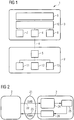
- FIG. 1 shows an exemplary embodiment of a computer system 1 according to the present invention.
- the computer system 1 comprises a client device 2 such as a mini PC or a thin client device, and a display device 3 such as a flat screen LCD display device.
- the client device 2 and the display device 3 are connected by means of a data connection 4.
- the client device 2 and the display device 3 may be connected by means of a full featured USB Type-C cable, comprising a plurality of wires for enabling USB data and control paths, transferring video data using a display port connection and for providing power from the display device 3 to the client device 2 by means of a power delivery standard.
- the data connection 4 is attached to the client device 2 by means of a first interface 5 and to the display device 3 by means of a second interface 6.
- the client device 2 is connected to the display device 3 using only a single cable, which is used to supply the client device 2 with an operating energy provided by the display device.
- the display device 3 comprises a power button 7, a status LED 8, a display screen 9 and control circuitry 10.
- the client device 2 comprises a processor 11 for executing user programs as well as an operating system and firmware components, a graphics component 12 for generating graphical output to be displayed by the display screen 9 and a power management subsystem 13 to control the operating state of the client device 2.
- the graphics component 12 and the power management subsystem 13 may be implemented in hardware or in software or a combination thereof.
- the power management subsystem 13 may comprise parts of a system firmware for ACPI control, such as a BIOS, parts of an operating system and hardware components used to activate or deactivate individual components or subcomponents of the client device 2.
- power control commands received by the display device 3 via the power button 7 may be forwarded by the control circuitry 10 via the data connection 4 to the power management subsystem 13 of the client device 2.
- the power state of the client device 2 may be communicated via the data connection 4 to the control circuitry 10 of the display device 3 and indicated using the status LED 8.
- a so called "all-in-one mode" of the display device 3 in combination with a client computing device 2 may be implemented.
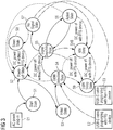
- Figure 2 shows a block diagram of internal components of a display device 3 connected to a client device 2 according to an embodiment of the present invention. Specifically, Figure 2 shows a schematic diagram of the control paths within the display device 3 and data and control paths between the client device 2 and the display device 3. The block diagram of Figure 2 shows, in particular, those parts of a chip set of a display device 3 that are responsible for power delivery to the client device 2.
- the client device 2, acting as a source for a display signal, and the display device 3, acting as a sink for the display signal, are connected by a USB interface 21, for example a USB Type-C data cable.
- the USB interface 21 comprises a control path 22 for exchanging control and configuration signals between the client device 2 and the display device 3, and a power delivery path 23 for supplying an operating power from the display device 3 to the client device 2.
- the control path 22 ends at a power delivery controller 24.
- the display device 3 further comprises a scaler 25 for scaling a display signal provided by the client device 2 and a display screen (not shown in Figure 2 ) for displaying the display signal to a user of the client device 2.
- the scaler 25 represents the main processing unit inside the display device 3.
- the scaler 25 and the power delivery controller 24 are connected by a control interface, for example an I2C bus.
- the scaler 25 will receive an internal control signal from the power delivery controller 24 based on control and configuration data of the client device 2 received by the power delivery controller 24.
- the power delivery controller 24 may signal whether a device requiring uninterrupted power delivery has been connected to the display device.
- the display device 3 further comprise a power circuit 26 connected to the scaler 25.
- the scaler 25 can instruct the power circuit 26 to start or stop a power delivery to the client device 2. According to the described embodiment, this decision is made based on the information received from the power delivery controller 24 during an initial handshake procedure and the operating state of the monitor determined by the scaler 25 itself.
- the power delivery controller 24 and the power circuit 26 may be integrated into an internal USB hub or another power delivery circuit of the display device (not shown).
- a display device 3 When a display device 3 is connected to an operating power (event E1), the display device 3 first enters a "start state" (state S1).
- a LCD monitor with an internal power supply unit can be plugged into a mains socket using an AC mains cable.
- an external power supply for the display device may be connected with a mains socket and the display device using corresponding AC and/or DC plug connectors.
- the display device After the supplied operating voltage has stabilized, the display device changes into a so-called "power-off state" (state S2).
- the supply voltage provided to the monitor is provided at least to power management circuitry of the display device 3, e.g. parts of the control circuitry 10, to keep those parts necessary for activating the display device 3 alive.
- power management circuitry of the display device e.g. parts of the control circuitry 10
- many other components of the display device 3, such as a display screen 9, will not be operational in state S2 of the display device 3.
- the display device 3 After the user presses a power button 7 to switch the display device 3 on, the display device 3 will first change into an "initial state" (state S3), in which internal control components of the display device 3 are initialized.
- a scaler 25 will initialize scaler registers and panel parameters for the display device 3.
- the display device 3 enters a "cable detection state" (state S4).
- state S4 the display device 3 determines whether it is connected to a client device 2.
- the display device detects whether a USB Type-C cable is connected to a corresponding plug connecter of the display device 3.
- Different types of connections can be detected.
- a USB connection to a compatible client device e.g. a client device of a given manufacturer such as Fujitsu Technology or Fujitsu Limited
- a USB connection to an incompatible client device e.g. a client device of another manufacturer, can be detected (event E3).
- the detection result is established and stored within a scaler register for later use as detailed below.
- the display device 3 enters a "signal search state" (state S5).
- the monitor tries to find a valid signal and prepares the display device 3 to output a found signal.
- the display device 3 may also identify which of a plurality of possible signal sources is connected to the display device 3.
- the display device 3 will change into an “active state” (state S6) until the provision of the video signal is stopped or the display device 3 is switched off. If no such active video signal is detected, the display device 3 will change into a "no signal state” (state S7).
- the display device 3 After a predetermined time interval in the state S7, the display device 3 will change into a "sleep state" (state S8) in case an incompatible client device 2 was detected in state S4, wherein unused components of the display device 3 are deactivated or switched into a low power consumption status.
- a backlight unit of the display screen 9 may be dimmed or switched off completely.
- a display panel of the display screen 9 may be deactivated in state S8.
- the status LED 8 may be powered to indicate the state S8.
- the scaler 25 will be at least partially powered to detect the provision of an active signal from the client device at a later stage.
- the display device 3 When the user switches the display device 3 manually off the power button 7 in state S8, the display device 3 will enter the state S2 again, and the status LED 8 will be switched off.
- the display device 3 may also change into the state S2, if an incompatible client device 2 was detected in state S4 and the power button 7 of the display device is pressed by the user thereafter.
- Power management circuitry of conventional display devices tries to deactivate as many internal components as possible, at least during a switched-off mode and an energy-saving mode, in order to reduce a power consumption.
- external interfaces such as a USB interface provided by a conventional display device are deactivated.
- the display device is used to supply an operating energy to a client system, for example via a full-featured USB Type-C interface and/or a USB power delivery function, this may result in an unintended disruption of the operating power of the client system.
- control circuitry 10 of the display device 3 implements two additional states as also indicated in Figure 3 .
- the client device 2 and the display device 3 are connected via a so-called fully featured USB Type-C connection.
- the client device 2 and the display device 3 implement the so-called Power Delivery Specification according to the USB Specification 3.1.
- the client device 2 may request an appropriate amount of power to be delivered by the display device 3.
- the client device 2 could request a supply voltage of 20 V and a supply current of 3 A, corresponding to an operating power of 60 W for the client device 2.
- the client device 2 may also transmit one or multiple vendor-defined messages (VDM) as defined in the Power Delivery Specification 2.0 or 3.0.
- VDM vendor-defined messages
- Such messages can be defined by individual vendors and be used to communicate information outside the scope of predefined parameters of the respective standard.
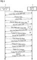
- the parameters exchanged between the client device 2 and the display device 3 are shown in the handshaking flow chart of Figure 4 .
- the client device 2 discovers a list of standard or vendor identifier (SVID) supported by the display device 3. Based on the so-called USB Type-C AltMode Standard, only the client device can ask for the SVID from the display device.
- SVID standard or vendor identifier
- the first four steps shown in Figure 4 are following a standard request.
- step 41 the client device 2 additionally requests to discover modes with a predetermined SVID, corresponding to Fujitsu devices. If the display device supports the so-called "all-in-one mode", this request is acknowledged in the step 42. Subsequently, the client device 2 requests to enter this mode in step 43, which is again acknowledged in a corresponding step 44. Together, the steps 41 to 44 implement the all-in-one mode detection and selection.
- client devices 2 of a given vendor for example Fujitsu Technology Solutions GmbH or Fujitsu Ltd.
- this information may be sufficient to identify that the client device 2 shall be provided with an operating energy even in the case that the display device 3 enters an energy-saving state.
- only certain types of a given vendor are supported by the display device 3.
- only thin client devices of that vendor may be supported for seamless power delivery.
- only a valid combination of a SVID and a PID provided by the client device 2 will be compared with a corresponding list of supported devices by the display device 3.
- a PID alone may also be used for detection.
- the display device 3 In case a compatible client device 2 is successfully detected in the state S4, but no active video signal is provided in the state S5 by the detected client device 2, the display device 3 will enter a "light sleep state” (state S9).
- the light sleep state S9 essentially corresponds to the sleep state S8 with the exception that the display device 3 will keep providing a supply power to the attached client device 2. Together, the two sleep states S8 and S9 provide an enhanced energy saving mode for the display device 3.
- the display device 3 will change into an "idle state" (state S10) instead of the power-off state S2.
- the idle state S10 corresponds essentially to the power-off state S2, except that the display device 3 will keep providing a supply power via the interface 6 to the display device 3.
- the power-off state S2 and the idle state S10 provide an enhanced switched-off mode for the display device 3.
- State Description S1 Start State Monitor with AC power-in.
- S2 Power-off State Monitor with AC power to keep the electrical part alive, but not in working status due to power off by DC power key.
- S3 Initial State Initialized the scaler registers and panel parameters.
- S4 Cable detection State Detecting if there is a USB-C cable inserted into monitor
- S5 Signal Search State Monitor tries to find out the valid signal and prepare the signal output. If there is no valid signal found, then it will go for the next proper state instead.
- S6 Active State Monitor in normal working status.
- S7 No Signal State No active signal source is alive.
- S8 Sleep State Monitor in low power consumption status with turning off LCD panel and other unused electronic components.
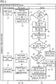
- a USB cable is plugged into the client device 2 and the display device 3 to establish a USB Type-C connection.
- This action is detected by parts of a power delivery circuit, e.g. a power delivery controller 24, in a step 52, which therefore initializes a power delivery handshaking protocol.
- a standard or vendor ID (SVID) of the client device 2 is received by the power delivery circuit of the display device 3.
- SVID standard or vendor ID
- the power delivery circuit Upon successful completion of the handshake procedure, the power delivery circuit will send an interrupt signal to a scaler 25 to signal that this information has been received in step 53. Thus, in a subsequent step 54, the scaler 25 will compare the received SVID with a predefined pattern. In the example shown in Figure 5 , the SVID is compared with a fixed hexadecimal value of 0BF8 indicating a display devices 2 requesting a continuous power delivery.
- a register value of the scaler 25 will be set to indicate that a compatible client device 2 is connected to the display device 3.
- the corresponding scaler register is reset to indicate that the display system 3 is operating in a conventional operating mode, for example an operating mode as defined by the Energy Star Display Specifications Version 7.
- the method proceeds to step 57, wherein the monitor state is continuously checked by means of the state machine as detailed with regard to Figure 3 .
- step 58 the scaler 25 checks if the control register is set. If said register is set, in step 60 the scaler 25 instructs a power delivery part of the power delivery circuit, e.g. the power circuit 26, to keep the power supply for the client device 2 activated based on a power delivery controller feedback received during the initial handshake. Accordingly, in step 61, the client device 2 is kept alive, i.e. is supplied with the previously requested supply power. Moreover, in step 62, the scaler 25 goes to either the light sleep state S9 or to the idle state S10 based on the triggering event detected in step 58.
- a power delivery part of the power delivery circuit e.g. the power circuit 26
- step 59 if it is established, in step 59, that the corresponding scaler register was not set, the scaler 25 turns off the power supply to an internal USB hub and/or the power delivery part of the power delivery circuit in step 63. Accordingly, the power delivery circuit cuts off the power supply to the external client device 2 in a step 64. This leads to a controlled or uncontrolled shutdown of the device 2 in step 65. Moreover, in step 66, the scaler 25 of the display device 3 will either change into the sleep state S8 or the power-off state S2 according to the triggering event detected in step 58.
- step 67 the display device 3 will enter into or remain in the signal search state S5.
- the above steps make sure that the power delivery function of the display device 3 is kept working even when the display device 3 itself enters an energy saving state, such as the internal, light sleep state S9 or a power-off/idle state S10, so that the external client device 2, especially a thin client PC, can be kept alive. This avoids the unexpected shutdown scenario for an end user of the client device 2.
- an energy saving state such as the internal, light sleep state S9 or a power-off/idle state S10
- the method makes sure that the display device 3 meets the Energy Star 7.0 criteria for other types of client devices.
- whether the power delivery circuit will be turned off or kept alive depends on the Energy Star pretest of the current embodiment, i.e. the result of the detection whether a Fujitsu Technology Solutions GmbH or Fujitsu Ltd. device has been detected by the display device 3.
Landscapes
- Engineering & Computer Science (AREA)
- Theoretical Computer Science (AREA)
- General Engineering & Computer Science (AREA)
- Physics & Mathematics (AREA)
- General Physics & Mathematics (AREA)
- Computer Hardware Design (AREA)
- Computer Networks & Wireless Communication (AREA)
- Signal Processing (AREA)
- Power Sources (AREA)
- Controls And Circuits For Display Device (AREA)
Priority Applications (1)
| Application Number | Priority Date | Filing Date | Title |
|---|---|---|---|
| US16/171,602 US10860076B2 (en) | 2017-10-27 | 2018-10-26 | Computer system, client device and display device |
Applications Claiming Priority (1)
| Application Number | Priority Date | Filing Date | Title |
|---|---|---|---|
| DE102017125289 | 2017-10-27 |
Publications (2)
| Publication Number | Publication Date |
|---|---|
| EP3477426A1 true EP3477426A1 (fr) | 2019-05-01 |
| EP3477426B1 EP3477426B1 (fr) | 2020-12-16 |
Family
ID=61027501
Family Applications (1)
| Application Number | Title | Priority Date | Filing Date |
|---|---|---|---|
| EP18153267.2A Not-in-force EP3477426B1 (fr) | 2017-10-27 | 2018-01-24 | Système informatique, dispositif client et afficheur |
Country Status (2)
| Country | Link |
|---|---|
| US (1) | US10860076B2 (fr) |
| EP (1) | EP3477426B1 (fr) |
Families Citing this family (3)
| Publication number | Priority date | Publication date | Assignee | Title |
|---|---|---|---|---|
| US20200133359A1 (en) * | 2018-10-26 | 2020-04-30 | Toshiba Tec Kabushiki Kaisha | Image forming apparatus |
| US20220197359A1 (en) * | 2019-07-30 | 2022-06-23 | Hewlett-Packard Development Company, L.P. | Power synchronizations between host devices and display devices |
| CN117369606A (zh) * | 2023-09-01 | 2024-01-09 | 联想(北京)有限公司 | 一种处理方法及第一电子设备 |
Citations (3)
| Publication number | Priority date | Publication date | Assignee | Title |
|---|---|---|---|---|
| US20140164805A1 (en) * | 2012-12-06 | 2014-06-12 | Canon Kabushiki Kaisha | Data processing apparatus, method for controlling data processing apparatus, and program |
| US20170017283A1 (en) * | 2015-07-16 | 2017-01-19 | Samsung Electronics Co., Ltd. | Display apparatus and control method of the same |
| WO2017184159A1 (fr) * | 2016-04-22 | 2017-10-26 | Hewlett-Packard Development Company, L.P. | Mode de puissance de dispositif d'affichage |
Family Cites Families (6)
| Publication number | Priority date | Publication date | Assignee | Title |
|---|---|---|---|---|
| US20030107566A1 (en) * | 2001-12-08 | 2003-06-12 | Samsung Electronics Co., Ltd. | Display apparatus and method of supplying power to USB device thereof |
| JP2010108423A (ja) * | 2008-10-31 | 2010-05-13 | Toshiba Corp | 情報処理装置 |
| JP4643726B2 (ja) * | 2009-05-26 | 2011-03-02 | 株式会社東芝 | 情報処理装置及び電力供給方法 |
| KR101717505B1 (ko) * | 2010-12-02 | 2017-03-17 | 삼성전자주식회사 | 외부 기기 충전 방법 및 이를 이용하는 디스플레이 장치 |
| US10268627B2 (en) * | 2016-08-23 | 2019-04-23 | Dell Products L.P. | Automatically configuring a universal serial bus (USB) type-C port of a computing device |
| JP6915344B2 (ja) * | 2017-03-28 | 2021-08-04 | ブラザー工業株式会社 | 画像処理装置 |
-
2018
- 2018-01-24 EP EP18153267.2A patent/EP3477426B1/fr not_active Not-in-force
- 2018-10-26 US US16/171,602 patent/US10860076B2/en not_active Expired - Fee Related
Patent Citations (3)
| Publication number | Priority date | Publication date | Assignee | Title |
|---|---|---|---|---|
| US20140164805A1 (en) * | 2012-12-06 | 2014-06-12 | Canon Kabushiki Kaisha | Data processing apparatus, method for controlling data processing apparatus, and program |
| US20170017283A1 (en) * | 2015-07-16 | 2017-01-19 | Samsung Electronics Co., Ltd. | Display apparatus and control method of the same |
| WO2017184159A1 (fr) * | 2016-04-22 | 2017-10-26 | Hewlett-Packard Development Company, L.P. | Mode de puissance de dispositif d'affichage |
Also Published As
| Publication number | Publication date |
|---|---|
| US20190129486A1 (en) | 2019-05-02 |
| US10860076B2 (en) | 2020-12-08 |
| EP3477426B1 (fr) | 2020-12-16 |
Similar Documents
| Publication | Publication Date | Title |
|---|---|---|
| US6274949B1 (en) | Back-up power accessory for a computer | |
| US7853815B2 (en) | Method and apparatus for controlling power supply in a computer system under low power consumption mode | |
| CN102749985B (zh) | 动态调整总线时钟的方法及其装置 | |
| TW201133227A (en) | Power management method and related power management system | |
| JP2010108423A (ja) | 情報処理装置 | |
| JP2004157604A (ja) | Usb機器制御方法および装置 | |
| CN104040460A (zh) | Pc功率监视 | |
| EP3477425B1 (fr) | Système informatique, dispositif client et afficheur | |
| JPH08272497A (ja) | キーボード装置 | |
| US10860076B2 (en) | Computer system, client device and display device | |
| CN101645056B (zh) | 用于支持扩展坞的移动装置的对接的设备和方法 | |
| TW201432432A (zh) | 電源管理電路與方法以及電腦系統 | |
| US11061848B1 (en) | Information processing apparatus and control method | |
| CN114895968B (zh) | 一种服务器维护方法、装置、设备和存储介质 | |
| CN101782802A (zh) | 待机省电系统及其计算机电源启动与断开方法 | |
| WO2025138811A1 (fr) | Système d'alimentation électrique pour carte d'insertion | |
| JP2000122756A (ja) | 電子機器 | |
| US20100058085A1 (en) | Power-Saving Device and Method | |
| CN101788844A (zh) | 省电装置与方法 | |
| JP2019207551A (ja) | 情報処理装置、制御方法、及びプログラム | |
| JP2001344047A (ja) | 電子機器および電子機器の電源投入制御方法 | |
| CN117435035A (zh) | 一种计算设备的控制方法及计算设备 | |
| JP2018185664A (ja) | 制御システム、電子機器および制御方法 | |
| CN109976490B (zh) | 电源控制方法及电子设备 | |
| US12141634B2 (en) | Display card and electronic device with wireless communication function |
Legal Events
| Date | Code | Title | Description |
|---|---|---|---|
| PUAI | Public reference made under article 153(3) epc to a published international application that has entered the european phase |
Free format text: ORIGINAL CODE: 0009012 |
|
| STAA | Information on the status of an ep patent application or granted ep patent |
Free format text: STATUS: REQUEST FOR EXAMINATION WAS MADE |
|
| STAA | Information on the status of an ep patent application or granted ep patent |
Free format text: STATUS: EXAMINATION IS IN PROGRESS |
|
| 17P | Request for examination filed |
Effective date: 20190111 |
|
| AK | Designated contracting states |
Kind code of ref document: A1 Designated state(s): AL AT BE BG CH CY CZ DE DK EE ES FI FR GB GR HR HU IE IS IT LI LT LU LV MC MK MT NL NO PL PT RO RS SE SI SK SM TR |
|
| AX | Request for extension of the european patent |
Extension state: BA ME |
|
| 17Q | First examination report despatched |
Effective date: 20190409 |
|
| RAP1 | Party data changed (applicant data changed or rights of an application transferred) |
Owner name: FUJITSU CLIENT COMPUTING LIMITED |
|
| RIC1 | Information provided on ipc code assigned before grant |
Ipc: G06F 1/3215 20190101ALI20200525BHEP Ipc: G06F 13/42 20060101ALI20200525BHEP Ipc: G06F 1/26 20060101AFI20200525BHEP |
|
| GRAP | Despatch of communication of intention to grant a patent |
Free format text: ORIGINAL CODE: EPIDOSNIGR1 |
|
| STAA | Information on the status of an ep patent application or granted ep patent |
Free format text: STATUS: GRANT OF PATENT IS INTENDED |
|
| INTG | Intention to grant announced |
Effective date: 20200715 |
|
| GRAS | Grant fee paid |
Free format text: ORIGINAL CODE: EPIDOSNIGR3 |
|
| GRAA | (expected) grant |
Free format text: ORIGINAL CODE: 0009210 |
|
| STAA | Information on the status of an ep patent application or granted ep patent |
Free format text: STATUS: THE PATENT HAS BEEN GRANTED |
|
| AK | Designated contracting states |
Kind code of ref document: B1 Designated state(s): AL AT BE BG CH CY CZ DE DK EE ES FI FR GB GR HR HU IE IS IT LI LT LU LV MC MK MT NL NO PL PT RO RS SE SI SK SM TR |
|
| REG | Reference to a national code |
Ref country code: GB Ref legal event code: FG4D |
|
| REG | Reference to a national code |
Ref country code: IE Ref legal event code: FG4D |
|
| REG | Reference to a national code |
Ref country code: DE Ref legal event code: R096 Ref document number: 602018010727 Country of ref document: DE |
|
| REG | Reference to a national code |
Ref country code: AT Ref legal event code: REF Ref document number: 1346180 Country of ref document: AT Kind code of ref document: T Effective date: 20210115 |
|
| PG25 | Lapsed in a contracting state [announced via postgrant information from national office to epo] |
Ref country code: GR Free format text: LAPSE BECAUSE OF FAILURE TO SUBMIT A TRANSLATION OF THE DESCRIPTION OR TO PAY THE FEE WITHIN THE PRESCRIBED TIME-LIMIT Effective date: 20210317 Ref country code: NO Free format text: LAPSE BECAUSE OF FAILURE TO SUBMIT A TRANSLATION OF THE DESCRIPTION OR TO PAY THE FEE WITHIN THE PRESCRIBED TIME-LIMIT Effective date: 20210316 Ref country code: RS Free format text: LAPSE BECAUSE OF FAILURE TO SUBMIT A TRANSLATION OF THE DESCRIPTION OR TO PAY THE FEE WITHIN THE PRESCRIBED TIME-LIMIT Effective date: 20201216 Ref country code: FI Free format text: LAPSE BECAUSE OF FAILURE TO SUBMIT A TRANSLATION OF THE DESCRIPTION OR TO PAY THE FEE WITHIN THE PRESCRIBED TIME-LIMIT Effective date: 20201216 |
|
| REG | Reference to a national code |
Ref country code: AT Ref legal event code: MK05 Ref document number: 1346180 Country of ref document: AT Kind code of ref document: T Effective date: 20201216 |
|
| REG | Reference to a national code |
Ref country code: NL Ref legal event code: MP Effective date: 20201216 |
|
| PG25 | Lapsed in a contracting state [announced via postgrant information from national office to epo] |
Ref country code: BG Free format text: LAPSE BECAUSE OF FAILURE TO SUBMIT A TRANSLATION OF THE DESCRIPTION OR TO PAY THE FEE WITHIN THE PRESCRIBED TIME-LIMIT Effective date: 20210316 Ref country code: LV Free format text: LAPSE BECAUSE OF FAILURE TO SUBMIT A TRANSLATION OF THE DESCRIPTION OR TO PAY THE FEE WITHIN THE PRESCRIBED TIME-LIMIT Effective date: 20201216 Ref country code: SE Free format text: LAPSE BECAUSE OF FAILURE TO SUBMIT A TRANSLATION OF THE DESCRIPTION OR TO PAY THE FEE WITHIN THE PRESCRIBED TIME-LIMIT Effective date: 20201216 |
|
| PG25 | Lapsed in a contracting state [announced via postgrant information from national office to epo] |
Ref country code: HR Free format text: LAPSE BECAUSE OF FAILURE TO SUBMIT A TRANSLATION OF THE DESCRIPTION OR TO PAY THE FEE WITHIN THE PRESCRIBED TIME-LIMIT Effective date: 20201216 Ref country code: NL Free format text: LAPSE BECAUSE OF FAILURE TO SUBMIT A TRANSLATION OF THE DESCRIPTION OR TO PAY THE FEE WITHIN THE PRESCRIBED TIME-LIMIT Effective date: 20201216 |
|
| REG | Reference to a national code |
Ref country code: LT Ref legal event code: MG9D |
|
| PG25 | Lapsed in a contracting state [announced via postgrant information from national office to epo] |
Ref country code: SM Free format text: LAPSE BECAUSE OF FAILURE TO SUBMIT A TRANSLATION OF THE DESCRIPTION OR TO PAY THE FEE WITHIN THE PRESCRIBED TIME-LIMIT Effective date: 20201216 Ref country code: CZ Free format text: LAPSE BECAUSE OF FAILURE TO SUBMIT A TRANSLATION OF THE DESCRIPTION OR TO PAY THE FEE WITHIN THE PRESCRIBED TIME-LIMIT Effective date: 20201216 Ref country code: EE Free format text: LAPSE BECAUSE OF FAILURE TO SUBMIT A TRANSLATION OF THE DESCRIPTION OR TO PAY THE FEE WITHIN THE PRESCRIBED TIME-LIMIT Effective date: 20201216 Ref country code: LT Free format text: LAPSE BECAUSE OF FAILURE TO SUBMIT A TRANSLATION OF THE DESCRIPTION OR TO PAY THE FEE WITHIN THE PRESCRIBED TIME-LIMIT Effective date: 20201216 Ref country code: PT Free format text: LAPSE BECAUSE OF FAILURE TO SUBMIT A TRANSLATION OF THE DESCRIPTION OR TO PAY THE FEE WITHIN THE PRESCRIBED TIME-LIMIT Effective date: 20210416 Ref country code: RO Free format text: LAPSE BECAUSE OF FAILURE TO SUBMIT A TRANSLATION OF THE DESCRIPTION OR TO PAY THE FEE WITHIN THE PRESCRIBED TIME-LIMIT Effective date: 20201216 Ref country code: SK Free format text: LAPSE BECAUSE OF FAILURE TO SUBMIT A TRANSLATION OF THE DESCRIPTION OR TO PAY THE FEE WITHIN THE PRESCRIBED TIME-LIMIT Effective date: 20201216 |
|
| PG25 | Lapsed in a contracting state [announced via postgrant information from national office to epo] |
Ref country code: AT Free format text: LAPSE BECAUSE OF FAILURE TO SUBMIT A TRANSLATION OF THE DESCRIPTION OR TO PAY THE FEE WITHIN THE PRESCRIBED TIME-LIMIT Effective date: 20201216 Ref country code: PL Free format text: LAPSE BECAUSE OF FAILURE TO SUBMIT A TRANSLATION OF THE DESCRIPTION OR TO PAY THE FEE WITHIN THE PRESCRIBED TIME-LIMIT Effective date: 20201216 |
|
| REG | Reference to a national code |
Ref country code: CH Ref legal event code: PL |
|
| REG | Reference to a national code |
Ref country code: DE Ref legal event code: R097 Ref document number: 602018010727 Country of ref document: DE |
|
| PG25 | Lapsed in a contracting state [announced via postgrant information from national office to epo] |
Ref country code: LU Free format text: LAPSE BECAUSE OF NON-PAYMENT OF DUE FEES Effective date: 20210124 Ref country code: MC Free format text: LAPSE BECAUSE OF FAILURE TO SUBMIT A TRANSLATION OF THE DESCRIPTION OR TO PAY THE FEE WITHIN THE PRESCRIBED TIME-LIMIT Effective date: 20201216 Ref country code: IS Free format text: LAPSE BECAUSE OF FAILURE TO SUBMIT A TRANSLATION OF THE DESCRIPTION OR TO PAY THE FEE WITHIN THE PRESCRIBED TIME-LIMIT Effective date: 20210416 |
|
| REG | Reference to a national code |
Ref country code: BE Ref legal event code: MM Effective date: 20210131 |
|
| PLBE | No opposition filed within time limit |
Free format text: ORIGINAL CODE: 0009261 |
|
| STAA | Information on the status of an ep patent application or granted ep patent |
Free format text: STATUS: NO OPPOSITION FILED WITHIN TIME LIMIT |
|
| PG25 | Lapsed in a contracting state [announced via postgrant information from national office to epo] |
Ref country code: IT Free format text: LAPSE BECAUSE OF FAILURE TO SUBMIT A TRANSLATION OF THE DESCRIPTION OR TO PAY THE FEE WITHIN THE PRESCRIBED TIME-LIMIT Effective date: 20201216 Ref country code: AL Free format text: LAPSE BECAUSE OF FAILURE TO SUBMIT A TRANSLATION OF THE DESCRIPTION OR TO PAY THE FEE WITHIN THE PRESCRIBED TIME-LIMIT Effective date: 20201216 |
|
| 26N | No opposition filed |
Effective date: 20210917 |
|
| PG25 | Lapsed in a contracting state [announced via postgrant information from national office to epo] |
Ref country code: LI Free format text: LAPSE BECAUSE OF NON-PAYMENT OF DUE FEES Effective date: 20210131 Ref country code: CH Free format text: LAPSE BECAUSE OF NON-PAYMENT OF DUE FEES Effective date: 20210131 Ref country code: DK Free format text: LAPSE BECAUSE OF FAILURE TO SUBMIT A TRANSLATION OF THE DESCRIPTION OR TO PAY THE FEE WITHIN THE PRESCRIBED TIME-LIMIT Effective date: 20201216 |
|
| PG25 | Lapsed in a contracting state [announced via postgrant information from national office to epo] |
Ref country code: IE Free format text: LAPSE BECAUSE OF NON-PAYMENT OF DUE FEES Effective date: 20210124 Ref country code: ES Free format text: LAPSE BECAUSE OF FAILURE TO SUBMIT A TRANSLATION OF THE DESCRIPTION OR TO PAY THE FEE WITHIN THE PRESCRIBED TIME-LIMIT Effective date: 20201216 |
|
| PG25 | Lapsed in a contracting state [announced via postgrant information from national office to epo] |
Ref country code: SI Free format text: LAPSE BECAUSE OF FAILURE TO SUBMIT A TRANSLATION OF THE DESCRIPTION OR TO PAY THE FEE WITHIN THE PRESCRIBED TIME-LIMIT Effective date: 20201216 |
|
| PG25 | Lapsed in a contracting state [announced via postgrant information from national office to epo] |
Ref country code: IS Free format text: LAPSE BECAUSE OF FAILURE TO SUBMIT A TRANSLATION OF THE DESCRIPTION OR TO PAY THE FEE WITHIN THE PRESCRIBED TIME-LIMIT Effective date: 20210416 |
|
| PG25 | Lapsed in a contracting state [announced via postgrant information from national office to epo] |
Ref country code: BE Free format text: LAPSE BECAUSE OF NON-PAYMENT OF DUE FEES Effective date: 20210131 |
|
| PG25 | Lapsed in a contracting state [announced via postgrant information from national office to epo] |
Ref country code: CY Free format text: LAPSE BECAUSE OF FAILURE TO SUBMIT A TRANSLATION OF THE DESCRIPTION OR TO PAY THE FEE WITHIN THE PRESCRIBED TIME-LIMIT Effective date: 20201216 |
|
| PG25 | Lapsed in a contracting state [announced via postgrant information from national office to epo] |
Ref country code: HU Free format text: LAPSE BECAUSE OF FAILURE TO SUBMIT A TRANSLATION OF THE DESCRIPTION OR TO PAY THE FEE WITHIN THE PRESCRIBED TIME-LIMIT; INVALID AB INITIO Effective date: 20180124 |
|
| PG25 | Lapsed in a contracting state [announced via postgrant information from national office to epo] |
Ref country code: MK Free format text: LAPSE BECAUSE OF FAILURE TO SUBMIT A TRANSLATION OF THE DESCRIPTION OR TO PAY THE FEE WITHIN THE PRESCRIBED TIME-LIMIT Effective date: 20201216 |
|
| PGFP | Annual fee paid to national office [announced via postgrant information from national office to epo] |
Ref country code: DE Payment date: 20240124 Year of fee payment: 7 Ref country code: GB Payment date: 20240124 Year of fee payment: 7 |
|
| PGFP | Annual fee paid to national office [announced via postgrant information from national office to epo] |
Ref country code: FR Payment date: 20240124 Year of fee payment: 7 |
|
| PG25 | Lapsed in a contracting state [announced via postgrant information from national office to epo] |
Ref country code: MT Free format text: LAPSE BECAUSE OF FAILURE TO SUBMIT A TRANSLATION OF THE DESCRIPTION OR TO PAY THE FEE WITHIN THE PRESCRIBED TIME-LIMIT Effective date: 20201216 |
|
| REG | Reference to a national code |
Ref country code: DE Ref legal event code: R119 Ref document number: 602018010727 Country of ref document: DE |
|
| GBPC | Gb: european patent ceased through non-payment of renewal fee |
Effective date: 20250124 |
|
| PG25 | Lapsed in a contracting state [announced via postgrant information from national office to epo] |
Ref country code: DE Free format text: LAPSE BECAUSE OF NON-PAYMENT OF DUE FEES Effective date: 20250801 |
|
| PG25 | Lapsed in a contracting state [announced via postgrant information from national office to epo] |
Ref country code: GB Free format text: LAPSE BECAUSE OF NON-PAYMENT OF DUE FEES Effective date: 20250124 |
|
| PG25 | Lapsed in a contracting state [announced via postgrant information from national office to epo] |
Ref country code: FR Free format text: LAPSE BECAUSE OF NON-PAYMENT OF DUE FEES Effective date: 20250131 |
|
| PG25 | Lapsed in a contracting state [announced via postgrant information from national office to epo] |
Ref country code: TR Free format text: LAPSE BECAUSE OF FAILURE TO SUBMIT A TRANSLATION OF THE DESCRIPTION OR TO PAY THE FEE WITHIN THE PRESCRIBED TIME-LIMIT Effective date: 20201216 |