EP3477754A1 - Verfahren zur herstellung einer sekundärbatterie und sekundärbatterie mit verwendung davon - Google Patents
Verfahren zur herstellung einer sekundärbatterie und sekundärbatterie mit verwendung davon Download PDFInfo
- Publication number
- EP3477754A1 EP3477754A1 EP17820454.1A EP17820454A EP3477754A1 EP 3477754 A1 EP3477754 A1 EP 3477754A1 EP 17820454 A EP17820454 A EP 17820454A EP 3477754 A1 EP3477754 A1 EP 3477754A1
- Authority
- EP
- European Patent Office
- Prior art keywords
- active material
- material layer
- collector plate
- current collector
- secondary battery
- Prior art date
- Legal status (The legal status is an assumption and is not a legal conclusion. Google has not performed a legal analysis and makes no representation as to the accuracy of the status listed.)
- Pending
Links
Images


Classifications
-
- H—ELECTRICITY
- H01—ELECTRIC ELEMENTS
- H01M—PROCESSES OR MEANS, e.g. BATTERIES, FOR THE DIRECT CONVERSION OF CHEMICAL ENERGY INTO ELECTRICAL ENERGY
- H01M4/00—Electrodes
- H01M4/02—Electrodes composed of, or comprising, active material
- H01M4/13—Electrodes for accumulators with non-aqueous electrolyte, e.g. for lithium-accumulators; Processes of manufacture thereof
- H01M4/139—Processes of manufacture
-
- H—ELECTRICITY
- H01—ELECTRIC ELEMENTS
- H01M—PROCESSES OR MEANS, e.g. BATTERIES, FOR THE DIRECT CONVERSION OF CHEMICAL ENERGY INTO ELECTRICAL ENERGY
- H01M4/00—Electrodes
- H01M4/02—Electrodes composed of, or comprising, active material
- H01M4/04—Processes of manufacture in general
- H01M4/0471—Processes of manufacture in general involving thermal treatment, e.g. firing, sintering, backing particulate active material, thermal decomposition, pyrolysis
-
- B—PERFORMING OPERATIONS; TRANSPORTING
- B23—MACHINE TOOLS; METAL-WORKING NOT OTHERWISE PROVIDED FOR
- B23K—SOLDERING OR UNSOLDERING; WELDING; CLADDING OR PLATING BY SOLDERING OR WELDING; CUTTING BY APPLYING HEAT LOCALLY, e.g. FLAME CUTTING; WORKING BY LASER BEAM
- B23K26/00—Working by laser beam, e.g. welding, cutting or boring
- B23K26/20—Bonding
- B23K26/21—Bonding by welding
-
- H—ELECTRICITY
- H01—ELECTRIC ELEMENTS
- H01M—PROCESSES OR MEANS, e.g. BATTERIES, FOR THE DIRECT CONVERSION OF CHEMICAL ENERGY INTO ELECTRICAL ENERGY
- H01M10/00—Secondary cells; Manufacture thereof
- H01M10/04—Construction or manufacture in general
-
- H—ELECTRICITY
- H01—ELECTRIC ELEMENTS
- H01M—PROCESSES OR MEANS, e.g. BATTERIES, FOR THE DIRECT CONVERSION OF CHEMICAL ENERGY INTO ELECTRICAL ENERGY
- H01M10/00—Secondary cells; Manufacture thereof
- H01M10/05—Accumulators with non-aqueous electrolyte
- H01M10/058—Construction or manufacture
-
- H—ELECTRICITY
- H01—ELECTRIC ELEMENTS
- H01M—PROCESSES OR MEANS, e.g. BATTERIES, FOR THE DIRECT CONVERSION OF CHEMICAL ENERGY INTO ELECTRICAL ENERGY
- H01M10/00—Secondary cells; Manufacture thereof
- H01M10/05—Accumulators with non-aqueous electrolyte
- H01M10/058—Construction or manufacture
- H01M10/0587—Construction or manufacture of accumulators having only wound construction elements, i.e. wound positive electrodes, wound negative electrodes and wound separators
-
- H—ELECTRICITY
- H01—ELECTRIC ELEMENTS
- H01M—PROCESSES OR MEANS, e.g. BATTERIES, FOR THE DIRECT CONVERSION OF CHEMICAL ENERGY INTO ELECTRICAL ENERGY
- H01M4/00—Electrodes
- H01M4/02—Electrodes composed of, or comprising, active material
- H01M4/04—Processes of manufacture in general
-
- H—ELECTRICITY
- H01—ELECTRIC ELEMENTS
- H01M—PROCESSES OR MEANS, e.g. BATTERIES, FOR THE DIRECT CONVERSION OF CHEMICAL ENERGY INTO ELECTRICAL ENERGY
- H01M4/00—Electrodes
- H01M4/02—Electrodes composed of, or comprising, active material
- H01M4/04—Processes of manufacture in general
- H01M4/0402—Methods of deposition of the material
- H01M4/0404—Methods of deposition of the material by coating on electrode collectors
-
- H—ELECTRICITY
- H01—ELECTRIC ELEMENTS
- H01M—PROCESSES OR MEANS, e.g. BATTERIES, FOR THE DIRECT CONVERSION OF CHEMICAL ENERGY INTO ELECTRICAL ENERGY
- H01M4/00—Electrodes
- H01M4/02—Electrodes composed of, or comprising, active material
- H01M4/64—Carriers or collectors
-
- Y—GENERAL TAGGING OF NEW TECHNOLOGICAL DEVELOPMENTS; GENERAL TAGGING OF CROSS-SECTIONAL TECHNOLOGIES SPANNING OVER SEVERAL SECTIONS OF THE IPC; TECHNICAL SUBJECTS COVERED BY FORMER USPC CROSS-REFERENCE ART COLLECTIONS [XRACs] AND DIGESTS
- Y02—TECHNOLOGIES OR APPLICATIONS FOR MITIGATION OR ADAPTATION AGAINST CLIMATE CHANGE
- Y02E—REDUCTION OF GREENHOUSE GAS [GHG] EMISSIONS, RELATED TO ENERGY GENERATION, TRANSMISSION OR DISTRIBUTION
- Y02E60/00—Enabling technologies; Technologies with a potential or indirect contribution to GHG emissions mitigation
- Y02E60/10—Energy storage using batteries
-
- Y—GENERAL TAGGING OF NEW TECHNOLOGICAL DEVELOPMENTS; GENERAL TAGGING OF CROSS-SECTIONAL TECHNOLOGIES SPANNING OVER SEVERAL SECTIONS OF THE IPC; TECHNICAL SUBJECTS COVERED BY FORMER USPC CROSS-REFERENCE ART COLLECTIONS [XRACs] AND DIGESTS
- Y02—TECHNOLOGIES OR APPLICATIONS FOR MITIGATION OR ADAPTATION AGAINST CLIMATE CHANGE
- Y02P—CLIMATE CHANGE MITIGATION TECHNOLOGIES IN THE PRODUCTION OR PROCESSING OF GOODS
- Y02P70/00—Climate change mitigation technologies in the production process for final industrial or consumer products
- Y02P70/50—Manufacturing or production processes characterised by the final manufactured product
Definitions
- the present invention relates to a method for manufacturing a secondary battery and a secondary battery using the same.
- a secondary battery can be recharged.
- a low-capacity secondary battery comprised of one single cell is used as the power source for various portable small-sized electronic devices, such as cellular phones or camcorders.
- a high-capacity secondary battery in which several tens of cells are connected in a battery pack is used as power sources for motor drives, such as those in electric bicycles, electric scooters, hybrid vehicles or electric vehicles.
- an electrode plate should be accurately cut to be suited to the size of a secondary battery to be manufactured to increase the battery capacity while reducing capacity dispersion, thereby increasing the quality of the secondary battery.
- cutting or severing is generally performed using a mold.
- the cutting using a mold may require frequent maintenance and repair works due to the limited life span of the mold, and the mold may have to be replaced according to a change in the product specification.
- a cutting blade may become blunt with repeated uses of the mold, thereby deteriorating cutting quality, and a sharp and keen-edged burr may occur on the electrode plate accordingly.
- the active material since an electrode plate is cut in a state in which an active material is coated on the electrode plate, the active material may be scattered in forms of particles, thereby causing a defect to the secondary battery due to contamination.
- the present invention provides a method for manufacturing a secondary battery and a secondary battery using the same, which can improve the quality of a cut surface of an electrode plate and improve the reliability of the secondary battery.
- a method for manufacturing a secondary battery including an active material layer forming step of forming an active material layer by coating an active material on both surfaces of a collector plate, an active material layer removing step of removing a part of the active material layer by irradiating a laser beam to the both surfaces of the collector plate, and a cutting step of cutting the collector plate by irradiating a laser beam onto the collector plate from which the active material layer has been removed in the active material layer removing step.
- the laser beam irradiated in the active material layer forming step may have a pulse width of 5 nsec to 100 nsec and peak power of 10 KW to 50 KW and may be an infrared pulse laser having an output capacity of 20 W to 200 W.
- the laser beam irradiated in the cutting step may be an infrared laser having an output capacity of 300 W to 1 KW.
- a bead part having a circular or oval cross-section may be formed on a cut surface of the current collector plate by fusing the current collector plate by the laser beam irradiated in the cutting step and cooling.
- the bead part may have a width in the range from 1 ⁇ m to 100 ⁇ m.
- a non-coating portion from which the active material has been removed may be formed between the cut surface and the active material layer by the laser beam irradiated in the active material layer removing step, and the non-coating portion may have a width of 0.1 mm to 3 mm.
- a secondary battery including an electrode assembly and a case receiving the electrode assembly, wherein the electrode assembly includes an electrode plate, and the electrode plate includes a current collector plate, an active material layer formed by coating an active material on the current collector plate, and a non-coating portion formed at opposite ends in a lengthwise direction of the current collector plate, the non-coating portion from which the active material has been removed by a laser beam.
- a bead part having a circular or oval cross-section may be formed on a cut surface positioned on opposite ends of the current collector plate in a lengthwise direction by fusing the current collector plate by the laser beam and cooling.
- the bead part may have a width in the range from 1 ⁇ m to 100 ⁇ m.
- the non-coating portion may have a width of 0.1 mm to 3 mm.
- the current collector plate is cut after removing the active material from a portion to be cut using the laser beam, thereby increasing the quality of the cut surface by preventing contamination due to the active material and electrical short due to burrs. Accordingly, the secondary battery according to the present invention can be improved.
- the bead part similar to a circle, an ellipse or a welding bead having a uniform thickness and/or diameter is formed on the cut surface of the electrode plate to prevent the bead part from penetrating into a separator for separating electrode plates from each other, thereby suppressing occurrence of electrical shorts. Accordingly, the secondary battery according to the present invention can be improved.
- a first member, a first element, a first region, a first layer and/or a first section discussed below could be termed a second member, a second element, a second region, a second layer and/or a second section without departing from the teachings of the present disclosure.
- FIG. 1 is a flowchart illustrating a method for manufacturing a secondary battery according to an embodiment of the present invention.
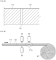
- FIGS. 2A to 2G are cross-sectional views and plan views for explaining the method for manufacturing a secondary battery according to an embodiment of the present invention.
- the method for manufacturing a secondary battery according to an embodiment of the present invention includes an active material layer forming step (S1), an active material layer removing step (S2) and a cutting step (S3).
- the method for manufacturing a secondary battery according to an embodiment of the present invention shown in FIG. 1 particularly relates to an electrode plate constituting the secondary battery.
- the electrode plate may be, for example, a positive electrode plate, but all features of the following description can also be applied to a negative electrode plate as well.
- an active material is coated on both surfaces of a current collector plate 111.
- the active material is coated on both surfaces of the current collector plate 111 unwound from an unwinding roller 10 to form an active material layer 112.
- the active material is discharged through a slot die 20 and is uniformly coated on both surfaces of the current collector plate 111.
- the current collector plate 111 may be formed of a metal foil made of aluminum or an aluminum alloy, or a mesh, and the active material may include a transition metal oxide.
- the active material layer 112 is continuously formed on the entire surface of the current collector plate 111.
- coating productivity can be improved and battery capacity can be increased, compared to a case where the active material layer 112 is intermittently formed on the current collector plate 111.
- the current collector plate 111 is cut as long as required to be used by a user, which will later be described in detail.
- a portion of the active material layer 112 is removed by irradiating a laser beam to the current collector plate 111.
- a first laser part 30 is positioned on top and bottom surfaces of the current collector plate 111.
- the first laser part 30 may be installed on the same line with the slot die 20 through which the active material is discharged or on a separate line, but the position of the first laser part 30 is not limited by the present invention.
- the first laser part 30 may include, for example, a laser oscillator for oscillating a laser beam, an expander for expanding the size of the laser beam, and a scanner focusing lens unit for scanning and focusing the laser beam on the current collector plate, but the construction of the first laser part 30 is not limited by the present invention.
- the laser beam may be based on pulsed waves.
- a general infrared (IR) laser oscillator of carbon dioxide, YAG, helium, neon, etc., may be used as the first laser part 30.
- the present invention does not limit the kind of a laser oscillator used to those listed herein.
- the laser beam generated from the first laser part 30 is irradiated to the current collector plate 111 having the active material layer 112 formed thereon to remove a portion of the active material layer 112. Accordingly, portions of the active material layer 112 formed on the top and bottom surfaces of the current collector plate 111 are removed.
- the active material layer removing step (S2) only the active material layer 112 formed on the top surface of the current collector plate 111 or only the active material layer 112 formed on the bottom surface of the current collector plate 111 may be removed.
- both of the active material layer 112 formed on the top surface and the active material layer 112 formed on the bottom surface of the current collector plate 111 are preferably removed.
- the active material layer removing step (S2) a portion of the active material layer 112 is removed in a direction perpendicular to a winding direction of the current collector plate 111.
- the laser beam may have a pulse width in the range from approximately 5 nsec to approximately 100 nsec, a peak power in the range from approximately 10 KW to approximately 50 KW, and an output capacity in the range from approximately 20 W to approximately 200 W.
- the active material layer 112 may not be perfectly removed. If the output capacity of the laser beam is greater than approximately 200 W, a portion of the current collector plate 111 as well as the active material layer 112 may be removed.
- the first laser part 30 may be an infrared pulse laser having a wavelength in the range from approximately 1030 nm to approximately 1080 nm. As described above, the current collector plate 111 from which the active material layer 112 has been removed may be transferred to a subsequent process by the winding roller 50.
- the current collector plate 111 is cut by irradiating a laser beam to the collector plate 111 from which the active material layer has been removed in the active material layer removing step (S2).
- a second laser part 40 is positioned on the current collector plate 111.
- the second laser part 40 may be based on continuous waves.
- a diode or semiconductor pump single mode continuous wave laser oscillator may be used.
- a general infrared (IR) laser oscillator of carbon dioxide, YAG, helium, neon, etc. may be used as the second laser part 40.
- the present invention does not limit the kind of a laser oscillator used to those listed herein.
- the second laser part 40 is positioned on the same line with the first laser part 30. Therefore, if the current collector plate 111 from which the active material layer has been removed by the first laser part 30 is transferred to a position of the second laser part 40 by the winding roller 50, as shown in FIGS. 2E and 2F , the second laser part 40 irradiates a laser beam to cut the current collector plate 111. Accordingly, the manufacture of the electrode plate 110 (positive electrode plate) is completed.
- an electrode plate is cut as long as required using a mold in a state in which an active material is coated on the electrode plate.
- the active material in a cutting region is scattered in forms of particles, a defect may be caused due to contamination.
- a burr may occur to the cut surface with the use of the mold, thereby resulting in an electrical short between electrode plates.
- the active material in the cutting region is first removed and the electrode plate is then cut using a laser beam, thereby preventing contamination due to the active material and an electrical short due to the burr, consequently improving the quality of the cut surface.
- the laser beam may have an output capacity of 300 W to 1 KW.
- the output capacity of the laser beam is smaller than 300 W, the current collector plate 111 may not be properly cut.
- the laser beam irradiated from the second laser part 40 may be an infrared pulse laser having a wavelength in the range from approximately 1030 nm to approximately 1080 nm.
- the cut surface 111a of the current collector plate 111 cut by a laser beam generated from the second laser part 40 is approximately 0.1 mm to approximately 3 mm from the active material layer 112. That is to say, the non-coating portion 114 from which the active material has been removed by the first laser part 30 is formed between the cut surface 111a and the active material layer 112 to have a width W1 in the range from approximately 0.1 mm to approximately 3 mm.
- the width W1 of the non-coating portion 114 is smaller than 0.1mm, a portion of the current collector plate 111 having the active material layer 112 formed thereon may be fused by the laser beam when the cut surface 111a is formed by cutting the current collector plate 111.
- the width W1 of the non-coating portion 114 is greater than 3 mm, suggesting that the active material has been excessively removed, the capacity of the secondary battery per unit area may become lowered.
- a bead part 113 is formed on the cut surface 111a.
- the bead part 113 may be a kind of dross formed due to the fusing of the current collector plate 111 when the current collector plate 111 is fused by the laser beam.
- the bead part 113 since the bead part 113 is formed from the current collector plate 111 fused by the laser beam and cooled, it may have a roughly circular cross-section due to surface tension. That is to say, the bead part 113 may have a roughly circular and/or oval cross-section perpendicular to a lengthwise direction of the current collector plate 111.
- the bead part 113 may be formed to have a width W2 in the range from approximately 1 ⁇ m to approximately 100 ⁇ m, preferably in the range from approximately 30 ⁇ m to approximately 40 ⁇ m.
- a width W2 in the range from approximately 1 ⁇ m to approximately 100 ⁇ m, preferably in the range from approximately 30 ⁇ m to approximately 40 ⁇ m.
- the width W2 of the bead part 113 can be controlled to be smaller than approximately 100 ⁇ m by adjusting the output capacity of the laser beam.
- the current collector plate 111 is cut after removing the active material from a portion to be cut using the laser beam, contamination due to the active material and electrical short due to burrs can be prevented, thereby increasing the quality of the cut surface 111a. Accordingly, the secondary battery according to the present invention can be improved.
- the bead part 113 similar to a circle, an ellipse or a welding bead having a uniform thickness and/or diameter is formed on the cut surface 111a, the bead part 113 can be prevented from penetrating into a separator for separating electrode plates from each other, thereby suppressing occurrence of electrical shorts.
- the bead part 113 is formed to have a substantially round surface, it is possible to prevent the separator from being torn or damaged by the bead part 113 even with a direct contact between the bead part 113 and the separator.
- the aforementioned electrode plate 110 will be defined as a first electrode plate (i.e., a positive electrode plate).
- a second electrode plate i.e., a negative electrode plate
- a description thereof will not be given.
- FIG. 3 is an exploded perspective view of a secondary battery according to an embodiment of the present invention.
- FIG. 4 is an exploded perspective view of an electrode assembly.
- the secondary 300 battery may include an electrode assembly 100 and a pouch 200.
- the electrode assembly 100 includes a first electrode plate 110, a second electrode plate 120 and a separator 130 interposed between the first electrode plate 110 and the second electrode plate 120.
- the electrode assembly 100 is configured such that a stacked structure of the first electrode plate 110, the second electrode plate 120 and the separator 130 is wound in a jelly-roll configuration.
- the first electrode plate 110 may function as a positive electrode
- the second electrode plate 120 may function as a negative electrode.
- the first electrode plate 110 includes a first current collector plate 111 formed of a metal foil or mesh made of, for example, aluminum or an aluminum alloy, a first active material layer 112 formed by coating a first active material, such as a transition metal oxide, on the first current collector plate 111, and a first non-coating portion 114 on which the first active material is not coated.
- the first electrode plate 110 includes a cut surface 111a formed at opposite ends in a lengthwise direction of the first current collector plate 111, and a bead part 113 formed on the cut surface 111a.
- the cut surface 111a is a surface cut by a laser beam to form the first electrode plate 110.
- a cross-sectional shape of the bead part 113 may be roughly circular due to surface tension. That is to say, the bead part 113 may have a roughly circular and/or oval cross-section perpendicular to the lengthwise direction of the first current collector plate 111.
- the bead part 113 may have a greater thickness than the first current collector plate 111.
- the bead part 113 may be formed to have a width W2 in the range from approximately 1 ⁇ m to approximately 100 ⁇ m, preferably in the range from approximately 30 ⁇ m to approximately 40 ⁇ m.
- the width W2 of the bead part 113 can be controlled to be smaller than approximately 100 ⁇ m by adjusting the output capacity of the laser beam.
- the first non-coating portion 114 is formed at opposite sides in the lengthwise direction of the first current collector plate 111. That is to say, the first non-coating portion 114 is positioned between the cut surface 111a and the first active material layer 112.
- the width W1 of the first non-coating portion 114 is in the range from approximately 0.1 mm to approximately 3 mm.
- the width W1 of the first non-coating portion 114 is smaller than 0.1mm, a portion of the first current collector plate 111 having the active material layer 112 formed thereon may be fused by the laser beam when the cut surface 111a is formed by cutting the first current collector plate 111.
- the width W1 of the first non-coating portion 114 is greater than 3 mm, suggesting that the active material has been excessively removed, the capacity of the secondary battery per unit area may become lowered.
- first non-coating portion 114 is further formed at one side perpendicular to the lengthwise direction of the first current collector plate 111, and a first electrode tab 115 is attached to the first non-coating portion 114.
- the first electrode tab 115 may be attached to the first non-coating portion 114 using an adhesive member 115a.
- the first non-coating portion 114 having the first electrode tab 115 attached thereto may be formed by removing a portion of the first active material layer 112 formed on the first current collector plate 111.
- the first non-coating portion 114 may also be formed by not coating the active material on the one side perpendicular to the lengthwise direction of the first current collector plate 111 when the first electrode plate 110 is formed. In this case, the first non-coating portion itself may serve as a first electrode tab.
- the second electrode plate 120 includes a second current collector plate 121 formed of a metal foil or mesh made of, for example, copper, a copper alloy, nickel or a nickel alloy, a second active material layer 122 formed by coating a second active material, such as graphite or carbon, on the second current collector plate 121, and a second non-coating portion 124 on which the second active material is not coated.
- the second electrode plate 120 includes a cut surface 121a formed at opposite ends in a lengthwise direction of the second current collector plate 121, and a bead part 123 formed on the cut surface 121a.
- the cut surface 121a is a surface cut by a laser beam to form the second electrode plate 120.
- a cross-sectional shape of the bead part 123 may be roughly circular due to surface tension. That is to say, the bead part 123 may have a roughly circular and/or oval cross-section perpendicular to the lengthwise direction of the second current collector plate 121.
- the bead part 123 may have a greater thickness than the second current collector plate 121.
- the bead part 123 may be formed to have a width W2 in the range from approximately 1 ⁇ m to approximately 100 ⁇ m, preferably in the range from approximately 30 ⁇ m to approximately 40 ⁇ m.
- the width W2 of the bead part 123 can be controlled to be smaller than approximately 100 ⁇ m by adjusting the output capacity of the laser beam.
- the second non-coating portion 124 is formed at opposite sides in the lengthwise direction of the second current collector plate 121. That is to say, the second non-coating portion 124 is positioned between the cut surface 121a and the second active material layer 122.
- the width W1 of the second non-coating portion 124 is in the range from approximately 0.1 mm to approximately 3 mm.
- the width W1 of the second non-coating portion 124 is smaller than 0.1mm, a portion of the second current collector plate 121 having the active material layer 122 formed thereon may be fused by the laser beam when the cut surface 121a is formed by cutting the second current collector plate 121.
- the width W1 of the second non-coating portion 124 is greater than 3 mm, suggesting that the active material has been excessively removed, the capacity of the secondary battery per unit area may become lowered.
- the second non-coating portion 124 is further formed at one side perpendicular to the lengthwise direction of the second current collector plate 121, and a second electrode tab 125 is attached to the second non-coating portion 124.
- the second electrode tab 125 may be attached to the second non-coating portion 124 using an adhesive member 125a.
- the second non-coating portion 124 having the second electrode tab 125 attached thereto may be formed by removing a portion of the second active material layer 122 formed on the second current collector plate 121.
- the second non-coating portion 124 may also be formed by not coating the active material on the one side perpendicular to the lengthwise direction of the second current collector plate 121 when the second electrode plate 120 is formed. In this case, the second non-coating portion itself may serve as a second electrode tab.
- the separator 130 positioned between the first electrode plate 110 and the second electrode plate 120 to prevent electrical shorts and to allow movement of lithium ions.
- the separator 130 may be made of polyethylene (PE), polypropylene (PP), or a copolymer of PE and PP.
- the electrode assembly 100 is accommodated in the case 200 along with an electrolyte.
- the electrolyte may include an organic solvent, such as EC (ethylene carbonate), PC (propylene carbonate), DEC (diethyl carbonate), EMC (ethyl methyl carbonate), or DMC (dimethyl carbonate), and a lithium salt, such as lithium hexafluorophosphate (LiPF 6 ) or lithium tetrafluoroborate (LiBF 4 ).
- the electrolyte may be in a liquid, solid, or gel phase.
- the case 200 is formed in a pouch type.
- the case 200 includes a first pouch 210 in which the electrode assembly 100 is received and a second pouch 220 combined with the first pouch 210.
- the case 200 is defined by the first pouch 210 and the second pouch 220 by bending a middle portion of an integrally formed hexahedral pouch film.
- the first pouch 210 includes a receiving groove 211, in which the electrode assembly 100 is to be received, formed therein by pressing, and a sealing part 212 for sealing the first pouch 210 with the second pouch 220.
- the sealing part 212 may be formed along one side, on which the first pouch 210 and the second pouch 220 are integrally brought into contact with each other, and the rest three sides.
- the case 200 includes two long sides on which the first pouch 210 and the second pouch 220 are brought into contact with each other, and two short sides perpendicular to the two long sides and facing each other.
- the first electrode tab 115 and the second electrode tab 125 of the electrode assembly 100 are drawn out through one of the two short sides, which faces the other short side connected to the first pouch 210 and the second pouch 220 (?).
- first and second insulation members 115b and 125b respectively formed in the first electrode tab 115 and the second electrode tab 125 are sealed to the sealing part 212.
- first and second insulation members 115b and 125b are formed at contact portions of the first and second electrode tabs 115 and 125 and the sealing part 212 to prevent the first and second electrode tabs 115 and 125 from being electrically shorted to the case 200.
- the electrode plates 110 and 120 formed by the aforementioned manufacturing method are applied to a pouch type secondary battery
- the electrode plates 110 and 120 may also be applied to a prismatic secondary battery, a cylindrical secondary battery and/or a medium-/large-sized secondary battery module having a plurality of prismatic secondary batteries connected to each other. That is to say, the electrode plates 110 and 120 may be applied to various types of secondary batteries, and the invention is not limited to the types of secondary batteries disclosed herein.
Landscapes
- Engineering & Computer Science (AREA)
- Chemical & Material Sciences (AREA)
- Chemical Kinetics & Catalysis (AREA)
- Electrochemistry (AREA)
- General Chemical & Material Sciences (AREA)
- Manufacturing & Machinery (AREA)
- Physics & Mathematics (AREA)
- Optics & Photonics (AREA)
- Plasma & Fusion (AREA)
- Mechanical Engineering (AREA)
- Materials Engineering (AREA)
- Battery Electrode And Active Subsutance (AREA)
Applications Claiming Priority (2)
| Application Number | Priority Date | Filing Date | Title |
|---|---|---|---|
| KR1020160080099A KR20180001229A (ko) | 2016-06-27 | 2016-06-27 | 이차 전지의 제조 방법 및 이를 이용한 이차 전지 |
| PCT/KR2017/006464 WO2018004177A1 (ko) | 2016-06-27 | 2017-06-20 | 이차 전지의 제조 방법 및 이를 이용한 이차 전지 |
Publications (2)
| Publication Number | Publication Date |
|---|---|
| EP3477754A1 true EP3477754A1 (de) | 2019-05-01 |
| EP3477754A4 EP3477754A4 (de) | 2020-01-22 |
Family
ID=60785149
Family Applications (1)
| Application Number | Title | Priority Date | Filing Date |
|---|---|---|---|
| EP17820454.1A Pending EP3477754A4 (de) | 2016-06-27 | 2017-06-20 | Verfahren zur herstellung einer sekundärbatterie und sekundärbatterie mit verwendung davon |
Country Status (5)
| Country | Link |
|---|---|
| US (1) | US11217780B2 (de) |
| EP (1) | EP3477754A4 (de) |
| KR (2) | KR20180001229A (de) |
| CN (1) | CN109328412A (de) |
| WO (1) | WO2018004177A1 (de) |
Cited By (5)
| Publication number | Priority date | Publication date | Assignee | Title |
|---|---|---|---|---|
| DE102019209183A1 (de) * | 2019-06-25 | 2020-12-31 | Volkswagen Aktiengesellschaft | Verfahren zur Herstellung von Batterieelektroden |
| US11515526B2 (en) | 2018-03-20 | 2022-11-29 | Lg Energy Solution, Ltd. | Method for manufacturing negative electrode and negative electrode obtained therefrom |
| EP4104965A1 (de) * | 2021-06-17 | 2022-12-21 | Shenzhen Geesun Intelligent Technology Co., Ltd. | Laserschneideverfahren |
| DE102021210784A1 (de) | 2021-09-28 | 2023-03-30 | Volkswagen Aktiengesellschaft | Verfahren zur Herstellung einer strukturierten Elektrodenlage für eine Lithium-Ionen-Batteriezelle |
| DE102024113651A1 (de) * | 2024-05-15 | 2025-11-20 | TRUMPF Laser- und Systemtechnik SE | Fertigungsverfahren und Fertigungsstrecke zum Herstellen von Elektroden |
Families Citing this family (22)
| Publication number | Priority date | Publication date | Assignee | Title |
|---|---|---|---|---|
| JP6885310B2 (ja) | 2017-11-28 | 2021-06-09 | トヨタ自動車株式会社 | 電極シート製造装置および蓄電装置の製造方法 |
| WO2019167559A1 (ja) * | 2018-02-28 | 2019-09-06 | パナソニック株式会社 | 二次電池用の電極、及び、これを用いた二次電池 |
| US20200266418A1 (en) * | 2018-03-23 | 2020-08-20 | EnPower, Inc. | Gap section multilayer electrode profile |
| JP7183707B2 (ja) * | 2018-08-10 | 2022-12-06 | 株式会社豊田自動織機 | 負極及び負極の製造方法並びに電極用結着剤 |
| EP3902030B1 (de) * | 2018-12-19 | 2025-09-03 | SANYO Electric Co., Ltd. | Sekundärbatterieelektrodenplatte und sekundärbatterie damit |
| CN113169428B (zh) | 2018-12-27 | 2023-03-28 | 三洋电机株式会社 | 二次电池 |
| JPWO2020137715A1 (ja) * | 2018-12-27 | 2021-11-11 | 三洋電機株式会社 | 電極板及びそれを用いた二次電池 |
| EP3930034A4 (de) * | 2019-02-20 | 2022-04-06 | SANYO Electric Co., Ltd. | Elektrodenplatte und verfahren zu ihrer herstellung sowie sekundärbatterie und verfahren zu ihrer herstellung |
| KR102803271B1 (ko) * | 2019-10-24 | 2025-05-07 | 주식회사 엘지에너지솔루션 | 레이저 식각을 이용한 전극 제조방법 및 이를 수행하는 전극 제조설비 |
| KR102926760B1 (ko) | 2020-02-07 | 2026-02-11 | 주식회사 엘지에너지솔루션 | 레이저를 이용한 클리닝 단계를 포함하는 전극 제조방법, 상기 방법으로 제조된 전극 및 이를 포함하는 이차전지 |
| US11688843B2 (en) * | 2020-08-31 | 2023-06-27 | GM Global Technology Operations LLC | Calendered electrode and method of making same |
| JP7168622B2 (ja) * | 2020-09-08 | 2022-11-09 | プライムプラネットエナジー&ソリューションズ株式会社 | 電池およびその製造方法 |
| WO2022140123A1 (en) * | 2020-12-22 | 2022-06-30 | Sion Power Corporation | Laser cutting of components for electrochemical cells |
| DE202021004550U1 (de) | 2021-01-08 | 2025-11-10 | Sk On Co., Ltd. | Elektrode und Sekundärbatterie mit derselben |
| WO2022209161A1 (ja) * | 2021-03-29 | 2022-10-06 | パナソニックIpマネジメント株式会社 | 切断装置および切断方法 |
| KR102904350B1 (ko) * | 2021-04-22 | 2025-12-26 | 주식회사 엘지화학 | 전극 조립체 제조 방법 및 전극 조립체 제조 시스템 |
| DE102021205500A1 (de) * | 2021-05-31 | 2022-12-01 | Volkswagen Aktiengesellschaft | Verfahren zur Herstellung einer Batterieelektrode |
| DE212022000208U1 (de) * | 2021-07-19 | 2024-02-20 | Lg Energy Solution, Ltd. | Verarbeitetes Elektrodenblatt und Vorrichtung zur Verarbeitung eines Elektrodenblatts |
| JP7798578B2 (ja) * | 2022-01-11 | 2026-01-14 | トヨタ自動車株式会社 | 電極の製造方法 |
| EP4325592A4 (de) * | 2022-04-07 | 2025-08-06 | Lg Energy Solution Ltd | Elektrodenformsteuerungsverfahren und elektrodenherstellungsverfahren |
| KR102649478B1 (ko) * | 2022-08-29 | 2024-03-20 | 주식회사 필에너지 | 2차전지 전극판의 디버링 장치 및 그 방법 |
| KR20240102909A (ko) * | 2022-12-26 | 2024-07-03 | 주식회사 엘지에너지솔루션 | 건식 전극 제조 방법 및 건식 전극 제조 시스템 |
Family Cites Families (14)
| Publication number | Priority date | Publication date | Assignee | Title |
|---|---|---|---|---|
| KR100477725B1 (ko) | 1997-08-28 | 2005-05-16 | 삼성에스디아이 주식회사 | 전지의극판절단장치 |
| JP4023990B2 (ja) | 2000-08-30 | 2007-12-19 | 松下電器産業株式会社 | 電池用電極板の製造方法および製造装置 |
| KR100391931B1 (ko) * | 2000-10-16 | 2003-07-22 | 박사인 | 리튬 이차전지용 전극 제조방법 |
| US20030215700A1 (en) * | 2002-04-04 | 2003-11-20 | Kenichiro Hosoda | Nonaqueous electrolyte secondary battery |
| KR101093306B1 (ko) * | 2007-05-18 | 2011-12-14 | 주식회사 엘지화학 | 파이버 펄스형 레이저를 이용한 리튬 이차전지 전극의제조방법 |
| JP5354646B2 (ja) * | 2008-07-31 | 2013-11-27 | Necエナジーデバイス株式会社 | 積層型二次電池およびその製造方法 |
| DE102010062140B4 (de) * | 2010-11-29 | 2014-04-03 | Zentrum für Sonnenenergie- und Wasserstoff-Forschung Baden-Württemberg Gemeinnützige Stiftung | Batterieelektrode und Verfahren zum Herstellen derselben, sowie Batterie |
| JP2012221913A (ja) * | 2011-04-14 | 2012-11-12 | Nissan Motor Co Ltd | 電極製造方法及びレーザーカット装置 |
| KR101278044B1 (ko) | 2011-08-08 | 2013-06-24 | 주식회사 엘티에스 | 레이저를 이용한 이차전지용 전극 절단방법 |
| KR102009932B1 (ko) | 2011-11-15 | 2019-08-12 | 퀸시 바이오사이언스 엘엘씨 | 허혈로 인한 뉴런 손상을 감소시키기 위한 아포에쿼린 |
| KR101719031B1 (ko) * | 2014-04-24 | 2017-03-22 | 주식회사 엘지화학 | 폴리머 전지 전극 제조 방법 및 폴리머 전지 전극 제조 장치 |
| KR101804614B1 (ko) | 2014-06-13 | 2017-12-06 | 주식회사 엘지화학 | 음극에 리드를 용접하는 방법, 이에 의해 제조된 배터리용 음극 및 이를 포함하는 이차전지 |
| US10122010B2 (en) * | 2014-07-11 | 2018-11-06 | Semiconductor Energy Laboratory Co., Ltd. | Secondary battery and electronic device including the same |
| KR102177506B1 (ko) * | 2014-07-30 | 2020-11-11 | 삼성에스디아이 주식회사 | 이차 전지 및 그 제조 방법 |
-
2016
- 2016-06-27 KR KR1020160080099A patent/KR20180001229A/ko not_active Ceased
-
2017
- 2017-06-20 EP EP17820454.1A patent/EP3477754A4/de active Pending
- 2017-06-20 CN CN201780040039.8A patent/CN109328412A/zh active Pending
- 2017-06-20 US US16/312,913 patent/US11217780B2/en active Active
- 2017-06-20 WO PCT/KR2017/006464 patent/WO2018004177A1/ko not_active Ceased
-
2024
- 2024-05-28 KR KR1020240069194A patent/KR102894754B1/ko active Active
Cited By (5)
| Publication number | Priority date | Publication date | Assignee | Title |
|---|---|---|---|---|
| US11515526B2 (en) | 2018-03-20 | 2022-11-29 | Lg Energy Solution, Ltd. | Method for manufacturing negative electrode and negative electrode obtained therefrom |
| DE102019209183A1 (de) * | 2019-06-25 | 2020-12-31 | Volkswagen Aktiengesellschaft | Verfahren zur Herstellung von Batterieelektroden |
| EP4104965A1 (de) * | 2021-06-17 | 2022-12-21 | Shenzhen Geesun Intelligent Technology Co., Ltd. | Laserschneideverfahren |
| DE102021210784A1 (de) | 2021-09-28 | 2023-03-30 | Volkswagen Aktiengesellschaft | Verfahren zur Herstellung einer strukturierten Elektrodenlage für eine Lithium-Ionen-Batteriezelle |
| DE102024113651A1 (de) * | 2024-05-15 | 2025-11-20 | TRUMPF Laser- und Systemtechnik SE | Fertigungsverfahren und Fertigungsstrecke zum Herstellen von Elektroden |
Also Published As
| Publication number | Publication date |
|---|---|
| CN109328412A (zh) | 2019-02-12 |
| WO2018004177A1 (ko) | 2018-01-04 |
| KR20240084522A (ko) | 2024-06-13 |
| KR102894754B1 (ko) | 2025-12-03 |
| EP3477754A4 (de) | 2020-01-22 |
| KR20180001229A (ko) | 2018-01-04 |
| US11217780B2 (en) | 2022-01-04 |
| US20190267608A1 (en) | 2019-08-29 |
Similar Documents
| Publication | Publication Date | Title |
|---|---|---|
| US11217780B2 (en) | Method for manufacturing secondary battery and secondary battery using same | |
| CN105322213B (zh) | 可再充电电池及其制造方法 | |
| KR102751962B1 (ko) | 전극 탭 절곡 장치 및 방법 | |
| KR101224275B1 (ko) | 적층형 이차 전지 및 그 제조 방법 | |
| CN110326130B (zh) | 具有改善的电极接片焊接特性的电极及包括该电极的二次电池 | |
| US8025202B2 (en) | Method for manufacturing sealed battery | |
| US20110195288A1 (en) | Sealed battery and method for fabricating the same | |
| KR101675623B1 (ko) | 이차 전지 및 그 제조 방법 | |
| KR102564562B1 (ko) | 전극 조립체, 이차 전지 및 보호 테이프 부착 장치 | |
| US10749204B2 (en) | Electric power storage device and method of manufacturing the same | |
| KR20210138400A (ko) | 전극 탭 용접 장치 및 방법 | |
| JP4961673B2 (ja) | 非水電解質電池用タブリードの製造方法 | |
| JP2014504429A (ja) | シート状あるいはプレート状のオブジェクトを切断する方法およびシステム | |
| KR101116533B1 (ko) | 이차 전지 및 그 제조 방법 | |
| KR20220140417A (ko) | 전극 조립체, 배터리 셀, 배터리 셀 가공장치, 이를 포함하는 배터리 팩 및 차량 | |
| CN101262047B (zh) | 充电电池盒及其制造方法 | |
| KR102404455B1 (ko) | 배터리 셀용 필름 스택의 제조 방법 | |
| JP4603857B2 (ja) | リチウムイオン二次電池およびその製造方法 | |
| KR102504792B1 (ko) | 이차 전지 | |
| EP4123792A1 (de) | Beutelartige sekundärbatterie und verfahren zur herstellung davon | |
| KR102052589B1 (ko) | 이차 전지용 전극, 이를 포함하는 이차 전지, 및 이차 전지용 전극의 제조 방법 | |
| KR20230013599A (ko) | 파우치형 이차전지 및 이의 제조방법 | |
| CN218333917U (zh) | 剪裁装置、电极组件、电池单元、其加工装置、含其的电池组及车辆 | |
| KR20170114404A (ko) | 이차 전지 | |
| KR101867650B1 (ko) | 만입형 단차가 형성되어 있는 전지케이스를 포함하는 전지셀 |
Legal Events
| Date | Code | Title | Description |
|---|---|---|---|
| STAA | Information on the status of an ep patent application or granted ep patent |
Free format text: STATUS: THE INTERNATIONAL PUBLICATION HAS BEEN MADE |
|
| PUAI | Public reference made under article 153(3) epc to a published international application that has entered the european phase |
Free format text: ORIGINAL CODE: 0009012 |
|
| STAA | Information on the status of an ep patent application or granted ep patent |
Free format text: STATUS: REQUEST FOR EXAMINATION WAS MADE |
|
| 17P | Request for examination filed |
Effective date: 20181218 |
|
| AK | Designated contracting states |
Kind code of ref document: A1 Designated state(s): AL AT BE BG CH CY CZ DE DK EE ES FI FR GB GR HR HU IE IS IT LI LT LU LV MC MK MT NL NO PL PT RO RS SE SI SK SM TR |
|
| AX | Request for extension of the european patent |
Extension state: BA ME |
|
| DAV | Request for validation of the european patent (deleted) | ||
| DAX | Request for extension of the european patent (deleted) | ||
| A4 | Supplementary search report drawn up and despatched |
Effective date: 20191220 |
|
| RIC1 | Information provided on ipc code assigned before grant |
Ipc: H01M 4/64 20060101ALI20191216BHEP Ipc: H01M 4/04 20060101ALI20191216BHEP Ipc: H01M 10/0587 20100101ALI20191216BHEP Ipc: H01M 10/04 20060101AFI20191216BHEP Ipc: H01M 4/139 20100101ALI20191216BHEP Ipc: H01M 10/058 20100101ALI20191216BHEP |
|
| STAA | Information on the status of an ep patent application or granted ep patent |
Free format text: STATUS: EXAMINATION IS IN PROGRESS |
|
| 17Q | First examination report despatched |
Effective date: 20211102 |