EP3477778A1 - Unité de raccordement et d'étanchéité pour une conduite électrique isolé et son procédé de fabrication - Google Patents
Unité de raccordement et d'étanchéité pour une conduite électrique isolé et son procédé de fabrication Download PDFInfo
- Publication number
- EP3477778A1 EP3477778A1 EP17306460.1A EP17306460A EP3477778A1 EP 3477778 A1 EP3477778 A1 EP 3477778A1 EP 17306460 A EP17306460 A EP 17306460A EP 3477778 A1 EP3477778 A1 EP 3477778A1
- Authority
- EP
- European Patent Office
- Prior art keywords
- connection
- sleeve
- sealing unit
- sealing
- insulation
- Prior art date
- Legal status (The legal status is an assumption and is not a legal conclusion. Google has not performed a legal analysis and makes no representation as to the accuracy of the status listed.)
- Granted
Links
Images

Classifications
-
- H—ELECTRICITY
- H01—ELECTRIC ELEMENTS
- H01R—ELECTRICALLY-CONDUCTIVE CONNECTIONS; STRUCTURAL ASSOCIATIONS OF A PLURALITY OF MUTUALLY-INSULATED ELECTRICAL CONNECTING ELEMENTS; COUPLING DEVICES; CURRENT COLLECTORS
- H01R4/00—Electrically-conductive connections between two or more conductive members in direct contact, i.e. touching one another; Means for effecting or maintaining such contact; Electrically-conductive connections having two or more spaced connecting locations for conductors and using contact members penetrating insulation
- H01R4/10—Electrically-conductive connections between two or more conductive members in direct contact, i.e. touching one another; Means for effecting or maintaining such contact; Electrically-conductive connections having two or more spaced connecting locations for conductors and using contact members penetrating insulation effected solely by twisting, wrapping, bending, crimping, or other permanent deformation
- H01R4/18—Electrically-conductive connections between two or more conductive members in direct contact, i.e. touching one another; Means for effecting or maintaining such contact; Electrically-conductive connections having two or more spaced connecting locations for conductors and using contact members penetrating insulation effected solely by twisting, wrapping, bending, crimping, or other permanent deformation by crimping
- H01R4/20—Electrically-conductive connections between two or more conductive members in direct contact, i.e. touching one another; Means for effecting or maintaining such contact; Electrically-conductive connections having two or more spaced connecting locations for conductors and using contact members penetrating insulation effected solely by twisting, wrapping, bending, crimping, or other permanent deformation by crimping using a crimping sleeve
-
- H—ELECTRICITY
- H01—ELECTRIC ELEMENTS
- H01R—ELECTRICALLY-CONDUCTIVE CONNECTIONS; STRUCTURAL ASSOCIATIONS OF A PLURALITY OF MUTUALLY-INSULATED ELECTRICAL CONNECTING ELEMENTS; COUPLING DEVICES; CURRENT COLLECTORS
- H01R43/00—Apparatus or processes specially adapted for manufacturing, assembling, maintaining, or repairing of line connectors or current collectors or for joining electric conductors
- H01R43/005—Apparatus or processes specially adapted for manufacturing, assembling, maintaining, or repairing of line connectors or current collectors or for joining electric conductors for making dustproof, splashproof, drip-proof, waterproof, or flameproof connection, coupling, or casing
-
- H—ELECTRICITY
- H01—ELECTRIC ELEMENTS
- H01R—ELECTRICALLY-CONDUCTIVE CONNECTIONS; STRUCTURAL ASSOCIATIONS OF A PLURALITY OF MUTUALLY-INSULATED ELECTRICAL CONNECTING ELEMENTS; COUPLING DEVICES; CURRENT COLLECTORS
- H01R13/00—Details of coupling devices of the kinds covered by groups H01R12/70 or H01R24/00 - H01R33/00
- H01R13/46—Bases; Cases
- H01R13/52—Dustproof, splashproof, drip-proof, waterproof, or flameproof cases
- H01R13/5205—Sealing means between cable and housing, e.g. grommet
-
- H—ELECTRICITY
- H01—ELECTRIC ELEMENTS
- H01R—ELECTRICALLY-CONDUCTIVE CONNECTIONS; STRUCTURAL ASSOCIATIONS OF A PLURALITY OF MUTUALLY-INSULATED ELECTRICAL CONNECTING ELEMENTS; COUPLING DEVICES; CURRENT COLLECTORS
- H01R4/00—Electrically-conductive connections between two or more conductive members in direct contact, i.e. touching one another; Means for effecting or maintaining such contact; Electrically-conductive connections having two or more spaced connecting locations for conductors and using contact members penetrating insulation
- H01R4/10—Electrically-conductive connections between two or more conductive members in direct contact, i.e. touching one another; Means for effecting or maintaining such contact; Electrically-conductive connections having two or more spaced connecting locations for conductors and using contact members penetrating insulation effected solely by twisting, wrapping, bending, crimping, or other permanent deformation
- H01R4/18—Electrically-conductive connections between two or more conductive members in direct contact, i.e. touching one another; Means for effecting or maintaining such contact; Electrically-conductive connections having two or more spaced connecting locations for conductors and using contact members penetrating insulation effected solely by twisting, wrapping, bending, crimping, or other permanent deformation by crimping
- H01R4/183—Electrically-conductive connections between two or more conductive members in direct contact, i.e. touching one another; Means for effecting or maintaining such contact; Electrically-conductive connections having two or more spaced connecting locations for conductors and using contact members penetrating insulation effected solely by twisting, wrapping, bending, crimping, or other permanent deformation by crimping for cylindrical elongated bodies, e.g. cables having circular cross-section
- H01R4/184—Electrically-conductive connections between two or more conductive members in direct contact, i.e. touching one another; Means for effecting or maintaining such contact; Electrically-conductive connections having two or more spaced connecting locations for conductors and using contact members penetrating insulation effected solely by twisting, wrapping, bending, crimping, or other permanent deformation by crimping for cylindrical elongated bodies, e.g. cables having circular cross-section comprising a U-shaped wire-receiving portion
- H01R4/185—Electrically-conductive connections between two or more conductive members in direct contact, i.e. touching one another; Means for effecting or maintaining such contact; Electrically-conductive connections having two or more spaced connecting locations for conductors and using contact members penetrating insulation effected solely by twisting, wrapping, bending, crimping, or other permanent deformation by crimping for cylindrical elongated bodies, e.g. cables having circular cross-section comprising a U-shaped wire-receiving portion combined with a U-shaped insulation-receiving portion
Definitions
- the invention relates to a connection and sealing unit for an insulated electrical line and to a method for producing a fluid-tight electrical connection using the connection and sealing unit.
- stop members which are non-detachably connected to the electrical lead, e.g. by means of a clamping or crimp connection.
- the stop member is then electrically connected to a corresponding receptacle of the electrical unit, for example by a self-locking connector or a screw connection.
- the electrical wiring and equipment may be exposed to harsh operating and environmental conditions, including mechanical shock, dirt, and moisture. Ingress of moisture between a conductor and insulation of an electrical line can cause corrosion or failure of the insulation so that the electrical connection is no longer safe. In order to reliably ensure a long service life of the electrical connection, it is necessary to prevent the ingress of dirt or moisture between the conductor and insulation of an electrical line. In particular, the sealing of insulated wires with stranded conductors, ie a bundle of individual wires, is complex and requires a variety of manual work steps.
- a conductive, plastically deformable sleeve is crimped over the stripped strands, so that a fluid-tight connection between the sleeve and strands is formed, and the transition region between the Sleeve and the insulation is sealed by means of the transition region cross-shrink tube against external environmental influences.
- a sealing compound for example an adhesive, can be provided on the inner side of the heat-shrinkable tube in order to increase the sealing effect.
- fluid-tight is used to denote the ingress of liquids and / or gases.
- Crimping is understood as meaning a joining process in which two components are joined together by plastic deformation, for example by crimping, crimping, crimping or folding.
- a crimp connection is only partially solvable and can be renewed for repairs only with suitable tools.
- the wires of a cable with a connecting element e.g. a plug or a wire end ferrule, non-positively and / or positively connected.
- a connecting element e.g. a plug or a wire end ferrule
- the force for plastic deformation of the conductor or connecting element usually acts via a knee lever, because the manual force is too weak for a permanent deformation process.
- a frictional connection occurs when two parts are connected by means of a normal force acting substantially perpendicular to the interconnected surfaces.
- a substantially radial force acts between the connecting element and the core bundle.
- a positive connection is created when two connected parts engage in such a way that their position relative to one another is unchangeable, at least in one direction.
- Known interlocking connections are, for example, the so-called dovetail connection, in which a connecting part, which widens toward one end in at least one dimension, engages in a correspondingly shaped receptacle.
- deformation of the connecting element and the wire bundle may occur come, for example, by partial displacement of material to the sides of a crimped ring, so that at least in one direction, a movement of the connected parts to each other is impossible.
- strain relief comes to lie on the insulation of the cable, and is not squeezed to the same extent as the wire crimping of the wire bundle.
- the strain relief must be strong enough so that the insulation does not slip through 45 ° under the insulation crimp by repeated bending. However, it must not be so strong that it breaks through the insulation, or even hurt individual strands.
- the present invention has the object to provide an improved connection and sealing unit, which makes it possible to produce a fluid-tight electrical connection between a stop member and an insulated electrical line with a few manual operations or completely automated.
- the invention proposes according to a first aspect, a connection and sealing unit for an insulated electrical line with a plastically deformable, electrically conductive sleeve and an at least in the radial direction elastically deformable sealing member.
- the sealing member abuts in a first region on the sleeve under mechanical tension and surrounds the sleeve coaxially completely.
- the mechanical stress acts on the sleeve due to the elastic deformability of the sealing part in the radial direction.
- the diameter of an opening in the sealing part, in which the sleeve is inserted in the assembled state be smaller than the diameter of the sleeve.
- the sealing member is in a second region over the circumference of an insulation of the electrical line with the insulation circumferentially fitting force, material and / or positive and fluid-tight connectable.
- the sleeve is connected in a third region, which is not enclosed by the sealing part, over the circumference of a conductor of the electrical line with this electrically conductive, non-positively and / or positively and fluid-tight manner.
- a radially deformable sealing part also comprises sealing parts that are stiffer in the axial direction than in the radial direction, which can be achieved, for example, by correspondingly inserted structures.
- the fluid-tight connections of conductor and sleeve, sleeve and sealing part as well as seal part and insulation prevent the penetration of fluids between the conductor and insulation.
- the fluid-tight connections can be created by plastic deformation of sleeve and / or conductors or sealing element and / or insulation. The plastic deformation involves a flow of material during deformation. When correctly mounted, the sleeve or the sealing element over the entire circumference of the conductor or the insulation is applied.
- the sealing member is a rotationally symmetrical hollow body with two open ends, for example.
- the openings of the hollow cylinder may have different diameters to compensate for differences between the outer diameters of the sleeve and the insulation of the electrical line and yet to ensure easy mounting.
- the transition between the open ends may be stepped, at least within the sealing part.
- the rotationally symmetrical hollow body externally retains a cylindrical shape, while the interior has a stepped course of the diameter.
- the stepped course of the inner diameter can form a stop for the isolation of the electrical line, whereby a simple positioning of the connection and sealing unit is made possible during assembly. But it can also remain a cavity between the step and the insulation, for example. To allow a bending movement of the electrical line. However, the cavity can also be reduced or eliminated by an additional crimp connection.
- an inner surface of the sealing unit bearing against the sleeve and / or insulation is provided with grooves or elevations encircling the circumference, so that a plurality of partial surfaces following one another in the axial direction abut circumferentially on the sleeve and / or the insulation.
- the sealing member between the second and the third region with the sleeve circumferentially fitting force and / or positive and fluid-tight connectable can be done, for example, by crimping.
- the end of the sealing part located above the insulation has an outwardly raised edge. This Edge can serve, for example, during assembly as a defined stop for a slid onto the connection and sealing unit stop member and thus facilitate processing.
- the terminal and sealing unit When mounting a stop member, the terminal and sealing unit is first pushed over a stripped end of the insulated wire so that the sleeve is over the wire, and a portion of the gasket over the insulation.
- the sleeve may be closed at the end facing away from the sealing part. If the connection and sealing unit is in two parts, first the sleeve is pushed over the stripped conductor, and then the sealing part over the sleeve and the insulation. In a next step, the stopper is pushed over the connection and sealing unit.
- the stop member has a first electrical contact surface and a first and a second plastically deformable structure.
- At least the first plastically deformable structure is electrically conductive and surrounds the connection and sealing unit in the mounted state in the third region, in which the sleeve is not enclosed by the sealing part.
- the second plastically deformable structure surrounds the connection and sealing unit in the assembled state in the second area, in which the sealing part is located above the insulation.
- the stop member has a third plastically deformable structure located between the first and second plastically deformable structures.
- the third plastically deformable structure surrounds the sealing part of the connection and sealing unit in the area lying above the sleeve.
- the stop member with the sleeve and the sealing member of the connection and sealing unit After pre-assembly, the stop member with the sleeve and the sealing member of the connection and sealing unit, the sleeve with the electrical conductor and the sealing member with the insulation non-positively and / or positively connected.
- the non-positive and / or positive connection can by deformation of the plastically deformable structures of the abutment part to a respective Connection area done, for example by crimping. In these areas, the plastically deformed areas of the abutment part exert a force acting radially on the sleeve or the sealing unit.
- the plastically deformable structures are designed so that they retain their shape after deformation.
- the plastically deformable structures can be slotted longitudinally or obliquely to an axial direction, wherein the slot after the deformation become narrower or can be eliminated by overlapping the opposite in the undeformed state parts of the plastically deformable structure.
- the ends of the parts of the plastically deformable structure that are opposite in the undeformed state can also come into contact with each other during the deformation and be bent inwardly in the radial direction.
- the optional cohesive connection of the sealing part with the insulation of the electrical line can be done, for example, by gluing or vulcanization.
- FIG. 1 shows a schematic exploded view of an exemplary connection and sealing unit with electrical line 1 and stop member 20. From left to right are shown in the figure, the stop member 20 with a first electrical contact surface 22, a first deformable structure 12, a third deformable structure 16 and a second deformable structure 14.
- the deformable structures may be an integral part of an integrally formed stop member 20 or, in the case of a multi-part stop member 20, be connected to the other parts of the stop member 20 inextricably.
- the deformable structures 12, 14, 16 of the exemplary connection and sealing unit are annular, so that they enclose an electrical conductor 8 or an insulation 6 of the electrical line 1 and / or a sleeve 2 of the connection and sealing unit over the entire circumference ,
- the annular deformable structures 12, 14, 16 are slotted obliquely to a coaxial direction, wherein the edges of the slots can slide over each other in the deformed state or can be bent in the radial direction.
- the slots may also run parallel to a coaxial direction (not shown in the figure).
- a sleeve 2 and a sealing part 3 of the connection and sealing unit are shown.
- a part of the sleeve 2 is inserted into the sealing unit 3.
- connection and sealing unit To the right of the components of the connection and sealing unit, an electrical line 1 with a stripped region 26 and an insulation 6 is shown.
- FIG. 2 shows an exemplary side and top view of an assembled with the connection and sealing unit and a stop member line.
- the deformable structures 12, 14, 16, the sleeve and the sealing part of the connection and sealing unit at different Surround bodies and connect to the electrical conductor or the insulation of the electrical line 1.
- the edge 10 of the sealing unit during assembly serves as a stop for the second deformable structure 14 when pushing the stop member 20, whereby the assembly of electrical lines is facilitated in consistently consistent quality of execution.
- matched combinations of stopper and connection and sealing unit can be kept, which can ensure that the deformable structures are always in the correct areas of the electrical line before deformation.
- FIG. 3 shows in the right part of the figure, the concentric arrangement of the annular deformable structures 12, 14, 16 of the stop member 20 can be seen, whereby the sliding of the stop member 20 on the Connection and sealing unit is facilitated after it has been pushed onto the electrical line 1.
- FIG. 3 is clearly visible as the first deformable structure 12 of the stop member 20 surrounds the sleeve 2 of the connection and sealing unit and connects to the electrical conductor 8 of the electrical line 1.
- the first plastically deformable structure 12 surrounds the connection and sealing unit in the mounted state in a third region 7, in which the sleeve 2 is not enclosed by the sealing part 3.
- the second deformable structure 14 encloses the sealing part 3 of the connection and sealing unit and presses it onto the insulation 6 of the electrical line 1.
- the third deformable structure 16 of the abutment part 20 surrounds the sealing part 3 of the connection and sealing unit in a region in which it the sleeve 2 engages, and presses this on the sleeve 2. This additional contact force, the sealing effect between the seal member 3 and sleeve 2 in addition to a mechanical bias, which exerts the seal member 3 on the sleeve 2, reinforce.
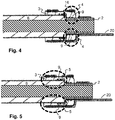
- FIG. 4 shows a detail of the sectional view FIG. 3
- the webs adjacent to the grooves can be pressed firmly against the surface of the sleeve 2 by the mechanical stress generated by the sealing part 3 or even be deformed by the mechanical stress.
- a stress generated by the deformation of the plastically deformable structure 16 of the stopper member 20 in the radial direction can act on the seal member 3 and the grooves.
- the grooves can serve as an alternative space for displaced by the deformation material and thus cause a uniform over the entire circumference of the sleeve 2 pressing force and tightness.
- FIG. 5 shows the same detail of the sectional view as FIG. 4 , however, are in FIG. 5
- Surfaces 9 shown with grooves in a second region 5.
- the function and effect is the same as with reference to FIG. 4 described function and effect of the surfaces with grooves.
Landscapes
- Engineering & Computer Science (AREA)
- Manufacturing & Machinery (AREA)
- Connector Housings Or Holding Contact Members (AREA)
Priority Applications (1)
| Application Number | Priority Date | Filing Date | Title |
|---|---|---|---|
| EP17306460.1A EP3477778B1 (fr) | 2017-10-24 | 2017-10-24 | Unité de raccordement et d'étanchéité pour une conduite électrique isolé et son procédé de fabrication |
Applications Claiming Priority (1)
| Application Number | Priority Date | Filing Date | Title |
|---|---|---|---|
| EP17306460.1A EP3477778B1 (fr) | 2017-10-24 | 2017-10-24 | Unité de raccordement et d'étanchéité pour une conduite électrique isolé et son procédé de fabrication |
Publications (2)
| Publication Number | Publication Date |
|---|---|
| EP3477778A1 true EP3477778A1 (fr) | 2019-05-01 |
| EP3477778B1 EP3477778B1 (fr) | 2020-12-09 |
Family
ID=60191310
Family Applications (1)
| Application Number | Title | Priority Date | Filing Date |
|---|---|---|---|
| EP17306460.1A Active EP3477778B1 (fr) | 2017-10-24 | 2017-10-24 | Unité de raccordement et d'étanchéité pour une conduite électrique isolé et son procédé de fabrication |
Country Status (1)
| Country | Link |
|---|---|
| EP (1) | EP3477778B1 (fr) |
Citations (7)
| Publication number | Priority date | Publication date | Assignee | Title |
|---|---|---|---|---|
| FR2543369A2 (fr) * | 1983-03-24 | 1984-09-28 | Francelco Sa | Dispositif d'etancheite pour connecteur electrique |
| JPH0355663U (fr) * | 1989-10-05 | 1991-05-29 | ||
| JP3259812B2 (ja) * | 1995-09-19 | 2002-02-25 | 矢崎総業株式会社 | 防水コネクタ用端子金具 |
| EP1981123A2 (fr) * | 2007-04-13 | 2008-10-15 | Sumitomo Wiring Systems, Ltd. | Pose de terminal et son procédé de gaufrage |
| DE102010009284A1 (de) * | 2010-02-25 | 2011-08-25 | Thomas Dr. 72525 Flottmann | Leitungseinheit mit Dichtfunktion |
| WO2011115005A1 (fr) * | 2010-03-16 | 2011-09-22 | 株式会社オートネットワーク技術研究所 | Câble comportant une fixation terminale et procédé de fabrication |
| US20120244759A1 (en) * | 2011-03-24 | 2012-09-27 | Sumitomo Wiring Systems, Ltd. | Terminal fitting |
-
2017
- 2017-10-24 EP EP17306460.1A patent/EP3477778B1/fr active Active
Patent Citations (7)
| Publication number | Priority date | Publication date | Assignee | Title |
|---|---|---|---|---|
| FR2543369A2 (fr) * | 1983-03-24 | 1984-09-28 | Francelco Sa | Dispositif d'etancheite pour connecteur electrique |
| JPH0355663U (fr) * | 1989-10-05 | 1991-05-29 | ||
| JP3259812B2 (ja) * | 1995-09-19 | 2002-02-25 | 矢崎総業株式会社 | 防水コネクタ用端子金具 |
| EP1981123A2 (fr) * | 2007-04-13 | 2008-10-15 | Sumitomo Wiring Systems, Ltd. | Pose de terminal et son procédé de gaufrage |
| DE102010009284A1 (de) * | 2010-02-25 | 2011-08-25 | Thomas Dr. 72525 Flottmann | Leitungseinheit mit Dichtfunktion |
| WO2011115005A1 (fr) * | 2010-03-16 | 2011-09-22 | 株式会社オートネットワーク技術研究所 | Câble comportant une fixation terminale et procédé de fabrication |
| US20120244759A1 (en) * | 2011-03-24 | 2012-09-27 | Sumitomo Wiring Systems, Ltd. | Terminal fitting |
Also Published As
| Publication number | Publication date |
|---|---|
| EP3477778B1 (fr) | 2020-12-09 |
Similar Documents
| Publication | Publication Date | Title |
|---|---|---|
| DE102010064071B3 (de) | Klemmring, Kabelverschraubung und Verfahren zum Montieren einer Kabelverschraubung | |
| DE102017131352B4 (de) | Leitungsverbinder sowie Herstellverfahren für eine elektrische Verbindung | |
| CH698708B1 (de) | Verbinder zum Verbinden eines Endes eines Koaxialkabels und Verfahren zum Anbringen des Verbinders. | |
| DE102016109882A1 (de) | Schnell trennbare elektrische Steckverbindung sowie Verfahren zur Kontaktierung eines elektrischen Kontaktelements mit einem elektrischen Leiter | |
| BE1025310B1 (de) | Steckverbinderteil mit verstemmten Kontaktelementen | |
| EP3329500B1 (fr) | Dispositif antidéflagrant pour traversée de boulon et son procédé de fabrication | |
| EP2245705B1 (fr) | Élément connecteur à fiche, à effet d'étanchéité dans la région de raccordement du câble | |
| DE3604093A1 (de) | Elektrischer steckverbinder fuer koaxialkabel und verfahren zu seiner herstellung | |
| DE202011002287U1 (de) | Kabelverschraubung für abgeschirmte Leitungen | |
| EP1837955A1 (fr) | Douille à maintien sécurisée pour un connecteur | |
| EP3477778B1 (fr) | Unité de raccordement et d'étanchéité pour une conduite électrique isolé et son procédé de fabrication | |
| DE102022202685A1 (de) | Steckverbinder und Verfahren zum Herstellen eines Steckverbinders | |
| DE102006028880A1 (de) | Kabelverbindung | |
| DE102015220685B4 (de) | Zugentlastungselement für eine Leitung, Aufnahmeeinrichtung, Zugentlastungsvorrichtung und Gehäuse | |
| DE102018124089A1 (de) | Kontakteinrichtung und Anordnung mit solch einer Kontakteinrichtung | |
| DE102008031686A1 (de) | Verbesserte Halteschutzbuchse eines Steckverbinders | |
| EP4066328B1 (fr) | Ensemble connecteur, connecteur pour un tel ensemble connecteur et procédé d'installation de l'ensemble connecteur | |
| EP3145040B1 (fr) | Câbles comprenant un point de connexion | |
| EP3855576B1 (fr) | Connecteur enfichable, en particulier connecteur push-pull, et utilisation d'un connecteur enfichable | |
| EP1261074A1 (fr) | Dispositif serre câble résistant à l'eau | |
| DE102007027760A1 (de) | Zweiteilige Steckverbindereinrichtung | |
| AT16006U1 (de) | Pressklemmverbindung für Aluminiumseile mit Tragseele | |
| EP4254682A1 (fr) | Connecteur enfichable rond et procédé de fabrication d'un connecteur enfichable rond | |
| DE10111669C2 (de) | Kabelanschluß- oder -verbindungseinrichtung | |
| EP4451483A1 (fr) | Ensemble boîtier destiné à recevoir au moins un câble, connecteur enfichable et ensemble connecteur enfichable |
Legal Events
| Date | Code | Title | Description |
|---|---|---|---|
| PUAI | Public reference made under article 153(3) epc to a published international application that has entered the european phase |
Free format text: ORIGINAL CODE: 0009012 |
|
| STAA | Information on the status of an ep patent application or granted ep patent |
Free format text: STATUS: REQUEST FOR EXAMINATION WAS MADE |
|
| 17P | Request for examination filed |
Effective date: 20180529 |
|
| AK | Designated contracting states |
Kind code of ref document: A1 Designated state(s): AL AT BE BG CH CY CZ DE DK EE ES FI FR GB GR HR HU IE IS IT LI LT LU LV MC MK MT NL NO PL PT RO RS SE SI SK SM TR |
|
| AX | Request for extension of the european patent |
Extension state: BA ME |
|
| GRAP | Despatch of communication of intention to grant a patent |
Free format text: ORIGINAL CODE: EPIDOSNIGR1 |
|
| STAA | Information on the status of an ep patent application or granted ep patent |
Free format text: STATUS: GRANT OF PATENT IS INTENDED |
|
| RIC1 | Information provided on ipc code assigned before grant |
Ipc: H01R 4/20 20060101ALI20200128BHEP Ipc: H01R 9/11 20060101AFI20200128BHEP Ipc: H01R 43/00 20060101ALI20200128BHEP Ipc: H01R 13/52 20060101ALI20200128BHEP Ipc: H01R 4/18 20060101ALN20200128BHEP |
|
| RIC1 | Information provided on ipc code assigned before grant |
Ipc: H01R 13/52 20060101ALI20200205BHEP Ipc: H01R 4/20 20060101ALI20200205BHEP Ipc: H01R 4/18 20060101ALN20200205BHEP Ipc: H01R 43/00 20060101ALI20200205BHEP Ipc: H01R 9/11 20060101AFI20200205BHEP |
|
| INTG | Intention to grant announced |
Effective date: 20200218 |
|
| GRAJ | Information related to disapproval of communication of intention to grant by the applicant or resumption of examination proceedings by the epo deleted |
Free format text: ORIGINAL CODE: EPIDOSDIGR1 |
|
| STAA | Information on the status of an ep patent application or granted ep patent |
Free format text: STATUS: REQUEST FOR EXAMINATION WAS MADE |
|
| GRAS | Grant fee paid |
Free format text: ORIGINAL CODE: EPIDOSNIGR3 |
|
| STAA | Information on the status of an ep patent application or granted ep patent |
Free format text: STATUS: GRANT OF PATENT IS INTENDED |
|
| GRAP | Despatch of communication of intention to grant a patent |
Free format text: ORIGINAL CODE: EPIDOSNIGR1 |
|
| INTC | Intention to grant announced (deleted) | ||
| RIC1 | Information provided on ipc code assigned before grant |
Ipc: H01R 4/20 20060101ALI20200618BHEP Ipc: H01R 9/11 20060101AFI20200618BHEP Ipc: H01R 4/18 20060101ALN20200618BHEP Ipc: H01R 13/52 20060101ALI20200618BHEP Ipc: H01R 43/00 20060101ALI20200618BHEP |
|
| INTG | Intention to grant announced |
Effective date: 20200629 |
|
| GRAA | (expected) grant |
Free format text: ORIGINAL CODE: 0009210 |
|
| STAA | Information on the status of an ep patent application or granted ep patent |
Free format text: STATUS: THE PATENT HAS BEEN GRANTED |
|
| AK | Designated contracting states |
Kind code of ref document: B1 Designated state(s): AL AT BE BG CH CY CZ DE DK EE ES FI FR GB GR HR HU IE IS IT LI LT LU LV MC MK MT NL NO PL PT RO RS SE SI SK SM TR |
|
| REG | Reference to a national code |
Ref country code: GB Ref legal event code: FG4D Free format text: NOT ENGLISH |
|
| REG | Reference to a national code |
Ref country code: AT Ref legal event code: REF Ref document number: 1344343 Country of ref document: AT Kind code of ref document: T Effective date: 20201215 Ref country code: CH Ref legal event code: EP |
|
| REG | Reference to a national code |
Ref country code: DE Ref legal event code: R096 Ref document number: 502017008566 Country of ref document: DE |
|
| REG | Reference to a national code |
Ref country code: IE Ref legal event code: FG4D Free format text: LANGUAGE OF EP DOCUMENT: GERMAN |
|
| PG25 | Lapsed in a contracting state [announced via postgrant information from national office to epo] |
Ref country code: NO Free format text: LAPSE BECAUSE OF FAILURE TO SUBMIT A TRANSLATION OF THE DESCRIPTION OR TO PAY THE FEE WITHIN THE PRESCRIBED TIME-LIMIT Effective date: 20210309 Ref country code: RS Free format text: LAPSE BECAUSE OF FAILURE TO SUBMIT A TRANSLATION OF THE DESCRIPTION OR TO PAY THE FEE WITHIN THE PRESCRIBED TIME-LIMIT Effective date: 20201209 Ref country code: GR Free format text: LAPSE BECAUSE OF FAILURE TO SUBMIT A TRANSLATION OF THE DESCRIPTION OR TO PAY THE FEE WITHIN THE PRESCRIBED TIME-LIMIT Effective date: 20210310 Ref country code: FI Free format text: LAPSE BECAUSE OF FAILURE TO SUBMIT A TRANSLATION OF THE DESCRIPTION OR TO PAY THE FEE WITHIN THE PRESCRIBED TIME-LIMIT Effective date: 20201209 |
|
| PG25 | Lapsed in a contracting state [announced via postgrant information from national office to epo] |
Ref country code: SE Free format text: LAPSE BECAUSE OF FAILURE TO SUBMIT A TRANSLATION OF THE DESCRIPTION OR TO PAY THE FEE WITHIN THE PRESCRIBED TIME-LIMIT Effective date: 20201209 Ref country code: BG Free format text: LAPSE BECAUSE OF FAILURE TO SUBMIT A TRANSLATION OF THE DESCRIPTION OR TO PAY THE FEE WITHIN THE PRESCRIBED TIME-LIMIT Effective date: 20210309 Ref country code: LV Free format text: LAPSE BECAUSE OF FAILURE TO SUBMIT A TRANSLATION OF THE DESCRIPTION OR TO PAY THE FEE WITHIN THE PRESCRIBED TIME-LIMIT Effective date: 20201209 |
|
| REG | Reference to a national code |
Ref country code: NL Ref legal event code: MP Effective date: 20201209 |
|
| PG25 | Lapsed in a contracting state [announced via postgrant information from national office to epo] |
Ref country code: HR Free format text: LAPSE BECAUSE OF FAILURE TO SUBMIT A TRANSLATION OF THE DESCRIPTION OR TO PAY THE FEE WITHIN THE PRESCRIBED TIME-LIMIT Effective date: 20201209 Ref country code: NL Free format text: LAPSE BECAUSE OF FAILURE TO SUBMIT A TRANSLATION OF THE DESCRIPTION OR TO PAY THE FEE WITHIN THE PRESCRIBED TIME-LIMIT Effective date: 20201209 |
|
| REG | Reference to a national code |
Ref country code: LT Ref legal event code: MG9D |
|
| PG25 | Lapsed in a contracting state [announced via postgrant information from national office to epo] |
Ref country code: SM Free format text: LAPSE BECAUSE OF FAILURE TO SUBMIT A TRANSLATION OF THE DESCRIPTION OR TO PAY THE FEE WITHIN THE PRESCRIBED TIME-LIMIT Effective date: 20201209 Ref country code: LT Free format text: LAPSE BECAUSE OF FAILURE TO SUBMIT A TRANSLATION OF THE DESCRIPTION OR TO PAY THE FEE WITHIN THE PRESCRIBED TIME-LIMIT Effective date: 20201209 Ref country code: EE Free format text: LAPSE BECAUSE OF FAILURE TO SUBMIT A TRANSLATION OF THE DESCRIPTION OR TO PAY THE FEE WITHIN THE PRESCRIBED TIME-LIMIT Effective date: 20201209 Ref country code: CZ Free format text: LAPSE BECAUSE OF FAILURE TO SUBMIT A TRANSLATION OF THE DESCRIPTION OR TO PAY THE FEE WITHIN THE PRESCRIBED TIME-LIMIT Effective date: 20201209 Ref country code: RO Free format text: LAPSE BECAUSE OF FAILURE TO SUBMIT A TRANSLATION OF THE DESCRIPTION OR TO PAY THE FEE WITHIN THE PRESCRIBED TIME-LIMIT Effective date: 20201209 Ref country code: SK Free format text: LAPSE BECAUSE OF FAILURE TO SUBMIT A TRANSLATION OF THE DESCRIPTION OR TO PAY THE FEE WITHIN THE PRESCRIBED TIME-LIMIT Effective date: 20201209 Ref country code: PT Free format text: LAPSE BECAUSE OF FAILURE TO SUBMIT A TRANSLATION OF THE DESCRIPTION OR TO PAY THE FEE WITHIN THE PRESCRIBED TIME-LIMIT Effective date: 20210409 |
|
| PG25 | Lapsed in a contracting state [announced via postgrant information from national office to epo] |
Ref country code: PL Free format text: LAPSE BECAUSE OF FAILURE TO SUBMIT A TRANSLATION OF THE DESCRIPTION OR TO PAY THE FEE WITHIN THE PRESCRIBED TIME-LIMIT Effective date: 20201209 |
|
| REG | Reference to a national code |
Ref country code: DE Ref legal event code: R097 Ref document number: 502017008566 Country of ref document: DE |
|
| PG25 | Lapsed in a contracting state [announced via postgrant information from national office to epo] |
Ref country code: IS Free format text: LAPSE BECAUSE OF FAILURE TO SUBMIT A TRANSLATION OF THE DESCRIPTION OR TO PAY THE FEE WITHIN THE PRESCRIBED TIME-LIMIT Effective date: 20210409 |
|
| PLBE | No opposition filed within time limit |
Free format text: ORIGINAL CODE: 0009261 |
|
| STAA | Information on the status of an ep patent application or granted ep patent |
Free format text: STATUS: NO OPPOSITION FILED WITHIN TIME LIMIT |
|
| PG25 | Lapsed in a contracting state [announced via postgrant information from national office to epo] |
Ref country code: AL Free format text: LAPSE BECAUSE OF FAILURE TO SUBMIT A TRANSLATION OF THE DESCRIPTION OR TO PAY THE FEE WITHIN THE PRESCRIBED TIME-LIMIT Effective date: 20201209 |
|
| 26N | No opposition filed |
Effective date: 20210910 |
|
| PG25 | Lapsed in a contracting state [announced via postgrant information from national office to epo] |
Ref country code: DK Free format text: LAPSE BECAUSE OF FAILURE TO SUBMIT A TRANSLATION OF THE DESCRIPTION OR TO PAY THE FEE WITHIN THE PRESCRIBED TIME-LIMIT Effective date: 20201209 Ref country code: SI Free format text: LAPSE BECAUSE OF FAILURE TO SUBMIT A TRANSLATION OF THE DESCRIPTION OR TO PAY THE FEE WITHIN THE PRESCRIBED TIME-LIMIT Effective date: 20201209 |
|
| PG25 | Lapsed in a contracting state [announced via postgrant information from national office to epo] |
Ref country code: ES Free format text: LAPSE BECAUSE OF FAILURE TO SUBMIT A TRANSLATION OF THE DESCRIPTION OR TO PAY THE FEE WITHIN THE PRESCRIBED TIME-LIMIT Effective date: 20201209 |
|
| REG | Reference to a national code |
Ref country code: CH Ref legal event code: PL |
|
| PG25 | Lapsed in a contracting state [announced via postgrant information from national office to epo] |
Ref country code: IS Free format text: LAPSE BECAUSE OF FAILURE TO SUBMIT A TRANSLATION OF THE DESCRIPTION OR TO PAY THE FEE WITHIN THE PRESCRIBED TIME-LIMIT Effective date: 20210409 |
|
| REG | Reference to a national code |
Ref country code: BE Ref legal event code: MM Effective date: 20211031 |
|
| GBPC | Gb: european patent ceased through non-payment of renewal fee |
Effective date: 20211024 |
|
| PG25 | Lapsed in a contracting state [announced via postgrant information from national office to epo] |
Ref country code: MC Free format text: LAPSE BECAUSE OF FAILURE TO SUBMIT A TRANSLATION OF THE DESCRIPTION OR TO PAY THE FEE WITHIN THE PRESCRIBED TIME-LIMIT Effective date: 20201209 |
|
| PG25 | Lapsed in a contracting state [announced via postgrant information from national office to epo] |
Ref country code: LU Free format text: LAPSE BECAUSE OF NON-PAYMENT OF DUE FEES Effective date: 20211024 Ref country code: GB Free format text: LAPSE BECAUSE OF NON-PAYMENT OF DUE FEES Effective date: 20211024 Ref country code: BE Free format text: LAPSE BECAUSE OF NON-PAYMENT OF DUE FEES Effective date: 20211031 |
|
| PG25 | Lapsed in a contracting state [announced via postgrant information from national office to epo] |
Ref country code: LI Free format text: LAPSE BECAUSE OF NON-PAYMENT OF DUE FEES Effective date: 20211031 Ref country code: CH Free format text: LAPSE BECAUSE OF NON-PAYMENT OF DUE FEES Effective date: 20211031 |
|
| PG25 | Lapsed in a contracting state [announced via postgrant information from national office to epo] |
Ref country code: IE Free format text: LAPSE BECAUSE OF NON-PAYMENT OF DUE FEES Effective date: 20211024 |
|
| PG25 | Lapsed in a contracting state [announced via postgrant information from national office to epo] |
Ref country code: CY Free format text: LAPSE BECAUSE OF FAILURE TO SUBMIT A TRANSLATION OF THE DESCRIPTION OR TO PAY THE FEE WITHIN THE PRESCRIBED TIME-LIMIT Effective date: 20201209 |
|
| PG25 | Lapsed in a contracting state [announced via postgrant information from national office to epo] |
Ref country code: HU Free format text: LAPSE BECAUSE OF FAILURE TO SUBMIT A TRANSLATION OF THE DESCRIPTION OR TO PAY THE FEE WITHIN THE PRESCRIBED TIME-LIMIT; INVALID AB INITIO Effective date: 20171024 |
|
| REG | Reference to a national code |
Ref country code: AT Ref legal event code: MM01 Ref document number: 1344343 Country of ref document: AT Kind code of ref document: T Effective date: 20221024 |
|
| PG25 | Lapsed in a contracting state [announced via postgrant information from national office to epo] |
Ref country code: AT Free format text: LAPSE BECAUSE OF NON-PAYMENT OF DUE FEES Effective date: 20221024 |
|
| PG25 | Lapsed in a contracting state [announced via postgrant information from national office to epo] |
Ref country code: MK Free format text: LAPSE BECAUSE OF FAILURE TO SUBMIT A TRANSLATION OF THE DESCRIPTION OR TO PAY THE FEE WITHIN THE PRESCRIBED TIME-LIMIT Effective date: 20201209 |
|
| PG25 | Lapsed in a contracting state [announced via postgrant information from national office to epo] |
Ref country code: MT Free format text: LAPSE BECAUSE OF FAILURE TO SUBMIT A TRANSLATION OF THE DESCRIPTION OR TO PAY THE FEE WITHIN THE PRESCRIBED TIME-LIMIT Effective date: 20201209 |
|
| PG25 | Lapsed in a contracting state [announced via postgrant information from national office to epo] |
Ref country code: TR Free format text: LAPSE BECAUSE OF FAILURE TO SUBMIT A TRANSLATION OF THE DESCRIPTION OR TO PAY THE FEE WITHIN THE PRESCRIBED TIME-LIMIT Effective date: 20201209 |
|
| PGFP | Annual fee paid to national office [announced via postgrant information from national office to epo] |
Ref country code: DE Payment date: 20251021 Year of fee payment: 9 |
|
| PGFP | Annual fee paid to national office [announced via postgrant information from national office to epo] |
Ref country code: IT Payment date: 20251024 Year of fee payment: 9 |
|
| PGFP | Annual fee paid to national office [announced via postgrant information from national office to epo] |
Ref country code: FR Payment date: 20251030 Year of fee payment: 9 |