EP3478986B1 - Support permettant d'amortir des oscillations - Google Patents
Support permettant d'amortir des oscillations Download PDFInfo
- Publication number
- EP3478986B1 EP3478986B1 EP17749520.7A EP17749520A EP3478986B1 EP 3478986 B1 EP3478986 B1 EP 3478986B1 EP 17749520 A EP17749520 A EP 17749520A EP 3478986 B1 EP3478986 B1 EP 3478986B1
- Authority
- EP
- European Patent Office
- Prior art keywords
- conduit
- chamber
- mount
- fluid
- mount according
- Prior art date
- Legal status (The legal status is an assumption and is not a legal conclusion. Google has not performed a legal analysis and makes no representation as to the accuracy of the status listed.)
- Active
Links
Images




Classifications
-
- F—MECHANICAL ENGINEERING; LIGHTING; HEATING; WEAPONS; BLASTING
- F16—ENGINEERING ELEMENTS AND UNITS; GENERAL MEASURES FOR PRODUCING AND MAINTAINING EFFECTIVE FUNCTIONING OF MACHINES OR INSTALLATIONS; THERMAL INSULATION IN GENERAL
- F16F—SPRINGS; SHOCK-ABSORBERS; MEANS FOR DAMPING VIBRATION
- F16F13/00—Units comprising springs of the non-fluid type as well as vibration-dampers, shock-absorbers, or fluid springs
- F16F13/04—Units comprising springs of the non-fluid type as well as vibration-dampers, shock-absorbers, or fluid springs comprising both a plastics spring and a damper, e.g. a friction damper
- F16F13/26—Units comprising springs of the non-fluid type as well as vibration-dampers, shock-absorbers, or fluid springs comprising both a plastics spring and a damper, e.g. a friction damper characterised by adjusting or regulating devices responsive to exterior conditions
- F16F13/30—Units comprising springs of the non-fluid type as well as vibration-dampers, shock-absorbers, or fluid springs comprising both a plastics spring and a damper, e.g. a friction damper characterised by adjusting or regulating devices responsive to exterior conditions comprising means for varying fluid viscosity, e.g. of magnetic or electrorheological fluids
- F16F13/305—Units comprising springs of the non-fluid type as well as vibration-dampers, shock-absorbers, or fluid springs comprising both a plastics spring and a damper, e.g. a friction damper characterised by adjusting or regulating devices responsive to exterior conditions comprising means for varying fluid viscosity, e.g. of magnetic or electrorheological fluids magnetorheological
-
- F—MECHANICAL ENGINEERING; LIGHTING; HEATING; WEAPONS; BLASTING
- F16—ENGINEERING ELEMENTS AND UNITS; GENERAL MEASURES FOR PRODUCING AND MAINTAINING EFFECTIVE FUNCTIONING OF MACHINES OR INSTALLATIONS; THERMAL INSULATION IN GENERAL
- F16F—SPRINGS; SHOCK-ABSORBERS; MEANS FOR DAMPING VIBRATION
- F16F13/00—Units comprising springs of the non-fluid type as well as vibration-dampers, shock-absorbers, or fluid springs
- F16F13/04—Units comprising springs of the non-fluid type as well as vibration-dampers, shock-absorbers, or fluid springs comprising both a plastics spring and a damper, e.g. a friction damper
- F16F13/06—Units comprising springs of the non-fluid type as well as vibration-dampers, shock-absorbers, or fluid springs comprising both a plastics spring and a damper, e.g. a friction damper the damper being a fluid damper, e.g. the plastics spring not forming a part of the wall of the fluid chamber of the damper
- F16F13/08—Units comprising springs of the non-fluid type as well as vibration-dampers, shock-absorbers, or fluid springs comprising both a plastics spring and a damper, e.g. a friction damper the damper being a fluid damper, e.g. the plastics spring not forming a part of the wall of the fluid chamber of the damper the plastics spring forming at least a part of the wall of the fluid chamber of the damper
- F16F13/14—Units of the bushing type, i.e. loaded predominantly radially
-
- F—MECHANICAL ENGINEERING; LIGHTING; HEATING; WEAPONS; BLASTING
- F16—ENGINEERING ELEMENTS AND UNITS; GENERAL MEASURES FOR PRODUCING AND MAINTAINING EFFECTIVE FUNCTIONING OF MACHINES OR INSTALLATIONS; THERMAL INSULATION IN GENERAL
- F16F—SPRINGS; SHOCK-ABSORBERS; MEANS FOR DAMPING VIBRATION
- F16F13/00—Units comprising springs of the non-fluid type as well as vibration-dampers, shock-absorbers, or fluid springs
- F16F13/04—Units comprising springs of the non-fluid type as well as vibration-dampers, shock-absorbers, or fluid springs comprising both a plastics spring and a damper, e.g. a friction damper
- F16F13/06—Units comprising springs of the non-fluid type as well as vibration-dampers, shock-absorbers, or fluid springs comprising both a plastics spring and a damper, e.g. a friction damper the damper being a fluid damper, e.g. the plastics spring not forming a part of the wall of the fluid chamber of the damper
- F16F13/08—Units comprising springs of the non-fluid type as well as vibration-dampers, shock-absorbers, or fluid springs comprising both a plastics spring and a damper, e.g. a friction damper the damper being a fluid damper, e.g. the plastics spring not forming a part of the wall of the fluid chamber of the damper the plastics spring forming at least a part of the wall of the fluid chamber of the damper
- F16F13/14—Units of the bushing type, i.e. loaded predominantly radially
- F16F13/1418—Units of the bushing type, i.e. loaded predominantly radially characterised by the location or shape of the equilibration chamber
-
- F—MECHANICAL ENGINEERING; LIGHTING; HEATING; WEAPONS; BLASTING
- F16—ENGINEERING ELEMENTS AND UNITS; GENERAL MEASURES FOR PRODUCING AND MAINTAINING EFFECTIVE FUNCTIONING OF MACHINES OR INSTALLATIONS; THERMAL INSULATION IN GENERAL
- F16F—SPRINGS; SHOCK-ABSORBERS; MEANS FOR DAMPING VIBRATION
- F16F13/00—Units comprising springs of the non-fluid type as well as vibration-dampers, shock-absorbers, or fluid springs
- F16F13/04—Units comprising springs of the non-fluid type as well as vibration-dampers, shock-absorbers, or fluid springs comprising both a plastics spring and a damper, e.g. a friction damper
- F16F13/26—Units comprising springs of the non-fluid type as well as vibration-dampers, shock-absorbers, or fluid springs comprising both a plastics spring and a damper, e.g. a friction damper characterised by adjusting or regulating devices responsive to exterior conditions
- F16F13/30—Units comprising springs of the non-fluid type as well as vibration-dampers, shock-absorbers, or fluid springs comprising both a plastics spring and a damper, e.g. a friction damper characterised by adjusting or regulating devices responsive to exterior conditions comprising means for varying fluid viscosity, e.g. of magnetic or electrorheological fluids
-
- F—MECHANICAL ENGINEERING; LIGHTING; HEATING; WEAPONS; BLASTING
- F16—ENGINEERING ELEMENTS AND UNITS; GENERAL MEASURES FOR PRODUCING AND MAINTAINING EFFECTIVE FUNCTIONING OF MACHINES OR INSTALLATIONS; THERMAL INSULATION IN GENERAL
- F16F—SPRINGS; SHOCK-ABSORBERS; MEANS FOR DAMPING VIBRATION
- F16F9/00—Springs, vibration-dampers, shock-absorbers, or similarly-constructed movement-dampers using a fluid or the equivalent as damping medium
- F16F9/32—Details
- F16F9/53—Means for adjusting damping characteristics by varying fluid viscosity, e.g. electromagnetically
Definitions
- the present invention concerns a mount for damping oscillations, in particular a hydraulic mount.
- This component can be applied, for example, to contribute in connecting the engine to the chassis of a road vehicle, but it can also have many other applications.
- Hydraulic mounts as such are known and are characterised by the presence of an incompressible fluid (e.g. water and glycol) which, following stresses on the mount, moves between a first and a second chamber through a narrow conduit.
- an incompressible fluid e.g. water and glycol
- Such a hydraulic mount is described in the document DE10329982 .
- the common feature to all hydraulic mounts is the capacity to obtain a dynamic stiffening and a drastic increase in damping at a specific frequency.
- Hydraulic mounts are typically distinguished as bushings (wherein there is mainly or exclusively radial application of the load) and cones (wherein there is mainly or exclusively axial application of the load).
- Each hydraulic mount has a predetermined response to stresses deriving from the geometry thereof.
- Different types of mounts are known which, according to the geometry, offer different responses to stresses. In consideration of the specific requirement, designers therefore choose the most appropriate mount.
- the technical task underpinning the present invention is to provide a hydraulic mount that offers maximum operating flexibility allowing its response to be modulated over time, according to desired parameters.
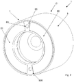
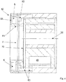
- reference number 1 denotes a mount for damping oscillations.
- Such mount 1 comprises a first chamber 40 deformable under the action of said oscillations.
- the mount 1 also comprises a second chamber 5; appropriately, also the second chamber 5 is at least in part deformable.
- the mount 1 further comprises a conduit 60 that sets the first and the second chamber 40, 5 into communication.
- the conduit 60 is a narrow passage that is interposed between the first and the second chamber 40, 5.
- the mount 1 comprises an incompressible fluid suitable for moving between the first and the second chamber 40, 5 through the conduit 60.
- the fluid is a magnetorheological fluid.
- a magnetorheological fluid is a material that displays a change in rheological behaviour following the application of a magnetic field. The application of a magnetic field and the intensity thereof are therefore able to substantially change, in a reversible way, the viscosity of a similar fluid (whereas the density is not changed).
- the mount 1 comprises a means 12 for exciting a magnetic field forexciting the magnetorheological fluid. It is part of the means 11 for regulating the dynamic behaviour of the mount 1 itself. Dynamic behaviour means the response of the mount 1 to the dynamic vibrations and stresses received. With a low energy value supplied, magnetorheological fluids allow a consistent variation in viscosity to be obtained; furthermore, the change in viscosity is almost instantaneous, in the order of a few milliseconds. The interesting aspect is that the change in the viscosity of the fluid determines a change in the response of the mount 1 to stresses while maintaining the geometry of the mount 1 unaltered.
- Figures 7 and 8 show the modulus and phase of the dynamic rigidity of the mount, respectively, as a function of the frequency of the stress; the curves indicated by reference “a” relate to a higher viscosity value, and the curves indicated by reference “b” relate to a lower viscosity value.
- magnetorheological fluids comprise ferromagnetic particles suspended in a carrier fluid, very often an organic solvent or water.
- the ferromagnetic nano-particles are coated by a surfactant to prevent them caking.
- a non-binding example of a magnetorheological fluid is MR Fluid MRF-132DG Lord Corporation.
- the means 12 for generating a magnetic field for exciting the magnetorheological fluid may comprise a first electromagnetic circuit. It therefore allows an active mount 1 to be obtained in which the response of the mount 1 can be modified as a function of the commands imparted by the means 12 for generating a magnetic field. Such commands could be imparted, for example, as a function of detections made by one or more sensors.
- the means 12 for generating a magnetic field for exciting the magnetorheological fluid comprises a first bobbin 121 that, in turn, comprises a plurality of turns.
- the first bobbin 121 also comprises a first insert 123 positioned at least partially within the turns.
- the first insert 123 is made of ferromagnetic material, preferably steel. Thanks to the magnetic permeability value of the first insert 123 it is possible to reach high magnetic field values with a low amperage value circulating within the first bobbin 121.
- the first bobbin 121 is external to the conduit 60.
- the first insert 123 is in contact with the fluid. Appropriately, the first insert 123 crosses a wall of the conduit 60 and projects internally to the conduit 60 to come into contact with the fluid.
- the first insert 123 skims the fluid along said conduit 60.
- the first insert 123 is positioned in a first zone of the conduit 60.
- the means 12 for generating a magnetic field for exciting the magnetorheological fluid comprises a second bobbin 122 that, in turn, comprises a plurality of turns and a second insert 124 positioned at least partially within the turns.
- the second insert 124 is ferromagnetic. It also skims the fluid along said conduit 60. The second insert 124 therefore comes into contact with the fluid.
- the conduit 60 comprises at least a wall with a first hole that is crossed by the first insert 123. At least at such first hole, the conduit 60 is made of diamagnetic or paramagnetic material.
- the second insert 124 crosses a wall that delimits the conduit 60 (advantageously, but not necessarily, the same wall crossed by the first insert 123).
- the conduit 60 comprises an annular component in which a groove is afforded in which the operating fluid flows (known in the technical sector as "inertia track").
- the first and/or the second inserts 123, 124 cross such component.
- the above-indicated measures allow the magnetic field to be concentrated. In proximity to the first insert 123 (and the second insert 124 and all the other inserts if present) the magnetorheological fluid becomes thicker, increasing the average viscosity value of the fluid and changing the dynamic behaviour of the hydraulic mounts.
- the generating means 12 is not explicitly illustrated, but has been omitted for simplicity (it could be positioned as in figure 1 or project outwards into the left part of figures 4 and 6 ).
- the mount 1 is advantageously a damping bushing 10.
- the bushing 10 comprises a first element 2 (which is a sleeve or a shaft), a second element 3 (which is a sleeve) enclosing the first element 2 and an elastomeric body 4 interposed between the first and the second element 2, 3.
- the elastomeric body 4 is radially interposed between the first and the second element 2, 3.
- the elastomeric body 4 is in contact both with the first and the second element 2, 3, It is advantageously made of rubber, preferably vulcanized.
- the elastomeric body 4 is in turn a hollow element that encloses the first element 2 about a longitudinal axis of the latter.
- the first and the second element 2, 3 have mutually parallel longitudinal axes of extension.
- the first and the second elements 2, 3 are advantageously made of metal material.
- the first chamber 40 is at least in part delimited by the elastomeric body 4.
- the first chamber 40 is defined by a concavity afforded internally to the elastomeric body 4.
- the first chamber 40 is defined by the combination of the elastomeric body 4 and the second element 3.
- the conduit 60 preferably extends according to a curved path.
- the conduit 60 optionally comprises at least one spiralling section. Appropriately the various turns are coplanar.
- the conduit comprises a labyrinth-shaped path in which several arches (in communication with one another) follow on inside one another.
- arches are concentric and/or coplanar.
- the second chamber 5 is not in contact with said elastomeric body 4.
- the second chamber 5 is delimited at least in part by a flexible membrane 50.
- the second chamber 5 is a flexible chamber in which the flexible membrane 50 moves to compensate the movement of the incompressible fluid.
- the second chamber 5 is annular.
- the second expansion chamber 5 encloses a compartment 7.
- the bushing 1 comprises a bottom 70 of such compartment 7 which is interposed between the compartment 7 itself and the elastomeric body 4. The bottom 70 therefore separates the compartment 7 and the elastomeric body 4.
- the flexible membrane 50 separates the second chamber 5 from an external zone to the bushing 1 in which there is air at atmospheric pressure.
- a hollow space 43 not affected by the incompressible fluid is interposed between the first and the second element 2, 3.
- the hollow space 43 is interposed between the elastomeric body 4 and the second element 3.
- the body 4 delimits the hollow space 43 at least in part.
- Such hollow space 43 is diametrically opposed to the first chamber 40 with respect to the first element 2.
- the elastomeric body 4 comprises a first portion 41 and a projection 42 that projects in a cantilever fashion towards the first portion 41.
- the first portion 41 extends perimetrally lying against the second element 3.
- the hollow space 43 extends between the first portion 41 and the projection 42.
- the hollow space 43 encloses the projection 42 on three sides.
- the first element 2 can be positioned eccentrically in the absence of external forces on the bushing 1.
- the first element 2 will have space to move upwards and will be able to do so without compressing the second chamber 5. This allows a soft bushing 10 to be obtained in static conditions. Once associated with the masses to be dampened, the first and the second element 2, 3 become coaxial (in static conditions).
- the radial movement of the second element 3 with respect to said first element 2 alternatively pumps the fluid from the first chamber 40 towards the second chamber 5 and recalls by depression the fluid from the second chamber 5 towards the first chamber 40.
- the second chamber 5 collects the incompressible fluid, but does not exert a pumping or suction force, or, even so, such action is certainly lower with respect to that of the first chamber 40.
- the fluid acts as a resonance element and allows an increase in rigidity at a predetermined frequency range of the oscillations to be dampened.
- the second chamber 5 extends radially between an internal annular edge 81 and an external annular edge 82.
- the bushing 1 comprises a metal flap 80 that extends radially and connects the internal annular edge 81 and the external annular edge 82.
- the flap 80 comprises a hole 83 for the introduction of the incompressible fluid into the second chamber 5.
- An obturator (preferably irremovable) obstructs the hole 83.
- a vacuum is first generated within the second chamber 5 and the first chamber 40. At this point, the incompressible fluid is introduced and then everything is closed (e.g. by forcing the obturator into the hole 83).
- the bushing 1 comprises an additional flexible membrane 51 that delimits the expansion chamber 5.
- the membrane 50 and the additional membrane 51 delimit a same face of the expansion chamber 5.
- the membrane 50 and the additional membrane 51 in the exemplified solution illustrated extend like two arches. They are separated by the flap 80 previously described and appropriately also by an additional flap 800. The membrane 50 and/or the additional membrane 51 are free to move according to the pressure in the expansion chamber 5.
- the elastomeric body 4 in that case delimits at least partially the first and the second chamber 40, 5.
- the first element 2 extends along a longitudinal axis 20.
- the bushing 10 along a direction identified by said longitudinal axis 20 extends between a first and a second end 21, 22.
- the minimum axial distance between the conduit 60 and the first end 21 is shorter by 1/5 of the length of the entire mount 1 measured along said longitudinal axis 20.
- the conduit 60 is therefore in proximity to an end of the first element 2 so as to be able to be easily accessible in order to facilitate the insertion of the magnetorheological fluid. Furthermore, this facilitates the housing of the means 12 for generating a magnetic field, minimizing its dimensions.
- the conduit 60 in the preferred solution is delimited by a plug 61 located at an axial end of the conduit 60.
- the plug 61 further comprises a hole for access to the inside of said conduit 60, said hole being occluded by an irremovable obturator. Such hole allows the suction of the air present in the conduit 60 and the introduction of the magnetorheological fluid.
- the invention as it is conceived enables achieving multiple advantages. First of all, it allows the active control of the mount as a function of specific commands from a control unit (e.g. a vehicle control unit). This allows active control that is variable over time, for adapting to specific situations.
- a control unit e.g. a vehicle control unit
- Acting on the viscosity of the fluid rather than on the inertia track 60 has the advantage of increasing the dynamic rigidity modulus without changing its shape and without varying the characteristic resonance frequency of the mount. Furthermore, in this way, the use of electromagnetic parts is avoided, with the advantage of increasing the strength of the final product.
Landscapes
- Engineering & Computer Science (AREA)
- General Engineering & Computer Science (AREA)
- Mechanical Engineering (AREA)
- Physics & Mathematics (AREA)
- Electromagnetism (AREA)
- Combined Devices Of Dampers And Springs (AREA)
- Registering, Tensioning, Guiding Webs, And Rollers Therefor (AREA)
- Vibration Prevention Devices (AREA)
- Control Of Motors That Do Not Use Commutators (AREA)
Claims (9)
- Support permettant d'amortir des oscillations, comprenant :- une première chambre (40) étant déformable sous l'action desdites oscillations ;- une seconde chambre (5) ;- un conduit (60) mettant en communication la première et la seconde chambre (40, 5) ;- un fluide incompressible adapté pour se déplacer entre la première et la seconde chambre (40, 5) à travers ledit conduit (60) ; ledit fluide étant un fluide magnétorhéologique ;ledit support (1) comprenant des moyens de réglage (11) pour régler le comportement dynamique du support et qui, à leur tour, comprennent des moyens (12) servant à générer un champ magnétique pour exciter le fluide magnétorhéologique ;
les moyens (12) servant à générer un champ magnétique pour exciter le fluide magnétorhéologique comprennent une première bobine (121) qui, à son tour, comprend une pluralité de spires ; la première bobine (121) comprenant aussi un premier insert ferromagnétique (123) positionné au moins partiellement à l'intérieur des spires ;
caractérisé en ce que la première bobine (121) est extérieure au conduit (60) ; le premier insert (123) traverse une paroi du conduit (60) et dépasse à l'intérieur du conduit (60) pour entrer en contact avec le fluide. - Support selon la revendication 1, caractérisé en ce que les moyens (12) servant à générer un champ magnétique pour exciter le fluide magnétorhéologique comprend une seconde bobine (122) extérieure au dit conduit (60) et comprenant à son tour :- une pluralité de spires ;- un second insert ferromagnétique (124) positionné au moins partiellement à l'intérieur des spires et qui écumera le fluide le long dudit conduit (60).
- Support selon l'une quelconque des revendications précédentes, caractérisé en ce que ledit conduit (60) est au moins partiellement constitué d'un matériau diamagnétique ou paramagnétique.
- Support selon l'une quelconque des revendications précédentes, caractérisé en ce que ledit conduit (60) est au moins partiellement constitué d'un matériau plastique ou d'un alliage d'aluminium.
- Support selon l'une quelconque des revendications précédentes, caractérisé en ce que le conduit (60) comprend au moins une paroi avec un premier orifice étant traversé par le premier insert (123) ; le conduit (60) est constitué d'un matériau diamagnétique ou paramagnétique, au moins en correspondance de ce premier orifice.
- Support selon l'une quelconque des revendications précédentes, caractérisé en ce qu'il s'agit d'une douille d'amortissement (10) comprenant un premier élément (2), un second élément (3) entourant le premier élément (2) et un corps élastomère (4) interposé entre le premier et le second élément (2, 3), ledit premier élément (2) étant un manchon ou un arbre, ledit second élément (3) étant un manchon ; ladite première chambre (40) étant au moins partiellement délimitée par ledit corps élastomère (4).
- Support selon la revendication 6, caractérisé en ce que la seconde chambre (5) est délimitée au moins partiellement par une membrane flexible (50) n'étant pas en contact avec ledit corps élastomère (4), un espace creux (43) non affecté par le fluide incompressible étant interposé entre le premier et le second élément (2, 3), ledit espace creux (43) étant diamétralement opposé à la première chambre (40) par rapport au premier élément (2) et, en l'absence de forces externes agissant sur la douille (10), le premier élément (2) étant excentré par rapport au second élément (3).
- Support selon la revendication 6, caractérisé en ce que ledit corps élastomère (4) délimite au moins partiellement la première et la seconde chambre (40, 5), la douille (10) se prolongeant le long d'un axe longitudinal (20) entre une première et une seconde extrémité (21, 22), et la distance minimale entre ledit conduit (60) et ladite première extrémité (21) étant inférieure à 1/5 de la longueur de la douille (10) entière telle que mesurée le long dudit axe longitudinal (20).
- Support selon la revendication 8, caractérisé en ce que ledit conduit (60) est au moins partiellement délimité par un bouchon (61) situé en correspondance de la première extrémité (21) et qui se prolonge transversalement au dit axe longitudinal (20), le bouchon (61) comprenant un orifice pour l'accès à l'intérieur dudit conduit (60), ledit orifice étant obturé par un obturateur inamovible.
Applications Claiming Priority (2)
| Application Number | Priority Date | Filing Date | Title |
|---|---|---|---|
| ITUA2016A004766A ITUA20164766A1 (it) | 2016-06-29 | 2016-06-29 | Supporto di smorzamento di oscillazioni |
| PCT/IB2017/053857 WO2018002833A1 (fr) | 2016-06-29 | 2017-06-28 | Support permettant d'amortir des oscillations |
Publications (2)
| Publication Number | Publication Date |
|---|---|
| EP3478986A1 EP3478986A1 (fr) | 2019-05-08 |
| EP3478986B1 true EP3478986B1 (fr) | 2020-04-29 |
Family
ID=57750460
Family Applications (1)
| Application Number | Title | Priority Date | Filing Date |
|---|---|---|---|
| EP17749520.7A Active EP3478986B1 (fr) | 2016-06-29 | 2017-06-28 | Support permettant d'amortir des oscillations |
Country Status (4)
| Country | Link |
|---|---|
| EP (1) | EP3478986B1 (fr) |
| IT (1) | ITUA20164766A1 (fr) |
| RU (1) | RU2737120C2 (fr) |
| WO (1) | WO2018002833A1 (fr) |
Families Citing this family (1)
| Publication number | Priority date | Publication date | Assignee | Title |
|---|---|---|---|---|
| CN117287421A (zh) * | 2023-10-30 | 2023-12-26 | 江苏毅合捷汽车科技股份有限公司 | 一种空压机消音装置及空压机 |
Family Cites Families (5)
| Publication number | Priority date | Publication date | Assignee | Title |
|---|---|---|---|---|
| JPS5965634A (ja) * | 1982-10-04 | 1984-04-13 | Honda Motor Co Ltd | 車両用エンジンマウント |
| JPH0450527A (ja) * | 1990-06-18 | 1992-02-19 | Nissan Motor Co Ltd | 車両用エンジン支持装置 |
| DE19961714C2 (de) * | 1999-12-21 | 2001-12-06 | Daimler Chrysler Ag | Feder-Dämpfersystem mit vorgeschaltetem Druckübersetzer |
| US6880483B2 (en) * | 2003-02-07 | 2005-04-19 | Delphi Technologies, Inc. | Active seat suspension for watercraft |
| DE10329982B4 (de) * | 2003-06-27 | 2005-09-15 | Siemens Ag | Vorrichtung zur Steuerung der Charakteristik eines Lagers mittels einer magnetisierbaren Flüssigkeit |
-
2016
- 2016-06-29 IT ITUA2016A004766A patent/ITUA20164766A1/it unknown
-
2017
- 2017-06-28 RU RU2019101680A patent/RU2737120C2/ru active
- 2017-06-28 WO PCT/IB2017/053857 patent/WO2018002833A1/fr not_active Ceased
- 2017-06-28 EP EP17749520.7A patent/EP3478986B1/fr active Active
Non-Patent Citations (1)
| Title |
|---|
| None * |
Also Published As
| Publication number | Publication date |
|---|---|
| RU2019101680A3 (fr) | 2020-07-29 |
| RU2737120C2 (ru) | 2020-11-24 |
| RU2019101680A (ru) | 2020-07-29 |
| EP3478986A1 (fr) | 2019-05-08 |
| WO2018002833A1 (fr) | 2018-01-04 |
| ITUA20164766A1 (it) | 2017-12-29 |
Similar Documents
| Publication | Publication Date | Title |
|---|---|---|
| US11280380B2 (en) | Magnetorheological hydraulic damper with passive damping chamber | |
| EP2710277B1 (fr) | Ensemble d'amortissement magnéto-rhéologique | |
| US11193532B2 (en) | Variable stiffness bushing | |
| CN113898693B (zh) | 减振执行器 | |
| EP1258650A3 (fr) | Support hydraulique à fluide magnétorhéologique | |
| US8672105B2 (en) | Damping control device filled with magnetorheological fluid and engine mount having the same | |
| US11465483B2 (en) | Variable stiffness vibration damping device | |
| CN101218450B (zh) | 磁流变流体装置、将该装置的气穴减到最少的方法以及铁路车辆悬挂系统 | |
| EP2291588B1 (fr) | Unité de suspension hydropneumatique | |
| US11371579B2 (en) | Variable stiffness bushing | |
| US11215260B2 (en) | Variable stiffness vibration damping device | |
| US20190017566A1 (en) | Clamped frequency dependent piston assembly | |
| US10605323B2 (en) | Elastomer bearing | |
| US20190242453A1 (en) | Damper device | |
| EP3478986B1 (fr) | Support permettant d'amortir des oscillations | |
| US10899215B2 (en) | Hydraulic mount apparatus | |
| JP2015102101A (ja) | 緩衝器 | |
| EP3620682A1 (fr) | Support de résonance magnétique comportant un découpleur en caoutchouc à double dureté | |
| CN111623077A (zh) | 变刚度减振装置 | |
| US9822839B2 (en) | Hydraulically damping rubber bearing | |
| JP2017078491A (ja) | 防振装置 | |
| EP3478987B1 (fr) | Bague d'amortissement | |
| US5839552A (en) | Method and apparatus for delivering fluid and or electric signals | |
| CN109083972B (zh) | 液压悬置装置 | |
| RU170565U1 (ru) | Амортизатор для гашения резонансных колебаний в вибрационных машинах |
Legal Events
| Date | Code | Title | Description |
|---|---|---|---|
| STAA | Information on the status of an ep patent application or granted ep patent |
Free format text: STATUS: UNKNOWN |
|
| STAA | Information on the status of an ep patent application or granted ep patent |
Free format text: STATUS: THE INTERNATIONAL PUBLICATION HAS BEEN MADE |
|
| PUAI | Public reference made under article 153(3) epc to a published international application that has entered the european phase |
Free format text: ORIGINAL CODE: 0009012 |
|
| STAA | Information on the status of an ep patent application or granted ep patent |
Free format text: STATUS: REQUEST FOR EXAMINATION WAS MADE |
|
| 17P | Request for examination filed |
Effective date: 20181130 |
|
| AK | Designated contracting states |
Kind code of ref document: A1 Designated state(s): AL AT BE BG CH CY CZ DE DK EE ES FI FR GB GR HR HU IE IS IT LI LT LU LV MC MK MT NL NO PL PT RO RS SE SI SK SM TR |
|
| AX | Request for extension of the european patent |
Extension state: BA ME |
|
| DAV | Request for validation of the european patent (deleted) | ||
| DAX | Request for extension of the european patent (deleted) | ||
| GRAP | Despatch of communication of intention to grant a patent |
Free format text: ORIGINAL CODE: EPIDOSNIGR1 |
|
| STAA | Information on the status of an ep patent application or granted ep patent |
Free format text: STATUS: GRANT OF PATENT IS INTENDED |
|
| GRAS | Grant fee paid |
Free format text: ORIGINAL CODE: EPIDOSNIGR3 |
|
| INTG | Intention to grant announced |
Effective date: 20200217 |
|
| GRAA | (expected) grant |
Free format text: ORIGINAL CODE: 0009210 |
|
| STAA | Information on the status of an ep patent application or granted ep patent |
Free format text: STATUS: THE PATENT HAS BEEN GRANTED |
|
| AK | Designated contracting states |
Kind code of ref document: B1 Designated state(s): AL AT BE BG CH CY CZ DE DK EE ES FI FR GB GR HR HU IE IS IT LI LT LU LV MC MK MT NL NO PL PT RO RS SE SI SK SM TR |
|
| REG | Reference to a national code |
Ref country code: GB Ref legal event code: FG4D |
|
| REG | Reference to a national code |
Ref country code: CH Ref legal event code: EP |
|
| REG | Reference to a national code |
Ref country code: AT Ref legal event code: REF Ref document number: 1263788 Country of ref document: AT Kind code of ref document: T Effective date: 20200515 |
|
| REG | Reference to a national code |
Ref country code: DE Ref legal event code: R096 Ref document number: 602017015794 Country of ref document: DE |
|
| REG | Reference to a national code |
Ref country code: IE Ref legal event code: FG4D |
|
| REG | Reference to a national code |
Ref country code: NL Ref legal event code: FP |
|
| REG | Reference to a national code |
Ref country code: LT Ref legal event code: MG4D |
|
| PG25 | Lapsed in a contracting state [announced via postgrant information from national office to epo] |
Ref country code: PT Free format text: LAPSE BECAUSE OF FAILURE TO SUBMIT A TRANSLATION OF THE DESCRIPTION OR TO PAY THE FEE WITHIN THE PRESCRIBED TIME-LIMIT Effective date: 20200831 Ref country code: IS Free format text: LAPSE BECAUSE OF FAILURE TO SUBMIT A TRANSLATION OF THE DESCRIPTION OR TO PAY THE FEE WITHIN THE PRESCRIBED TIME-LIMIT Effective date: 20200829 Ref country code: GR Free format text: LAPSE BECAUSE OF FAILURE TO SUBMIT A TRANSLATION OF THE DESCRIPTION OR TO PAY THE FEE WITHIN THE PRESCRIBED TIME-LIMIT Effective date: 20200730 Ref country code: NO Free format text: LAPSE BECAUSE OF FAILURE TO SUBMIT A TRANSLATION OF THE DESCRIPTION OR TO PAY THE FEE WITHIN THE PRESCRIBED TIME-LIMIT Effective date: 20200729 Ref country code: SE Free format text: LAPSE BECAUSE OF FAILURE TO SUBMIT A TRANSLATION OF THE DESCRIPTION OR TO PAY THE FEE WITHIN THE PRESCRIBED TIME-LIMIT Effective date: 20200429 Ref country code: FI Free format text: LAPSE BECAUSE OF FAILURE TO SUBMIT A TRANSLATION OF THE DESCRIPTION OR TO PAY THE FEE WITHIN THE PRESCRIBED TIME-LIMIT Effective date: 20200429 Ref country code: LT Free format text: LAPSE BECAUSE OF FAILURE TO SUBMIT A TRANSLATION OF THE DESCRIPTION OR TO PAY THE FEE WITHIN THE PRESCRIBED TIME-LIMIT Effective date: 20200429 |
|
| REG | Reference to a national code |
Ref country code: AT Ref legal event code: MK05 Ref document number: 1263788 Country of ref document: AT Kind code of ref document: T Effective date: 20200429 |
|
| PG25 | Lapsed in a contracting state [announced via postgrant information from national office to epo] |
Ref country code: BG Free format text: LAPSE BECAUSE OF FAILURE TO SUBMIT A TRANSLATION OF THE DESCRIPTION OR TO PAY THE FEE WITHIN THE PRESCRIBED TIME-LIMIT Effective date: 20200729 Ref country code: RS Free format text: LAPSE BECAUSE OF FAILURE TO SUBMIT A TRANSLATION OF THE DESCRIPTION OR TO PAY THE FEE WITHIN THE PRESCRIBED TIME-LIMIT Effective date: 20200429 Ref country code: LV Free format text: LAPSE BECAUSE OF FAILURE TO SUBMIT A TRANSLATION OF THE DESCRIPTION OR TO PAY THE FEE WITHIN THE PRESCRIBED TIME-LIMIT Effective date: 20200429 Ref country code: HR Free format text: LAPSE BECAUSE OF FAILURE TO SUBMIT A TRANSLATION OF THE DESCRIPTION OR TO PAY THE FEE WITHIN THE PRESCRIBED TIME-LIMIT Effective date: 20200429 |
|
| PG25 | Lapsed in a contracting state [announced via postgrant information from national office to epo] |
Ref country code: AL Free format text: LAPSE BECAUSE OF FAILURE TO SUBMIT A TRANSLATION OF THE DESCRIPTION OR TO PAY THE FEE WITHIN THE PRESCRIBED TIME-LIMIT Effective date: 20200429 |
|
| PG25 | Lapsed in a contracting state [announced via postgrant information from national office to epo] |
Ref country code: SM Free format text: LAPSE BECAUSE OF FAILURE TO SUBMIT A TRANSLATION OF THE DESCRIPTION OR TO PAY THE FEE WITHIN THE PRESCRIBED TIME-LIMIT Effective date: 20200429 Ref country code: EE Free format text: LAPSE BECAUSE OF FAILURE TO SUBMIT A TRANSLATION OF THE DESCRIPTION OR TO PAY THE FEE WITHIN THE PRESCRIBED TIME-LIMIT Effective date: 20200429 Ref country code: AT Free format text: LAPSE BECAUSE OF FAILURE TO SUBMIT A TRANSLATION OF THE DESCRIPTION OR TO PAY THE FEE WITHIN THE PRESCRIBED TIME-LIMIT Effective date: 20200429 Ref country code: DK Free format text: LAPSE BECAUSE OF FAILURE TO SUBMIT A TRANSLATION OF THE DESCRIPTION OR TO PAY THE FEE WITHIN THE PRESCRIBED TIME-LIMIT Effective date: 20200429 Ref country code: CZ Free format text: LAPSE BECAUSE OF FAILURE TO SUBMIT A TRANSLATION OF THE DESCRIPTION OR TO PAY THE FEE WITHIN THE PRESCRIBED TIME-LIMIT Effective date: 20200429 Ref country code: RO Free format text: LAPSE BECAUSE OF FAILURE TO SUBMIT A TRANSLATION OF THE DESCRIPTION OR TO PAY THE FEE WITHIN THE PRESCRIBED TIME-LIMIT Effective date: 20200429 Ref country code: MC Free format text: LAPSE BECAUSE OF FAILURE TO SUBMIT A TRANSLATION OF THE DESCRIPTION OR TO PAY THE FEE WITHIN THE PRESCRIBED TIME-LIMIT Effective date: 20200429 Ref country code: ES Free format text: LAPSE BECAUSE OF FAILURE TO SUBMIT A TRANSLATION OF THE DESCRIPTION OR TO PAY THE FEE WITHIN THE PRESCRIBED TIME-LIMIT Effective date: 20200429 |
|
| REG | Reference to a national code |
Ref country code: CH Ref legal event code: PL |
|
| REG | Reference to a national code |
Ref country code: DE Ref legal event code: R097 Ref document number: 602017015794 Country of ref document: DE |
|
| PG25 | Lapsed in a contracting state [announced via postgrant information from national office to epo] |
Ref country code: PL Free format text: LAPSE BECAUSE OF FAILURE TO SUBMIT A TRANSLATION OF THE DESCRIPTION OR TO PAY THE FEE WITHIN THE PRESCRIBED TIME-LIMIT Effective date: 20200429 Ref country code: SK Free format text: LAPSE BECAUSE OF FAILURE TO SUBMIT A TRANSLATION OF THE DESCRIPTION OR TO PAY THE FEE WITHIN THE PRESCRIBED TIME-LIMIT Effective date: 20200429 |
|
| PLBE | No opposition filed within time limit |
Free format text: ORIGINAL CODE: 0009261 |
|
| STAA | Information on the status of an ep patent application or granted ep patent |
Free format text: STATUS: NO OPPOSITION FILED WITHIN TIME LIMIT |
|
| PG25 | Lapsed in a contracting state [announced via postgrant information from national office to epo] |
Ref country code: LU Free format text: LAPSE BECAUSE OF NON-PAYMENT OF DUE FEES Effective date: 20200628 |
|
| 26N | No opposition filed |
Effective date: 20210201 |
|
| REG | Reference to a national code |
Ref country code: BE Ref legal event code: MM Effective date: 20200630 |
|
| PG25 | Lapsed in a contracting state [announced via postgrant information from national office to epo] |
Ref country code: IE Free format text: LAPSE BECAUSE OF NON-PAYMENT OF DUE FEES Effective date: 20200628 Ref country code: CH Free format text: LAPSE BECAUSE OF NON-PAYMENT OF DUE FEES Effective date: 20200630 Ref country code: LI Free format text: LAPSE BECAUSE OF NON-PAYMENT OF DUE FEES Effective date: 20200630 |
|
| PG25 | Lapsed in a contracting state [announced via postgrant information from national office to epo] |
Ref country code: BE Free format text: LAPSE BECAUSE OF NON-PAYMENT OF DUE FEES Effective date: 20200630 Ref country code: SI Free format text: LAPSE BECAUSE OF FAILURE TO SUBMIT A TRANSLATION OF THE DESCRIPTION OR TO PAY THE FEE WITHIN THE PRESCRIBED TIME-LIMIT Effective date: 20200429 |
|
| PG25 | Lapsed in a contracting state [announced via postgrant information from national office to epo] |
Ref country code: TR Free format text: LAPSE BECAUSE OF FAILURE TO SUBMIT A TRANSLATION OF THE DESCRIPTION OR TO PAY THE FEE WITHIN THE PRESCRIBED TIME-LIMIT Effective date: 20200429 Ref country code: MT Free format text: LAPSE BECAUSE OF FAILURE TO SUBMIT A TRANSLATION OF THE DESCRIPTION OR TO PAY THE FEE WITHIN THE PRESCRIBED TIME-LIMIT Effective date: 20200429 Ref country code: CY Free format text: LAPSE BECAUSE OF FAILURE TO SUBMIT A TRANSLATION OF THE DESCRIPTION OR TO PAY THE FEE WITHIN THE PRESCRIBED TIME-LIMIT Effective date: 20200429 |
|
| PG25 | Lapsed in a contracting state [announced via postgrant information from national office to epo] |
Ref country code: MK Free format text: LAPSE BECAUSE OF FAILURE TO SUBMIT A TRANSLATION OF THE DESCRIPTION OR TO PAY THE FEE WITHIN THE PRESCRIBED TIME-LIMIT Effective date: 20200429 |
|
| P01 | Opt-out of the competence of the unified patent court (upc) registered |
Effective date: 20230517 |
|
| PGFP | Annual fee paid to national office [announced via postgrant information from national office to epo] |
Ref country code: DE Payment date: 20250626 Year of fee payment: 9 |
|
| PGFP | Annual fee paid to national office [announced via postgrant information from national office to epo] |
Ref country code: GB Payment date: 20250619 Year of fee payment: 9 |
|
| PGFP | Annual fee paid to national office [announced via postgrant information from national office to epo] |
Ref country code: NL Payment date: 20250624 Year of fee payment: 9 |
|
| PGFP | Annual fee paid to national office [announced via postgrant information from national office to epo] |
Ref country code: FR Payment date: 20250624 Year of fee payment: 9 |
|
| PGFP | Annual fee paid to national office [announced via postgrant information from national office to epo] |
Ref country code: IT Payment date: 20250620 Year of fee payment: 9 |