EP3479090B1 - Système de mesure de température de fluide de traitement avec intrusion de processus améliorée - Google Patents
Système de mesure de température de fluide de traitement avec intrusion de processus améliorée Download PDFInfo
- Publication number
- EP3479090B1 EP3479090B1 EP17820891.4A EP17820891A EP3479090B1 EP 3479090 B1 EP3479090 B1 EP 3479090B1 EP 17820891 A EP17820891 A EP 17820891A EP 3479090 B1 EP3479090 B1 EP 3479090B1
- Authority
- EP
- European Patent Office
- Prior art keywords
- temperature
- process fluid
- thermowell
- thermal conductivity
- temperature sensitive
- Prior art date
- Legal status (The legal status is an assumption and is not a legal conclusion. Google has not performed a legal analysis and makes no representation as to the accuracy of the status listed.)
- Active
Links
Images



Classifications
-
- G—PHYSICS
- G01—MEASURING; TESTING
- G01N—INVESTIGATING OR ANALYSING MATERIALS BY DETERMINING THEIR CHEMICAL OR PHYSICAL PROPERTIES
- G01N25/00—Investigating or analyzing materials by the use of thermal means
- G01N25/18—Investigating or analyzing materials by the use of thermal means by investigating thermal conductivity
-
- G—PHYSICS
- G01—MEASURING; TESTING
- G01K—MEASURING TEMPERATURE; MEASURING QUANTITY OF HEAT; THERMALLY-SENSITIVE ELEMENTS NOT OTHERWISE PROVIDED FOR
- G01K1/00—Details of thermometers not specially adapted for particular types of thermometer
- G01K1/02—Means for indicating or recording specially adapted for thermometers
- G01K1/024—Means for indicating or recording specially adapted for thermometers for remote indication
-
- G—PHYSICS
- G01—MEASURING; TESTING
- G01K—MEASURING TEMPERATURE; MEASURING QUANTITY OF HEAT; THERMALLY-SENSITIVE ELEMENTS NOT OTHERWISE PROVIDED FOR
- G01K1/00—Details of thermometers not specially adapted for particular types of thermometer
- G01K1/08—Protective devices, e.g. casings
-
- G—PHYSICS
- G01—MEASURING; TESTING
- G01K—MEASURING TEMPERATURE; MEASURING QUANTITY OF HEAT; THERMALLY-SENSITIVE ELEMENTS NOT OTHERWISE PROVIDED FOR
- G01K1/00—Details of thermometers not specially adapted for particular types of thermometer
- G01K1/14—Supports; Fastening devices; Arrangements for mounting thermometers in particular locations
-
- G—PHYSICS
- G01—MEASURING; TESTING
- G01K—MEASURING TEMPERATURE; MEASURING QUANTITY OF HEAT; THERMALLY-SENSITIVE ELEMENTS NOT OTHERWISE PROVIDED FOR
- G01K13/00—Thermometers specially adapted for specific purposes
- G01K13/02—Thermometers specially adapted for specific purposes for measuring temperature of moving fluids or granular materials capable of flow
-
- G—PHYSICS
- G01—MEASURING; TESTING
- G01K—MEASURING TEMPERATURE; MEASURING QUANTITY OF HEAT; THERMALLY-SENSITIVE ELEMENTS NOT OTHERWISE PROVIDED FOR
- G01K17/00—Measuring quantity of heat
-
- G—PHYSICS
- G01—MEASURING; TESTING
- G01K—MEASURING TEMPERATURE; MEASURING QUANTITY OF HEAT; THERMALLY-SENSITIVE ELEMENTS NOT OTHERWISE PROVIDED FOR
- G01K17/00—Measuring quantity of heat
- G01K17/06—Measuring quantity of heat conveyed by flowing media, e.g. in heating systems e.g. the quantity of heat in a transporting medium, delivered to or consumed in an expenditure device
-
- G—PHYSICS
- G01—MEASURING; TESTING
- G01K—MEASURING TEMPERATURE; MEASURING QUANTITY OF HEAT; THERMALLY-SENSITIVE ELEMENTS NOT OTHERWISE PROVIDED FOR
- G01K7/00—Measuring temperature based on the use of electric or magnetic elements directly sensitive to heat ; Power supply therefor, e.g. using thermoelectric elements
- G01K7/42—Circuits effecting compensation of thermal inertia; Circuits for predicting the stationary value of a temperature
Definitions
- Process variables include pressure, temperature, flow, level, turbidity, density, concentration, chemical composition, and other properties.
- a process fluid temperature transmitter provides an output related to a process fluid temperature.
- the temperature transmitter output can be communicated over a process control loop to a control room, or the output can be communicated to another process device such that the process can be monitored and controlled.
- thermowells which thermally couple a temperature sensor to a process fluid, but otherwise protect and isolate the temperature sensor from direct contact with the process fluid.
- the thermowell is positioned within the process fluid in order to ensure substantial thermal contact between the process fluid and the temperature sensor disposed therein.
- thermowells are intrusive and invasive to the process fluid system. This is because the thermowell must extend through a wall of a process fluid conduit, such as a pipe, in order to couple a temperature sensor to the process fluid. Additionally, thermowells typically require regular evaluation for many related factors. Further, thermowells generally increase the response time for temperature measurement.
- the invention relates to a process fluid temperature measurement system according to claim 1, and a method for detecting process fluid temperature within a conduit according to claim 4.
- Embodiments of the invention are defined by the dependent claims.
- the temperature sensitive elements 304, 306 of sensor assembly 302 are generally coupled to transmitter circuitry 311 within transmitter housing 310.
- the transmitter circuitry (described below) is generally configured to measure or otherwise detect the electrical property of the temperature sensitive elements 304, 306 and generate a process fluid temperature output related to the measured temperatures.
- the output from process fluid temperature measurement system can be provided over a process communication loop, such as a 4-20 milliamp loop, or provided digitally, such as in accordance with the Highway Addressable Report Transducer (HART ® ).
- HART ® Highway Addressable Report Transducer
- Other examples of process communication protocols include the Profibus-PA Communication Protocol and the FOUNDATION TM Fieldbus Protocol.
- suitable wireless technologies can be used in addition to or in place of a wired process communication protocol.
- a suitable wireless process communication protocol is that in accordance with the WirelessHART standard (IEC 62591).
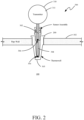
- temperature sensitive element 304 is disposed adjacent a distal end 305 of thermowell 200 and temperature sensitive element 306 is spaced apart from temperature sensitive element 304 along sensor assembly 302 by element 308 having a known or relatively constant thermal conductivity.
- electronics 311 within transmitter housing 310 can use a heat flux measurement to infer the temperature of process fluid 100.
- temperature sensitive elements 304, and 306 are separated in temperature capsule 302 by spacer 308 and placed at locations that are significantly impacted by both pipe wall temperature and process fluid temperature.
- a "spacer” is any physical structure or arrangement that controls or sets a distance and thermal conductivity between two elements.
- a spacer may be formed of a solid, a powder, such as Magnesium Oxide powder, or even an air gap. Any change on temperature sensor element 306 will also affect the temperature at temperature sensitive element 304 and vice versa. Given this correlation, the heat flux calculation can be simplified to what is shown in FIG. 3 . While FIG. 2 shows thermowell 200 extending into process fluid conduit 102, it is noted that heat flux measurement can be performed effectively for embodiments where the thermowell does not protrude into the process vessel or conduit whatsoever.
- FIG. 3 is a diagrammatic view of heat conduction modeled using resistive components.
- the heat of process fluid 100 shown at node 350, flows to node S2 at temperature sensitive element 304 through the thermal impedance of the thermowell as indicated diagrammatically at R twell 352.
- the heat flows along spacer element 308 to node S1 where the temperature is sensed by temperature sensitive element 306.
- the thermal impedance through spacer 308 is modeled diagrammatically as R snsr 354.
- heat at node S1 may flow to or from pipe wall 102 indicated at node 356.
- the thermal impedance from node S1 to pipe wall node 356 is illustrated diagrammatically as R adapter 358. Given these quantities, the temperature of process fluid is equal to the temperature measured at temperature sensitive element 304 plus the difference between the temperature measured at element 304 and 306 multiplied by R twell / R snsr .
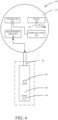
- FIG. 4 is a diagrammatic view of the process fluid temperature measurement system shown in FIGS. 2 and 3 .
- sensor assembly 302 includes temperature sensitive elements 304, 306 that are separated by spacer 308.
- Each of temperature sensitive elements 304, 306 is operably coupled to measurement circuitry 320 within transmitter housing 310.
- Measurement circuitry 320 generally includes any suitable arrangement of electrical circuits that are able to engage each of temperature sensitive elements 304 and 306 to measure the temperature-sensitive electrical property thereof.
- Measurement circuitry 320 can include one or more analog-to-digital converters as well as suitable switching circuitry, such as a multiplexer. Additionally, measurement circuitry 320 can also include any suitable linearization and/or amplification circuitry.
- Measurement circuitry 320 generally provides a digital indication of the electrical properties of temperature sensitive elements 304, 306 to controller 322.
- controller 322 may be a microprocessor or microcontroller, or any other suitable circuitry that is able to receive the digital indications from measurement circuity 320 and execute the heat flux calculation described with respect to FIG. 3 . Additionally, as shown in FIG. 4 , controller 322 is coupled to communication module 324.
- Process fluid temperature measurement system 300 also includes power supply module 326 that provides power to all components of the system as indicated at arrow 328.
- power module 326 may include suitable circuitry to condition power received from the loop to operate the various components of system 300.
- power supply module 326 may provide suitable power conditioning to allow the entire device to be powered by the loop to which it is coupled.
- power supply module 326 may include a source of power, such as a battery and suitable conditioning circuitry.
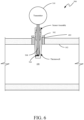
- FIG. 5 is a diagrammatic view of a process fluid temperature measurement system 390 in accordance with an embodiment of the present invention.
- a thermowell 400 is mounted to and extends through pipe wall 102 into process fluid 100.
- thermowell 400 does not extend into the process fluid conduit nearly as far as thermowell 104. Part of this difference is enabled by the thermal insulation that is provided by collar 402.
- Collar 402 is configured to engage an internal surface of aperture 106.
- collar 402 may include external threads that engage internal threads of aperture 106.
- Collar 402 then includes suitable internal structure to engage thermowell 400 to reliably and sealingly mount thermowell 400 to pipe wall 102.
- collar 402 is constructed from a material that reduces thermal conduction, in comparison to the material from which thermowell 400 is constructed. Using collar 402 around thermowell 400 allows the temperature from the process to propagate to the temperature sensor with reduced influence from conduit 102. By using a thermally resistive material between the stem of thermowell 400 and process conduit 102, the thermowell length can be reduced while still maintaining requisite measurement accuracy.
- the thermally-resistive material can be any suitable organic or inorganic material that is able to withstand the process fluid pressures involved, as well as provide suitable chemical resistance to the process fluid. Examples of suitable materials include ceramics as well as organic materials, such as polytetrafluoroethylene (PTFE).
- thermowell 400 By providing collar 402 around thermowell 400, thermowell 400 will respond faster with a reduced mass, which will also significantly reduce the need for wake frequency calculations. Further still, it is believed that fewer such "short" thermowell sizes will be needed, in comparison to current commercially-available sizes, which are generally specified down to the millimeter. Additionally, a thermally-insulative material, such as a gasket, may also be disposed between a mounting flange of the thermowell and a pipe standoff.
- a thermally-insulative material such as a gasket
- FIG. 6 is a diagrammatic view of a process fluid temperature measurement system in accordance with an embodiment of the present invention.
- Process fluid temperature measurement system 500 bears many similarities to system 390 (described with respect to FIG. 5 ), and like components are numbered similarly.
- the main difference between system 500 and system 390 is that system 500 has a sensor assembly that has a single temperature sensitive element 304.
- a thermally-insulative collar such as collar 402
- enough heat flow to/from the process fluid conduit may be prevented that a short (with respect to thermowell 104) thermowell may be used.
- thermowell 400 is described as a thermally insulative collar, this description is merely in comparison to the material of thermowell 400. Thus, as long as the thermal conductivity of collar 402 is lower than that of thermowell 400, collar 402 maybe considered to be thermally insulative. Further still, it is expressly contemplated that the thermowell itself could be designed with a different alloy on the process conduit side that has a higher thermal impedance.
- the hot end of the thermal well stem can be highly thermally conductive in order to propagate heat from the process fluid to the sensor element.
- a flange of the thermowell could be constructed using a relatively low thermal conductance that is attached to the thermowell stem having a higher thermal conductance in order to achieve the thermal isolation described herein.
Landscapes
- Physics & Mathematics (AREA)
- General Physics & Mathematics (AREA)
- Chemical & Material Sciences (AREA)
- Combustion & Propulsion (AREA)
- Engineering & Computer Science (AREA)
- Biochemistry (AREA)
- Analytical Chemistry (AREA)
- General Health & Medical Sciences (AREA)
- Immunology (AREA)
- Pathology (AREA)
- Life Sciences & Earth Sciences (AREA)
- Health & Medical Sciences (AREA)
- Measuring Temperature Or Quantity Of Heat (AREA)
Claims (7)
- Système de mesurage de température de fluide de traitement (390, 500) comprenant :un collier thermo-isolant (402) configuré pour être couplé à une paroi de conduit de fluide de traitement (102) ;un thermopuits (104, 200, 400) configuré être couplé à un conduit de fluide de traitement via le collier thermo-isolant et pour s'étendre à travers la paroi de conduit de fluide de traitement (102) ;un assemblage de capteur de température (110) disposé à l'intérieur du thermopuits (104, 200, 400), l'assemblage de détection de température incluant :un premier élément de détection de température (304) disposé à l'intérieur du thermopuits (104, 200, 400) de manière adjacente à une extrémité distale du thermopuits (104, 200, 400) ;un distanceur (308) ayant une conductivité thermique connue, le distanceur (308) étant formé d'une poudre ;un second élément de détection de température (306) à distance du premier élément de détection de température (304) le long du distanceur (308) ; etun circuit de transmission (311) couplé au premier et au second élément de détection de température (304, 306) et configuré pour effectuer un calcul de flux thermique pour fournir une sortie de température de fluide de traitement,dans lequel le second élément de détection de température (306) est disposé à l'intérieur du thermopuits (104, 200, 400),dans lequel le calcul de flux thermique est basé sur la conductivité thermique de l'extrémité distale du thermopuits (104, 200, 400) et sur la conductivité thermique du distanceur (308) entre le premier et le second élément de détection de température (304, 306),dans lequel le calcul de flux thermique est basé sur un ratio de la conductivité thermique de l'extrémité distale du thermopuits (104, 200, 400) sur la conductivité thermique du distanceur (308),dans lequel la sortie de température de fluide de traitement est égale à la température mesurée par le premier élément de détection de température (304) ajoutée à une quantité qui est une différence de mesurages entre le premier et le second élément de détection de température (304, 306) multipliée par le ratio,dans lequel le circuit de transmission (310, 311, 324) inclut un microprocesseur (322) configuré pour effectuer le mesurage de flux thermique, etdans lequel le circuit de transmission (310, 311, 324) inclut un circuit de communication configuré pour communiquer la sortie de température de fluide de traitement à un dispositif à distance.
- Système de mesurage de température de fluide de traitement selon la revendication 1, dans lequel la poudre est de l'oxyde de magnésium.
- Système de mesurage de température de fluide de traitement selon la revendication 1, dans lequel le collier thermo-isolant a des pas de vis internes configurés pour engager le thermopuits et des pas de vis externes configurés pour engager la paroi de conduit, et dans lequel le collier thermo-isolant a une conductivité thermique qui est à inférieure à la conductivité thermique du thermopuits.
- Procédé de détection d'une température de fluide de traitement à l'intérieur d'un conduit, le procédé comprenant les étapes consistant à :coupler un thermopuits (104, 200, 400) via une paroi du conduit (102), dans lequel le couplage du thermopuits (104, 200, 400) via la paroi de conduit (102) inclut de coupler un collier thermo-isolant (402) à la paroi de conduit et de coupler le thermopuits (104, 200, 400) au collier thermo-isolant (402) ;détecter une première température (S1) en utilisant un premier élément de détection de température (304) à une position à l'intérieur du thermopuits (104, 200, 400), dans lequel le premier élément de détection de température (304) détecte la première température relativement à une extrémité distale (305) du thermopuits ;détecter une seconde température (S2) en utilisant un second élément de détection de température (306) à une position à l'intérieur du thermopuits qui est à distance du premier élément de détection de température (304) par l'intermédiaire d'un distanceur (308) ayant une conductivité thermique connue, le distanceur (308) étant formé d'une poudre, la détection de la première température (S1) et de la seconde température (S2) étant effectuée en utilisant un circuit de mesurage (320) d'un transmetteur de température de fluide de traitement ; eteffectuer un calcul de flux thermique en utilisant la première et la seconde température détectées (S1, S2) pour fournir une sortie de température de fluide de traitement ;dans lequel le calcul de flux thermique est basé sur la conductivité thermique de l'extrémité distale (305) du thermopuits et sur la conductivité thermique de distanceur (308) entre le premier et le second élément de détection de température (304, 306),dans lequel le calcul de flux thermique est basé sur un ratio de la conductivité thermique de l'extrémité distale (305) du thermopuits sur la conductivité thermique du distanceur (308),dans lequel la sortie de température de fluide de traitement est égale à la température mesurée par le premier élément de détection de température (304) ajoutée à une quantité qui est une différence de mesurage entre le premier et le second élément de détection de température (304, 308) multipliée par le ratio,dans lequel l'étape consistant à effectuer le calcul de flux thermique est exécutée par un microprocesseur du transmetteur de température de fluide de traitement, etdans lequel la sortie de température de fluide de traitement est fournie en accord avec un protocole de communication de traitement en utilisant un circuit de communication (310, 311, 324) du transmetteur de température de fluide de traitement.
- Procédé selon la revendication 4, dans lequel la poudre est de l'oxyde de magnésium.
- Procédé selon la revendication 4, dans lequel la sortie de température de fluide de traitement est fournie par le biais d'un canal de communication de traitement filaire.
- Procédé selon la revendication 4, dans lequel la sortie de température de fluide de traitement est fournie de manière non filaire.
Applications Claiming Priority (2)
| Application Number | Priority Date | Filing Date | Title |
|---|---|---|---|
| US15/196,569 US11067520B2 (en) | 2016-06-29 | 2016-06-29 | Process fluid temperature measurement system with improved process intrusion |
| PCT/US2017/037222 WO2018005082A1 (fr) | 2016-06-29 | 2017-06-13 | Système de mesure de température de fluide de traitement avec intrusion de processus améliorée |
Publications (3)
| Publication Number | Publication Date |
|---|---|
| EP3479090A1 EP3479090A1 (fr) | 2019-05-08 |
| EP3479090A4 EP3479090A4 (fr) | 2020-02-19 |
| EP3479090B1 true EP3479090B1 (fr) | 2024-12-11 |
Family
ID=60313735
Family Applications (1)
| Application Number | Title | Priority Date | Filing Date |
|---|---|---|---|
| EP17820891.4A Active EP3479090B1 (fr) | 2016-06-29 | 2017-06-13 | Système de mesure de température de fluide de traitement avec intrusion de processus améliorée |
Country Status (7)
| Country | Link |
|---|---|
| US (1) | US11067520B2 (fr) |
| EP (1) | EP3479090B1 (fr) |
| JP (1) | JP7005531B2 (fr) |
| CN (2) | CN206656811U (fr) |
| CA (1) | CA3029201A1 (fr) |
| RU (1) | RU2710520C1 (fr) |
| WO (1) | WO2018005082A1 (fr) |
Families Citing this family (23)
| Publication number | Priority date | Publication date | Assignee | Title |
|---|---|---|---|---|
| US11067520B2 (en) * | 2016-06-29 | 2021-07-20 | Rosemount Inc. | Process fluid temperature measurement system with improved process intrusion |
| EP3379238A1 (fr) * | 2017-03-20 | 2018-09-26 | F. Hoffmann-La Roche AG | Dispositif permettant de détecter et d'enregistrer une température d'un fluide lorsqu'il est placé dans le fluide |
| CA3088739A1 (fr) | 2018-01-18 | 2019-07-25 | In-Situ, Inc. | Capteurs de temperature a reponse rapide |
| US10976204B2 (en) * | 2018-03-07 | 2021-04-13 | Rosemount Inc. | Heat flux sensor with improved heat transfer |
| US11029215B2 (en) * | 2018-09-24 | 2021-06-08 | Rosemount Inc. | Low contact clamp for non-invasive process fluid temperature indication |
| US11073429B2 (en) * | 2018-09-24 | 2021-07-27 | Rosemount Inc. | Non-invasive process fluid temperature indication for high temperature applications |
| EP3857189B1 (fr) | 2018-09-28 | 2025-01-15 | Rosemount Inc. | Indication de température de fluide de traitement non invasive à erreur réduite |
| US20200103293A1 (en) | 2018-09-28 | 2020-04-02 | Rosemount Inc. | Non-invasive process fluid temperature indication |
| US11002582B2 (en) * | 2018-09-28 | 2021-05-11 | Rosemount Inc. | Process transmitter with thermal fluid detection for decreasing damage to the process transmitter components |
| CH715585B1 (de) | 2018-11-23 | 2021-12-30 | Belimo Holding Ag | Regelventil. |
| CN109443444B (zh) * | 2018-12-17 | 2020-03-31 | 西安交通大学 | 利用流型和温度测量装置预测管路内凝结水击的方法 |
| CN113993425B (zh) * | 2019-06-27 | 2024-05-28 | 布瑞威利私人有限公司 | 温度传感器配件 |
| CA3142176C (fr) | 2019-07-01 | 2023-02-07 | Thermasense Corp. | Appareil, systemes et procedes d'interrogation thermique non invasive |
| US11022321B1 (en) | 2019-12-16 | 2021-06-01 | June Life, Inc. | Cooking appliance accessory and method of use |
| JP6716799B1 (ja) * | 2020-02-07 | 2020-07-01 | 三菱日立パワーシステムズ株式会社 | 温度計保護筒、温度計測器具及び蒸気配管構造物並びに温度計保護筒の設置方法 |
| WO2021207976A1 (fr) * | 2020-04-15 | 2021-10-21 | Rosemount Inc. | Ensemble de détection de température résistant aux vibrations |
| USD978600S1 (en) | 2021-06-11 | 2023-02-21 | June Life, Inc. | Cooking vessel |
| USD1007224S1 (en) | 2021-06-11 | 2023-12-12 | June Life, Inc. | Cooking vessel |
| WO2022272021A1 (fr) | 2021-06-25 | 2022-12-29 | Rosemount Inc. | Système d'estimation de température de fluide de traitement à base de flux de chaleur avec amélioration de la réponse en temps thermique |
| EP4130694B1 (fr) * | 2021-08-02 | 2025-10-15 | Abb Schweiz Ag | Ensemble capteur de température |
| US12072245B2 (en) * | 2021-09-30 | 2024-08-27 | Rosemount Inc. | Heat flux temperature sensor probe for non-invasive process fluid temperature applications |
| CN113820044B (zh) * | 2021-11-25 | 2022-03-01 | 东营昱辰技术有限公司 | 一种防止水锤冲击的温度变送器 |
| CN114136477B (zh) * | 2021-11-29 | 2023-02-24 | 盐城市苏瑞思电子有限责任公司 | 一种基于铂热电阻的温度传感装置 |
Citations (1)
| Publication number | Priority date | Publication date | Assignee | Title |
|---|---|---|---|---|
| US20150253205A1 (en) * | 2014-03-04 | 2015-09-10 | Walter Hauser | Measuring device and measuring method for registering an ambient temperature of a medical machine, and device and method for medical insufflation |
Family Cites Families (54)
| Publication number | Priority date | Publication date | Assignee | Title |
|---|---|---|---|---|
| US3724267A (en) | 1970-08-28 | 1973-04-03 | Foster Wheeler Corp | Heat flux sensing device |
| DE2500034C3 (de) | 1975-01-02 | 1980-10-02 | Bruno 8031 Puchheim Gruber | Transformator mit einem einteiligen, hochspannungsfesten Isolierkörper und Verfahren zu seiner Herstellung |
| FR2382000A1 (fr) | 1977-02-25 | 1978-09-22 | Auxitrol | Rampe thermocouples pour la mesure de la moyenne de plusieurs temperatures |
| US4384793A (en) | 1980-12-22 | 1983-05-24 | Uop Inc. | Temperature profile monitoring method and apparatus |
| US4436438A (en) | 1981-07-21 | 1984-03-13 | Wahl Instruments, Inc. | Multiple probe temperature measuring system and probes therefor |
| US4467134A (en) * | 1983-06-30 | 1984-08-21 | General Electric Company | Thermocouple with out-of-line aspiration holes |
| IT1164309B (it) | 1983-07-07 | 1987-04-08 | Cise Spa | Gruppo strumentato per il rilievo delle temperature e dei flussi termici in pareti evaporative di generatori di vapore |
| US4488516A (en) | 1983-11-18 | 1984-12-18 | Combustion Engineering, Inc. | Soot blower system |
| US4722610A (en) | 1986-03-07 | 1988-02-02 | Technology For Energy Corporation | Monitor for deposition on heat transfer surfaces |
| US4826540A (en) | 1987-01-12 | 1989-05-02 | Sam Mele | Adjustable depth thermocouple system |
| US5064604A (en) | 1990-02-07 | 1991-11-12 | Westinghouse Electric Corp. | Cost effective fluid line status sensor system |
| GB9005286D0 (en) | 1990-03-09 | 1990-05-02 | Avon Rubber Plc | Thermal sensing |
| DE4101549A1 (de) | 1991-01-21 | 1992-07-23 | Klaus Fischer Mess Und Regelte | Vorrichtung zum messen von temperaturen in rohrleitungen |
| US5743646A (en) | 1996-07-01 | 1998-04-28 | General Motors Corporation | Temperature sensor with improved thermal barrier and gas seal between the probe and housing |
| US6503221B1 (en) | 1997-06-12 | 2003-01-07 | Abbott Laboratories | Temperature compensation system for regulating flow through tubing in a pump |
| US6390670B1 (en) * | 1999-08-06 | 2002-05-21 | Pgi International Ltd. | Temperature sensing device for metering fluids |
| DE19939757A1 (de) * | 1999-08-21 | 2001-02-22 | Temperaturmestechnik Geraberg | Verfahren und Temperaturfühler zur Medientemperaturerfassung |
| US6485174B1 (en) | 2000-10-27 | 2002-11-26 | The Babcock & Wilcox Company | Attachable heat flux measuring device |
| CN2513092Y (zh) * | 2001-11-23 | 2002-09-25 | 魏东 | 高压流体精确测温装置 |
| US6944394B2 (en) * | 2002-01-22 | 2005-09-13 | Watlow Electric Manufacturing Company | Rapid response electric heat exchanger |
| FR2840986B1 (fr) | 2002-06-12 | 2004-09-10 | Eric Esprimont | Methode mettant en oeuvre des capteurs de flux de chaleur pour evaluer la puissance d'une reaction thermique a l'interieur d'une enceinte, et dispositif pour la mise en oeuvre d'une telle methode |
| US6824305B1 (en) | 2002-08-16 | 2004-11-30 | The Texas A & M University System | Local wall heat flux/temperature meter for convective flow and method of utilizing same |
| US7249885B2 (en) | 2002-10-16 | 2007-07-31 | Clyde Bergemann Gmbh | Heat flux measuring device for pressure pipes, method for producing a measuring device, method for monitoring an operating state of a heat exchanger, heat exchanger and method for measuring a heat flux |
| US6848373B2 (en) | 2003-02-21 | 2005-02-01 | Breen Energy Solutions | Method of monitoring heat flux and controlling corrosion of furnace wall tubes |
| JP4041018B2 (ja) * | 2003-06-25 | 2008-01-30 | Tdk株式会社 | 温度センサ |
| US20050209813A1 (en) | 2004-03-16 | 2005-09-22 | Johnson Controls Technology Company | Temperature sensing device |
| US7156552B2 (en) | 2004-09-07 | 2007-01-02 | University Corporation For Atmospheric Research | Temperature sensor system for mobile platforms |
| JP4600170B2 (ja) | 2004-09-15 | 2010-12-15 | セイコーエプソン株式会社 | 体温計、および体温計を有する電子機器 |
| RU2281466C1 (ru) * | 2004-12-06 | 2006-08-10 | Закрытое акционерное общество Промышленная группа "Метран" | Датчик температуры |
| US9184364B2 (en) | 2005-03-02 | 2015-11-10 | Rosemount Inc. | Pipeline thermoelectric generator assembly |
| GB0508584D0 (en) | 2005-04-28 | 2005-06-01 | Boiler Man Systems Internation | A pipe assembly |
| US7484886B2 (en) | 2006-05-03 | 2009-02-03 | International Business Machines Corporation | Bolometric on-chip temperature sensor |
| DE102007002369B3 (de) | 2007-01-17 | 2008-05-15 | Drägerwerk AG & Co. KGaA | Doppeltemperatursensor |
| KR101365879B1 (ko) | 2007-04-04 | 2014-02-21 | 에스펙 가부시키가이샤 | 습도계 및 노점계 |
| JP5085398B2 (ja) * | 2007-04-16 | 2012-11-28 | 株式会社デンソー | 温度センサ |
| KR101125432B1 (ko) | 2007-06-19 | 2012-03-27 | 가부시키가이샤 무라타 세이사쿠쇼 | 리드선 부착 온도 센서 |
| US8280674B2 (en) | 2008-01-24 | 2012-10-02 | Raytheon Company | Apparatus for measuring surface temperature using embedded components |
| CN201221986Y (zh) * | 2008-06-02 | 2009-04-15 | 昆明理工大学 | 一种测量管内高压流体温度的装置 |
| DE102008026642B4 (de) | 2008-06-03 | 2010-06-10 | Dräger Medical AG & Co. KG | Doppeltemperatursensor mit einem Aufnahmeelement |
| RU2373502C1 (ru) * | 2008-08-05 | 2009-11-20 | Закрытое Акционерное общество "ТЭРИФ-Н" | Устройство для измерения температуры теплоносителя |
| DE102009009592A1 (de) | 2009-02-19 | 2010-08-26 | Clyde Bergemann Gmbh Maschinen- Und Apparatebau | Messeinrichtung für einen Wärmetauscher |
| US8118484B2 (en) | 2009-03-31 | 2012-02-21 | Rosemount Inc. | Thermocouple temperature sensor with connection detection circuitry |
| US8529126B2 (en) | 2009-06-11 | 2013-09-10 | Rosemount Inc. | Online calibration of a temperature measurement point |
| DE102010030076A1 (de) * | 2010-06-15 | 2011-12-15 | Robert Bosch Gmbh | Vorrichtung zur Erfassung einer Temperatur eines strömenden fluiden Mediums |
| US8308349B1 (en) | 2010-11-08 | 2012-11-13 | Murray F Feller | Asymmetric heat flux sensor with in-situ drift compensation |
| CN201852643U (zh) * | 2010-11-16 | 2011-06-01 | 李世强 | 温度计盲肠 |
| JP2012112767A (ja) | 2010-11-24 | 2012-06-14 | Citizen Holdings Co Ltd | 温度測定装置 |
| RU2450250C1 (ru) * | 2011-04-04 | 2012-05-10 | Яков Серафимович Кожевников | Устройство для измерения температуры теплоносителя и беспроводной измеритель температуры |
| GB2500034A (en) * | 2012-03-07 | 2013-09-11 | Passivsystems Ltd | Calculation of temperature on a remote side of a barrier using thermal conductivity properties of the barrier and temperature measurements |
| US9188490B2 (en) | 2013-03-12 | 2015-11-17 | Rosemount Inc. | Thermowell insert |
| JP5677519B2 (ja) * | 2013-07-01 | 2015-02-25 | 株式会社村田製作所 | 温度検出装置 |
| US8851744B1 (en) * | 2013-10-02 | 2014-10-07 | Onicon, Inc. | Calibration apparatus and method for heat transfer measurement |
| US9360377B2 (en) | 2013-12-26 | 2016-06-07 | Rosemount Inc. | Non-intrusive temperature measurement assembly |
| US11067520B2 (en) * | 2016-06-29 | 2021-07-20 | Rosemount Inc. | Process fluid temperature measurement system with improved process intrusion |
-
2016
- 2016-06-29 US US15/196,569 patent/US11067520B2/en active Active
-
2017
- 2017-01-23 CN CN201720091539.1U patent/CN206656811U/zh not_active Withdrawn - After Issue
- 2017-01-23 CN CN201710049532.8A patent/CN107543625B/zh active Active
- 2017-06-13 CA CA3029201A patent/CA3029201A1/fr not_active Abandoned
- 2017-06-13 EP EP17820891.4A patent/EP3479090B1/fr active Active
- 2017-06-13 JP JP2018565387A patent/JP7005531B2/ja active Active
- 2017-06-13 WO PCT/US2017/037222 patent/WO2018005082A1/fr not_active Ceased
- 2017-06-13 RU RU2019102184A patent/RU2710520C1/ru active
Patent Citations (1)
| Publication number | Priority date | Publication date | Assignee | Title |
|---|---|---|---|---|
| US20150253205A1 (en) * | 2014-03-04 | 2015-09-10 | Walter Hauser | Measuring device and measuring method for registering an ambient temperature of a medical machine, and device and method for medical insufflation |
Also Published As
| Publication number | Publication date |
|---|---|
| CN206656811U (zh) | 2017-11-21 |
| US20180003655A1 (en) | 2018-01-04 |
| CN107543625A (zh) | 2018-01-05 |
| EP3479090A1 (fr) | 2019-05-08 |
| JP7005531B2 (ja) | 2022-01-21 |
| WO2018005082A1 (fr) | 2018-01-04 |
| RU2710520C1 (ru) | 2019-12-26 |
| CA3029201A1 (fr) | 2018-01-04 |
| CN107543625B (zh) | 2021-08-06 |
| US11067520B2 (en) | 2021-07-20 |
| JP2019519779A (ja) | 2019-07-11 |
| EP3479090A4 (fr) | 2020-02-19 |
Similar Documents
| Publication | Publication Date | Title |
|---|---|---|
| US11067520B2 (en) | Process fluid temperature measurement system with improved process intrusion | |
| US11630072B2 (en) | Non-intrusive process fluid temperature calculation system | |
| CN209945581U (zh) | 过程流体温度估测系统 | |
| RU2344391C2 (ru) | Узел высокотемпературного датчика давления | |
| JP5184506B2 (ja) | 高温圧力トランスミッタアセンブリ | |
| JP7343576B2 (ja) | 非侵襲的プロセス流体温度指示 | |
| EP4078119B1 (fr) | Indication d'écoulement de fluide de traitement non invasive à l'aide d'une différence de température |
Legal Events
| Date | Code | Title | Description |
|---|---|---|---|
| STAA | Information on the status of an ep patent application or granted ep patent |
Free format text: STATUS: THE INTERNATIONAL PUBLICATION HAS BEEN MADE |
|
| PUAI | Public reference made under article 153(3) epc to a published international application that has entered the european phase |
Free format text: ORIGINAL CODE: 0009012 |
|
| STAA | Information on the status of an ep patent application or granted ep patent |
Free format text: STATUS: REQUEST FOR EXAMINATION WAS MADE |
|
| 17P | Request for examination filed |
Effective date: 20181210 |
|
| AK | Designated contracting states |
Kind code of ref document: A1 Designated state(s): AL AT BE BG CH CY CZ DE DK EE ES FI FR GB GR HR HU IE IS IT LI LT LU LV MC MK MT NL NO PL PT RO RS SE SI SK SM TR |
|
| AX | Request for extension of the european patent |
Extension state: BA ME |
|
| DAV | Request for validation of the european patent (deleted) | ||
| DAX | Request for extension of the european patent (deleted) | ||
| A4 | Supplementary search report drawn up and despatched |
Effective date: 20200116 |
|
| RIC1 | Information provided on ipc code assigned before grant |
Ipc: G01K 7/42 20060101ALI20200110BHEP Ipc: G01K 13/02 20060101AFI20200110BHEP Ipc: G01K 1/08 20060101ALI20200110BHEP |
|
| RIN1 | Information on inventor provided before grant (corrected) |
Inventor name: RUD, JASON Inventor name: TRIMBLE, STEVEN |
|
| STAA | Information on the status of an ep patent application or granted ep patent |
Free format text: STATUS: EXAMINATION IS IN PROGRESS |
|
| 17Q | First examination report despatched |
Effective date: 20211119 |
|
| REG | Reference to a national code |
Ipc: G01K0001024000 Ref country code: DE Ref legal event code: R079 Ref document number: 602017086729 Country of ref document: DE Free format text: PREVIOUS MAIN CLASS: G01K0013020000 Ipc: G01K0001024000 |
|
| GRAP | Despatch of communication of intention to grant a patent |
Free format text: ORIGINAL CODE: EPIDOSNIGR1 |
|
| GRAP | Despatch of communication of intention to grant a patent |
Free format text: ORIGINAL CODE: EPIDOSNIGR1 |
|
| STAA | Information on the status of an ep patent application or granted ep patent |
Free format text: STATUS: GRANT OF PATENT IS INTENDED |
|
| RIC1 | Information provided on ipc code assigned before grant |
Ipc: G01K 13/02 20060101ALI20240517BHEP Ipc: G01K 1/08 20060101ALI20240517BHEP Ipc: G01K 7/42 20060101ALI20240517BHEP Ipc: G01N 25/18 20060101ALI20240517BHEP Ipc: G01K 17/00 20060101ALI20240517BHEP Ipc: G01K 1/024 20210101AFI20240517BHEP |
|
| INTG | Intention to grant announced |
Effective date: 20240614 |
|
| GRAJ | Information related to disapproval of communication of intention to grant by the applicant or resumption of examination proceedings by the epo deleted |
Free format text: ORIGINAL CODE: EPIDOSDIGR1 |
|
| STAA | Information on the status of an ep patent application or granted ep patent |
Free format text: STATUS: EXAMINATION IS IN PROGRESS |
|
| GRAP | Despatch of communication of intention to grant a patent |
Free format text: ORIGINAL CODE: EPIDOSNIGR1 |
|
| STAA | Information on the status of an ep patent application or granted ep patent |
Free format text: STATUS: GRANT OF PATENT IS INTENDED |
|
| INTC | Intention to grant announced (deleted) | ||
| INTG | Intention to grant announced |
Effective date: 20240828 |
|
| GRAS | Grant fee paid |
Free format text: ORIGINAL CODE: EPIDOSNIGR3 |
|
| GRAA | (expected) grant |
Free format text: ORIGINAL CODE: 0009210 |
|
| STAA | Information on the status of an ep patent application or granted ep patent |
Free format text: STATUS: THE PATENT HAS BEEN GRANTED |
|
| P01 | Opt-out of the competence of the unified patent court (upc) registered |
Free format text: CASE NUMBER: APP_56066/2024 Effective date: 20241014 |
|
| AK | Designated contracting states |
Kind code of ref document: B1 Designated state(s): AL AT BE BG CH CY CZ DE DK EE ES FI FR GB GR HR HU IE IS IT LI LT LU LV MC MK MT NL NO PL PT RO RS SE SI SK SM TR |
|
| REG | Reference to a national code |
Ref country code: GB Ref legal event code: FG4D |
|
| REG | Reference to a national code |
Ref country code: CH Ref legal event code: EP |
|
| REG | Reference to a national code |
Ref country code: IE Ref legal event code: FG4D |
|
| REG | Reference to a national code |
Ref country code: DE Ref legal event code: R096 Ref document number: 602017086729 Country of ref document: DE |
|
| REG | Reference to a national code |
Ref country code: LT Ref legal event code: MG9D |
|
| PG25 | Lapsed in a contracting state [announced via postgrant information from national office to epo] |
Ref country code: HR Free format text: LAPSE BECAUSE OF FAILURE TO SUBMIT A TRANSLATION OF THE DESCRIPTION OR TO PAY THE FEE WITHIN THE PRESCRIBED TIME-LIMIT Effective date: 20241211 |
|
| PG25 | Lapsed in a contracting state [announced via postgrant information from national office to epo] |
Ref country code: FI Free format text: LAPSE BECAUSE OF FAILURE TO SUBMIT A TRANSLATION OF THE DESCRIPTION OR TO PAY THE FEE WITHIN THE PRESCRIBED TIME-LIMIT Effective date: 20241211 |
|
| PG25 | Lapsed in a contracting state [announced via postgrant information from national office to epo] |
Ref country code: BG Free format text: LAPSE BECAUSE OF FAILURE TO SUBMIT A TRANSLATION OF THE DESCRIPTION OR TO PAY THE FEE WITHIN THE PRESCRIBED TIME-LIMIT Effective date: 20241211 |
|
| REG | Reference to a national code |
Ref country code: NL Ref legal event code: MP Effective date: 20241211 |
|
| PG25 | Lapsed in a contracting state [announced via postgrant information from national office to epo] |
Ref country code: ES Free format text: LAPSE BECAUSE OF FAILURE TO SUBMIT A TRANSLATION OF THE DESCRIPTION OR TO PAY THE FEE WITHIN THE PRESCRIBED TIME-LIMIT Effective date: 20241211 |
|
| PG25 | Lapsed in a contracting state [announced via postgrant information from national office to epo] |
Ref country code: NO Free format text: LAPSE BECAUSE OF FAILURE TO SUBMIT A TRANSLATION OF THE DESCRIPTION OR TO PAY THE FEE WITHIN THE PRESCRIBED TIME-LIMIT Effective date: 20250311 |
|
| PG25 | Lapsed in a contracting state [announced via postgrant information from national office to epo] |
Ref country code: LV Free format text: LAPSE BECAUSE OF FAILURE TO SUBMIT A TRANSLATION OF THE DESCRIPTION OR TO PAY THE FEE WITHIN THE PRESCRIBED TIME-LIMIT Effective date: 20241211 Ref country code: GR Free format text: LAPSE BECAUSE OF FAILURE TO SUBMIT A TRANSLATION OF THE DESCRIPTION OR TO PAY THE FEE WITHIN THE PRESCRIBED TIME-LIMIT Effective date: 20250312 |
|
| PG25 | Lapsed in a contracting state [announced via postgrant information from national office to epo] |
Ref country code: RS Free format text: LAPSE BECAUSE OF FAILURE TO SUBMIT A TRANSLATION OF THE DESCRIPTION OR TO PAY THE FEE WITHIN THE PRESCRIBED TIME-LIMIT Effective date: 20250311 |
|
| PG25 | Lapsed in a contracting state [announced via postgrant information from national office to epo] |
Ref country code: NL Free format text: LAPSE BECAUSE OF FAILURE TO SUBMIT A TRANSLATION OF THE DESCRIPTION OR TO PAY THE FEE WITHIN THE PRESCRIBED TIME-LIMIT Effective date: 20241211 |
|
| REG | Reference to a national code |
Ref country code: AT Ref legal event code: MK05 Ref document number: 1750713 Country of ref document: AT Kind code of ref document: T Effective date: 20241211 |
|
| PG25 | Lapsed in a contracting state [announced via postgrant information from national office to epo] |
Ref country code: SM Free format text: LAPSE BECAUSE OF FAILURE TO SUBMIT A TRANSLATION OF THE DESCRIPTION OR TO PAY THE FEE WITHIN THE PRESCRIBED TIME-LIMIT Effective date: 20241211 |
|
| PG25 | Lapsed in a contracting state [announced via postgrant information from national office to epo] |
Ref country code: PL Free format text: LAPSE BECAUSE OF FAILURE TO SUBMIT A TRANSLATION OF THE DESCRIPTION OR TO PAY THE FEE WITHIN THE PRESCRIBED TIME-LIMIT Effective date: 20241211 |
|
| PGFP | Annual fee paid to national office [announced via postgrant information from national office to epo] |
Ref country code: DE Payment date: 20250520 Year of fee payment: 9 |
|
| PGFP | Annual fee paid to national office [announced via postgrant information from national office to epo] |
Ref country code: GB Payment date: 20250520 Year of fee payment: 9 |
|
| PG25 | Lapsed in a contracting state [announced via postgrant information from national office to epo] |
Ref country code: IS Free format text: LAPSE BECAUSE OF FAILURE TO SUBMIT A TRANSLATION OF THE DESCRIPTION OR TO PAY THE FEE WITHIN THE PRESCRIBED TIME-LIMIT Effective date: 20250411 |
|
| PG25 | Lapsed in a contracting state [announced via postgrant information from national office to epo] |
Ref country code: PT Free format text: LAPSE BECAUSE OF FAILURE TO SUBMIT A TRANSLATION OF THE DESCRIPTION OR TO PAY THE FEE WITHIN THE PRESCRIBED TIME-LIMIT Effective date: 20250411 |
|
| PG25 | Lapsed in a contracting state [announced via postgrant information from national office to epo] |
Ref country code: EE Free format text: LAPSE BECAUSE OF FAILURE TO SUBMIT A TRANSLATION OF THE DESCRIPTION OR TO PAY THE FEE WITHIN THE PRESCRIBED TIME-LIMIT Effective date: 20241211 |
|
| PG25 | Lapsed in a contracting state [announced via postgrant information from national office to epo] |
Ref country code: RO Free format text: LAPSE BECAUSE OF FAILURE TO SUBMIT A TRANSLATION OF THE DESCRIPTION OR TO PAY THE FEE WITHIN THE PRESCRIBED TIME-LIMIT Effective date: 20241211 Ref country code: AT Free format text: LAPSE BECAUSE OF FAILURE TO SUBMIT A TRANSLATION OF THE DESCRIPTION OR TO PAY THE FEE WITHIN THE PRESCRIBED TIME-LIMIT Effective date: 20241211 |
|
| PG25 | Lapsed in a contracting state [announced via postgrant information from national office to epo] |
Ref country code: SK Free format text: LAPSE BECAUSE OF FAILURE TO SUBMIT A TRANSLATION OF THE DESCRIPTION OR TO PAY THE FEE WITHIN THE PRESCRIBED TIME-LIMIT Effective date: 20241211 |
|
| PG25 | Lapsed in a contracting state [announced via postgrant information from national office to epo] |
Ref country code: CZ Free format text: LAPSE BECAUSE OF FAILURE TO SUBMIT A TRANSLATION OF THE DESCRIPTION OR TO PAY THE FEE WITHIN THE PRESCRIBED TIME-LIMIT Effective date: 20241211 |
|
| PG25 | Lapsed in a contracting state [announced via postgrant information from national office to epo] |
Ref country code: IT Free format text: LAPSE BECAUSE OF FAILURE TO SUBMIT A TRANSLATION OF THE DESCRIPTION OR TO PAY THE FEE WITHIN THE PRESCRIBED TIME-LIMIT Effective date: 20241211 |
|
| PG25 | Lapsed in a contracting state [announced via postgrant information from national office to epo] |
Ref country code: SE Free format text: LAPSE BECAUSE OF FAILURE TO SUBMIT A TRANSLATION OF THE DESCRIPTION OR TO PAY THE FEE WITHIN THE PRESCRIBED TIME-LIMIT Effective date: 20241211 |
|
| REG | Reference to a national code |
Ref country code: DE Ref legal event code: R097 Ref document number: 602017086729 Country of ref document: DE |
|
| PG25 | Lapsed in a contracting state [announced via postgrant information from national office to epo] |
Ref country code: DK Free format text: LAPSE BECAUSE OF FAILURE TO SUBMIT A TRANSLATION OF THE DESCRIPTION OR TO PAY THE FEE WITHIN THE PRESCRIBED TIME-LIMIT Effective date: 20241211 |
|
| PLBE | No opposition filed within time limit |
Free format text: ORIGINAL CODE: 0009261 |
|
| STAA | Information on the status of an ep patent application or granted ep patent |
Free format text: STATUS: NO OPPOSITION FILED WITHIN TIME LIMIT |
|
| REG | Reference to a national code |
Ref country code: CH Ref legal event code: L10 Free format text: ST27 STATUS EVENT CODE: U-0-0-L10-L00 (AS PROVIDED BY THE NATIONAL OFFICE) Effective date: 20251022 |
|
| 26N | No opposition filed |
Effective date: 20250912 |
|
| REG | Reference to a national code |
Ref country code: CH Ref legal event code: H13 Free format text: ST27 STATUS EVENT CODE: U-0-0-H10-H13 (AS PROVIDED BY THE NATIONAL OFFICE) Effective date: 20260127 |
|
| PG25 | Lapsed in a contracting state [announced via postgrant information from national office to epo] |
Ref country code: MC Free format text: LAPSE BECAUSE OF FAILURE TO SUBMIT A TRANSLATION OF THE DESCRIPTION OR TO PAY THE FEE WITHIN THE PRESCRIBED TIME-LIMIT Effective date: 20241211 |
|
| PG25 | Lapsed in a contracting state [announced via postgrant information from national office to epo] |
Ref country code: LU Free format text: LAPSE BECAUSE OF NON-PAYMENT OF DUE FEES Effective date: 20250613 |
|
| REG | Reference to a national code |
Ref country code: BE Ref legal event code: MM Effective date: 20250630 |
|
| PG25 | Lapsed in a contracting state [announced via postgrant information from national office to epo] |
Ref country code: IE Free format text: LAPSE BECAUSE OF NON-PAYMENT OF DUE FEES Effective date: 20250613 |
|
| PG25 | Lapsed in a contracting state [announced via postgrant information from national office to epo] |
Ref country code: BE Free format text: LAPSE BECAUSE OF NON-PAYMENT OF DUE FEES Effective date: 20250630 |
|
| PG25 | Lapsed in a contracting state [announced via postgrant information from national office to epo] |
Ref country code: FR Free format text: LAPSE BECAUSE OF NON-PAYMENT OF DUE FEES Effective date: 20250630 |
|
| PG25 | Lapsed in a contracting state [announced via postgrant information from national office to epo] |
Ref country code: CH Free format text: LAPSE BECAUSE OF NON-PAYMENT OF DUE FEES Effective date: 20250630 |