EP3479095B1 - Vorrichtung und verfahren zur prüfung eines asphaltprüflings - Google Patents
Vorrichtung und verfahren zur prüfung eines asphaltprüflings Download PDFInfo
- Publication number
- EP3479095B1 EP3479095B1 EP17820611.6A EP17820611A EP3479095B1 EP 3479095 B1 EP3479095 B1 EP 3479095B1 EP 17820611 A EP17820611 A EP 17820611A EP 3479095 B1 EP3479095 B1 EP 3479095B1
- Authority
- EP
- European Patent Office
- Prior art keywords
- specimen
- deformation
- lateral
- support member
- lateral direction
- Prior art date
- Legal status (The legal status is an assumption and is not a legal conclusion. Google has not performed a legal analysis and makes no representation as to the accuracy of the status listed.)
- Not-in-force
Links
Images









Classifications
-
- G—PHYSICS
- G01—MEASURING; TESTING
- G01N—INVESTIGATING OR ANALYSING MATERIALS BY DETERMINING THEIR CHEMICAL OR PHYSICAL PROPERTIES
- G01N3/00—Investigating strength properties of solid materials by application of mechanical stress
- G01N3/32—Investigating strength properties of solid materials by application of mechanical stress by applying repeated or pulsating forces
- G01N3/34—Investigating strength properties of solid materials by application of mechanical stress by applying repeated or pulsating forces generated by mechanical means, e.g. hammer blows
-
- G—PHYSICS
- G01—MEASURING; TESTING
- G01N—INVESTIGATING OR ANALYSING MATERIALS BY DETERMINING THEIR CHEMICAL OR PHYSICAL PROPERTIES
- G01N33/00—Investigating or analysing materials by specific methods not covered by groups G01N1/00 - G01N31/00
- G01N33/42—Road-making materials
-
- G—PHYSICS
- G01—MEASURING; TESTING
- G01N—INVESTIGATING OR ANALYSING MATERIALS BY DETERMINING THEIR CHEMICAL OR PHYSICAL PROPERTIES
- G01N19/00—Investigating materials by mechanical methods
-
- G—PHYSICS
- G01—MEASURING; TESTING
- G01N—INVESTIGATING OR ANALYSING MATERIALS BY DETERMINING THEIR CHEMICAL OR PHYSICAL PROPERTIES
- G01N3/00—Investigating strength properties of solid materials by application of mechanical stress
- G01N3/56—Investigating resistance to wear or abrasion
-
- E—FIXED CONSTRUCTIONS
- E01—CONSTRUCTION OF ROADS, RAILWAYS, OR BRIDGES
- E01C—CONSTRUCTION OF, OR SURFACES FOR, ROADS, SPORTS GROUNDS, OR THE LIKE; MACHINES OR AUXILIARY TOOLS FOR CONSTRUCTION OR REPAIR
- E01C7/00—Coherent pavings made in situ
- E01C7/08—Coherent pavings made in situ made of road-metal and binders
- E01C7/10—Coherent pavings made in situ made of road-metal and binders of road-metal and cement or like binders
- E01C7/14—Concrete paving
-
- Y—GENERAL TAGGING OF NEW TECHNOLOGICAL DEVELOPMENTS; GENERAL TAGGING OF CROSS-SECTIONAL TECHNOLOGIES SPANNING OVER SEVERAL SECTIONS OF THE IPC; TECHNICAL SUBJECTS COVERED BY FORMER USPC CROSS-REFERENCE ART COLLECTIONS [XRACs] AND DIGESTS
- Y02—TECHNOLOGIES OR APPLICATIONS FOR MITIGATION OR ADAPTATION AGAINST CLIMATE CHANGE
- Y02A—TECHNOLOGIES FOR ADAPTATION TO CLIMATE CHANGE
- Y02A30/00—Adapting or protecting infrastructure or their operation
- Y02A30/30—Adapting or protecting infrastructure or their operation in transportation, e.g. on roads, waterways or railways
Definitions
- This invention relates to an apparatus and method for testing a pavement specimen.
- the invention relates to an apparatus and method for testing the susceptibility of a pavement specimen to rutting.
- Rutting is classified as one of the primary structural deteriorations criteria in flexible pavements design [ reference 1 ].
- the distress can be divided principally into three mechanisms; one dimensional deformation, mechanical deformation and lateral flow or plastic movement.
- Plastic deformation is the major type of permanent deformation caused by inadequate shear strength. Severe rutting is a result of this mechanism [reference 2].
- SPT Simple Performance Test
- Asphalt material response under repeated load application results in a permanent deformation curve that can be divided into three major zones known as primary, secondary and tertiary zones.
- permanent deformation accumulates at a decreasing rate in the primary zone.
- the rate of decrease reaches a constant value in the secondary zone and increases rapidly at the onset of the tertiary zone [ reference 4].
- the inflection point between the secondary and tertiary zones is referred to as the flow number on the deformation vs number of cycle curve or the flow time on the deformation vs time relationship.
- the tertiary inflection point has two significant characteristics. First, permanent deformation rate undergoes a dramatic increase after the tertiary inflection point. Second, it occurs under a constant volume which indicates pure shear (plastic) deformation.
- SPT tests have several disadvantages. They are time consuming and they require elaborate testing equipment. In addition, they are not suitable for quality control and quality assurance (QC/QA). A major disadvantage is that none of the test loading sequences is close to the actual traffic loading. As a result, other types of test apparatuses have been developed with less sophisticated test mechanisms which better represent actual traffic loading that can be used for QC/QA of pavement construction [reference 5].
- a test that can be used to better simulate the action of moving traffic wheel is the wheel tracker test [ references 6 and 7 ].
- Figure 1 illustrates a conventional wheel tracker test setup.
- An asphalt specimen 101 is held in a specimen holder 103 on a moving table that reciprocates beneath a vertically loaded wheel 102.
- the specimen is fully constrained by the specimen holder by fixed supports 110, 111, 120, 121 at all four sides of the specimen; that is, the specimen is fully constrained.
- the vertical displacement of the specimen is measured as the rut depth develops in the specimen.
- the test ends either when a maximum number of cycles is reached or when a maximum rut depth is reached, whichever occurs first.
- Table 1 shows the results of conventional wheel tracker tests conducted by the inventor using the apparatus of figure 1 .
- Six specimens were prepared with different binder types (60/70 and 80/100), different aggregate gradations (maximum nominal sizes, 14 mm and 20 mm), and different air voids content (ranging from 4.3% to 7.7%).
- the tests were conducted at high temperatures (either 50°C or 60°C) for 50,000 cycles and the total permanent vertical deformations were recorded.
- Table 1 shows that the total permanent deformations accumulated after 50,000 cycles at 50°C and 60°C are quite small and not significantly different regardless of the aggregate gradation, binder type or test temperature. Therefore, the tertiary stage for rutting is unlikely to be reached using the conventional fully constrained test setup.
- the wheel tracker test results for the fully constrained specimens are difficult to analyse as the differences in rutting depth between the specimens are so small that it is not possible to accurately rank the permanent deformation resistance of the tested mixes.
- JP H10 185908 (Nikken KK) describes a reciprocal wheel rutting test.
- CN 201 402 236 Y (Univ South China Tech) describes a rutting test, in which the specimen is supported from beneath.
- An object of at least preferred embodiments of the present invention is to provide a rut testing apparatus and/or method that better simulates actual constraining stresses and is capable of determining tertiary zone shear failure. It is an additional or alternative object of at least preferred embodiments of the present invention to at least provide the public with a useful choice.
- a rut testing apparatus for testing the susceptibility of a pavement specimen to rutting, the apparatus comprising: a specimen holder for supporting the specimen to be tested, the specimen holder arranged to support the specimen from below and to support two opposite ends of the specimen, the specimen holder arranged so that one or more lateral sides of the specimen are substantially unsupported or supported by a moveable support member to allow the specimen to deform in a lateral direction that is transverse to a direction that extends between the opposite ends for substantially an entire test; a wheel that is arranged to move along at least part of the specimen in the direction that extends between the opposite ends; and a sensor to determine deformation of the specimen in the lateral direction.
- the specimen holder is arranged so that two lateral sides of the specimen are substantially unsupported during testing.
- the lateral sides may be parallel to the direction of movement of the wheel, or may be offset from parallel.
- the specimen, and specimen holder may be any suitable shape, such as square, rectangular, circular, or any other suitable shape.
- the specimen holder comprises a first moveable support member to support a first lateral side of the specimen, the first movable support member arranged to allow deformation of the specimen in the lateral direction.
- the specimen holder comprises a fixed support member to support a second opposite lateral side of the specimen.
- the specimen holder comprises a second moveable support member to support a second opposite lateral side of the specimen, the second moveable support member arranged to allow deformation of the specimen in the lateral direction.
- the apparatus comprises a second sensor associated with the second lateral side to determine deformation of the specimen in the lateral direction.
- At least one sensor comprises a dial test indicator.
- At least one sensor comprises a linear variable differential transformer.
- the specimen holder comprises a first end moveable support member to support a first end of the specimen, the first end moveable support member arranged to allow deformation of the specimen in the direction that extends between the opposite ends.
- the specimen holder comprises a fixed end support member to support a second opposite end of the specimen.
- the specimen holder may comprise a second end moveable support member to support a second opposite end of the specimen, the second end moveable support member arranged to allow deformation of the specimen in the direction that extends between the opposite ends.
- the position of the moveable support member(s) is controlled to provide substantially constant pressure to the sides and/or ends of the specimen during testing.
- the apparatus comprises a sensor to determine deformation of the specimen in a direction that is generally orthogonal to the direction that extends between the opposite ends and to the lateral direction; i.e. a generally downwards direction.
- the sensor comprises a linear variable differential transformer.
- the apparatus comprises a processor configured to provide a graphical representation of deformation in the lateral direction and/or in a direction that is generally orthogonal to the direction that extends between the opposite ends and to the lateral direction (i.e. in a downward direction).
- the graphical representation shows the rate of change of permanent deformation in the lateral direction.
- the graphical representation shows the rate of change of permanent deformation in the direction that is generally orthogonal to the direction that extends between the opposite ends and to the lateral direction; i.e. downward vertical deformation if a base of the specimen holder that supports the specimen from below is horizontal.
- the graphical representation shows the number of cycles at which permanent deformation in both directions progresses at the same rate.
- the apparatus comprises a processor configured to determine the extent of deformation in the lateral direction and/or in a direction that is generally orthogonal to the direction that extends between the opposite ends and to the lateral direction.
- the processor is configured to determine the rate of change of permanent deformation in the lateral direction.
- the processor is configured to determine the rate of change of permanent deformation in the direction that is generally orthogonal to the direction that extends between the opposite ends and to the lateral direction; i.e. a downward direction.
- the processor is configured to determine the number of cycles at which permanent deformation in both directions progresses at the same rate.
- the processor is configured to determine or estimate permanent deformation in the direction that is generally orthogonal to the direction that extends between the opposite ends and to the lateral direction, based on the determined permanent deformation in the lateral direction.
- the lateral direction is substantially orthogonal to the direction that extends between the opposite ends.
- the apparatus may comprise a temperature controlled environment for the specimen.
- the temperature controlled environment may comprise a temperature cabinet.
- a method of testing the susceptibility of a pavement specimen to rutting comprising: supporting a pavement specimen in a specimen holder, the specimen holder arranged to support the specimen from below and to support two opposite ends of the specimen, the specimen holder arranged so that one or more lateral sides of the specimen are substantially unsupported or supported bv a moveable support member to allow the specimen to deform in a lateral direction that is transverse to a direction that extends between the opposite ends for substantially an entire test; moving a wheel along at least part of the specimen in the direction that extends between the opposite ends; and measuring deformation of the specimen in the lateral direction.
- said supporting a pavement specimen comprises having two lateral sides of the specimen substantially unsupported.
- the method comprises supporting a first lateral side of the specimen with a first moveable support member, wherein the first movable support member is arranged to allow deformation of the specimen in the lateral direction.
- the method comprises supporting a second opposite lateral side of the specimen with a fixed support member.
- the method comprises supporting a second opposite lateral side of the specimen with a second moveable support member, wherein the second moveable support member is arranged to allow deformation of the specimen in the lateral direction.
- the method comprises measuring the lateral deformation of the lateral side(s) of the specimen with a dial test indicator.
- the method comprises measuring the lateral deformation of the lateral side(s) of the specimen with a linear variable differential transformer.
- the method comprises supporting a first end of the specimen with a first end moveable support member, the first end moveable support member arranged to allow deformation of the specimen in the direction that extends between the opposite ends.
- the method comprises supporting a second opposite end of the specimen with a fixed end support member.
- the method may comprise supporting a second opposite end of the specimen with a second end moveable support member, the second end moveable support member arranged to allow deformation of the specimen in the direction that extends between the opposite ends.
- the method comprises controlling the position of the moveable support member(s) to provide substantially constant pressure to the sides and/or ends of the specimen during testing.
- the method comprises measuring deformation of the specimen in a direction that is generally orthogonal to the direction that extends between the opposite ends and to the lateral direction; i.e. a downward direction. In an embodiment, the method comprises measuring deformation of the specimen with a linear variable differential transformer.
- the method comprises using a processor to provide a graphical representation of deformation in the lateral direction and/or in a direction that is generally orthogonal to the direction that extends between the opposite ends and to the lateral direction (i.e. in a downward direction).
- the graphical representation shows the rate of change of permanent deformation in the lateral direction. In an embodiment, the graphical representation shows the rate of change of permanent deformation in the direction that is generally orthogonal to the direction that extends between the opposite ends and to the lateral direction.
- the graphical representation shows the number of cycles at which permanent deformation in both directions progresses at the same rate.
- the method comprises using a processor to determine the extent of deformation in the lateral direction and/or in a direction that is generally orthogonal to the direction that extends between the opposite ends and to the lateral direction.
- the processor is configured to determine the rate of change of permanent deformation in the lateral direction.
- the processor is configured to determine the rate of change of permanent deformation in the direction that is generally orthogonal to the direction that extends between the opposite ends and to the lateral direction.
- the processor is configured to determine the number of cycles at which permanent deformation in both directions progresses at the same rate.
- the method comprises determining or estimating permanent deformation in the direction that is generally orthogonal to the direction that extends between the opposite ends and to the lateral direction, based on the determined permanent deformation in the lateral direction.
- the method comprises the lateral direction is substantially orthogonal to the direction that extends between the opposite ends.
- the method comprises placing the specimen in a temperature controlled environment for the test.
- the temperature controlled environment may comprise a temperature cabinet.
- the method is performed using an apparatus as outlined in relation to the first aspect above.
- 'and/or' means 'and' or 'or', or where the context allows both.
- a component may be, but is not limited to being, a process running on a processor, a processor, an object, an executable, a thread of execution, a program, and/or a computer.
- an application running on a controller and the controller can be a component.
- One or more components may reside within a process and/or thread of execution and a component may be localized on one computer and/or distributed between two or more computers.
- connection to' as used in this specification in relation to data or signal transfer includes all direct or indirect types of communication, including wired and wireless, via a cellular network, via a data bus, or any other computer structure. It is envisaged that they may be intervening elements between the connected integers. Variants such as 'in communication with', 'joined to', and 'attached to' are to be interpreted in a similar manner. Related terms such as 'connecting' and 'in connection with' are to be interpreted in the same manner.
- the pavement specimen is partially constrained in the specimen holder.
- One or more lateral sides of the partially constrained specimen are either substantially unsupported, or supported by a moveable support member.
- one or more ends of the partially constrained specimen are supported by a moveable support member.
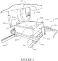
- Figures 2 and 3 show a rut testing apparatus 200 in accordance with a first embodiment for testing the susceptibility of a pavement specimen 201 to permanent deformation (rutting).
- the apparatus comprises a specimen holder 203 for supporting the specimen 201 to be tested, a wheel 202, a first lateral displacement sensor 230, a second lateral displacement sensor 231 and a vertical displacement sensor 232.
- the specimen holder 203 has a base plate 203a that is arranged to support the specimen 201 from below.
- the base plate 203a is advantageously at least the size of the specimen to support the underside of the entire specimen.
- the specimen 201 rests on the base plate 203a during testing.
- the specimen holder has two end support members 220, 221 in the form of laterally extending plates that are arranged to support two opposite ends of the specimen. In the form shown, the end support members 220, 221 are fixed in position relative to the base plate 203a by upstands that are coupled to the base plate. Alternatively, the end support members 220 could be integrally formed with the base plate 203a.
- the specimen holder is arranged so that two lateral sides 210, 211 of the specimen 201 are substantially unsupported (other than by the base plate 203a) during testing.
- the specimen holder 203 is arranged to allow the specimen 201 to deform in a second lateral direction LD that is transverse to a first direction FD that extends between the end support members 220, 221 that support opposite ends of the specimen.
- the lateral direction LD is substantially orthogonal to the first direction FD, but that will depend on the shape of the specimen.
- the specimen holder 203 is arranged to allow the specimen 201 to deform in the lateral direction LD for substantially the entire test. In an embodiment, the specimen holder 203 is arranged to allow the specimen 201 to deform in the lateral direction LD for the entire test.
- the specimen holder is positioned on a table 204 that is slidably mounted on rails 205.
- the table, and thereby the specimen holder 203, is driven to reciprocate back and forth on the rails 205 by a suitable driving device such as hydraulic ram(s) or motor(s) for example.
- the specimen holder components can be made from any suitable material that is compatible with the specimen being tested, such as stainless steel for example.
- the wheel 202 is rotatable around a rotation axis 202a.
- the wheel comprises a suitable resilient peripheral material such as rubber for example, to enable the wheel to apply load to the specimen 201 while not causing excessive damage to the specimen.
- the peripheral material on the wheel is chosen to be representative of a vehicle tyre on a road.
- the wheel is movable in a direction that is orthogonal to a plane that contains the lateral direction LD and the first direction FD (i.e. vertically), with its position and downward force that is applied to the specimen being controlled by a hydraulic ram or other movement device.
- the wheel 202 is arranged to move along at least part of the specimen 201 in the first direction FD that extends between the opposite ends of the specimen.
- the movement of the wheel 202 along the specimen 201 occurs as a result of the reciprocation of the table 204 on the rails.
- the wheel 202 is arranged to move along substantially the entire length of the specimen in the first direction FD, with the end support members 220, 221 arranged to prevent crumbling of the ends of the specimen under the load of the wheel.
- the specimen holder 203 and table 204 may be fixed, with the reciprocating movement of the wheel 202 along at least part of the specimen occurring as a result of movement of the wheel 202 rather than movement of the table 204.
- the wheel is configured to move at a relatively slow speed of around 26.4 cycles per minute (0.44 Hz). This is representative of vehicle movement at intersections where rutting is prone to occur.
- the lateral displacement sensor(s) 230, 231 is/are arranged to determine deformation of the lateral sides 210, 211 of the specimen in the lateral direction LD.
- the sensor(s) 230, 231 comprise dial test indicators (DTIs) or any other suitable linear displacement sensor(s.)
- the vertical displacement sensor(s) 232 is/are arranged to determine the deformation of the specimen 201 in a vertical direction.
- the sensor(s) 232 comprises a linear variable differential transformer (LVDT) or any other suitable linear displacement sensor(s).
- the vertical displacement sensor(s) 232 is placed on the hydraulic ram or other movement device that controls the downward force applied by the wheel 202.
- the vertical displacement measurement represents the depth of the rut caused by the wheel 202 tracking across the specimen 201.
- the rut testing apparatus 200 comprises a processor 600 as shown schematically in figure 4 .
- the processor comprises, forms part of, or is connected to any suitable hardware computing device.
- Example computing devices include, but are not limited to, personal computers, server computers, hand-held or laptop devices, mobile devices (such as mobile phones. Personal Digital Assistants (PDAs), media players, and the like), multiprocessor systems, consumer electronics, mini computers, mainframe computers, distributed computing environments that include any of the above systems or devices, and the like.
- the processor is connected to the lateral displacement sensor(s) 230, 231 and to the vertical displacement sensor(s) 232 and receives signals from those sensors.
- the processor is configured to perform one or both of the following operations based on those received signals: Provide a graphical representation of deformation in the lateral direction and/or in the vertical downward direction.
- the processor may provide a graphical representation 601 of deformation in the vertical downward direction such as those shown in figures 9B and 10B for example.
- the graphical representation may also show deformation in the lateral direction such as Figure 11 .
- the processor may be configured to provide a graphical representation 601 of the rate of change of deformation in the lateral direction such as those shown in figures 12A to 12G .
- the graphical representation 601 in figure 4 shows the rate of change of permanent deformation in the vertical (downward) direction and the rate of change of permanent deformation in the lateral direction.
- the graphical representation 601 shows the inflection point where tertiary failure starts to occur, known as the flow number (FN).
- the graphical representation 601 shows different flow numbers for lateral and vertical deformation. These flow numbers can be denoted N h and N v respectively.
- the graphical representation 601 also shows the number of cycles at which both vertical deformation and horizontal deformation progress at the same rate. This point is designated as the critical flow number (N c ).
- the graphical representation may be displayed on a suitable display device, may be printed using a suitable printing device, or may be exported to a storage medium.
- the processor may determine the extent of deformation in the lateral direction and/or in the vertical downward direction.
- the processor may determine the extent of deformation in the lateral direction as shown in figure 4 .
- the processor 600 is configured to determine the rate of change of permanent deformation in the vertical (downward) direction and/or the rate of change of permanent deformation in the lateral direction 602.
- the processor is configured to determine the inflection point of the vertical rate of change of permanent deformation curve (vertical flow number N v ) and/or the inflection point of the lateral rate of change of permanent deformation curve (lateral flow number N h ), to determine the number of cycles where tertiary failure starts to occur.
- the processor is also configured to determine the number of cycles at which both vertical deformation and lateral deformation progress at the same rate 603 (critical flow number N c ).
- the processor can determine these parameters based on suitable numerical calculation methods.
- the processor 600 optionally also provides a graphical representation 601 as described above.
- the processor may be configured to determine or estimate permanent deformation in a direction that is generally orthogonal to the direction that extends between the opposite ends and to the lateral direction, based on the determined permanent deformation in the lateral direction.
- the processor can determine that based on suitable numerical calculation methods.
- the following method may be performed using the testing apparatus 200 described above.
- the method of testing the susceptibility of a pavement specimen to rutting comprises supporting a pavement specimen 201 in the specimen holder 203, moving the wheel 202 along at least part of the specimen 201 in the first direction FD that extends between the opposite ends of the specimen corresponding to the end support members 220, 221, measuring deformation of the specimen 201 in the lateral direction LD, and optionally measuring deformation of the specimen 201 in the vertical direction.
- the specimen holder 203 is arranged to support the specimen 201 from below and to support two opposite ends 220, 221 of the specimen.
- the specimen holder 203 is arranged to allow the specimen 201 to deform in the lateral direction LD that is transverse to a direction that extends between the opposite ends of the specimen.
- the step of supporting the pavement specimen 201 comprises having lateral sides 210, 211 of the specimen substantially unsupported.
- the lateral deformation of the lateral sides 210, 211 of the specimen 201 is measured with dial test indicator(s) (DTIs) or any other suitable linear displacement sensor(s).
- DTIs dial test indicator(s)
- any other suitable linear displacement sensor(s) any other suitable linear displacement sensor(s).
- the deformation of the specimen 201 in a vertical (downward) direction is measured with a linear variable differential transformer (LVDT) or any other suitable linear displacement sensor(s).
- LVDT linear variable differential transformer
- the method comprises using the processor 600 to perform one or both of the following operations: Provide a graphical representation of deformation in the lateral direction and/or in the vertical downward direction.
- the processor may provide a graphical representation 601 of deformation in the lateral direction such as those shown in figure 4 or figures 12A to 12G for example.
- the graphical representation 601 in figure 4 shows the rate of change of permanent deformation in the vertical (downward) direction and the rate of change of permanent deformation in the lateral direction.
- the graphical representation 601 shows the inflection point where tertiary failure starts to occur, known as the flow number (FN).
- the graphical representation 601 shows different flow numbers for lateral and vertical deformation. These flow numbers can be denoted N h and N v respectively.
- the graphical representation 601 also shows the number of cycles at which both vertical deformation and horizontal deformation progress at the same rate. This point is the critical flow number (N c ).
- the graphical representation may be displayed on a suitable display device, may be printed using a suitable printing device, or may be exported to a storage medium.
- the processor may determine the extent of deformation in the lateral direction and/or in the vertical downward direction.
- the processor may determine the extent of deformation in the lateral direction as shown in figure 4 .
- the processor 600 is configured to determine the rate of change of permanent deformation in the vertical (downward) direction and/or the rate of change of permanent deformation in the lateral direction 602.
- the processor is configured to determine the inflection point of the vertical rate of change of permanent deformation curve (vertical flow number N v ) and/or the inflection point of the lateral rate of change of permanent deformation curve (lateral flow number N h ), to determine the number of cycles where tertiary failure starts to occur.
- the processor is also configured to determine the number of cycles at which both vertical deformation and lateral deformation progress at the same rate 603 (critical flow number N c ).
- the processor can determine that based on suitable numerical calculation methods.
- the processor 600 optionally also provides a graphical representation 601 as described above.
- the method may comprise using the processor to determine or estimate permanent deformation in a direction that is generally orthogonal to the direction that extends between the opposite ends and to the lateral direction, based on the determined permanent deformation in the lateral direction.
- the processor can determine that based on suitable numerical calculation methods.
- the test specimen may be kept in a temperature controlled environment (for example, in a temperature cabinet) during the test.
- the temperature cabinet can control the temperature up to 70°C with an accuracy of ⁇ 0.1°C for example.
- the inventor performed tests to compare the first embodiment rut testing apparatus 200 with a conventional wheel tracker test using the apparatus 100.
- Asphalt mixes with 14 and 20 mm nominal maximum aggregate size were prepared. These are commonly used hot mix asphalts in New Zealand. Specimens with dimensions 305 x 305 x 50 mm and 305 x 305 x 75 mm were prepared for AC 14 and 20, respectively [ reference 8 ]. The aggregates, binders and job mix formula were secured from a local contractor who designed these mixes for one of the heavily trafficked motorways in Wales - New Zealand. Asphalt mixtures were prepared based on the Australian standard AS 2891.2.1 'Methods of Sampling and Testing Asphalt' [ reference 9]. According to the Australian standards, all mixtures were conditioned at 150 °C for one hour before compaction. The conditioning step simulates short term ageing. After conditioning, the asphalt mixes were compacted at 150 °C. The mixtures were compacted to the target air voids content using a roller compactor.
- a modified version of standard wheel tracker testing apparatus was used for the modified wheel tracker test.
- the machine includes a single solid rubber wheel.
- the tyre width is 50 ⁇ 1 mm which applies 700 N load.
- the average speed is 26.5 cycles per minute.
- the test is carried out in a temperature controlled chamber.
- the modified wheel tracker testing apparatus was designed to permit the specimen to be tested either fully constrained as per the current conventional method, or partially constrained with the specimen supported at two opposite ends and substantially unsupported at the lateral sides as shown in Figure 2 .
- two dial test indicators (DTIs) 230, 231 were mounted on the specimen sides 210, 211.
- One vertical linear variable differential transformer (LVDT) 232 was also placed under the wheel tracker arm to measure the vertical deformation.
- the processor/data acquisition system was designed to collect the vertical and the two horizontal deformations with the number of cycles.
- the reason for selecting these parameters for the asphalt layer 701 was to analyse the stresses for weak and strong structural asphalt layers.
- anisotropic ratio E h E v , where E h is the horizontal modulus and E v is the vertical modulus
- sub layering was conducted according to Australian guidelines [ reference 10 ].
- the maximum horizontal normal stresses in both the x direction and the y direction were determined at different depths as shown in Table 2 and Table 3, and Figure 6 and Figure 7 .
- the maximum horizontal normal stress was recorded at 25 mm depth from the surface for the thin asphalt (100 mm). It was also observed that the higher modulus (4500 MPa) attracts higher horizontal stress of up to 1.116 MPa as shown in Table 2.
- Figure 1 illustrates the conventional wheel tracker testing apparatus 100.
- the asphalt specimen 101 is fully constrained by the specimen holder 103 on all four sides.
- the inventor conducted the partially constrained wheel tracker test of Figure 2 and Figure 3 on several types of asphalt mixes of wide range of stiffness moduli including hot mix (HMA), warm mix asphalt (WMA) and warm mix with 25% RAP (25RAP) and 50% RAP (50RAP).
- the specimens were 305 mm x 305 mm x 75 mm.
- Figure 8A shows a schematic drawing of the wheel tracker test with both the constrained test setup of Figure 1 and the partially constrained test setup of Figure 2 and Figure 3 imposed together.
- the wheel follows a wheel tracking path 240.
- both the left and right horizontal deformations ( ⁇ L and ⁇ R ) were recorded as shown in Figure 2 and Figure 3 .
- the wheel tracker testing apparatus speed is 26.4 cycles per minute (0.44 Hz).
- the dynamic modulus was calculated at 60 °C and 0.44 Hz to represent the specimen modulus during the wheel tracker test.
- Table 5 shows the lateral deformation values for thirteen specimens with at least three replicates for four different types of dense graded mixes with wide range of dynamic moduli.
- the horizontal lateral constraining stress can be estimated knowing the dynamic modulus and average horizontal strain as shown in Table 5.
- Figure 8B shows the force measured by the load cell during a test.
- the test starts with the specimen unconstrained (ie the specimen is loosely placed within the specimen holder). As the test progresses, the specimen tries to laterally flow under loading, but is prevented from doing so by the moveable plate constrained by the load cell, and a constraining stress is generated. The constraining stress increases until it reaches an ultimate value which depends on the mix type, binder grade and test temperature.
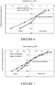
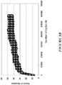
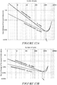
- Figures 9A, 9B , 10A and 10B show the results of the wheel tracker test carried out on two identical pairs of specimens in the fully constrained and the partially constrained setup. All the specimens in Figures 9A, 9B , 10A and 10B were made from AC20 mixes. The pair of specimens shown in Figures 9A and 9B used soft binder 80/100 penetration grade and air voids content 6.0%. The pair of specimens shown in Figures 10A and 10B used a harder binder grade 60/70 and lower air voids content of 4.3%. All specimens were tested at 50 °C. Figures 9A and 10A show the fully constrained test results for the 80/100 grade specimen and the 60/70 grade specimen respectively.
- Figures 9A and 10A show that the permanent deformation in the fully constrained test plateaus at 2.0 mm regardless of the binder type or air voids content.
- the fully constrained tests reached 50,000 cycles without the specimens experiencing tertiary failure.
- Figures 9B and 10B show the partially constrained test results for the 80/100 grade specimen and the 60/70 grade specimen respectively.
- Figures 9B and 10B show a significant difference between the two mix types in the partially constrained test. Both specimens experienced tertiary failure in less than 50,000 cycles.
- the AC20 mix made with the harder 60/70 binder and with 4.3% air voids content lasted nearly 20 times the number of cycles compared to the same AC20 mix with softer 80/100 binder and with higher voids content of 6.0%. This clearly demonstrates that the partially constrained test is more capable of detecting the effect of important mix parameters such as air voids content and binder type on permanent deformation.
- the excessive constraining stresses exerted on the asphalt mix by the specimen holder in the conventional wheel tracker test is one of the most important obstacles preventing the true material behaviour.
- the fully constrained test will most likely be able to capture the small part of the permanent deformation related to the mix densification. However, it is not likely be able to capture the shear related permanent deformations.
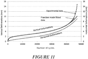
- Figure 11 shows the experimental data for the AC20, 60/70 binder, 7.0% air voids, 50 °C specimen displayed as a broken line curve and the Francken model fitted curve represented by solid lines superimposed on the same graph for both vertical and horizontal permanent deformations.
- the Francken model provided an excellent fit for the experimental data for the three phases of deformation: primary, secondary and tertiary.
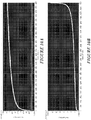
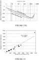
- the rate of change of permanent deformation given by Equation 2 was plotted against the number of cycles as shown in Figures 12A to 12G .
- d ⁇ dN ABN B ⁇ 1 + CDe DN
- Figures 12A to 12G show the results of the rate of permanent deformation versus the cycle number for six of the twenty tests conducted utilising the rut testing apparatus 200.
- Figures 12A to 12G and the data in Table 6 illustrate that by using the partially constrained specimen holder, almost every specimen reaches its failure point, with only very few exceptions. That was not the case for the conventional fully constrained test method. Moreover, unlike the fully constrained approach, the partially constrained wheel tracker test is more sensitive to mix parameters such as air voids content, aggregate gradation, binder type and also to the test temperature. Therefore, ranking the mixtures based on their permanent deformation behaviour becomes more reliable.
- Figures 12A and 12B show the rate of permanent deformation versus the number of cycles for AC20 and AC14, respectively. Both mixes have 60/70 grade bitumen and an air voids content of 7.0%. Both mixes were tested at 50 °C. Both horizontal and vertical permanent deformation show the coarse AC20 mix outperforming the medium AC14 mix. In addition, the rate of change of permanent deformation of both horizontal and vertical deformations provides useful information on how the permanent deformation developed in the loaded specimen. The vertical (downward) permanent deformation starts at a higher rate of deformation than the horizontal (lateral) permanent deformation until certain point after which the rate of horizontal permanent deformation overtakes the vertical deformation.
- the inventor designates this point as the critical flow number (N c ) which is defined as the number of cycles at which both vertical and horizontal permanent deformation progress at the same rate.
- the critical flow number, N c can be determined as the point of intersection between the rate of vertical permanent deformation curve and the rate of the horizontal permanent deformation curve as shown in Figures 12A to 12G .
- the mix Before the critical flow number, the mix will densify with rapid change of the air voids content, thus moving faster downward rather than moving laterally. Therefore, the vertical deformation will progress at a faster rate than the horizontal deformation. Beyond the critical flow number, the mix will move laterally at a faster rate with more shear deformation developing in the mix until failure.
- N h and N v are well correlated with a coefficient of determination R 2 of 0.96. It was also observed that N c is always larger than N h and smaller than N v as shown in Figures 12A to 12G (i.e. N h ⁇ N c ⁇ N v ).
- the critical number, N c can provide useful information regarding the mix lateral stability and therefore its rutting resistance.
- the partially constrained rut testing apparatus 200 provided a wealth of information to characterize the permanent deformation behaviour of asphalt.
- the measured parameters from the vertical (downward) and horizontal (lateral) permanent deformation showed sensitivity to the mix parameters and test temperatures.
- the change of aggregate gradation from coarse to fine aggregate, i.e. AC20 to AC14 causes the mix to undergo a higher deformation rate.
- binder grade hard binder 60/70 to soft binder 80/100
- air voids 3.5% to 7.0%)
- temperature 50 °C to 60 °C).
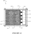
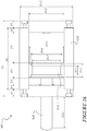
- Figure 14 shows a specimen holder 303 of an alternative embodiment rut testing apparatus for testing the susceptibility of a pavement specimen to rutting.
- the features and functionality and method of use will be the same as described for the apparatus 200 outlined in relation to figures 2 and 3 above, and like reference numerals indicate like parts with 100 added to each reference numeral.
- the specimen holder 303 comprises a first moveable support member 340 to support a first lateral side 310 of the specimen 301.
- the first moveable support member 340 comprises a plate that extends in the first direction FD.
- the first movable support member 340 is arranged to allow deformation of the specimen 301 in the lateral direction LD.
- the specimen holder 303 is arranged to allow the specimen 301 to deform in the lateral direction LD for substantially the entire test. In an embodiment, the specimen holder 303 is arranged to allow the specimen 301 to deform in the lateral direction LD for the entire test.
- a lateral displacement sensor 330 is arranged to determine deformation of the lateral side 310 of the specimen 301 in the lateral direction LD by measuring the movement of support member 340.
- the sensor comprises a dial test indicator (DTI) or any other suitable linear displacement sensor.
- the specimen holder 303 comprises a fixed support member 360 to support a second opposite lateral side 311 of the specimen.
- the fixed support member 360 is fixed to the base plate and/or end support members in any suitable way.
- End support members 320, 321 are fixed.
- the position of the moveable support member 340 is controlled to provide substantially constant pressure to the lateral sides 310, 311 of the specimen during testing.
- the moveable support member 340 is moved and controlled by hydraulic rams 341 mounted to a hydraulic block 342.
- An exemplary hydraulic ram is shown in figure 16 . Pressure is applied by the hydraulic rams 341 to the support member 340.
- the support member 340 applies pressure on the first side 310 equal to the reaction pressure on the second side 311.
- a bleed valve or other suitable mechanism is used to maintain substantially constant pressure during testing.
- the actual value of the applied lateral pressure can be computed from multilayer computer simulations similar to the analysis in Figures 6 and 7 and Table 2. By controlling the lateral pressure, the wheel tracker will provide a better representation of the actual field conditions and therefore better prediction and modelling of the rutting mechanism of the specimen and the material mix.
- the pressure applied by moveable support member 340 is greater than 0 kPa and up to 150 kPa. In some embodiments, the pressure is in the range of 10 kPa to 150 kPa. In some embodiments, the pressure is in the range of 10 kPa to 30 kPa. In some embodiments, the pressure is in the range of 20 kPa to 30 kPa. In some embodiments, more powerful hydraulic rams are used in order to achieve higher lateral pressure, for example up to 100 kPa to 150 kPa, to suit a wide variety of test conditions.
- the moveable support member 340 could be configured to apply 0 kPa pressure, to simulate an unconstrained side.
- a suitable pressure to be applied to a given specimen by the moveable support member 340 may be determined to suit the actual field condition. This pressure will depend on the thickness of the asphalt layer and shoulder support and whether the outer lane or inner lanes are considered. The suitable pressure will be less than the measured constraining stress in a fully constrained specimen.
- the applied pressure will also be varied depending on whether test data is required for inner wheel tracks or outer wheel tracks.
- the outer wheel track is of greater interest as this is generally where the worst damage occurs on an actual road.
- the outer wheel track generally has lower constraining stresses than the inner wheel track. Therefore, a lower pressure would be applied by the moveable support member 340 to simulate this scenario.
- the method of testing the susceptibility of a pavement specimen 301 to rutting is substantially the same as described for apparatus 200 above.
- the method comprises supporting a first lateral side 310 of the specimen with the first moveable support member 340.
- the first movable support member 340 is arranged to allow deformation of the specimen 301 in the lateral direction LD.
- the lateral deformation of the lateral side 310 of the specimen 301 is measured with a dial test indicator (DTI) or any other suitable linear displacement sensor arranged to measure the movement of support member 340 in the lateral direction LD.
- DTI dial test indicator
- the method comprises supporting a second opposite lateral side 311 of the specimen with the fixed support member 360.
- the method comprises supporting the ends of the specimen with the fixed end support members 320, 321.
- the method comprises controlling the position of the moveable support member 340 to provide substantially constant pressure to the sides 310, 311 of the specimen during testing.
- the moveable support member 340 is moved and controlled by hydraulic rams 341 mounted to a hydraulic block 342.
- An exemplary hydraulic ram is shown in figure 16 . Pressure is applied by the hydraulic rams 341 to the support member 340.
- the support member 340 applies pressure on the first side 310 equal to the reaction pressure on the second side 311.
- the pressure applied by moveable support member 340 is greater than 0 kPa and up to 150 kPa. In some embodiments, the pressure is in the range of 10 kPa to 150 kPa. In some embodiments, the pressure is in the range of 10 kPa to 30 kPa. In some embodiments, the pressure is in the range of 20 kPa to 30 kPa. In some embodiments, more powerful hydraulic rams are used in order to achieve higher lateral pressure, for example up to 100 kPa to 150 kPa, to suit a wide variety of test conditions. The pressure may be determined as outlined above.
- a bleed valve or other suitable mechanism is used to maintain substantially constant pressure during testing.
- the apparatus 301 will again suitably be provided with sensors to determine deformation of the specimen in the lateral direction LD and downward deformation of the specimen in the vertical direction. However, this apparatus 301 only uses a single lateral deformation sensor that is operatively coupled to the moveable support member 340.
- the specimen second support member 360 may also be a moveable support member, the second moveable support member 360 being arranged to allow deformation of the specimen 301 in the lateral direction LD.
- This embodiment will suitably comprise a second sensor associated with the second lateral side to determine deformation of the specimen 301 in the lateral direction LD.
- the specimen holder 303 is arranged to allow the specimen 301 to deform in the lateral direction LD for substantially the entire test. In an embodiment, the specimen holder 303 is arranged to allow the specimen 301 to deform in the lateral direction LD for the entire test.
- Lateral displacement sensors are arranged to determine deformation of the lateral sides 310 and 311 of the specimen 301 in the lateral direction LD by measuring the movement of support members 340, 360.
- the sensors comprise dial test indicators (DTIs) or any other suitable linear displacement sensors.
- the end support members 320, 321 are fixed.
- the position of the moveable support members 340, 360 is controlled to provide substantially constant pressure to the lateral sides 310, 311 of the specimen 301 during testing.
- the moveable support members 340, 360 are moved and controlled by hydraulic rams mounted to hydraulic blocks.
- An exemplary hydraulic ram is shown in figure 16 . Pressure is applied by the hydraulic rams to the support members 340, 360.
- the pressure applied by moveable support members 340, 360 is greater than 0 kPa and up to to 150 kPa. In some embodiments, the pressure is in the range of 10 kPa to 150 kPa. In some embodiments, the pressure is in the range of 10 kPa to 30 kPa. In some embodiments, the pressure is in the range of 20 kPa to 30 kPa. In some embodiments, more powerful hydraulic rams are used in order to achieve higher lateral pressure, for example up to 100 kPa to 150 kPa, to suit a wide variety of test conditions.
- the moveable support members 340, 360 could be configured to apply 0 kPa pressure, to simulate an unconstrained side.
- a suitable pressure to be applied to a given specimen by the moveable support members 340, 360 may be determined to suit the actual field condition. This pressure will depend on the thickness of the asphalt layer and shoulder support and whether the outer lane or inner lanes are considered. The suitable pressure will be less than the measured constraining stress in a fully constrained specimen.
- a bleed valve or other suitable mechanism is used to maintain substantially constant pressure during testing.
- the method of testing the susceptibility of a pavement specimen 301 to rutting is substantially the same as described for apparatus 300 above.
- the method comprises supporting a second opposite lateral side 311 of the specimen with the second moveable support member 360, wherein the second moveable support member is arranged to allow deformation of the specimen 301 in the lateral direction LD.
- the lateral deformation of the lateral sides 310, 311 of the specimen 301 is measured with dial test indicators (DTIs) or any other suitable linear displacement sensors arranged to measure the movement of support members 340, 360 in the lateral direction LD.
- DTIs dial test indicators
- any other suitable linear displacement sensors arranged to measure the movement of support members 340, 360 in the lateral direction LD.
- the method comprises controlling the position of the moveable support members to provide substantially constant pressure to the sides 310, 311 of the specimen 301 during testing.
- the moveable support members 340, 360 are moved and controlled by hydraulic rams mounted to hydraulic blocks.
- An exemplary hydraulic ram is shown in figure 16 . Pressure is applied by the hydraulic rams to the support members 340, 360.
- the pressure applied by moveable support members 340, 360 is greater than 0 kPa and up to 150 kPa. In some embodiments, the pressure is in the range of 10 kPa to 150 kPa. In some embodiments, the pressure is in the range of 10 kPa to 30 kPa. In some embodiments, the pressure is in the range of 20 kPa to 30 kPa.
- more powerful hydraulic rams are used in order to achieve higher lateral pressure, for example up to 100 kPa to 150 kPa, to suit a wide variety of test conditions.
- the pressure may be determined as outlined above.
- a bleed valve or other suitable mechanism is used to maintain substantially constant pressure during testing.
- Figure 15 shows a specimen holder 403 of an alternative embodiment rut testing apparatus for testing the susceptibility of a pavement specimen to rutting.
- the features and functionality and method of use will be the same as described for the apparatus 200 outlined in relation to figures 2 and 3 above, and like reference numerals indicate like parts with 200 added to each reference numeral.
- the specimen holder 403 comprises a first moveable support member 440 to support a first lateral side 410 of the specimen 401 and a first end moveable support member 450 to support a first end 420 of the specimen.
- the first movable support member 440 is arranged to allow deformation of the specimen 401 in the lateral direction LD and the first end moveable support member 450 is arranged to allow deformation of the specimen 401 in the first direction FD that extends between the opposite ends 420, 421 of the specimen.
- the specimen holder 403 is arranged to allow the specimen 401 to deform in the lateral direction LD and the first direction FD for substantially the entire test. In an embodiment, the specimen holder 403 is arranged to allow the specimen 401 to deform in the lateral direction LD and the first direction FD for the entire test.
- the specimen holder 403 comprises fixed support members 460, 470 to support a second opposite lateral side 411 of the specimen 401 and a second opposite end 421 of the specimen 401.
- the position of the moveable support members 440, 450 is controlled to provide substantially constant pressure in the range of 300 to 350 kPa to the sides 410, 411 and ends 420, 421 of the specimen 401 during testing.
- the moveable support members 440, 450 are moved and controlled by hydraulic rams 441, 451 mounted to hydraulic blocks 442, 452.
- An exemplary hydraulic ram is shown in figure 16 . Pressure is applied by the hydraulic rams 441, 451 to the support members 440, 450.
- the support member 440 applies pressure on the first side 410 equal to the reaction pressure on the second side 411.
- the support member 450 applies pressure on the first end 420 equal to the reaction pressure on the second end 421.
- the pressure applied by moveable support members 440, 450 is greater than 0 kPa and up to 150 kPa. In some embodiments, the pressure is in the range of 10 kPa to 150 kPa. In some embodiments, the pressure is in the range of 10 kPa to 30 kPa. In some embodiments, the pressure is in the range of 20 kPa to 30 kPa. In some embodiments, more powerful hydraulic rams are used in order to achieve higher pressure, for example up to 100 kPa to 150 kPa, to suit a wide variety of test conditions.
- greater pressure is applied by the end support member 450 than by the side support member 440.
- the side support member 440 could be configured to apply 0 kPa pressure to simulate an unconstrained side.
- a suitable pressure to be applied to a given specimen by the first moveable support member 440 may be determined to suit the actual field condition. This pressure will depend on the thickness of the asphalt layer and shoulder support and whether the outer lane or inner lanes are considered. The suitable pressure will be less than the measured constraining stress in a fully constrained specimen.
- an end displacement sensor 433 is arranged to determine deformation of the end 420 of the specimen 401 in the first direction FD that extends between the opposite ends by measuring the movement of support member 450.
- the sensor comprises a dial test indicator (DTI) or any other suitable linear displacement sensor.
- DTI dial test indicator
- Two flow numbers, N h1 and N h2 can be determined, one for horizontal displacement in each direction FD, LD. Both of these flow numbers N h1 and N h2 could be used, or the average of the flow numbers N h1 and N h2 could be used, in the method and apparatus of embodiments of the invention.
- the hydraulic rams 441 on the first lateral side support member 440 and the hydraulic rams 451 on the first end support member 450 may be configured or controlled to apply different pressures.
- the pressure applied to the lateral sides 410, 411 is the same as the pressure applied to the ends 420, 421. In other embodiments the pressure applied to the lateral sides 410, 411 is different to the pressure applied to the ends 420, 421.
- a bleed valve or other suitable mechanism is used to maintain substantially constant pressure during testing.
- embodiments comprising moveable support members on at least one lateral side and at least one end will be a better match for field conditions than embodiments with moveable support member(s) only in the lateral direction. As the embodiments with a moveable support member on at least one end will more accurately simulate the stresses in an actual pavement, they will provide a better prediction of permanent deformation. This test data can be used in modelling to predict material behaviour.
- the method of testing the susceptibility of a pavement specimen 401 to rutting is substantially the same as described for apparatus 200 above.
- the method comprises supporting the first lateral side 410 of the specimen 401 with the first moveable support member 440 and supporting a first end 420 of the specimen 401 with the first end moveable support member 450.
- the first movable support member 440 is arranged to allow deformation of the specimen 401 in the lateral direction LD and the first end moveable support member 450 is arranged to allow deformation of the specimen 401 in the first direction FD that extends between the opposite ends 420, 421 of the specimen.
- the method comprises supporting a second opposite lateral side 411 of the specimen 401 and a second opposite end 421 of the specimen with the fixed support members 460, 470.
- the method comprises controlling the position of the moveable support members 440, 450 to provide substantially constant pressure to the sides 410, 411 and ends 420, 421 of the specimen 401 during testing.
- the moveable support members 440, 450 are moved and controlled by hydraulic rams 441, 451 mounted to hydraulic blocks 442, 452.
- An exemplary hydraulic ram is shown in figure 16 . Pressure is applied by the hydraulic rams 441, 451 to the support members 440, 450.
- the support member 440 applies pressure on the first side 410 equal to the reaction pressure on the second side 411.
- the support member 450 applies pressure on the first end 420 equal to the reaction pressure on the second end 421.
- the pressure applied by moveable support members 440, 450 is greater than 0 kPa and up to 150 kPa. In some embodiments, the pressure is in the range of 10 kPa to 150 kPa. In some embodiments, the pressure is in the range of 10 kPa to 30 kPa. In some embodiments, the pressure is in the range of 20 kPa to 30 kPa. In some embodiments, more powerful hydraulic rams are used in order to achieve higher pressure, for example up to 100 kPa to 150 kPa, to suit a wide variety of test conditions. The pressure may be determined as outlined above.
- the deformation of the end 420 of the specimen 401 is measured with a dial test indicator (DTI) or any other suitable linear displacement sensor arranged to measure the movement of support member 450 in the first direction FD that extends between the opposite ends.
- DTI dial test indicator
- Two flow numbers, N h1 and N h2 can be determined, one for horizontal displacement in each direction FD, LD. Both of these flow numbers N h1 and N h2 could be used, or the average of the flow numbers N h1 and N h2 could be used, in the method and apparatus of embodiments of the invention. The average of N h1 and N h2 could be used to determine the resistance to lateral deformation.
- the hydraulic rams 441 on the first lateral side support member 440 and the hydraulic rams 451 on the first end support member 450 may be configured or controlled to apply different pressures.
- the pressure applied to the lateral sides 410, 411 is the same as the pressure applied to the ends 420, 421. In other embodiments the pressure applied to the lateral sides 410, 411 is different to the pressure applied to the ends 420, 421.
- a bleed valve or other suitable mechanism is used to maintain substantially constant pressure during testing.
- embodiments comprising moveable support members on at least one lateral side and at least one end will be a better match for field conditions than embodiments with moveable support member(s) only in the lateral direction. It is also understood that applying different pressures on the sides 410, 411 and ends 420, 421 better represents field conditions for some asphalt mixes.
- the second support member 460 to support a second lateral side 411 of the specimen 401 is a moveable support member and the second end support member 470 to support a second end 421 of the specimen 401 is a moveable support member.
- the moveable support members 460 and 470 will be supported and controlled in the same way described above for the support members 410, 420.
- the second movable support member 460 is arranged to allow deformation of the specimen 401 in the lateral direction LD and the second end moveable support member 470 is arranged to allow deformation of the specimen 401 in the first direction FD that extends between the opposite ends of the specimen 420, 421.
- the specimen holder 403 is arranged to allow the specimen 401 to deform in the lateral direction LD and the first direction FD for substantially the entire test. In an embodiment, the specimen holder 403 is arranged to allow the specimen 401 to deform in the lateral direction LD and the first direction FD for the entire test.
- This embodiment comprises a second sensor associated with the second lateral side 411 to determine deformation of the specimen 401 in the lateral direction LD.
- An alternative embodiment further comprises end displacement sensors associated with ends 420, 421 to determine deformation of the specimen 401 in the first direction FD that extends between the opposite ends.
- Two flow numbers, N h1 and N h2 can be determined, one for horizontal displacement in each direction FD, LD.
- N h1 can be determined based on the average deformation in the LD direction
- N h2 can be determined based on the average deformation in the FD direction. Both of these flow numbers N h1 and N h2 could be used, or the average of the flow numbers N h1 and N h2 could be used, in the method and apparatus of embodiments of the invention.
- a suitable pressure to be applied to a given specimen by the second moveable support member 460 and the second end moveable support member 470 may be determined to suit the actual field condition. This pressure will depend on the thickness of the asphalt layer and shoulder support and whether the outer lane or inner lanes are considered. The suitable pressure will be less than the measured constraining stress in a fully constrained specimen. The pressure may be in the ranges outlined above.
- the method of testing the susceptibility of a pavement specimen (401) to rutting is substantially the same as described for apparatus 400 above.
- the method comprises supporting a second lateral side 411 of the specimen 401 with the second moveable support member 460 and supporting a second opposite end 421 of the specimen with the second end moveable support member 450.
- the second movable support member is arranged to allow deformation of the specimen 401 in the lateral direction LD and the second end moveable support member is arranged to allow deformation of the specimen 401 in the first direction FD that extends between the opposite ends 420, 421 of the specimen.
- the method comprises controlling the position of the moveable support members 410, 420, 460, 470 to provide substantially constant pressure to the sides 410, 411 and ends 420, 421 of the specimen 401 during testing.
- the pressure may be determined as outlined above.
- moveable and fixed supports are possible, such as moveable support on two lateral sides and one end, and a fixed support on the other end.
- An alternative configuration is moveable support on one lateral side and two ends, and a fixed support on the other lateral side.
- the ram 800 comprises a piston 810 attached to a shaft 820.
- the piston is moveable within a housing 830.
- the ram also has a bleed valve to control the pressure that is applied by the ram, and thereby the pressure that is applied by the respective moveable support member to the specimen during testing.
- the bleed valve will be controllable to set the desired pressure.
- Exemplary dimensions are:
- the specimen, and specimen holder may be any suitable shape, such as square, rectangular, circular, or any other suitable shape.
- Reference herein may be used to directional terminology such as 'vertical', 'downward' etc. Those terms are intended in a relative sense compared to other directions, and are representative of use of the apparatus with the specimen holder in a horizontal orientation and with the wheel applying force to the specimen vertically. It will be appreciated that the apparatus could instead be oriented in a different way, such as with the specimen holder vertically and the wheel applying force horizontally.
Landscapes
- Health & Medical Sciences (AREA)
- Life Sciences & Earth Sciences (AREA)
- Chemical & Material Sciences (AREA)
- General Health & Medical Sciences (AREA)
- Physics & Mathematics (AREA)
- Analytical Chemistry (AREA)
- Biochemistry (AREA)
- General Physics & Mathematics (AREA)
- Immunology (AREA)
- Pathology (AREA)
- Food Science & Technology (AREA)
- Medicinal Chemistry (AREA)
- Engineering & Computer Science (AREA)
- Investigating Strength Of Materials By Application Of Mechanical Stress (AREA)
Claims (15)
- Ein Spurrillenprüfgerät zum Prüfen der Spurrillenanfälligkeit einer Straßenbelagsprobe, wobei das Gerät umfasst:einen Probenhalter zum Stützen der zu prüfenden Probe, wobei der Probenhalter so angeordnet ist, dass er die Probe von unten stützt und zwei gegenüberliegende Enden der Probe stützt, wobei der Probenhalter so angeordnet ist, dass eine oder mehrere seitliche Seiten der Probe im Wesentlichen nicht gestützt oder durch ein bewegliches Stützelement gestützt sind, um es der Probe zu ermöglichen, sich für im Wesentlichen einen gesamten Test in einer seitlichen Richtung zu verformen, die quer zu einer Richtung verläuft, die sich zwischen den gegenüberliegenden Enden erstreckt;ein Rad, das so angeordnet ist, dass es sich entlang mindestens eines Teils der Probe in der Richtung bewegt, die sich zwischen den gegenüberliegenden Enden erstreckt; undeinen Sensor, um eine Verformung der Probe in der seitlichen Richtung zu bestimmen.
- Ein Spurrillenprüfgerät gemäß Anspruch 1, wobei der Probenhalter so angeordnet ist, dass zwei seitliche Seiten der Probe während der Prüfung im Wesentlichen nicht gestützt sind; und vorzugsweise wobei das Spurrillenprüfgerät einen zweiten Sensor umfasst, der der zweiten seitlichen Seite zugeordnet ist, um die Verformung der Probe in der seitlichen Richtung zu bestimmen.
- Ein Spurrillenprüfgerät gemäß Anspruch 1, wobei der Probenhalter ein erstes bewegliches Stützelement umfasst, um eine erste seitliche Seite der Probe zu stützen, wobei das erste bewegliche Stützelement so angeordnet ist, dass es eine Verformung der Probe In der seitlichen Richtung ermöglicht.
- Ein Spurrillenprüfgerät gemäß Anspruch 3, wobei der Probenhalter ein festes Stützelement umfasst, um eine zweite, gegenüberliegende seitliche Seite der Probe zu stützen.
- Ein Spurrillenprüfgerät gemäß Anspruch 3, wobei der Probenhalter ein zweites bewegliches Stützelement umfasst, um eine zweite, gegenüberliegende seitliche Seite der Probe zu stützen, wobei das zweite bewegliche Stützelement so angeordnet ist, dass es eine Verformung der Probe in der seitlichen Richtung ermöglicht; und vorzugsweise wobei das Spurrillenprüfgerät einen zweiten Sensor umfasst, der der zweiten seitlichen Seite zugeordnet ist, um die Verformung der Probe in der seitlichen Richtung zu bestimmen.
- Ein Spurrillenprüfgerät gemäß einem der vorhergehenden Ansprüche, wobei der Probenhalter ein erstes bewegliches End-Stützelement umfasst, um ein erstes Ende der Probe zu stützen, wobei das erste bewegliche End-Stützelement so angeordnet ist, dass es eine Verformung der Probe in der Richtung ermöglicht, die sich zwischen den gegenüberliegenden Enden erstreckt.
- Ein Spurrillenprüfgerät gemäß Anspruch 6, wobei der Probenhalter festes End-Stützelement umfasst, um ein zweites, gegenüberliegendes Ende der Probe zu stützen.
- Ein Spurrillenprüfgerät gemäß Anspruch 6, wobei der Probenhalter ein zweites bewegliches End-Stützelement umfasst, um ein zweites, gegenüberliegendes Ende der Probe zu stützen, wobei das zweite bewegliche End-Stützelement so angeordnet ist, dass es eine Verformung der Probe in der Richtung ermöglicht, die sich zwischen den gegenüberliegenden Enden erstreckt.
- Ein Spurrillenprüfgerät gemäß einem der Ansprüche 3 bis 8, wobei die Position des/derbeweglichen Stützelements/Stützelemente so gesteuert ist, dass während der Prüfung ein im Wesentlichen konstanter Druck auf die Seiten und/oder Enden der Probe bereitgestellt wird.
- Ein Spurrillenprüfgerät gemäß einem der vorhergehenden Ansprüche, umfassend einen Sensor, um eine Verformung der Probe In einer Richtung zu bestimmen, die im Allgemeinen orthogonal zu der Richtung, die sich zwischen den gegenüberliegenden Enden erstreckt, und zur seitlichen Richtung ist.
- Ein Spurrillenprüfgerät gemäß einem der vorhergehenden Ansprüche, umfassend einen Prozessor, der dazu eingerichtet ist, eine grafische Darstellung der Verformung in der seitlichen Richtung und/oder in einer Richtung bereitzustellen, die im Allgemeinen orthogonal zu der Richtung, die sich zwischen den gegenüberliegenden Enden erstreckt, und zu der seitlichen Richtung ist; vorzugsweise wobei die grafische Darstellung die Änderungsrate der dauerhaften Verformung in der seitlichen Richtung und/oder in der Richtung zeigt, die im Allgemeinen orthogonal zu der Richtung, die sich zwischen den gegenüberliegenden Enden erstreckt, und der seitlichen Richtung ist; und vorzugsweise die grafische Darstellung die Anzahl der Zyklen zeigt, bei denen die dauerhafte Verformung in beiden Richtungen mit der gleichen Rate fortschreitet.
- Ein Spurrillenprüfgerät gemäß einem der vorhergehenden Ansprüche, umfassend einen Prozessor, der dazu eingerichtet ist, das Ausmaß der Verformung in der seitlichen Richtung und/oder in einer Richtung zu bestimmen, die im Allgemeinen orthogonal zu der Richtung, die sich zwischen den gegenüberliegenden Enden erstreckt, und der seitlichen Richtung Ist; vorzugsweise wobei der Prozessor dazu eingerichtet ist, die Änderungsrate der dauerhaften Verformung in der seitlichen Richtung und/oder in der Richtung zu bestimmen, die im Allgemeinen orthogonal zu der Richtung, die sich zwischen den gegenüberliegenden Enden erstreckt, und zu der seitlichen Richtung ist; und vorzugsweise wobei der Prozessor dazu eingerichtet ist, die Anzahl von Zyklen zu bestimmen, bei denen die dauerhafte Verformung in beiden Richtungen mit der gleichen Rate fortschreitet.
- Ein Spurrillenprüfgerät gemäß Anspruch 12, wobei der Prozessor dazu eingerichtet ist, basierend auf der bestimmten dauerhaften Verformung in der seitlichen Richtung die dauerhafte Verformung in der Richtung zu bestimmen oder abzuschätzen, die im Allgemeinen orthogonal zu der Richtung, die sich zwischen den gegenüberliegenden Enden erstreckt, und zu der seitlichen Richtung ist.
- Ein Spurrillenprüfgerät gemäß einem der vorhergehenden Ansprüche, wobei die seitliche Richtung im Wesentlichen orthogonal zu der Richtung ist, die sich zwischen den gegenüberliegenden Enden erstreckt.
- Verfahren zum Prüfen der Spurrinnenanfälligkeit einer Straßenbelagsprobe, wobei das Verfahren umfasst:Stützen einer Straßenbelagsprobe in einem Probenhalter, wobei der Probenhalter so angeordnet ist, dass er die Probe von unten stützt und zwei gegenüberliegende Enden der Probe stützt, wobei der Probenhalter so angeordnet ist, dass eine oder mehrere seitliche Seiten der Probe im Wesentlichen nicht gestützt oder durch ein bewegliches Stützelement gestützt werden, um es der Probe zu ermöglichen, sich für im Wesentlichen einen gesamten Test in einer seitlichen Richtung zu verformen, die quer zu einer Richtung verläuft, die sich zwischen den gegenüberliegenden Enden erstreckt;Bewegen eines Rades entlang mindestens eines Teils der Probe in der Richtung, die sich zwischen den gegenüberliegenden Enden erstreckt; undMessen einer Verformung der Probe in der seitlichen Richtung.
Applications Claiming Priority (2)
| Application Number | Priority Date | Filing Date | Title |
|---|---|---|---|
| NZ72176516 | 2016-06-30 | ||
| PCT/NZ2017/050088 WO2018004360A1 (en) | 2016-06-30 | 2017-06-28 | Apparatus and method for testing a pavement specimen |
Publications (3)
| Publication Number | Publication Date |
|---|---|
| EP3479095A1 EP3479095A1 (de) | 2019-05-08 |
| EP3479095A4 EP3479095A4 (de) | 2020-03-04 |
| EP3479095B1 true EP3479095B1 (de) | 2021-02-24 |
Family
ID=60785240
Family Applications (1)
| Application Number | Title | Priority Date | Filing Date |
|---|---|---|---|
| EP17820611.6A Not-in-force EP3479095B1 (de) | 2016-06-30 | 2017-06-28 | Vorrichtung und verfahren zur prüfung eines asphaltprüflings |
Country Status (5)
| Country | Link |
|---|---|
| US (1) | US10883906B2 (de) |
| EP (1) | EP3479095B1 (de) |
| CN (1) | CN109690284B (de) |
| AU (1) | AU2017287792B2 (de) |
| WO (1) | WO2018004360A1 (de) |
Families Citing this family (10)
| Publication number | Priority date | Publication date | Assignee | Title |
|---|---|---|---|---|
| WO2018129483A1 (en) * | 2017-01-08 | 2018-07-12 | Troxler Electronic Laboratories, Inc. | Apparatus, method, and associated system for testing a pavement material sample |
| US10753838B2 (en) * | 2017-07-18 | 2020-08-25 | Instrotek, Inc. | Systems and methods for verification and calibration of hamburg wheel tracker devices |
| CN110031350A (zh) * | 2019-03-20 | 2019-07-19 | 天津久荣工业技术有限公司 | 停车库地坪耐磨性能试验机 |
| CN110186789B (zh) * | 2019-06-20 | 2022-07-22 | 长沙理工大学 | 基于灰色系统的建筑废弃物路基永久变形正交预估方法 |
| CN110763541B (zh) * | 2019-11-22 | 2023-10-24 | 长安大学 | 一种具有抗剪性能测试功能的车辙板成型装置 |
| PL239988B1 (pl) * | 2020-02-19 | 2022-02-07 | Politechnika Wroclawska | S posób oznaczania odporności na ścieranie podkładów podłogowych |
| CN111781077B (zh) * | 2020-07-10 | 2023-03-07 | 哈尔滨工业大学 | 一种提高沥青混合料流变次数计算精度的方法 |
| CN114861433B (zh) * | 2022-04-25 | 2023-11-07 | 许昌华杰公路勘察设计有限责任公司 | 一种能够模拟纵坡条件下沥青路面车辙的仿真装置 |
| CN115078251A (zh) * | 2022-06-14 | 2022-09-20 | 长安大学 | 一种坑槽修补用新旧路面界面粘结性能测试方法及装置 |
| CN116296929B (zh) * | 2023-05-08 | 2023-08-08 | 昆明理工大学 | 一种铁尾矿砂沥青混凝土车辙试验装置 |
Family Cites Families (15)
| Publication number | Priority date | Publication date | Assignee | Title |
|---|---|---|---|---|
| US5969261A (en) | 1996-01-11 | 1999-10-19 | Troxler Electronics Laboratories, Inc. | Apparatus and method for measuring rutting susceptibility |
| US5659140A (en) * | 1996-08-13 | 1997-08-19 | Pavement Technology, Inc. | Testing machine for pavement samples |
| JP2895814B2 (ja) * | 1996-12-24 | 1999-05-24 | ニッケン株式会社 | ホイールトラッキング試験機 |
| US6125685A (en) | 1997-09-30 | 2000-10-03 | The Board Of Trustees Of The University Of Arkansas | Apparatus and method for the evaluation of asphalt mixes |
| CN201402236Y (zh) * | 2009-04-21 | 2010-02-10 | 华南理工大学 | 主驱动轮式路面材料测试装置 |
| US9234825B2 (en) | 2011-03-29 | 2016-01-12 | University Of Tennessee Research Foundation | Method and apparatus for fatigue and viscoelastic property testing of asphalt mixtures using a loaded wheel tester |
| KR101233058B1 (ko) | 2011-11-17 | 2013-02-13 | 주식회사 로드코리아 | 소형 포장가속시험 장치 |
| CN103245571B (zh) * | 2013-05-02 | 2015-01-28 | 大连理工大学 | 沥青混合料旋转剪切破坏性能测定试验装置 |
| CN103866675A (zh) * | 2014-03-21 | 2014-06-18 | 长安大学 | 一种车辙破坏层位的自动无损识别方法 |
| US9964471B2 (en) * | 2014-04-14 | 2018-05-08 | Instrotek, Inc. | Wheel-tracking devices and related systems and methods |
| CN204789129U (zh) | 2015-07-24 | 2015-11-18 | 温州市正诚工程质量检测有限公司 | 一种车辙试验仪的试验车机构 |
| CN204789201U (zh) | 2015-07-24 | 2015-11-18 | 温州市正诚工程质量检测有限公司 | 一种车辙试验仪的车辙模拟机构 |
| CN204789191U (zh) | 2015-07-24 | 2015-11-18 | 温州市正诚工程质量检测有限公司 | 一种车辙试验仪 |
| CN205175350U (zh) * | 2015-12-09 | 2016-04-20 | 山东省交通科学研究院 | 一种车辙横断面线型检测与分析仪 |
| US10718699B2 (en) * | 2016-01-28 | 2020-07-21 | William B. Coe | Rolling cyclic fatigue test platform for determining asphalt ductility |
-
2017
- 2017-06-28 WO PCT/NZ2017/050088 patent/WO2018004360A1/en not_active Ceased
- 2017-06-28 AU AU2017287792A patent/AU2017287792B2/en not_active Ceased
- 2017-06-28 CN CN201780052967.6A patent/CN109690284B/zh not_active Expired - Fee Related
- 2017-06-28 EP EP17820611.6A patent/EP3479095B1/de not_active Not-in-force
- 2017-06-28 US US16/309,988 patent/US10883906B2/en active Active
Non-Patent Citations (1)
| Title |
|---|
| None * |
Also Published As
| Publication number | Publication date |
|---|---|
| EP3479095A4 (de) | 2020-03-04 |
| WO2018004360A1 (en) | 2018-01-04 |
| AU2017287792A1 (en) | 2019-01-03 |
| CN109690284B (zh) | 2021-10-01 |
| EP3479095A1 (de) | 2019-05-08 |
| US20190323933A1 (en) | 2019-10-24 |
| CN109690284A (zh) | 2019-04-26 |
| AU2017287792B2 (en) | 2022-06-30 |
| US10883906B2 (en) | 2021-01-05 |
Similar Documents
| Publication | Publication Date | Title |
|---|---|---|
| EP3479095B1 (de) | Vorrichtung und verfahren zur prüfung eines asphaltprüflings | |
| Seibi et al. | Constitutive relations for asphalt concrete under high rates of loading | |
| Brown et al. | Performance testing for hot mix asphalt | |
| Chaturabong et al. | Mechanisms of asphalt mixture rutting in the dry Hamburg Wheel Tracking test and the potential to be alternative test in measuring rutting resistance | |
| Mo et al. | 2D and 3D meso-scale finite element models for ravelling analysis of porous asphalt concrete | |
| Ji et al. | Application of asphalt mixture shear strength to evaluate pavement rutting with accelerated loading facility (ALF) | |
| Ahmed et al. | Combined effect of asphalt concrete cross-anisotropy and temperature variation on pavement stress–strain under dynamic loading | |
| Al-Khateeb et al. | Rutting prediction of flexible pavements using finite element modeling | |
| Diakhate et al. | Shear fatigue behaviour of tack coats in pavements | |
| Zhalehjoo et al. | The effect of instrumentation on the determination of the resilient modulus of unbound granular materials using advanced repeated load triaxial testing | |
| Leiva-Villacorta et al. | Influence of tire footprint area and pressure distribution on pavement responses | |
| Hornych et al. | Selection and evaluation of models for prediction of permanent deformations of unbound granular materials in road pavements | |
| Novak et al. | Tire contact stresses and their effects on instability rutting of asphalt mixture pavements: three-dimensional finite element analysis | |
| Grasmick et al. | Comparison of multiple sensor deflection data from lightweight and falling weight deflectometer tests on layered soil | |
| Vinson | Fundamentals of resilient modulus testing | |
| Nabizadeh et al. | Validation of the subgrade shear strength parameters estimation methodology using light weight deflectometer: Numerical simulation and measured testing data | |
| Lacey et al. | THREE-DIMENSIONAL FINITE ELEMENT MODEL FOR FLEXIBLE PAVEMENT ANALYSES BASED ON FIELD MODULUS MEASUREMENTS. | |
| Tutumluer | State of the art: Anisotropic characterization of unbound aggregate layers in flexible pavements | |
| Long et al. | Improved design for driven piles based on a pile load test program in Illinois: phase 2. | |
| Bodin et al. | Comparison of small and large scale wheel tracking devices | |
| Tehrani et al. | The effect of water content on light weight deflectometer measurements | |
| NZ748963A (en) | Apparatus and method for testing a pavement specimen | |
| Xu et al. | Modeling asphalt pavement rutting under accelerated testing | |
| Buonsanti et al. | Impact dynamics on granular plate | |
| Zhao et al. | Experimental study and new prediction model on stress-dependent resilient modulus of fine-grained subgrade soil |
Legal Events
| Date | Code | Title | Description |
|---|---|---|---|
| STAA | Information on the status of an ep patent application or granted ep patent |
Free format text: STATUS: THE INTERNATIONAL PUBLICATION HAS BEEN MADE |
|
| PUAI | Public reference made under article 153(3) epc to a published international application that has entered the european phase |
Free format text: ORIGINAL CODE: 0009012 |
|
| STAA | Information on the status of an ep patent application or granted ep patent |
Free format text: STATUS: REQUEST FOR EXAMINATION WAS MADE |
|
| 17P | Request for examination filed |
Effective date: 20190114 |
|
| AK | Designated contracting states |
Kind code of ref document: A1 Designated state(s): AL AT BE BG CH CY CZ DE DK EE ES FI FR GB GR HR HU IE IS IT LI LT LU LV MC MK MT NL NO PL PT RO RS SE SI SK SM TR |
|
| AX | Request for extension of the european patent |
Extension state: BA ME |
|
| DAV | Request for validation of the european patent (deleted) | ||
| DAX | Request for extension of the european patent (deleted) | ||
| A4 | Supplementary search report drawn up and despatched |
Effective date: 20200203 |
|
| RIC1 | Information provided on ipc code assigned before grant |
Ipc: G01N 19/00 20060101ALN20200128BHEP Ipc: G01N 3/56 20060101ALN20200128BHEP Ipc: G01N 33/42 20060101AFI20200128BHEP |
|
| REG | Reference to a national code |
Ref country code: DE Ref legal event code: R079 Ref document number: 602017033467 Country of ref document: DE Free format text: PREVIOUS MAIN CLASS: G01N0003340000 Ipc: G01N0033420000 |
|
| RIC1 | Information provided on ipc code assigned before grant |
Ipc: G01N 33/42 20060101AFI20200904BHEP Ipc: G01N 3/56 20060101ALN20200904BHEP Ipc: G01N 19/00 20060101ALN20200904BHEP |
|
| GRAP | Despatch of communication of intention to grant a patent |
Free format text: ORIGINAL CODE: EPIDOSNIGR1 |
|
| STAA | Information on the status of an ep patent application or granted ep patent |
Free format text: STATUS: GRANT OF PATENT IS INTENDED |
|
| INTG | Intention to grant announced |
Effective date: 20201021 |
|
| GRAS | Grant fee paid |
Free format text: ORIGINAL CODE: EPIDOSNIGR3 |
|
| GRAA | (expected) grant |
Free format text: ORIGINAL CODE: 0009210 |
|
| STAA | Information on the status of an ep patent application or granted ep patent |
Free format text: STATUS: THE PATENT HAS BEEN GRANTED |
|
| AK | Designated contracting states |
Kind code of ref document: B1 Designated state(s): AL AT BE BG CH CY CZ DE DK EE ES FI FR GB GR HR HU IE IS IT LI LT LU LV MC MK MT NL NO PL PT RO RS SE SI SK SM TR |
|
| REG | Reference to a national code |
Ref country code: CH Ref legal event code: EP |
|
| REG | Reference to a national code |
Ref country code: AT Ref legal event code: REF Ref document number: 1365127 Country of ref document: AT Kind code of ref document: T Effective date: 20210315 |
|
| REG | Reference to a national code |
Ref country code: IE Ref legal event code: FG4D |
|
| REG | Reference to a national code |
Ref country code: DE Ref legal event code: R096 Ref document number: 602017033467 Country of ref document: DE |
|
| REG | Reference to a national code |
Ref country code: NL Ref legal event code: FP |
|
| REG | Reference to a national code |
Ref country code: LT Ref legal event code: MG9D |
|
| PG25 | Lapsed in a contracting state [announced via postgrant information from national office to epo] |
Ref country code: LT Free format text: LAPSE BECAUSE OF FAILURE TO SUBMIT A TRANSLATION OF THE DESCRIPTION OR TO PAY THE FEE WITHIN THE PRESCRIBED TIME-LIMIT Effective date: 20210224 Ref country code: BG Free format text: LAPSE BECAUSE OF FAILURE TO SUBMIT A TRANSLATION OF THE DESCRIPTION OR TO PAY THE FEE WITHIN THE PRESCRIBED TIME-LIMIT Effective date: 20210524 Ref country code: FI Free format text: LAPSE BECAUSE OF FAILURE TO SUBMIT A TRANSLATION OF THE DESCRIPTION OR TO PAY THE FEE WITHIN THE PRESCRIBED TIME-LIMIT Effective date: 20210224 Ref country code: HR Free format text: LAPSE BECAUSE OF FAILURE TO SUBMIT A TRANSLATION OF THE DESCRIPTION OR TO PAY THE FEE WITHIN THE PRESCRIBED TIME-LIMIT Effective date: 20210224 Ref country code: GR Free format text: LAPSE BECAUSE OF FAILURE TO SUBMIT A TRANSLATION OF THE DESCRIPTION OR TO PAY THE FEE WITHIN THE PRESCRIBED TIME-LIMIT Effective date: 20210525 Ref country code: PT Free format text: LAPSE BECAUSE OF FAILURE TO SUBMIT A TRANSLATION OF THE DESCRIPTION OR TO PAY THE FEE WITHIN THE PRESCRIBED TIME-LIMIT Effective date: 20210624 Ref country code: NO Free format text: LAPSE BECAUSE OF FAILURE TO SUBMIT A TRANSLATION OF THE DESCRIPTION OR TO PAY THE FEE WITHIN THE PRESCRIBED TIME-LIMIT Effective date: 20210524 |
|
| PGFP | Annual fee paid to national office [announced via postgrant information from national office to epo] |
Ref country code: FR Payment date: 20210618 Year of fee payment: 5 Ref country code: NL Payment date: 20210621 Year of fee payment: 5 |
|
| REG | Reference to a national code |
Ref country code: AT Ref legal event code: MK05 Ref document number: 1365127 Country of ref document: AT Kind code of ref document: T Effective date: 20210224 |
|
| PG25 | Lapsed in a contracting state [announced via postgrant information from national office to epo] |
Ref country code: LV Free format text: LAPSE BECAUSE OF FAILURE TO SUBMIT A TRANSLATION OF THE DESCRIPTION OR TO PAY THE FEE WITHIN THE PRESCRIBED TIME-LIMIT Effective date: 20210224 Ref country code: RS Free format text: LAPSE BECAUSE OF FAILURE TO SUBMIT A TRANSLATION OF THE DESCRIPTION OR TO PAY THE FEE WITHIN THE PRESCRIBED TIME-LIMIT Effective date: 20210224 Ref country code: PL Free format text: LAPSE BECAUSE OF FAILURE TO SUBMIT A TRANSLATION OF THE DESCRIPTION OR TO PAY THE FEE WITHIN THE PRESCRIBED TIME-LIMIT Effective date: 20210224 Ref country code: SE Free format text: LAPSE BECAUSE OF FAILURE TO SUBMIT A TRANSLATION OF THE DESCRIPTION OR TO PAY THE FEE WITHIN THE PRESCRIBED TIME-LIMIT Effective date: 20210224 |
|
| PG25 | Lapsed in a contracting state [announced via postgrant information from national office to epo] |
Ref country code: IS Free format text: LAPSE BECAUSE OF FAILURE TO SUBMIT A TRANSLATION OF THE DESCRIPTION OR TO PAY THE FEE WITHIN THE PRESCRIBED TIME-LIMIT Effective date: 20210624 |
|
| PG25 | Lapsed in a contracting state [announced via postgrant information from national office to epo] |
Ref country code: CZ Free format text: LAPSE BECAUSE OF FAILURE TO SUBMIT A TRANSLATION OF THE DESCRIPTION OR TO PAY THE FEE WITHIN THE PRESCRIBED TIME-LIMIT Effective date: 20210224 Ref country code: EE Free format text: LAPSE BECAUSE OF FAILURE TO SUBMIT A TRANSLATION OF THE DESCRIPTION OR TO PAY THE FEE WITHIN THE PRESCRIBED TIME-LIMIT Effective date: 20210224 Ref country code: AT Free format text: LAPSE BECAUSE OF FAILURE TO SUBMIT A TRANSLATION OF THE DESCRIPTION OR TO PAY THE FEE WITHIN THE PRESCRIBED TIME-LIMIT Effective date: 20210224 Ref country code: SM Free format text: LAPSE BECAUSE OF FAILURE TO SUBMIT A TRANSLATION OF THE DESCRIPTION OR TO PAY THE FEE WITHIN THE PRESCRIBED TIME-LIMIT Effective date: 20210224 |
|
| REG | Reference to a national code |
Ref country code: DE Ref legal event code: R097 Ref document number: 602017033467 Country of ref document: DE |
|
| PG25 | Lapsed in a contracting state [announced via postgrant information from national office to epo] |
Ref country code: SK Free format text: LAPSE BECAUSE OF FAILURE TO SUBMIT A TRANSLATION OF THE DESCRIPTION OR TO PAY THE FEE WITHIN THE PRESCRIBED TIME-LIMIT Effective date: 20210224 Ref country code: DK Free format text: LAPSE BECAUSE OF FAILURE TO SUBMIT A TRANSLATION OF THE DESCRIPTION OR TO PAY THE FEE WITHIN THE PRESCRIBED TIME-LIMIT Effective date: 20210224 Ref country code: RO Free format text: LAPSE BECAUSE OF FAILURE TO SUBMIT A TRANSLATION OF THE DESCRIPTION OR TO PAY THE FEE WITHIN THE PRESCRIBED TIME-LIMIT Effective date: 20210224 |
|
| PLBE | No opposition filed within time limit |
Free format text: ORIGINAL CODE: 0009261 |
|
| STAA | Information on the status of an ep patent application or granted ep patent |
Free format text: STATUS: NO OPPOSITION FILED WITHIN TIME LIMIT |
|
| PG25 | Lapsed in a contracting state [announced via postgrant information from national office to epo] |
Ref country code: MC Free format text: LAPSE BECAUSE OF FAILURE TO SUBMIT A TRANSLATION OF THE DESCRIPTION OR TO PAY THE FEE WITHIN THE PRESCRIBED TIME-LIMIT Effective date: 20210224 Ref country code: AL Free format text: LAPSE BECAUSE OF FAILURE TO SUBMIT A TRANSLATION OF THE DESCRIPTION OR TO PAY THE FEE WITHIN THE PRESCRIBED TIME-LIMIT Effective date: 20210224 Ref country code: ES Free format text: LAPSE BECAUSE OF FAILURE TO SUBMIT A TRANSLATION OF THE DESCRIPTION OR TO PAY THE FEE WITHIN THE PRESCRIBED TIME-LIMIT Effective date: 20210224 |
|
| REG | Reference to a national code |
Ref country code: CH Ref legal event code: PL |
|
| 26N | No opposition filed |
Effective date: 20211125 |
|
| PG25 | Lapsed in a contracting state [announced via postgrant information from national office to epo] |
Ref country code: SI Free format text: LAPSE BECAUSE OF FAILURE TO SUBMIT A TRANSLATION OF THE DESCRIPTION OR TO PAY THE FEE WITHIN THE PRESCRIBED TIME-LIMIT Effective date: 20210224 |
|
| REG | Reference to a national code |
Ref country code: BE Ref legal event code: MM Effective date: 20210630 |
|
| PG25 | Lapsed in a contracting state [announced via postgrant information from national office to epo] |
Ref country code: LU Free format text: LAPSE BECAUSE OF NON-PAYMENT OF DUE FEES Effective date: 20210628 |
|
| PG25 | Lapsed in a contracting state [announced via postgrant information from national office to epo] |
Ref country code: LI Free format text: LAPSE BECAUSE OF NON-PAYMENT OF DUE FEES Effective date: 20210630 Ref country code: IT Free format text: LAPSE BECAUSE OF FAILURE TO SUBMIT A TRANSLATION OF THE DESCRIPTION OR TO PAY THE FEE WITHIN THE PRESCRIBED TIME-LIMIT Effective date: 20210224 Ref country code: IE Free format text: LAPSE BECAUSE OF NON-PAYMENT OF DUE FEES Effective date: 20210628 Ref country code: CH Free format text: LAPSE BECAUSE OF NON-PAYMENT OF DUE FEES Effective date: 20210630 |
|
| PG25 | Lapsed in a contracting state [announced via postgrant information from national office to epo] |
Ref country code: IS Free format text: LAPSE BECAUSE OF FAILURE TO SUBMIT A TRANSLATION OF THE DESCRIPTION OR TO PAY THE FEE WITHIN THE PRESCRIBED TIME-LIMIT Effective date: 20210624 |
|
| PG25 | Lapsed in a contracting state [announced via postgrant information from national office to epo] |
Ref country code: BE Free format text: LAPSE BECAUSE OF NON-PAYMENT OF DUE FEES Effective date: 20210630 |
|
| REG | Reference to a national code |
Ref country code: NL Ref legal event code: MM Effective date: 20220701 |
|
| PG25 | Lapsed in a contracting state [announced via postgrant information from national office to epo] |
Ref country code: NL Free format text: LAPSE BECAUSE OF NON-PAYMENT OF DUE FEES Effective date: 20220701 |
|
| PG25 | Lapsed in a contracting state [announced via postgrant information from national office to epo] |
Ref country code: FR Free format text: LAPSE BECAUSE OF NON-PAYMENT OF DUE FEES Effective date: 20220630 |
|
| PG25 | Lapsed in a contracting state [announced via postgrant information from national office to epo] |
Ref country code: CY Free format text: LAPSE BECAUSE OF FAILURE TO SUBMIT A TRANSLATION OF THE DESCRIPTION OR TO PAY THE FEE WITHIN THE PRESCRIBED TIME-LIMIT Effective date: 20210224 |
|
| PG25 | Lapsed in a contracting state [announced via postgrant information from national office to epo] |
Ref country code: HU Free format text: LAPSE BECAUSE OF FAILURE TO SUBMIT A TRANSLATION OF THE DESCRIPTION OR TO PAY THE FEE WITHIN THE PRESCRIBED TIME-LIMIT; INVALID AB INITIO Effective date: 20170628 |
|
| PG25 | Lapsed in a contracting state [announced via postgrant information from national office to epo] |
Ref country code: MK Free format text: LAPSE BECAUSE OF FAILURE TO SUBMIT A TRANSLATION OF THE DESCRIPTION OR TO PAY THE FEE WITHIN THE PRESCRIBED TIME-LIMIT Effective date: 20210224 |
|
| PG25 | Lapsed in a contracting state [announced via postgrant information from national office to epo] |
Ref country code: TR Free format text: LAPSE BECAUSE OF FAILURE TO SUBMIT A TRANSLATION OF THE DESCRIPTION OR TO PAY THE FEE WITHIN THE PRESCRIBED TIME-LIMIT Effective date: 20210224 |
|
| PG25 | Lapsed in a contracting state [announced via postgrant information from national office to epo] |
Ref country code: MT Free format text: LAPSE BECAUSE OF FAILURE TO SUBMIT A TRANSLATION OF THE DESCRIPTION OR TO PAY THE FEE WITHIN THE PRESCRIBED TIME-LIMIT Effective date: 20210224 |
|
| PGFP | Annual fee paid to national office [announced via postgrant information from national office to epo] |
Ref country code: DE Payment date: 20241205 Year of fee payment: 8 |
|
| PGFP | Annual fee paid to national office [announced via postgrant information from national office to epo] |
Ref country code: GB Payment date: 20241203 Year of fee payment: 8 |
|
| REG | Reference to a national code |
Ref country code: DE Ref legal event code: R119 Ref document number: 602017033467 Country of ref document: DE |
|
| GBPC | Gb: european patent ceased through non-payment of renewal fee |
Effective date: 20250628 |
|
| PG25 | Lapsed in a contracting state [announced via postgrant information from national office to epo] |
Ref country code: GB Free format text: LAPSE BECAUSE OF NON-PAYMENT OF DUE FEES Effective date: 20250628 |
|
| PG25 | Lapsed in a contracting state [announced via postgrant information from national office to epo] |
Ref country code: DE Free format text: LAPSE BECAUSE OF NON-PAYMENT OF DUE FEES Effective date: 20260101 |