EP3479143B1 - Tragbares strahlungsmessgerät und verfahren - Google Patents
Tragbares strahlungsmessgerät und verfahren Download PDFInfo
- Publication number
- EP3479143B1 EP3479143B1 EP17737026.9A EP17737026A EP3479143B1 EP 3479143 B1 EP3479143 B1 EP 3479143B1 EP 17737026 A EP17737026 A EP 17737026A EP 3479143 B1 EP3479143 B1 EP 3479143B1
- Authority
- EP
- European Patent Office
- Prior art keywords
- survey meter
- portable survey
- portable
- measurement
- instantaneous
- Prior art date
- Legal status (The legal status is an assumption and is not a legal conclusion. Google has not performed a legal analysis and makes no representation as to the accuracy of the status listed.)
- Active
Links
Images
Classifications
-
- G—PHYSICS
- G01—MEASURING; TESTING
- G01T—MEASUREMENT OF NUCLEAR OR X-RADIATION
- G01T1/00—Measuring X-radiation, gamma radiation, corpuscular radiation, or cosmic radiation
- G01T1/16—Measuring radiation intensity
- G01T1/169—Exploration, location of contaminated surface areas
-
- G—PHYSICS
- G01—MEASURING; TESTING
- G01S—RADIO DIRECTION-FINDING; RADIO NAVIGATION; DETERMINING DISTANCE OR VELOCITY BY USE OF RADIO WAVES; LOCATING OR PRESENCE-DETECTING BY USE OF THE REFLECTION OR RERADIATION OF RADIO WAVES; ANALOGOUS ARRANGEMENTS USING OTHER WAVES
- G01S13/00—Systems using the reflection or reradiation of radio waves, e.g. radar systems; Analogous systems using reflection or reradiation of waves whose nature or wavelength is irrelevant or unspecified
- G01S13/02—Systems using reflection of radio waves, e.g. primary radar systems; Analogous systems
- G01S13/06—Systems determining position data of a target
- G01S13/08—Systems for measuring distance only
-
- G—PHYSICS
- G01—MEASURING; TESTING
- G01S—RADIO DIRECTION-FINDING; RADIO NAVIGATION; DETERMINING DISTANCE OR VELOCITY BY USE OF RADIO WAVES; LOCATING OR PRESENCE-DETECTING BY USE OF THE REFLECTION OR RERADIATION OF RADIO WAVES; ANALOGOUS ARRANGEMENTS USING OTHER WAVES
- G01S15/00—Systems using the reflection or reradiation of acoustic waves, e.g. sonar systems
- G01S15/02—Systems using the reflection or reradiation of acoustic waves, e.g. sonar systems using reflection of acoustic waves
- G01S15/06—Systems determining the position data of a target
- G01S15/08—Systems for measuring distance only
-
- G—PHYSICS
- G01—MEASURING; TESTING
- G01S—RADIO DIRECTION-FINDING; RADIO NAVIGATION; DETERMINING DISTANCE OR VELOCITY BY USE OF RADIO WAVES; LOCATING OR PRESENCE-DETECTING BY USE OF THE REFLECTION OR RERADIATION OF RADIO WAVES; ANALOGOUS ARRANGEMENTS USING OTHER WAVES
- G01S17/00—Systems using the reflection or reradiation of electromagnetic waves other than radio waves, e.g. lidar systems
- G01S17/02—Systems using the reflection of electromagnetic waves other than radio waves
- G01S17/06—Systems determining position data of a target
- G01S17/08—Systems determining position data of a target for measuring distance only
Definitions
- the present invention relates to a portable survey meter and a method for measuring radiation. More particularly, an embodiment of this invention relates to an autonomous, portable survey meter for collecting spatially registered radiation measurements within a region such as a nuclear facility.
- US2012/0043471 A1 discloses a position and orientation determination system for a radiation detector.
- WO2015/024694 A1 discloses 3D topographic and radiological modeling of an environment.
- a radiological survey of a facility may be performed, with the positions and measurements recorded. At a later point in time, it may be desirable to repeat the survey to determine how the distribution of radiation has changed. Radiological measurements are sensitive to the position at which they are taken. It is important therefore that the measurements made in the repeat survey are taken from the same positions as in the previous survey.
- the present invention aims to alleviate this issue by providing a method to collect both spatial and radiological data in a manner that is independent of the facility being surveyed and can be deployed without reliance on any external input or reference.
- Embodiments of the invention make it possible to record the spatial location of radiological measurements in a survey more accurately than traditional radiation surveys allow. Embodiments of the invention are expected to improve how accurately a survey can be repeated.
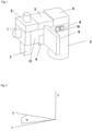
- Figure 1 schematically depicts a portable survey meter according to an embodiment of the invention.
- Figure 2 schematically depicts the scanning plane of a LIDAR of a portable survey meter according to an embodiment of the invention.
- Figure 1 schematically depicts a portable survey meter according to an embodiment of the invention.
- the portable survey meter is for checking for radioactive contamination.
- the portable survey meter can be used in a method for collecting spatially registered radiological measurements.
- the portable survey meter comprises a radiation detector 7.
- the radiation detector 7 is configured to perform measurements (e.g. radiological measurements) of ionising radiation.
- the radiation detector 7 is a means of measuring the level of ionising radiation. Additionally, the radiation detector 7 is configured to perform measurements of non-ionising radiation.
- the portable survey meter comprises a range sensor 1, 2.
- the range sensor 1, 2 is configured to measure range data of distances from the portable survey meter to real world structures in at least two dimensions.
- the range data is interpreted by an algorithm to determine an instantaneous position of the portable survey meter in at least two dimensions relative to the real world structures as a fixed frame of reference.
- the range sensor combines with software running the algorithm to determine the position of the portable survey meter relative to the real world structures. Accordingly, each radiological measurement is performed at a known position.
- the range sensor 1, 2 combined with the software is a means of determining the instantaneous position of the portable survey meter (which may also be called a detector) in a least two dimensions relative to real world structures surrounding the portable survey meter.
- Each range sensor 1, 2 is configured to measure the distance (i.e. range) from the portable survey meter to a real world object, such as a wall.
- the range sensor 1, 2 is configured to measure time-varying range data about how far the portable survey meter is from real world structures in different directions.
- the first range sensor 1 is configured to measure the range to real world objects in the XY plane.
- the range data is then used to determine the position of the portable survey meter to the real world objects. This can be done by aligning the range data to known information about the real world structures.
- the range data may provide information about the distance from the portable survey meter to a series of points of a room.
- the position of the portable survey meter can then be determined by aligning the range data to a map of the room.
- the map of the room is an example of known information about the layout of the real world structures.
- the measured range data is interpreted to provide positional information relative to the real world structures. This interpretation is performed by software that runs an algorithm configured to deduce the motion of the portable survey meter by aligning the range data with reference range data (e.g. a map).
- the position of the portable survey meter can be determined relative to the real world structures as the fixed frame of reference. This is different from other means of detecting position such as GPS, radio beacon methods and QR code readers.
- GPS, radio beacon methods and QR code readers rely on measuring the distance to satellites, beacons or QR codes that have a known position in a coordinate system.
- the position of the reader can be determined by measuring the distance to multiple satellites, beacons or QR codes and solving equations to determine the position of the reader within that coordinate system. These methods do not involve aligning the measured distances to the satellites, beacons or QR codes to reference range data.
- the invention does not require any real world objects to be installed for the purpose of position determination.
- the invention does not require any satellite, beacon or QR code.
- the real world structures are not satellites, beacons or QR codes.
- the range sensor 1, 2 measures the range to objects that just happened to be there.
- the position of the objects in another coordinate system is not required to be known.
- the measured range data is aligned with the reference range data so that the real world structures themselves become the fixed frame of reference.
- Alignment of range data may be achieved by any algorithm which is capable of calculating a transform between the current range data and one or more examples of reference range data. It is preferable in the present application that such algorithms be designed to keep computation demands to a minimum in order that the physical space and power requirements of the radiation measurement device can be kept low.
- An algorithm which is particularly suitable for aligning horizontal-plane range data is described:
- step 2 will also work for vertical lidar data if step 2 is restricted to a the vertical dimension only.
- the algorithm is limited to the case where the current data overlaps significantly with the reference data.
- the algorithm can be extended by introducing the concept of a key-frame.
- the current range data is found to be offset from the reference data by some predetermined distance threshold, or when the similarity score drops beneath a predetermined threshold, the current frame is nominated as a 'key-frame'.
- Subsequent range data will be registered to the most recent fey-frame rather than the original reference data.
- the alignment between the original reference data and the current data can then be deduced by combining the transform between the current data and the current key-frame with the transform between the current key-frame and the reference frame (which may itself depend on the transforms of other intermediate key-frames).
- the portable survey meter comprises a means of continuously recording spatial data such that a 3D model can be generated as the portable survey meter is moved around the area.
- the measurement of radiological and geometrical data may be achieved using a combination of sensors (e.g. the radiation detector 7 and the range sensor 1, 2).
- the sensors that provide the geometrical data may be configured to determine the location and orientation of the portable survey meter in six degrees of freedom relative to real world structures. However, this is not necessarily the case.
- the sensors that provide the geometrical data may be configured to determine the location of the portable survey meter in two degrees of freedom (e.g. in a horizontal plane), three degrees of freedom (e.g. in a horizontal plane and a vertical plane), four degrees of freedom (e.g. in a horizontal plane and a vertical plane and the yaw of the portable survey meter) or five degrees of freedom (e.g. in a horizontal plane and a vertical plane and the pitch and yaw of the portable survey meter).
- the portable survey meter optionally comprises two range sensors 1, 2. However, this is not necessarily the case. In alternative embodiments the portable survey meter comprises only one range sensor 1, or more than two range sensors.
- the first range sensor 1 is configured to measure range data of distances from the portable survey meter to real world structures in the horizontal (XY) plane.
- the range sensor 1, 2 is configured to measure the range data using Light Detection and Ranging (LIDAR), Sound Navigation and Ranging (SONAR) or Radio Detection and Ranging (RADAR).
- LIDAR Light Detection and Ranging
- SONAR Sound Navigation and Ranging
- RADAR Radio Detection and Ranging
- the first range sensor 1 could be a LIDAR instrument, a SONAR instrument or a RADAR instrument.
- the first range sensor 1 is capable of measuring the distance from the portable survey meter to real world structures, surrounding the portable survey meter.
- the LIDAR instrument is configured to rotate around the Z axis making an angle theta to the X axis, shown in Figure 2 .
- the first range sensor 1 is configured to scan the XY plane, making a series of measurements of the distance at angle theta to the nearest surface based on the time of flight of laser pulses emitted by the LIDAR instrument and reflected off the surface. Change in position of the portable survey meter over time can be measured by calculating the translation and rotation that best aligns the current range data with the previous (e.g. initial) range data.
- the reference range data to which measured rage data is aligned may be the initial range data measured when a survey is started. Hence, it is not necessary for a map of the region to be surveyed to be known. Even without such a map it is possible for a model of the region to be built up during the survey.
- the survey meter of the present invention is designed to be portable.
- the portable survey meter could be hand held.
- the portable survey meter may move vertically.
- the portable survey meter may be tilted, giving a false impression of the surrounding world.
- the output from the first range sensor 1 (which may also be called a horizontal position measurement device) is corrected for tilt as described below.
- the portable survey meter comprises an orientation detector 3.
- the orientation detector 3 is configured to determine at least one of an instantaneous yaw, an instantaneous roll and an instantaneous pitch of the portable survey meter relative to the real world structures.
- the orientation detector 3 is configured to measure the tilt of the portable survey meter such that a correction factor can be applied to the XY data to ensure it represents a more accurately horizontal plane.
- the orientation detector is an Inertial Measurement Unit (EMU) configured to measure at least six degrees of freedom.
- the portable survey meter comprises a magnetometer for improved orientation accuracy.
- the portable survey meter comprises a mechanical stabiliser device.
- the mechanical stabiliser device is fitted to the rest of the portable survey meter so as to prevent or reduce any tilt.
- the portable survey meter comprises a positional feedback provider.
- the positional feedback provider is configured to output to a user information to help the user move the portable survey meter to a target position and/or orientation relative to the real world structures.
- the positional feedback provider is configured to output to the user information to help the user change at least one of the yaw, the roll and the pitch of the portable survey meter to a target yaw, a target roll and a target pitch, respectively, relative to the real world structures.
- the positional feedback provider is configured to provide feedback to allow the user to manually correct for any tilt.
- an IMU is used as the orientation detector 3
- the instantaneous pitch, roll and yaw of the portable survey meter can be measured such that, when combined with the data measured by the first range sensor 1, five of the six degrees of freedom are known (X,Y, pitch, roll and yaw).
- the portable survey meter comprises a processing unit 4 (also called a main processing unit).
- a processing unit 4 also called a main processing unit.
- the processing unit 4 is configured to calculate the height of the portable survey meter based on the angle of the portable survey meter as measured by the orientation detector 3.
- the second range sensor 2 is rigidly attached to the first range sensor 1.
- the data output by the range sensor 1, 2 can be used to build a 3D model.
- the processing unit 4 is configured to receive range data from the first range sensor 1 and, if the second range sensor 2 is provided, also from the second range sensor 2.
- the processing unit 4 is configured to compare the range data with previous range data (possibly the initial range data).
- the processing unit 4 is configured to calculate the translation and rotation that best aligns the current range data with the previous (e.g. initial) range data so as to measure a change in position and/or orientation of the portable survey meter over time.
- the processes of comparing the range data and calculating the translation and rotation to measure the change in position may be performed by a processor that is positioned remotely from the portable survey meter.
- the portable survey meter comprises a height detector configured to determine an instantaneous height of the portable survey meter above a floor.
- the height detector is a sensor that directly measures a property that changes predictably with changes of position in the Z direction.
- the portable survey meter comprises a barometric pressure sensor.
- Radiological data is collected using a suitable radiation detector 7, for example a Geiger-Muller tube, a total count detector or a scintillator.
- the types of radiation that are measured may not be limited to gamma rays but may be any type or types of ionising or non-ionising radiation.
- the device collects a series of measurements of the radiation field at registered positions, determined by the range sensor 1, 2 and software described above.
- the radiation detector 7 is rigidly attached the range sensor 1, 2.
- the output from each of the range sensor 1, 2, the software and the radiation detector 7 provides a two or three dimensional model of the facility, a series of radiation measurements and a set of coordinates (optionally corrected for the orientation of the portable survey meter) that describe the location of each radiation measurement within the model.
- the portable survey meter comprises a local memory.
- the local memory is configured to record the position of the portable survey meter at which each radiological measurement was performed in association with the radiological measurement. This information is stored on-board the portable survey meter on a suitable storage device such that it can be retrieved at a later time for further processing or manipulation.
- the portable survey meter comprises a data uploader.
- the data uploader is configured to send information indicating each radiological measurement and the position of the portable survey meter at which the radiological measurement was performed to an external memory.
- the optional final stage in the process is to utilise the information gathered by the portable survey meter described above to predict the distribution of radioactive sources within the facility. To do this the method outlined in European patent 2074442 could be used.
- the portable survey meter illustrated in Figure 1 is an apparatus that comprises two LIDAR sensors mounted such that one scans the XZ vertical plane while the other scans the XY horizontal plane, as the range sensors 1, 2. It is not essential to have two range sensors 1, 2.
- the portable survey meter comprises only one range sensor 1, such that the position of the portable survey meter can be determined in two dimension (i.e. in the XY plane).
- the portable survey meter comprises a height detector configured to measure the height of the portable survey meter.
- LIDAR data is used to improve the accuracy and stability of roll correction as follows: during each scan a histogram is made of the vectors between successive LIDAR echoes.
- SONAR, RADAR or other forms of scanning or staring distance measurement sensors may be used.
- a Geiger-Muller tube is used as the radiation detector 7 (also called a radiometric sensor) in this embodiment.
- the radiation detector 7 may be, for example, an uncollimated total-counts gamma radiation sensor, an un-collimated total absorbed dose radiation sensor or any other type of radiation detector as required by the application.
- the radiation detector 7 is configured to perform a radiological measurement by detecting an amount of radiation received from any direction over a predetermined time period.
- the radiation detected by the radiation detector 7 is not limited to gamma radiation but may be any type or types of ionising
- the radiation detector 7, the range sensors 1, 2 and the orientation detector 3 are mounted together.
- the portable survey meter comprises a frame 11.
- the radiation detector 7, the range sensors 1, 2 and the orientation detector 3 may be mounted on the frame 11, so that they are fixed relative to each other.
- the frame 11 can be hand-held.
- the frame 11 may be mounted on a remote deployment platform, for example a long pole or a remotely operated vehicle, such as a remotely controllable platform with robotic arm, or a quadcopter. This may be particularly advantageous if deployment is required in a region where expected radiation levels are too high to permit human entry.
- the portable survey meter comprises a positional feedback provider.
- the portable survey meter comprises a display 8, which may form part of the positional feedback provider.
- the display 8 may be mounted to the frame 11 so that the display 8 can display instructions directing the user to the next target position (i.e. measurement point).
- the positional feedback provider is configured to output to the user information to help the user change the height of the portable survey meter to a target height relative to the floor.
- the radiation detector 7 is configured to automatically perform a radiological measurement when the difference between the instantaneous position of the portable survey meter and a target position is less than a threshold positional difference. In other words, the measurement is triggered automatically once the portable survey meter is sufficiently close to the intended location (i.e. the target position). However, it is not necessary for the measurement to be performed automatically.
- the portable survey meter comprises an input device configured to allow a user to instruct the radiation detector 7 to perform a radiological measurement at the current position of the portable survey meter.
- the input device is a trigger 10.
- the trigger 10 is provided so that once at the correct location the user can provide an input causing the portable survey meter to take a spatially tagged radiation measurement.
- the measurement could be triggered by other means of user input.
- the radiation detector 7 is configured to perform a radiological measurement simultaneously with the range sensor 1, 2 combined with the software determining the instantaneous position of the portable survey meter. Accordingly, each radiation measurement is spatially tagged. Each radiation measurement is stored together with information regarding the position and optionally orientation of the portable survey meter.
- the portable survey meter comprises a handle 5.
- the handle makes it easier for a user to hold the portable survey meter steadily while moving around a facility to take a survey.
- the portable survey meter comprises a battery 6.
- the battery 6 is provided as a power source for the portable survey meter.
- the portable survey meter comprises a switch 9.
- the switch 9 is a power switch for the portable survey meter.
- the portable survey meter is taken to the facility to be modelled and is switched on using switch 9. On completion of the power-up sequence, surveying may be started automatically.
- the portable survey meter starts to record positional data as follows: the range sensors 1, 2 record distances to real-world structures within their respective measurement planes and the orientation detector 3 records relative position and orientation continuously.
- This data is stored on a storage medium within the processing unit 4 and is also processed in real time using an algorithm to build up a 2D model of the surveyed region.
- the processing unit 4 comprises the software that is configured to align the measured range data with reference range data so as to determine the instantaneous position of the portable survey meter in at least two dimensions relative to the real world structures as a fixed frame of reference.
- the Manhattan world assumption that structures appear little different from observation points closely spaced along the Z axis, is used in processing. This model is held in the processing unit 4.
- the processing unit 4 is also loaded up with a series of target positions (i.e. a set of survey locations) relative to the facility structure.
- the portable survey meter comprises a target position setting unit, which may be embodied in the processing unit 4.
- the target position setting unit is configured to set a new target position from among the series of target positions after the radiation detector 7 has performed the radiological measurement at the target position.
- the target position setting unit is configured to set a new target position from among the series of target positions upon instruction from a user to skip the target position.
- the order of measurements might be unimportant and the portable survey meter might direct the user to the closest measurement point rather than the next in sequence.
- a measurement is made automatically or on demand based on the user pressing the trigger 10.
- Embodiments may feature a software interlock to prevent the measurement being taken when the unit is too far from the survey point, or they may eliminate the user input in favour of having the measurement triggered automatically when the sensor is within an acceptable distance of the required survey location.
- the radiation detector 7 is configured to automatically perform a radiological measurement when the difference between the instantaneous position of the portable survey meter and a target position is less than a threshold positional difference and the difference between the at least one of the instantaneous yaw, the instantaneous roll and the instantaneous pitch of the portable survey meter and a target yaw, a target roll and a target pitch, respectively, is less than a threshold yaw difference, a threshold roll difference and a threshold pitch difference, respectively.
- the radiation detector 7 is configured to automatically perform a radiological measurement when the difference between the instantaneous position of the portable survey meter and a target position is less than a threshold positional difference and the difference between the instantaneous height of the portable survey meter and a target height is less than a threshold height difference.
- Embodiments may provide visual, audio or other sensory feedback to the operator to indicate the progress and completion of the measurement.
- each radiation measurement is completed it is tagged with a location, relative to the 2D region model, calculated from the LIDAR sensors and IMU, and stored in the storage attached to the processing unit 4.
- the facility could be a single room, multiple rooms in a building, the exterior surface of building walls or indeed any three dimensional environment containing unknown distribution of radioactive material in which it is possible to determine location and orientation using the inbuilt geometric sensors, i.e. the range sensors 1, 2 and the orientation detector 3.
- the general term "region" is used for any such facility or space for which it is intended to determine the distribution of radioactive material.
- the number of observations required will be determined by the operator's survey requirements but the automated spatial registration and user feedback provided by the unit facilitate the recording of a larger number of survey points in the same time when compared to existing manual techniques.
- the data as collected provides dose information at a number of locations within the surveyed region. This data is similar in nature to that obtained by a manually conducted radiation survey in which the location of each measurement is simply marked approximately on a floor plan of the facility, but by using this embodiment of the invention the spatial location of each measurement is recorded much more accurately than traditional radiation surveys allow.
Landscapes
- Physics & Mathematics (AREA)
- Engineering & Computer Science (AREA)
- Radar, Positioning & Navigation (AREA)
- Remote Sensing (AREA)
- General Physics & Mathematics (AREA)
- Computer Networks & Wireless Communication (AREA)
- Electromagnetism (AREA)
- Health & Medical Sciences (AREA)
- Life Sciences & Earth Sciences (AREA)
- High Energy & Nuclear Physics (AREA)
- Molecular Biology (AREA)
- Spectroscopy & Molecular Physics (AREA)
- Acoustics & Sound (AREA)
- Measurement Of Radiation (AREA)
- Telephone Function (AREA)
Claims (15)
- Tragbare Messvorrichtung zur Messung ionisierender Strahlung, wobei die tragbare Messvorrichtung Folgendes umfasst:einen Strahlungsdetektor (7), der dafür konfiguriert ist, Messungen von ionisierender Strahlung durchzuführen; undeinen Entfernungssensor (1, 2), der dafür konfiguriert ist, Entfernungsdaten von Entfernungen von der tragbaren Messvorrichtung zu realen Strukturen in mindestens zwei Dimensionen zu messen;gekennzeichnet durch eine Verarbeitungseinheit (4), die dafür konfiguriert ist, die gemessenen Entfernungsdaten mit Referenzentfernungsdaten der realen Strukturen abzugleichen, so dass eine momentane Position der tragbaren Messvorrichtung in mindestens zwei Dimensionen relativ zu den Strukturen der realen Welt als ein fester Referenzrahmen bestimmt wird, wodurch jede Messung an einer bekannten Position durchgeführt wird,wobei die Verarbeitungseinheit dafür konfiguriert ist, eine Translation und Rotation zu berechnen, die die gemessenen Entfernungsdaten am besten mit zuvor gemessenen Entfernungsdaten abgleicht, um eine Änderung der Position und/oder Ausrichtung der tragbaren Messvorrichtung im Laufe der Zeit zu messen.
- Tragbare Messvorrichtung nach Anspruch 1, wobei der Strahlungsdetektor dafür konfiguriert ist, eine Messung gleichzeitig mit einer Software durchzuführen, die die momentane Position der tragbaren Messvorrichtung bestimmt.
- Tragbare Messvorrichtung nach einem der vorhergehenden Ansprüche, die Folgendes umfasst:einen Positionsrückmeldungsanbieter, der dafür konfiguriert ist, Informationen an einen Benutzer auszugeben, die dem Benutzer helfen, die tragbare Messvorrichtung in eine Zielposition relativ zu den Strukturen der realen Welt zu bewegen.
- Tragbare Messvorrichtung nach einem der vorhergehenden Ansprüche, wobei der Strahlungsdetektor dafür konfiguriert ist, automatisch eine Messung durchzuführen, wenn die Differenz zwischen der momentanen Position der tragbaren Messvorrichtung und einer Zielposition kleiner als eine Schwellenwert-Positionsdifferenz ist, optional umfassend:eine Zielpositionseinstelleinheit, die dafür konfiguriert ist, eine neue Zielposition aus einer Reihe von Zielpositionen einzustellen, nachdem der Strahlungsdetektor die Messung an der Zielposition durchgeführt hat, wobei die Zielpositionseinstelleinheit optional dafür konfiguriert ist, eine neue Zielposition aus der Reihe der Zielpositionen auf Anweisung eines Benutzers, die Zielposition zu überspringen, einzustellen.
- Tragbare Messvorrichtung nach einem der vorhergehenden Ansprüche, wobei:der Entfernungssensor dafür konfiguriert ist, die Entfernungsdaten unter Verwendung von LID AR, SONAR oder RADAR zu messen; und/oderdie tragbare Messvorrichtung eine Eingabevorrichtung (10) umfasst, die dafür konfiguriert ist, es einem Benutzer zu ermöglichen, den Strahlungsdetektor anzuweisen, eine Messung an der aktuellen Position der tragbaren Messvorrichtung durchzuführen.
- Tragbare Messvorrichtung nach einem der vorhergehenden Ansprüche, die Folgendes umfasst:einen Orientierungsdetektor (3), der dafür konfiguriert ist, mindestens eines von einem momentanen Gieren, einem momentanen Rollen und einem momentanen Nicken der tragbaren Messvorrichtung relativ zu den Strukturen der realen Welt zu bestimmen.
- Tragbare Messvorrichtung nach Anspruch 6 in Abhängigkeit von Anspruch 3, wobei der Positionsrückmeldungsanbieter dafür konfiguriert ist, Informationen an den Benutzer auszugeben, um dem Benutzer zu helfen, mindestens eines der Folgenden zu ändern: das Gieren, das Rollen und das Nicken der tragbaren Messvorrichtung zu einem Zielgieren, einem Zielrollen bzw. einem Zielnicken relativ zu den realen Strukturen.
- Tragbare Messvorrichtung nach Anspruch 6 oder 7, wobei der Strahlungsdetektor dafür konfiguriert ist, automatisch eine Messung durchzuführen, wenn die Differenz zwischen der momentanen Position der tragbaren Messvorrichtung und einer Zielposition kleiner als eine Schwellenwert-Positionsdifferenz ist und die Differenz zwischen dem momentanen Gieren, dem momentanen Rollen und dem momentanen Nicken der tragbaren Messvorrichtung und einem Zielgieren, einem Zielrollen bzw. einem Zielnicken kleiner ist als eine Schwellenwert-Gierdifferenz, eine Schwellenwert-Rolldifferenz bzw. eine Schwellenwert-Nickdifferenz.
- Tragbare Messvorrichtung nach einem der vorhergehenden Ansprüche, die Folgendes umfasst:einen Höhendetektor, der dafür konfiguriert ist, eine momentane Höhe der tragbaren Messvorrichtung über einem Boden zu bestimmen.
- Tragbare Messvorrichtung nach Anspruch 9 in Abhängigkeit von Anspruch 3, wobei der Positionsrückmeldungsanbieter dafür konfiguriert ist, Informationen an den Benutzer auszugeben, um dem Benutzer zu helfen, die Höhe der tragbaren Messvorrichtung auf eine Zielhöhe relativ zum Boden zu ändern.
- Tragbare Messvorrichtung nach Anspruch 9 oder 10, wobei der Strahlungsdetektor dafür konfiguriert ist, automatisch eine Messung durchzuführen, wenn die Differenz zwischen der momentanen Position der tragbaren Messvorrichtung und einer Zielposition kleiner als eine Schwellenwert-Positionsdifferenz ist und die Differenz zwischen der momentanen Höhe der tragbaren Messvorrichtung und einer Zielhöhe kleiner als eine Schwellenwert-Höhendifferenz ist.
- Tragbare Messvorrichtung nach einem der vorhergehenden Ansprüche, wobei:der Strahlungsdetektor dafür konfiguriert ist, eine Messung durch Erfassen einer Strahlungsmenge durchzuführen, die aus einer beliebigen Richtung über einen vorbestimmten Zeitraum empfangen wird; und/oderdie tragbare Messvorrichtung einen lokalen Speicher umfasst, der dafür konfiguriert ist, die Position der tragbaren Messvorrichtung, an der jede Strahlungsmessung durchgeführt wurde, in Verbindung mit der Strahlungsmessung aufzuzeichnen; und/oderdie Verarbeitungseinheit dafür konfiguriert ist, die gemessenen Entfernungsdaten mit den Referenzentfernungsdaten in Echtzeit abzugleichen, um ein Modell eines untersuchten Bereichs aufzubauen, wobei das Modell in mindestens zwei Dimensionen vorliegt.
- Tragbare Messvorrichtung nach einem der vorhergehenden Ansprüche, die Folgendes umfasst:eine Anzeige (8), die dafür konfiguriert ist, dem Benutzer das Modell anzuzeigen;
odereine Anzeige (8), die dafür konfiguriert ist, Informationen an einen Benutzer auszugeben, um die momentane Position der tragbaren Messvorrichtung innerhalb des festen Referenzrahmens anzuzeigen. - Tragbare Messvorrichtung nach einem der vorhergehenden Ansprüche, wobei:die tragbare Messvorrichtung in der Hand gehalten wird; und/oderder Strahlungsdetektor dafür konfiguriert ist, Messungen der Umgebungsstrahlung durchzuführen; und/oderdie tragbare Messvorrichtung einen Daten-Uploader umfasst, der dafür konfiguriert ist, Informationen, die jede Messung und die Position der tragbaren Messvorrichtung, an der die Messung durchgeführt wurde, angeben, an einen externen Speicher zu senden.
- Verfahren zur Messung ionisierender Strahlung, wobei das Verfahren Folgendes umfasst:Durchführen von Messungen der ionisierenden Strahlung unter Verwendung einer tragbaren Messvorrichtung; undMessen von Entfernungsdaten von Entfernungen von der tragbaren Messvorrichtung zu realen Strukturen in mindestens zwei Dimensionen;gekennzeichnet durch Ausrichten der gemessenen Entfernungsdaten mit Referenzentfernungsdaten der realen Strukturen, so dass die momentane Position der tragbaren Messvorrichtung in mindestens zwei Dimensionen relativ zu den Strukturen der realen Welt als ein fester Referenzrahmen bestimmt wird, wodurch jede Messung an einer bekannten Position durchgeführt wird,wobei das Verfahren das Berechnen einer Translation und Rotation umfasst, die die gemessenen Entfernungsdaten am besten mit zuvor gemessenen Entfernungsdaten ausrichtet, um eine Änderung der Position und/oder Ausrichtung der tragbaren Messvorrichtung im Laufe der Zeit zu messen.
Applications Claiming Priority (2)
| Application Number | Priority Date | Filing Date | Title |
|---|---|---|---|
| GBGB1611429.0A GB201611429D0 (en) | 2016-06-30 | 2016-06-30 | Portable survey meter and method |
| PCT/GB2017/051935 WO2018002657A1 (en) | 2016-06-30 | 2017-06-30 | Portable survey meter and method |
Publications (2)
| Publication Number | Publication Date |
|---|---|
| EP3479143A1 EP3479143A1 (de) | 2019-05-08 |
| EP3479143B1 true EP3479143B1 (de) | 2022-03-09 |
Family
ID=56891062
Family Applications (1)
| Application Number | Title | Priority Date | Filing Date |
|---|---|---|---|
| EP17737026.9A Active EP3479143B1 (de) | 2016-06-30 | 2017-06-30 | Tragbares strahlungsmessgerät und verfahren |
Country Status (8)
| Country | Link |
|---|---|
| US (1) | US10962658B2 (de) |
| EP (1) | EP3479143B1 (de) |
| JP (1) | JP7137482B2 (de) |
| CN (1) | CN109690354B (de) |
| CA (1) | CA3028579C (de) |
| ES (1) | ES2918126T3 (de) |
| GB (1) | GB201611429D0 (de) |
| WO (1) | WO2018002657A1 (de) |
Families Citing this family (7)
| Publication number | Priority date | Publication date | Assignee | Title |
|---|---|---|---|---|
| US20210247506A1 (en) * | 2020-02-12 | 2021-08-12 | Aptiv Technologies Limited | System and method of correcting orientation errors |
| CN113311470B (zh) * | 2021-05-27 | 2023-01-10 | 华能山东石岛湾核电有限公司 | 一种电离辐射测量装置及其测量方法 |
| CN116242804B (zh) * | 2023-05-09 | 2023-08-15 | 四川威斯派克科技有限公司 | 一种便携式近红外光谱仪 |
| CN118247427B (zh) * | 2024-03-07 | 2025-04-08 | 北京疆泰科技有限公司 | 辐射风险信息的处理方法和装置 |
| CN119959175A (zh) * | 2025-02-25 | 2025-05-09 | 中国建筑科学研究院有限公司 | 一种便携式无损检测傅里叶变换红外光谱仪 |
| KR102942944B1 (ko) | 2025-11-12 | 2026-03-25 | (주)일진라드 | 가이거 뮐러 튜브형 검출 부재가 적용된 휴대용 방사선 측정 장치 |
| KR102942945B1 (ko) * | 2025-11-12 | 2026-03-25 | (주)일진라드 | 가이거 뮐러 튜브형 휴대용 방사선 측정 장치에 적용되는 검출 부재 결합 유닛 |
Family Cites Families (29)
| Publication number | Priority date | Publication date | Assignee | Title |
|---|---|---|---|---|
| JPH03163390A (ja) * | 1989-11-22 | 1991-07-15 | Haruo Fujii | 自走式放射性物質自動測定表示装置 |
| US5286973A (en) | 1991-11-13 | 1994-02-15 | Odetics, Inc. | Radiation mapping system |
| JPH09113627A (ja) | 1995-10-16 | 1997-05-02 | Toshiba Corp | 放射線源強度測定装置 |
| US6628984B2 (en) * | 2000-04-12 | 2003-09-30 | Pem Technologies, Inc. | Hand held camera with tomographic capability |
| JP2002174518A (ja) * | 2000-12-06 | 2002-06-21 | Taisei Corp | 自動測量システム |
| GB0128361D0 (en) * | 2001-11-27 | 2002-01-16 | British Nuclear Fuels Plc | Improvements in and relating to instruments |
| US7142634B2 (en) * | 2003-01-29 | 2006-11-28 | New England Medical Center Hospitals, Inc. | Radiation field detection |
| WO2006010772A1 (en) * | 2004-07-28 | 2006-02-02 | Target Systemelectronic Gmbh | Cryogenic cooling device |
| US8217362B2 (en) * | 2005-04-28 | 2012-07-10 | Utah State University | Identification and localization of radioisotopes using likelihood estimation |
| US7897932B2 (en) | 2005-04-28 | 2011-03-01 | Utah State University | Identification and localization of radioisotopes |
| WO2007030026A1 (en) | 2005-09-09 | 2007-03-15 | Industrial Research Limited | A 3d scene scanner and a position and orientation system |
| JP2011133467A (ja) * | 2009-11-30 | 2011-07-07 | Atc:Kk | 放射線強度分布又は吸収線量分布を測定する方法、装置及びプログラム |
| EP2622608A2 (de) | 2010-08-18 | 2013-08-07 | Savannah River Nuclear Solutions, LLC | System und verfahren zur identifizierung von strahlung in kontaminierten räumen |
| US8519343B1 (en) * | 2011-04-25 | 2013-08-27 | U.S. Department Of Energy | Multimode imaging device |
| TWI443362B (zh) * | 2011-04-29 | 2014-07-01 | Nat Applied Res Laboratoires | 不可見光粒子檢測裝置 |
| JP5666716B2 (ja) * | 2011-10-26 | 2015-02-12 | 富士フイルム株式会社 | 放射線動画処理装置、放射線動画撮影装置、放射線動画撮影システム、放射線動画処理方法、放射線動画処理プログラム、及び記憶媒体 |
| GB201120168D0 (en) * | 2011-11-23 | 2012-01-04 | Kromek Ltd | Portable detector apparatus |
| EP2620746A1 (de) * | 2012-01-30 | 2013-07-31 | Hexagon Technology Center GmbH | Vermessungsgerät mit Scanfunktionalität und Einzelpunktmessmodus |
| CA3228582A1 (en) * | 2012-03-07 | 2013-09-12 | Ziteo, Inc. | Methods and systems for tracking and guiding sensors and instruments |
| JP2014071013A (ja) | 2012-09-28 | 2014-04-21 | Toshiba Corp | 放射線管理装置、放射線管理システム、放射線管理方法および放射線管理プログラム |
| US9513107B2 (en) | 2012-10-05 | 2016-12-06 | Faro Technologies, Inc. | Registration calculation between three-dimensional (3D) scans based on two-dimensional (2D) scan data from a 3D scanner |
| AR090205A1 (es) * | 2013-02-28 | 2014-10-29 | Invap S E | Dispositivo para la deteccion y control del trafico ilicito de materiales nucleares especiales |
| JP2014185967A (ja) | 2013-03-25 | 2014-10-02 | Hitachi Ltd | 移動式線量計測装置 |
| US8825260B1 (en) | 2013-07-23 | 2014-09-02 | Google Inc. | Object and ground segmentation from a sparse one-dimensional range data |
| FR3009881B1 (fr) * | 2013-08-23 | 2017-03-17 | Stmi Soc Des Techniques En Milieu Ionisant | Modelisation 3d topographique et radiologique d'un environnement |
| US9791391B2 (en) * | 2013-09-24 | 2017-10-17 | Oxford Instruments Industrial Analysis Oy | Portable analyzer with radiation safety features |
| US20150237419A1 (en) * | 2014-02-18 | 2015-08-20 | Senaya, Inc. | Radiation exposure monitoring device and system |
| FR3052858B1 (fr) * | 2016-06-21 | 2020-04-03 | Thales | Procede d'estimation d'une direction d'orientation absolue d'un systeme optronique |
| US11199631B2 (en) * | 2017-04-07 | 2021-12-14 | Criterionix, L.L.C. | Apparatus and methods for geo-locating one or more objects |
-
2016
- 2016-06-30 GB GBGB1611429.0A patent/GB201611429D0/en not_active Ceased
-
2017
- 2017-06-30 CN CN201780040811.6A patent/CN109690354B/zh active Active
- 2017-06-30 WO PCT/GB2017/051935 patent/WO2018002657A1/en not_active Ceased
- 2017-06-30 EP EP17737026.9A patent/EP3479143B1/de active Active
- 2017-06-30 ES ES17737026T patent/ES2918126T3/es active Active
- 2017-06-30 CA CA3028579A patent/CA3028579C/en active Active
- 2017-06-30 JP JP2018568351A patent/JP7137482B2/ja active Active
-
2018
- 2018-12-17 US US16/222,612 patent/US10962658B2/en active Active
Non-Patent Citations (1)
| Title |
|---|
| None * |
Also Published As
| Publication number | Publication date |
|---|---|
| JP7137482B2 (ja) | 2022-09-14 |
| GB201611429D0 (en) | 2016-08-17 |
| CN109690354B (zh) | 2023-08-04 |
| CN109690354A (zh) | 2019-04-26 |
| ES2918126T3 (es) | 2022-07-13 |
| WO2018002657A1 (en) | 2018-01-04 |
| US10962658B2 (en) | 2021-03-30 |
| EP3479143A1 (de) | 2019-05-08 |
| US20190154846A1 (en) | 2019-05-23 |
| CA3028579A1 (en) | 2018-01-04 |
| JP2019525153A (ja) | 2019-09-05 |
| CA3028579C (en) | 2025-05-13 |
Similar Documents
| Publication | Publication Date | Title |
|---|---|---|
| US10962658B2 (en) | Portable survey meter and method | |
| EP3479142B1 (de) | Strahlungsabbildungsvorrichtung | |
| US8532368B2 (en) | Method and apparatus for producing 3D model of an environment | |
| US20140132729A1 (en) | Method and apparatus for camera-based 3d flaw tracking system | |
| US10733330B2 (en) | 3D topographic and radiological modeling of an environment | |
| US8510039B1 (en) | Methods and apparatus for three-dimensional localization and mapping | |
| US7627448B2 (en) | Apparatus and method for mapping an area of interest | |
| US20150130928A1 (en) | Point-to-point measurements using a handheld device | |
| EP3916422A1 (de) | Erfassung von umgebungsabtastungen unter verwendung von landmarken basierend auf semantischen merkmalen | |
| Chung et al. | Development of LiDAR simulator for backpack-mounted mobile indoor mapping system | |
| Martino et al. | Affordable sensors for speditive and accurate documentation of built heritage: first tests and preliminary results | |
| US12157050B2 (en) | Sports field marking equipment | |
| CA3028576C (en) | Radiation imaging apparatus | |
| EP4231053A1 (de) | Ausrichten von scans einer umgebung unter verwendung eines referenzobjekts | |
| US20220018950A1 (en) | Indoor device localization | |
| JP2024518862A (ja) | 施工検証システム、方法およびコンピュータプログラム製品 | |
| JP7505867B2 (ja) | 画像位置特定装置、方法およびプログラム、並びに温度管理システム | |
| Mitka et al. | Procedure and Accuracy Assessment Results of Livox MID-360 Scanners | |
| Yan | A Study on Augmented Reality for Supporting |
Legal Events
| Date | Code | Title | Description |
|---|---|---|---|
| STAA | Information on the status of an ep patent application or granted ep patent |
Free format text: STATUS: UNKNOWN |
|
| STAA | Information on the status of an ep patent application or granted ep patent |
Free format text: STATUS: THE INTERNATIONAL PUBLICATION HAS BEEN MADE |
|
| PUAI | Public reference made under article 153(3) epc to a published international application that has entered the european phase |
Free format text: ORIGINAL CODE: 0009012 |
|
| STAA | Information on the status of an ep patent application or granted ep patent |
Free format text: STATUS: REQUEST FOR EXAMINATION WAS MADE |
|
| 17P | Request for examination filed |
Effective date: 20181220 |
|
| AK | Designated contracting states |
Kind code of ref document: A1 Designated state(s): AL AT BE BG CH CY CZ DE DK EE ES FI FR GB GR HR HU IE IS IT LI LT LU LV MC MK MT NL NO PL PT RO RS SE SI SK SM TR |
|
| AX | Request for extension of the european patent |
Extension state: BA ME |
|
| DAV | Request for validation of the european patent (deleted) | ||
| DAX | Request for extension of the european patent (deleted) | ||
| STAA | Information on the status of an ep patent application or granted ep patent |
Free format text: STATUS: EXAMINATION IS IN PROGRESS |
|
| 17Q | First examination report despatched |
Effective date: 20200624 |
|
| GRAP | Despatch of communication of intention to grant a patent |
Free format text: ORIGINAL CODE: EPIDOSNIGR1 |
|
| STAA | Information on the status of an ep patent application or granted ep patent |
Free format text: STATUS: GRANT OF PATENT IS INTENDED |
|
| INTG | Intention to grant announced |
Effective date: 20210920 |
|
| RAP3 | Party data changed (applicant data changed or rights of an application transferred) |
Owner name: CREATE TECHNOLOGIES LIMITED |
|
| GRAS | Grant fee paid |
Free format text: ORIGINAL CODE: EPIDOSNIGR3 |
|
| GRAA | (expected) grant |
Free format text: ORIGINAL CODE: 0009210 |
|
| STAA | Information on the status of an ep patent application or granted ep patent |
Free format text: STATUS: THE PATENT HAS BEEN GRANTED |
|
| AK | Designated contracting states |
Kind code of ref document: B1 Designated state(s): AL AT BE BG CH CY CZ DE DK EE ES FI FR GB GR HR HU IE IS IT LI LT LU LV MC MK MT NL NO PL PT RO RS SE SI SK SM TR |
|
| REG | Reference to a national code |
Ref country code: CH Ref legal event code: EP Ref country code: AT Ref legal event code: REF Ref document number: 1474627 Country of ref document: AT Kind code of ref document: T Effective date: 20220315 |
|
| REG | Reference to a national code |
Ref country code: DE Ref legal event code: R096 Ref document number: 602017054350 Country of ref document: DE |
|
| REG | Reference to a national code |
Ref country code: IE Ref legal event code: FG4D |
|
| REG | Reference to a national code |
Ref country code: FI Ref legal event code: FGE |
|
| REG | Reference to a national code |
Ref country code: LT Ref legal event code: MG9D |
|
| REG | Reference to a national code |
Ref country code: SE Ref legal event code: TRGR |
|
| REG | Reference to a national code |
Ref country code: NL Ref legal event code: MP Effective date: 20220309 Ref country code: ES Ref legal event code: FG2A Ref document number: 2918126 Country of ref document: ES Kind code of ref document: T3 Effective date: 20220713 |
|
| PG25 | Lapsed in a contracting state [announced via postgrant information from national office to epo] |
Ref country code: RS Free format text: LAPSE BECAUSE OF FAILURE TO SUBMIT A TRANSLATION OF THE DESCRIPTION OR TO PAY THE FEE WITHIN THE PRESCRIBED TIME-LIMIT Effective date: 20220309 Ref country code: LT Free format text: LAPSE BECAUSE OF FAILURE TO SUBMIT A TRANSLATION OF THE DESCRIPTION OR TO PAY THE FEE WITHIN THE PRESCRIBED TIME-LIMIT Effective date: 20220309 Ref country code: HR Free format text: LAPSE BECAUSE OF FAILURE TO SUBMIT A TRANSLATION OF THE DESCRIPTION OR TO PAY THE FEE WITHIN THE PRESCRIBED TIME-LIMIT Effective date: 20220309 Ref country code: BG Free format text: LAPSE BECAUSE OF FAILURE TO SUBMIT A TRANSLATION OF THE DESCRIPTION OR TO PAY THE FEE WITHIN THE PRESCRIBED TIME-LIMIT Effective date: 20220609 |
|
| REG | Reference to a national code |
Ref country code: NO Ref legal event code: T2 Effective date: 20220309 |
|
| REG | Reference to a national code |
Ref country code: AT Ref legal event code: MK05 Ref document number: 1474627 Country of ref document: AT Kind code of ref document: T Effective date: 20220309 |
|
| PG25 | Lapsed in a contracting state [announced via postgrant information from national office to epo] |
Ref country code: LV Free format text: LAPSE BECAUSE OF FAILURE TO SUBMIT A TRANSLATION OF THE DESCRIPTION OR TO PAY THE FEE WITHIN THE PRESCRIBED TIME-LIMIT Effective date: 20220309 Ref country code: GR Free format text: LAPSE BECAUSE OF FAILURE TO SUBMIT A TRANSLATION OF THE DESCRIPTION OR TO PAY THE FEE WITHIN THE PRESCRIBED TIME-LIMIT Effective date: 20220610 |
|
| PG25 | Lapsed in a contracting state [announced via postgrant information from national office to epo] |
Ref country code: NL Free format text: LAPSE BECAUSE OF FAILURE TO SUBMIT A TRANSLATION OF THE DESCRIPTION OR TO PAY THE FEE WITHIN THE PRESCRIBED TIME-LIMIT Effective date: 20220309 |
|
| PG25 | Lapsed in a contracting state [announced via postgrant information from national office to epo] |
Ref country code: SM Free format text: LAPSE BECAUSE OF FAILURE TO SUBMIT A TRANSLATION OF THE DESCRIPTION OR TO PAY THE FEE WITHIN THE PRESCRIBED TIME-LIMIT Effective date: 20220309 Ref country code: SK Free format text: LAPSE BECAUSE OF FAILURE TO SUBMIT A TRANSLATION OF THE DESCRIPTION OR TO PAY THE FEE WITHIN THE PRESCRIBED TIME-LIMIT Effective date: 20220309 Ref country code: RO Free format text: LAPSE BECAUSE OF FAILURE TO SUBMIT A TRANSLATION OF THE DESCRIPTION OR TO PAY THE FEE WITHIN THE PRESCRIBED TIME-LIMIT Effective date: 20220309 Ref country code: PT Free format text: LAPSE BECAUSE OF FAILURE TO SUBMIT A TRANSLATION OF THE DESCRIPTION OR TO PAY THE FEE WITHIN THE PRESCRIBED TIME-LIMIT Effective date: 20220711 Ref country code: EE Free format text: LAPSE BECAUSE OF FAILURE TO SUBMIT A TRANSLATION OF THE DESCRIPTION OR TO PAY THE FEE WITHIN THE PRESCRIBED TIME-LIMIT Effective date: 20220309 Ref country code: CZ Free format text: LAPSE BECAUSE OF FAILURE TO SUBMIT A TRANSLATION OF THE DESCRIPTION OR TO PAY THE FEE WITHIN THE PRESCRIBED TIME-LIMIT Effective date: 20220309 Ref country code: AT Free format text: LAPSE BECAUSE OF FAILURE TO SUBMIT A TRANSLATION OF THE DESCRIPTION OR TO PAY THE FEE WITHIN THE PRESCRIBED TIME-LIMIT Effective date: 20220309 |
|
| PG25 | Lapsed in a contracting state [announced via postgrant information from national office to epo] |
Ref country code: PL Free format text: LAPSE BECAUSE OF FAILURE TO SUBMIT A TRANSLATION OF THE DESCRIPTION OR TO PAY THE FEE WITHIN THE PRESCRIBED TIME-LIMIT Effective date: 20220309 Ref country code: IS Free format text: LAPSE BECAUSE OF FAILURE TO SUBMIT A TRANSLATION OF THE DESCRIPTION OR TO PAY THE FEE WITHIN THE PRESCRIBED TIME-LIMIT Effective date: 20220709 Ref country code: AL Free format text: LAPSE BECAUSE OF FAILURE TO SUBMIT A TRANSLATION OF THE DESCRIPTION OR TO PAY THE FEE WITHIN THE PRESCRIBED TIME-LIMIT Effective date: 20220309 |
|
| REG | Reference to a national code |
Ref country code: DE Ref legal event code: R097 Ref document number: 602017054350 Country of ref document: DE |
|
| PLBE | No opposition filed within time limit |
Free format text: ORIGINAL CODE: 0009261 |
|
| STAA | Information on the status of an ep patent application or granted ep patent |
Free format text: STATUS: NO OPPOSITION FILED WITHIN TIME LIMIT |
|
| PG25 | Lapsed in a contracting state [announced via postgrant information from national office to epo] |
Ref country code: MC Free format text: LAPSE BECAUSE OF FAILURE TO SUBMIT A TRANSLATION OF THE DESCRIPTION OR TO PAY THE FEE WITHIN THE PRESCRIBED TIME-LIMIT Effective date: 20220309 Ref country code: DK Free format text: LAPSE BECAUSE OF FAILURE TO SUBMIT A TRANSLATION OF THE DESCRIPTION OR TO PAY THE FEE WITHIN THE PRESCRIBED TIME-LIMIT Effective date: 20220309 |
|
| 26N | No opposition filed |
Effective date: 20221212 |
|
| PG25 | Lapsed in a contracting state [announced via postgrant information from national office to epo] |
Ref country code: SI Free format text: LAPSE BECAUSE OF FAILURE TO SUBMIT A TRANSLATION OF THE DESCRIPTION OR TO PAY THE FEE WITHIN THE PRESCRIBED TIME-LIMIT Effective date: 20220309 |
|
| PG25 | Lapsed in a contracting state [announced via postgrant information from national office to epo] |
Ref country code: LU Free format text: LAPSE BECAUSE OF NON-PAYMENT OF DUE FEES Effective date: 20220630 Ref country code: IE Free format text: LAPSE BECAUSE OF NON-PAYMENT OF DUE FEES Effective date: 20220630 |
|
| PG25 | Lapsed in a contracting state [announced via postgrant information from national office to epo] |
Ref country code: HU Free format text: LAPSE BECAUSE OF FAILURE TO SUBMIT A TRANSLATION OF THE DESCRIPTION OR TO PAY THE FEE WITHIN THE PRESCRIBED TIME-LIMIT; INVALID AB INITIO Effective date: 20170630 |
|
| PG25 | Lapsed in a contracting state [announced via postgrant information from national office to epo] |
Ref country code: MK Free format text: LAPSE BECAUSE OF FAILURE TO SUBMIT A TRANSLATION OF THE DESCRIPTION OR TO PAY THE FEE WITHIN THE PRESCRIBED TIME-LIMIT Effective date: 20220309 Ref country code: CY Free format text: LAPSE BECAUSE OF FAILURE TO SUBMIT A TRANSLATION OF THE DESCRIPTION OR TO PAY THE FEE WITHIN THE PRESCRIBED TIME-LIMIT Effective date: 20220309 |
|
| PG25 | Lapsed in a contracting state [announced via postgrant information from national office to epo] |
Ref country code: TR Free format text: LAPSE BECAUSE OF FAILURE TO SUBMIT A TRANSLATION OF THE DESCRIPTION OR TO PAY THE FEE WITHIN THE PRESCRIBED TIME-LIMIT Effective date: 20220309 |
|
| PG25 | Lapsed in a contracting state [announced via postgrant information from national office to epo] |
Ref country code: MT Free format text: LAPSE BECAUSE OF FAILURE TO SUBMIT A TRANSLATION OF THE DESCRIPTION OR TO PAY THE FEE WITHIN THE PRESCRIBED TIME-LIMIT Effective date: 20220309 |
|
| PGFP | Annual fee paid to national office [announced via postgrant information from national office to epo] |
Ref country code: SE Payment date: 20250310 Year of fee payment: 9 |
|
| PGFP | Annual fee paid to national office [announced via postgrant information from national office to epo] |
Ref country code: FI Payment date: 20250620 Year of fee payment: 9 |
|
| PGFP | Annual fee paid to national office [announced via postgrant information from national office to epo] |
Ref country code: DE Payment date: 20250507 Year of fee payment: 9 |
|
| PGFP | Annual fee paid to national office [announced via postgrant information from national office to epo] |
Ref country code: GB Payment date: 20250508 Year of fee payment: 9 |
|
| PGFP | Annual fee paid to national office [announced via postgrant information from national office to epo] |
Ref country code: NO Payment date: 20250610 Year of fee payment: 9 |
|
| PGFP | Annual fee paid to national office [announced via postgrant information from national office to epo] |
Ref country code: BE Payment date: 20250516 Year of fee payment: 9 Ref country code: IT Payment date: 20250522 Year of fee payment: 9 |
|
| PGFP | Annual fee paid to national office [announced via postgrant information from national office to epo] |
Ref country code: FR Payment date: 20250508 Year of fee payment: 9 |
|
| PGFP | Annual fee paid to national office [announced via postgrant information from national office to epo] |
Ref country code: ES Payment date: 20250702 Year of fee payment: 9 |
|
| PGFP | Annual fee paid to national office [announced via postgrant information from national office to epo] |
Ref country code: CH Payment date: 20250701 Year of fee payment: 9 |