EP3479745B1 - Procédé de fonctionnement d'un entraînement électrique, de préférence d'un ventilateur et / ou d'une brosse d'un aspirateur ou d'un aspirateur robot - Google Patents
Procédé de fonctionnement d'un entraînement électrique, de préférence d'un ventilateur et / ou d'une brosse d'un aspirateur ou d'un aspirateur robot Download PDFInfo
- Publication number
- EP3479745B1 EP3479745B1 EP18199498.9A EP18199498A EP3479745B1 EP 3479745 B1 EP3479745 B1 EP 3479745B1 EP 18199498 A EP18199498 A EP 18199498A EP 3479745 B1 EP3479745 B1 EP 3479745B1
- Authority
- EP
- European Patent Office
- Prior art keywords
- electric motor
- voltage
- vacuum cleaner
- brush
- control unit
- Prior art date
- Legal status (The legal status is an assumption and is not a legal conclusion. Google has not performed a legal analysis and makes no representation as to the accuracy of the status listed.)
- Active
Links
Images

Classifications
-
- A—HUMAN NECESSITIES
- A47—FURNITURE; DOMESTIC ARTICLES OR APPLIANCES; COFFEE MILLS; SPICE MILLS; SUCTION CLEANERS IN GENERAL
- A47L—DOMESTIC WASHING OR CLEANING; SUCTION CLEANERS IN GENERAL
- A47L9/00—Details or accessories of suction cleaners, e.g. mechanical means for controlling the suction or for effecting pulsating action; Storing devices specially adapted to suction cleaners or parts thereof; Carrying-vehicles specially adapted for suction cleaners
- A47L9/28—Installation of the electric equipment, e.g. adaptation or attachment to the suction cleaner; Controlling suction cleaners by electric means
- A47L9/2805—Parameters or conditions being sensed
- A47L9/2831—Motor parameters, e.g. motor load or speed
-
- A—HUMAN NECESSITIES
- A47—FURNITURE; DOMESTIC ARTICLES OR APPLIANCES; COFFEE MILLS; SPICE MILLS; SUCTION CLEANERS IN GENERAL
- A47L—DOMESTIC WASHING OR CLEANING; SUCTION CLEANERS IN GENERAL
- A47L9/00—Details or accessories of suction cleaners, e.g. mechanical means for controlling the suction or for effecting pulsating action; Storing devices specially adapted to suction cleaners or parts thereof; Carrying-vehicles specially adapted for suction cleaners
- A47L9/02—Nozzles
- A47L9/04—Nozzles with driven brushes or agitators
- A47L9/0405—Driving means for the brushes or agitators
- A47L9/0411—Driving means for the brushes or agitators driven by electric motor
-
- A—HUMAN NECESSITIES
- A47—FURNITURE; DOMESTIC ARTICLES OR APPLIANCES; COFFEE MILLS; SPICE MILLS; SUCTION CLEANERS IN GENERAL
- A47L—DOMESTIC WASHING OR CLEANING; SUCTION CLEANERS IN GENERAL
- A47L9/00—Details or accessories of suction cleaners, e.g. mechanical means for controlling the suction or for effecting pulsating action; Storing devices specially adapted to suction cleaners or parts thereof; Carrying-vehicles specially adapted for suction cleaners
- A47L9/28—Installation of the electric equipment, e.g. adaptation or attachment to the suction cleaner; Controlling suction cleaners by electric means
- A47L9/2836—Installation of the electric equipment, e.g. adaptation or attachment to the suction cleaner; Controlling suction cleaners by electric means characterised by the parts which are controlled
- A47L9/2842—Suction motors or blowers
-
- A—HUMAN NECESSITIES
- A47—FURNITURE; DOMESTIC ARTICLES OR APPLIANCES; COFFEE MILLS; SPICE MILLS; SUCTION CLEANERS IN GENERAL
- A47L—DOMESTIC WASHING OR CLEANING; SUCTION CLEANERS IN GENERAL
- A47L9/00—Details or accessories of suction cleaners, e.g. mechanical means for controlling the suction or for effecting pulsating action; Storing devices specially adapted to suction cleaners or parts thereof; Carrying-vehicles specially adapted for suction cleaners
- A47L9/28—Installation of the electric equipment, e.g. adaptation or attachment to the suction cleaner; Controlling suction cleaners by electric means
- A47L9/2868—Arrangements for power supply of vacuum cleaners or the accessories thereof
Definitions
- Method for operating an electric drive preferably a fan and/or a brush of a vacuum cleaner or a vacuum cleaner robot
- the invention relates to a method for operating an electric drive, preferably a fan and/or a brush of a vacuum cleaner or a vacuum cleaning robot, according to patent claim 1, and a household appliance, preferably a vacuum cleaner and/or a vacuum cleaning robot, according to patent claim 11.
- vacuum cleaners In the field of household appliances, vacuum cleaners are known which serve to clean surfaces.
- Vacuum cleaners and methods for controlling electric motors are from the US7205737B1 , US2016/061899 and the US2003/210011 known.
- a vacuum cleaner is a cleaning device equipped with a fan that creates a vacuum.
- a suction opening is provided on the suction side of the vacuum cleaner, which the user can guide over the surfaces to be cleaned in a targeted manner.
- the air sucked in by the blower usually flows through several filters; which can filter out components such as dust, mostly house dust, as well as smaller dirt particles from the air flow.
- the air leaves the vacuum cleaner far cleaner than it entered.
- the suction opening usually has a rotatable brush, which can whirl up the components from the surface to be cleaned into the air flow.
- the blower has an electric blower motor and the brush has an electric brush motor.
- a disadvantage of known vacuum cleaners is that an operator input is required by the user in order to set an operating mode for the blower and brush. This can be perceived as annoying. This can also be forgotten, so that the vacuum cleaner is very likely to be operated with a non-optimal cleaning setting.
- Another disadvantage is that it depends on the user's choice of operating mode whether or to what extent an optimal cleaning setting is actually found for the surface to be cleaned. This can very easily lead to incorrect settings, especially in the case of changing and in particular frequently changing types of surfaces to be cleaned.
- the invention therefore faces the problem of providing a method for operating an electric drive, preferably a blower and/or a brush of a vacuum cleaner or a vacuum cleaning robot, so that the electric drive can automatically respond to different load conditions, in particular to different surfaces to be cleaned.
- an electric drive preferably a blower and/or a brush of a vacuum cleaner or a vacuum cleaning robot
- the electric drive can automatically respond to different load conditions, in particular to different surfaces to be cleaned.
- This is supposed to be better and/or simpler, preferably with fewer or even no sensors, than previously known.
- the invention thus relates to a method for operating an electric drive, preferably a fan and/or a brush of a vacuum cleaner or vacuum cleaner according to claim 1.
- the voltage source is preferably a DC voltage source.
- the voltage source can be a power grid.
- the voltage source is preferably a battery or a rechargeable accumulator.
- the duty cycle also known as the modulation factor, specifies the ratio of the pulse duration to the period duration for a periodic sequence of pulses such as the voltage pulses here.
- the invention is based on the finding that a load indicator of an electric motor can be determined in this way in order to be able to make a statement about the external load currently applied to the electric motor. This can also different load conditions can be distinguished from each other. Additional sensors can be dispensed with.
- Knowledge of the current load of the electric motor determined according to the invention can be used to control or regulate the power of the electric motor. In this way, the power of the electric motor can be optimally adapted to the applied load. If the method according to the invention is applied to an electric motor or to several electric motors of a blower or a brush of a vacuum cleaner or a vacuum cleaning robot, the optimal speed or the optimal power of the floor brush and/or the optimal speed or the optimal power of the blower can be achieved according to the invention will.
- this can have the advantage that the electric motor can be operated in an energy-efficient manner. This can keep the electric power consumption as low as possible while maintaining the performance appropriate to the applied load. In this way, e.g. when applying the method according to the invention to an electric drive of a blower and/or a brush of a vacuum cleaner or a vacuum cleaner robot, good dust pick-up can be achieved with low energy consumption at the same time. If a battery or accumulator-operated device is used, the running time can be extended. In other words, an optimal ratio of dust pickup to input power can be achieved.
- the service life of the electric motor can be extended through load-dependent operation, since unnecessarily powerful operating states can be avoided. In the case of a battery-powered device, this can also have a positive effect on the service life of the battery. In other words, the electric motor and possibly the accumulator can be protected by the lowest possible input power of the electric motor.
- limit values for the electrical power can be complied with, since the applied load is determined according to the invention and the maximum electrical power available for this purpose, which the battery may be taken, can be specified.
- an overload of the electric motor can be detected via the specific load of the electric motor.
- the electric motor can be operated with a lower and permissible power or, if necessary, switched off in order to avoid damaging the electric motor.
- This aspect of the present invention is based on the recognition that the load indicator of the electric motor is proportional to both the torque and the current of the electric motor. This means that the load indicator can be converted into the torque or current of the electric motor by multiplying it, e.g. in order to control it directly. Likewise, the findings described above can also be applied to the specific torque or to the specific current.
- the induced voltage of the electric motor can be determined without having to measure it using additional measures.
- the actual pulse width modulated operation of the electric motor can be briefly interrupted, e.g. every 100 ms for approx. 0.5 ms, so that this is imperceptible to the user.
- the voltage of the voltage source is initially recorded as long as a current flows through the freewheel. After the current has decayed, a superimposed voltage of the electric motor is then recorded. Normal operation of the electric motor can then be resumed.
- the induced voltage of the electric motor can be determined from these two voltages by subtracting them. As described above, this can be used to determine the load indicator. Alternatively or additionally, the determined induced voltage of the electric motor can also be used for other purposes.
- Freewheeling can be implemented as passive freewheeling using a diode. This freewheeling can be implemented very easily and inexpensively, but has a power loss that is not negligible due to the voltage drop in the forward direction.
- Freewheeling can therefore preferably alternatively be implemented as active freewheeling, e.g. by means of an appropriately controlled MOSFET (metal-oxide-semiconductor field-effect transistor).
- MOSFET metal-oxide-semiconductor field-effect transistor
- This aspect of the present invention is based on the knowledge that the induced voltage of the electric motor is proportional to the speed of the electric motor.
- the speed of the electric motor can thus be obtained from its induced voltage.
- the speed can be used, for example, to regulate the speed of the electric motor without a separate speed sensor having to be used for this purpose.
- the load indicator determined according to the invention or the torque obtained therefrom and/or the current of the electric motor obtained therefrom can be used when applying the method according to the invention to a fan or to a brush of a vacuum cleaner or a vacuum cleaning robot of the type of the substrate to be cleaned.
- This can be done by specifying data for the control unit of the electric motor which correspond to different backgrounds, so that the existing background can be selected from the stored backgrounds by comparison and thereby recognized.
- the data can be specified as reference values or as threshold values.
- a vacuum cleaner or a vacuum cleaning robot can identify the substrate to be cleaned and automatically adjust itself to the substrate with regard to the power of its blower and/or its brush. This can therefore be done without sensors.
- This aspect of the present invention is based on the finding that the brush contributes relatively little to the suction result on hard floors, whereas the suction power of the blower does. On carpet it is rather the other way around. Therefore, in this way, an optimal cleaning effect can be achieved with the highest possible energy efficiency at the same time. In the case of a battery or accumulator-operated device, this can extend the operating time.
- the surface to be cleaned can also be protected by an adapted and therefore not unnecessarily high blower power or brush activity.
- a reference value and/or a threshold value is predetermined, so that the comparison distinguishes between the absence and the presence of the brush can be.
- the absence of the brush whose electric motor is virtually idling in this state, can lead to such a low load on the electric motor that this load state of the electric motor can be distinguished from the other load states of the electric motor and can thus be recognized.
- the electric motor of the brush can preferably switch off to avoid damage of the electric motor itself, the vacuum cleaner or the vacuum cleaning robot and the subsurface. Furthermore, electrical energy can be saved in this way, which would not contribute to the cleaning result if there were no brush available.
- the electric motor is operated by the control unit in a speed-controlled manner.
- speed-controlled operation of the electric motor can be achieved, as already described above. This can be done without an additional speed sensor.
- a comparatively high carpet is detected as the substrate (e.g. by a previously defined upper torque limit) and the electric motor is designed to drive a brush of a vacuum cleaner or a vacuum cleaning robot, the electric motor is operated on the part the control unit with a comparatively low speed.
- This aspect of the invention is based on the knowledge that a comparatively high carpet can be strained by the brush of a vacuum cleaner or a vacuum cleaning robot. Therefore, if such a carpet is recognized according to the invention, the power of the brush of the vacuum cleaner or of the vacuum cleaning robot can be set lower than with a different surface to protect the carpet.
- the induced voltage of the electric motor is determined and/or the superimposed voltage of the electric motor is detected via a voltage divider which is arranged in series with the electric motor and parallel to the control unit.
- a voltage divider which is arranged in series with the electric motor and parallel to the control unit.
- the voltage of the voltage source is detected at the first measurement time and/or at the second measurement time by means of a detection over a predetermined measurement period with subsequent averaging.
- the electric motor is an electric motor of a fan or an electric motor of a brush of a vacuum cleaner or a vacuum cleaner robot.
- the present invention also relates to a control unit for operating an electric drive, preferably a fan and/or a brush of a vacuum cleaner or a vacuum cleaner robot, the control unit being designed to carry out a method as described above.
- the present invention also relates to a household appliance, preferably a vacuum cleaner and/or a vacuum cleaning robot, preferably battery-operated, with at least one electric drive, at least one voltage source, at least one electric motor and at least one control unit, the control unit being designed as a method as described above to execute.
- a household appliance preferably a vacuum cleaner and/or a vacuum cleaning robot, preferably battery-operated, with at least one electric drive, at least one voltage source, at least one electric motor and at least one control unit, the control unit being designed as a method as described above to execute.
- the present invention also includes the finding that due to the speed or load-controlled operation of the electric motor according to the invention, which takes into account the effectively applied voltage of the electric motor, a higher number of battery cells than previously known can be used when using a battery as the voltage source, since the The electric motor is operated independently of the voltage of the voltage source. Thus, the running time of the device, which has the electric motor operated according to the invention, can be increased by the higher number of accumulator cells.
- the present invention also includes the knowledge that a falling voltage of the voltage source, e.g. due to a weakening battery or a weakening accumulator, can be compensated for again by adjusting the duty cycle of the pulse-width-modulated voltage.
- a falling voltage of the voltage source e.g. due to a weakening battery or a weakening accumulator
- the duty cycle of the pulse-width-modulated voltage can also be continued undiminished in this case.
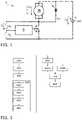
- figure 1 shows a circuit diagram of an electric drive A.
- the electric drive A has a voltage source Q in the form of an accumulator Q, which provides a voltage U q or an accumulator voltage U q at 24 V.
- There is an electric motor M to which a diode D1 is arranged in parallel, through which a diode current I D1 can flow .
- the electric motor M and the diode D 1 are connected in series with the accumulator Q together.
- the passive diode freewheeling shown here and described below is only to be understood as an example; the function can alternatively also be ensured by active freewheeling, for example by an appropriately controlled MOSFET.
- control unit S with a voltage divider, which is formed by a first ohmic resistor R1 and a second ohmic resistor R2.
- a first voltage U 1 which drops across the first ohmic resistor R1, can be detected via the voltage divider.
- the control unit S is designed as a microcontroller S. This closes the circuit to the accumulator Q.
- the electric drive A is used in a vacuum cleaner to drive the floor brush.
- Various advantages of the method according to the invention are to be considered in more detail on the basis of this exemplary embodiment.
- figure 2 shows a flow chart of a method according to the invention for operating the electric drive of FIG figure 1 .
- a first step 100 the electric motor M is operated by the control unit S at a predetermined speed using a pulse width modulated battery voltage U q with a predetermined duty cycle, see the diagram in FIG figure 3 left before a first measurement time T 1 .
- the accumulator voltage U q is recorded.
- the voltage U eff effectively present at the electric motor M is determined by multiplying the duty cycle by the accumulator voltage U q .
- a fourth step 400 the induced voltage U i of the electric motor M is determined. While immediately after If the battery voltage U q is still maintained by the diode current I D1 of the diode D 1 when the battery voltage U q is interrupted, the battery voltage U q is detected in a second partial step 420 at the first measurement time T 1 , see FIG figure 3 . When the diode current I D1 of the diode D 1 has decayed, a superimposed voltage U k of the electric motor M is detected in a third partial step 430 at a second measurement time T 2 , see also figure 3 .
- the pulse-width-modulated battery voltage U q can then be applied to the electric motor M again, so that the operation of the electric motor M can be resumed as before.
- the induced voltage U i of the electric motor M is determined in a fourth partial step 440 by subtracting the superimposed voltage U k of the electric motor M from the battery voltage U q , so that the induced voltage U i of the electric motor M is now available.
- a load indicator of the electric motor M is then determined by subtracting the induced voltage U i of the electric motor M from the voltage U eff effectively present at the electric motor M. Then, in a first sixth sub-step 600a, the torque and/or the current of the electric motor M is determined by multiplying the load indicator by a predetermined factor. In parallel, in a second, sixth partial step 600b, the speed of the electric motor M is determined by multiplying the induced voltage U i of the electric motor M by a predetermined factor.
- a seventh step 700 the load indicator and/or the torque and/or the current of the electric motor M is compared with at least one reference value and/or with at least one threshold value, which corresponds to a type of ground.
- the electric motor M is then operated by the control unit S as a function of the detected type of ground.
- the power of the floor brush can now be regulated.
- the presence or absence of the floor brush can also be detected.
- the speed of the electric motor M can be determined without sensors and used, for example, for speed control.
Landscapes
- Engineering & Computer Science (AREA)
- Mechanical Engineering (AREA)
- Electric Vacuum Cleaner (AREA)
- Nozzles For Electric Vacuum Cleaners (AREA)
Claims (11)
- Procédé permettant de faire fonctionner un entraînement (A) électrique d'une soufflante et/ou d'une brosse d'un aspirateur ou d'un robot aspirateur,dans lequel l'entraînement (A) électrique comporte une source de tension (Q), un moteur électrique (M) et une unité de commande (S),le procédé comportant au moins les étapes suivantes :le fonctionnement (100) du moteur électrique (M) côté unité de commande (S) à une vitesse de rotation prédéterminée au moyen d'une tension (Uq) modulée en largeur d'impulsion de la source de tension (Q) avec un rapport cyclique prédéterminé,la détection (200) de la tension (Uq) de la source de tension (Q),la détermination (300) de la tension (Ueff) appliquée de manière effective au moteur électrique (M) par multiplication du rapport cyclique par la tension (Uq) de la source de tension (Q),la détermination (400) de la tension (Ui) induite du moteur électrique (M), etla détermination (500) d'un indicateur de charge du moteur électrique (M) par soustraction de la tension (Ui) induite du moteur électrique (M) à la tension (Ueff) appliquée de manière effective au moteur électrique (M),dans lequel l'entraînement (A) électrique comporte également une roue libre (D1) laquelle est disposée parallèlement au moteur électrique (M),dans lequel la détermination (400) de la tension (Ui) induite du moteur électrique (M) comporte au moins les étapes suivantes :l'interruption (410) de la tension (Uq) modulée en largeur d'impulsion de la source de tension (Q) au niveau du moteur électrique (M),la détection (420), à un premier instant de mesure (T1) pendant lequel un courant (ID1) circule à travers la roue libre (D1), de la tension (Uq) de la source de tension (Q),la détection (430), à un second instant de mesure (T2) pendant lequel aucun courant (ID1) ne circule à travers la roue libre (D1), d'une tension (Uk) superposée du moteur électrique (M), etla détermination (440) de la tension (Ui) induite du moteur électrique (M) par soustraction de la tension (Uk) superposée du moteur électrique (M) à la tension (Uq) de la source de tension (Q),l'utilisation de l'indicateur de charge déterminé pour commander ou réguler la puissance du moteur électrique (M).
- Procédé selon la revendication 1, comportant au moins l'étape supplémentaire suivante :
la détermination (600a) du couple et/ou du courant du moteur électrique (M) par multiplication de l'indicateur de charge par un facteur prédéterminé. - Procédé selon la revendication 1, comportant au moins l'étape supplémentaire suivante :
la détermination (600b) de la vitesse de rotation du moteur électrique (M) par multiplication de la tension (Ui) induite du moteur électrique (M) par un facteur prédéterminé. - Procédé selon l'une quelconque des revendications précédentes, comportant au moins les étapes supplémentaires suivantes :la comparaison (700), dans le cas où le moteur électrique (M) est conçu pour entraîner une soufflante ou une brosse d'un aspirateur ou d'un robot aspirateur, de l'indicateur de charge et/ou du couple et/ou du courant du moteur électrique (M) avec au moins une valeur de référence et/ou avec au moins une valeur seuil correspondant à un type de sol, etle fonctionnement (800) du moteur électrique (M) côté unité de commande (S) en fonction du type de sol reconnu.
- Procédé selon la revendication 4, caractérisé en ce que
dans le cas où le moteur électrique (M) est conçu pour entraîner une brosse d'un aspirateur ou d'un robot aspirateur, une valeur de référence et/ou une valeur seuil est prédéterminée de telle sorte que la comparaison (700) permet de distinguer l'absence et la présence de la brosse. - Procédé selon la revendication 4 ou 5, caractérisé en ce que
le fonctionnement (800) du moteur électrique (M) côté unité de commande (S) s'effectue par régulation de la vitesse de rotation. - Procédé selon l'une quelconque des revendications précédentes, caractérisé en ce quela détermination (400) de la tension (Ui) induite du moteur électrique (M) et/oula détection (430) de la tension (Uk) superposée du moteur électrique (M) s'effectuent par l'intermédiaire d'un diviseur de tension (R1, R2) disposé en série avec le moteur électrique (M) et en parallèle avec l'unité de commande (S).
- Procédé selon l'une quelconque des revendications 3 à 7, caractérisé en ce que
la détection (430 ; 440) de la tension (Uq) de la source de tension (Q) au premier instant de mesure (T1) et/ou au second instant de mesure (T2) s'effectue par détection (430 ; 440) sur une période de mesure prédéterminée (T1 ; T2) suivie par formation de la valeur moyenne. - Procédé selon l'une quelconque des revendications précédentes, caractérisé en ce que
le moteur électrique (M) est un moteur électrique (M) d'une soufflante ou un moteur électrique (M) d'une brosse d'un aspirateur ou d'un robot aspirateur. - Unité de commande (S) permettant de faire fonctionner un entraînement (A) électrique, de préférence une soufflante et/ou une brosse d'un aspirateur ou d'un robot aspirateur, dans laquelle ladite unité de commande (S) est conçue pour exécuter un procédé selon l'une quelconque des revendications 1 à 9.
- Appareil électroménager, de préférence aspirateur et/ou robot aspirateur, de préférence fonctionnant sur accumulateur, comportantau moins un entraînement (A) électrique,au moins une source de tension (Q),au moins un moteur électrique (M) etau moins une unité de commande (S) selon la revendication 10.
Applications Claiming Priority (1)
| Application Number | Priority Date | Filing Date | Title |
|---|---|---|---|
| DE102017125956.2A DE102017125956A1 (de) | 2017-11-07 | 2017-11-07 | Verfahren zum Betrieb eines elektrischen Antriebs, vorzugsweise eines Gebläses und/oder einer Bürste eines Staubsaugers oder eines Staubsaugroboters |
Publications (2)
| Publication Number | Publication Date |
|---|---|
| EP3479745A1 EP3479745A1 (fr) | 2019-05-08 |
| EP3479745B1 true EP3479745B1 (fr) | 2022-10-26 |
Family
ID=63832271
Family Applications (1)
| Application Number | Title | Priority Date | Filing Date |
|---|---|---|---|
| EP18199498.9A Active EP3479745B1 (fr) | 2017-11-07 | 2018-10-10 | Procédé de fonctionnement d'un entraînement électrique, de préférence d'un ventilateur et / ou d'une brosse d'un aspirateur ou d'un aspirateur robot |
Country Status (4)
| Country | Link |
|---|---|
| EP (1) | EP3479745B1 (fr) |
| DE (1) | DE102017125956A1 (fr) |
| ES (1) | ES2929717T3 (fr) |
| PL (1) | PL3479745T3 (fr) |
Families Citing this family (6)
| Publication number | Priority date | Publication date | Assignee | Title |
|---|---|---|---|---|
| DE102019211014B4 (de) * | 2019-07-25 | 2024-07-18 | Vorwerk & Co. Interholding Gmbh | Haushaltsreinigungsgerät mit Akkuantrieb |
| CN113014151B (zh) * | 2019-12-18 | 2023-12-19 | 珠海格力电器股份有限公司 | 一种无刷直流电机控制方法、装置、无刷直流电机及电器 |
| CN112994533B (zh) * | 2019-12-18 | 2023-05-26 | 珠海格力电器股份有限公司 | 一种无刷直流电机控制方法、装置、无刷直流电机及电器 |
| EP4238470B1 (fr) * | 2022-03-04 | 2024-07-17 | Vorwerk & Co. Interholding GmbH | Dispositif de nettoyage du sol ciomprenant une commande d'une alimentation en liquide, ainsi que procédé |
| EP4238469B1 (fr) * | 2022-03-04 | 2024-07-31 | Vorwerk & Co. Interholding GmbH | Appareil de nettoyage à détection de l'état d'une surface et procédé |
| CN119024161A (zh) * | 2023-05-25 | 2024-11-26 | 北京小米移动软件有限公司 | 地刷类型识别方法和装置、清洁设备、存储介质 |
Family Cites Families (8)
| Publication number | Priority date | Publication date | Assignee | Title |
|---|---|---|---|---|
| EP0479609A3 (en) * | 1990-10-05 | 1993-01-20 | Hitachi, Ltd. | Vacuum cleaner and control method thereof |
| US5811946A (en) * | 1992-03-16 | 1998-09-22 | Lockheed Martin Corporation | System and method for velocity control of a D.C. Motor |
| GB2303719B (en) * | 1995-07-26 | 2000-01-26 | Black & Decker Inc | An energy management system for a cordless vegetation cutter |
| JP3658310B2 (ja) * | 2000-11-16 | 2005-06-08 | 東芝テック株式会社 | Pwm制御回路、電動送風機及び電気掃除機 |
| US6838847B2 (en) * | 2002-05-09 | 2005-01-04 | Siemens Vdo Automotive Inc. | Stall protection based on back EMF detection |
| US7106021B2 (en) * | 2004-05-04 | 2006-09-12 | International Business Machines Corporation | Method, system, and program product for feedback control of a target system utilizing imposition of a periodic modulating signal onto a command signal |
| US7205737B1 (en) * | 2006-01-04 | 2007-04-17 | Robert Bosch Gmbh | Systems and methods of monitoring a motor load |
| US9383414B2 (en) * | 2014-08-29 | 2016-07-05 | Atieva, Inc | Method of diagnosing a blocked heat exchanger |
-
2017
- 2017-11-07 DE DE102017125956.2A patent/DE102017125956A1/de not_active Withdrawn
-
2018
- 2018-10-10 EP EP18199498.9A patent/EP3479745B1/fr active Active
- 2018-10-10 ES ES18199498T patent/ES2929717T3/es active Active
- 2018-10-10 PL PL18199498.9T patent/PL3479745T3/pl unknown
Also Published As
| Publication number | Publication date |
|---|---|
| PL3479745T3 (pl) | 2023-01-30 |
| DE102017125956A1 (de) | 2019-05-09 |
| EP3479745A1 (fr) | 2019-05-08 |
| ES2929717T3 (es) | 2022-12-01 |
Similar Documents
| Publication | Publication Date | Title |
|---|---|---|
| EP3479745B1 (fr) | Procédé de fonctionnement d'un entraînement électrique, de préférence d'un ventilateur et / ou d'une brosse d'un aspirateur ou d'un aspirateur robot | |
| DE102009020842B4 (de) | System zum Steuern der Geschwindigkeit eines Elektromotors in einem Kraftfahrzeug | |
| EP3119260B1 (fr) | Méthode pour nettoyer un filtre d'un aspirateur et l'aspirateur | |
| EP3162266B1 (fr) | Appareil de nettoyage et procédé pour utiliser l'appareil de nettoyage | |
| DE102013101700A1 (de) | Reinigungssystem und Steuerverfahren dafür | |
| EP3430701B1 (fr) | Appareil ménager et procédé de fonctionnement d'un appareil ménager | |
| EP1527470A1 (fr) | Ensemble de commande pour entrainement electromagnetique | |
| DE102007021299A1 (de) | Verfahren und Vorrichtung zum Steuern der Drehzahl zumindest eines Elektromotors in einem mobilen Gerät, insbesondere in einer Saugbürstenvorrichtung oder einem Staubsammelroboter | |
| DE102012102631A1 (de) | Verfahren zum Einstellen eines Saugsystems, Verfahren zum Betreiben eines Saugsystems und Saugsystem | |
| EP2946711B1 (fr) | Procédé de fonctionnement d'un aspirateur et aspirateur | |
| EP1987584A2 (fr) | Mécanisme d'entraînement d'un dispositif de réglage permettant de régler une pièce de véhicule et procédé de fonctionnement de ce mécanisme d'entraînement | |
| EP3643215B1 (fr) | Procédé et dispositif de détection d'un type de brosse motorisée pour un aspirateur, procédé et dispositif de fonctionnement d'un aspirateur, brosse motorisée pour un aspirateur et aspirateur | |
| EP2672871B1 (fr) | Aspirateur et méthode pour nettoyer un filtre | |
| EP4029423B1 (fr) | Fonction d'apprentissage pour aspirateurs pourvus d'injecteurs moteur | |
| DE102016206917A1 (de) | Verfahren zur Leistungsanpassung eines akkumulatorbetriebenen Staubsaugers | |
| DE102011090069A1 (de) | Lüftersystem und Verfahren zur Steuerung eines Lüftermotors | |
| DE102007040484B4 (de) | Verfahren zur Regelung eines Haushaltsgeräts | |
| EP4593676A1 (fr) | Procédé et dispositif de commande pour faire fonctionner un appareil de nettoyage et appareil de nettoyage | |
| EP3617721B1 (fr) | Reconnaissance d'impédance d'un consommateur d'une station de charge | |
| EP4212082A1 (fr) | Aspirateur, de préférence aspirateur à main | |
| EP3790177B1 (fr) | Procédé de fonctionnement d'un appareil d'usinage électrique et appareil d'usinage électrique | |
| EP3821778A1 (fr) | Aspirateur et procédé de fonctionnement d'un aspirateur | |
| DE102006023966A1 (de) | Drehmomentsteuereinrichtung für elektrische Werkzeuge | |
| DE102019104429A1 (de) | Bodenpflegegerät und Verfahren zum Betrieb eines Bodenpflegegeräts | |
| DE102004041765A1 (de) | Schaltungsanordnung und Verfahren zum Betreiben eines Elektromotors mit veränderlicher Drehzahl an einer Gleichspannungsquelle |
Legal Events
| Date | Code | Title | Description |
|---|---|---|---|
| PUAI | Public reference made under article 153(3) epc to a published international application that has entered the european phase |
Free format text: ORIGINAL CODE: 0009012 |
|
| STAA | Information on the status of an ep patent application or granted ep patent |
Free format text: STATUS: THE APPLICATION HAS BEEN PUBLISHED |
|
| AK | Designated contracting states |
Kind code of ref document: A1 Designated state(s): AL AT BE BG CH CY CZ DE DK EE ES FI FR GB GR HR HU IE IS IT LI LT LU LV MC MK MT NL NO PL PT RO RS SE SI SK SM TR |
|
| AX | Request for extension of the european patent |
Extension state: BA ME |
|
| STAA | Information on the status of an ep patent application or granted ep patent |
Free format text: STATUS: REQUEST FOR EXAMINATION WAS MADE |
|
| 17P | Request for examination filed |
Effective date: 20191108 |
|
| RBV | Designated contracting states (corrected) |
Designated state(s): AL AT BE BG CH CY CZ DE DK EE ES FI FR GB GR HR HU IE IS IT LI LT LU LV MC MK MT NL NO PL PT RO RS SE SI SK SM TR |
|
| GRAP | Despatch of communication of intention to grant a patent |
Free format text: ORIGINAL CODE: EPIDOSNIGR1 |
|
| STAA | Information on the status of an ep patent application or granted ep patent |
Free format text: STATUS: GRANT OF PATENT IS INTENDED |
|
| INTG | Intention to grant announced |
Effective date: 20220623 |
|
| GRAS | Grant fee paid |
Free format text: ORIGINAL CODE: EPIDOSNIGR3 |
|
| GRAA | (expected) grant |
Free format text: ORIGINAL CODE: 0009210 |
|
| STAA | Information on the status of an ep patent application or granted ep patent |
Free format text: STATUS: THE PATENT HAS BEEN GRANTED |
|
| REG | Reference to a national code |
Ref country code: DE Ref legal event code: R084 Ref document number: 502018010903 Country of ref document: DE |
|
| AK | Designated contracting states |
Kind code of ref document: B1 Designated state(s): AL AT BE BG CH CY CZ DE DK EE ES FI FR GB GR HR HU IE IS IT LI LT LU LV MC MK MT NL NO PL PT RO RS SE SI SK SM TR |
|
| REG | Reference to a national code |
Ref country code: GB Ref legal event code: FG4D Free format text: NOT ENGLISH |
|
| REG | Reference to a national code |
Ref country code: CH Ref legal event code: EP |
|
| REG | Reference to a national code |
Ref country code: DE Ref legal event code: R096 Ref document number: 502018010903 Country of ref document: DE |
|
| REG | Reference to a national code |
Ref country code: AT Ref legal event code: REF Ref document number: 1526437 Country of ref document: AT Kind code of ref document: T Effective date: 20221115 |
|
| REG | Reference to a national code |
Ref country code: IE Ref legal event code: FG4D Free format text: LANGUAGE OF EP DOCUMENT: GERMAN |
|
| REG | Reference to a national code |
Ref country code: ES Ref legal event code: FG2A Ref document number: 2929717 Country of ref document: ES Kind code of ref document: T3 Effective date: 20221201 |
|
| REG | Reference to a national code |
Ref country code: ES Ref legal event code: GC2A Effective date: 20221201 |
|
| REG | Reference to a national code |
Ref country code: GB Ref legal event code: 746 Effective date: 20221129 |
|
| REG | Reference to a national code |
Ref country code: LT Ref legal event code: MG9D |
|
| REG | Reference to a national code |
Ref country code: NL Ref legal event code: MP Effective date: 20221026 |
|
| PG25 | Lapsed in a contracting state [announced via postgrant information from national office to epo] |
Ref country code: NL Free format text: LAPSE BECAUSE OF FAILURE TO SUBMIT A TRANSLATION OF THE DESCRIPTION OR TO PAY THE FEE WITHIN THE PRESCRIBED TIME-LIMIT Effective date: 20221026 |
|
| PG25 | Lapsed in a contracting state [announced via postgrant information from national office to epo] |
Ref country code: SE Free format text: LAPSE BECAUSE OF FAILURE TO SUBMIT A TRANSLATION OF THE DESCRIPTION OR TO PAY THE FEE WITHIN THE PRESCRIBED TIME-LIMIT Effective date: 20221026 Ref country code: PT Free format text: LAPSE BECAUSE OF FAILURE TO SUBMIT A TRANSLATION OF THE DESCRIPTION OR TO PAY THE FEE WITHIN THE PRESCRIBED TIME-LIMIT Effective date: 20230227 Ref country code: NO Free format text: LAPSE BECAUSE OF FAILURE TO SUBMIT A TRANSLATION OF THE DESCRIPTION OR TO PAY THE FEE WITHIN THE PRESCRIBED TIME-LIMIT Effective date: 20230126 Ref country code: LT Free format text: LAPSE BECAUSE OF FAILURE TO SUBMIT A TRANSLATION OF THE DESCRIPTION OR TO PAY THE FEE WITHIN THE PRESCRIBED TIME-LIMIT Effective date: 20221026 Ref country code: FI Free format text: LAPSE BECAUSE OF FAILURE TO SUBMIT A TRANSLATION OF THE DESCRIPTION OR TO PAY THE FEE WITHIN THE PRESCRIBED TIME-LIMIT Effective date: 20221026 |
|
| PG25 | Lapsed in a contracting state [announced via postgrant information from national office to epo] |
Ref country code: RS Free format text: LAPSE BECAUSE OF FAILURE TO SUBMIT A TRANSLATION OF THE DESCRIPTION OR TO PAY THE FEE WITHIN THE PRESCRIBED TIME-LIMIT Effective date: 20221026 Ref country code: LV Free format text: LAPSE BECAUSE OF FAILURE TO SUBMIT A TRANSLATION OF THE DESCRIPTION OR TO PAY THE FEE WITHIN THE PRESCRIBED TIME-LIMIT Effective date: 20221026 Ref country code: IS Free format text: LAPSE BECAUSE OF FAILURE TO SUBMIT A TRANSLATION OF THE DESCRIPTION OR TO PAY THE FEE WITHIN THE PRESCRIBED TIME-LIMIT Effective date: 20230226 Ref country code: HR Free format text: LAPSE BECAUSE OF FAILURE TO SUBMIT A TRANSLATION OF THE DESCRIPTION OR TO PAY THE FEE WITHIN THE PRESCRIBED TIME-LIMIT Effective date: 20221026 Ref country code: GR Free format text: LAPSE BECAUSE OF FAILURE TO SUBMIT A TRANSLATION OF THE DESCRIPTION OR TO PAY THE FEE WITHIN THE PRESCRIBED TIME-LIMIT Effective date: 20230127 |
|
| P01 | Opt-out of the competence of the unified patent court (upc) registered |
Effective date: 20230528 |
|
| REG | Reference to a national code |
Ref country code: DE Ref legal event code: R097 Ref document number: 502018010903 Country of ref document: DE |
|
| PG25 | Lapsed in a contracting state [announced via postgrant information from national office to epo] |
Ref country code: SM Free format text: LAPSE BECAUSE OF FAILURE TO SUBMIT A TRANSLATION OF THE DESCRIPTION OR TO PAY THE FEE WITHIN THE PRESCRIBED TIME-LIMIT Effective date: 20221026 Ref country code: RO Free format text: LAPSE BECAUSE OF FAILURE TO SUBMIT A TRANSLATION OF THE DESCRIPTION OR TO PAY THE FEE WITHIN THE PRESCRIBED TIME-LIMIT Effective date: 20221026 Ref country code: EE Free format text: LAPSE BECAUSE OF FAILURE TO SUBMIT A TRANSLATION OF THE DESCRIPTION OR TO PAY THE FEE WITHIN THE PRESCRIBED TIME-LIMIT Effective date: 20221026 Ref country code: DK Free format text: LAPSE BECAUSE OF FAILURE TO SUBMIT A TRANSLATION OF THE DESCRIPTION OR TO PAY THE FEE WITHIN THE PRESCRIBED TIME-LIMIT Effective date: 20221026 Ref country code: CZ Free format text: LAPSE BECAUSE OF FAILURE TO SUBMIT A TRANSLATION OF THE DESCRIPTION OR TO PAY THE FEE WITHIN THE PRESCRIBED TIME-LIMIT Effective date: 20221026 |
|
| PG25 | Lapsed in a contracting state [announced via postgrant information from national office to epo] |
Ref country code: SK Free format text: LAPSE BECAUSE OF FAILURE TO SUBMIT A TRANSLATION OF THE DESCRIPTION OR TO PAY THE FEE WITHIN THE PRESCRIBED TIME-LIMIT Effective date: 20221026 Ref country code: AL Free format text: LAPSE BECAUSE OF FAILURE TO SUBMIT A TRANSLATION OF THE DESCRIPTION OR TO PAY THE FEE WITHIN THE PRESCRIBED TIME-LIMIT Effective date: 20221026 |
|
| PLBE | No opposition filed within time limit |
Free format text: ORIGINAL CODE: 0009261 |
|
| STAA | Information on the status of an ep patent application or granted ep patent |
Free format text: STATUS: NO OPPOSITION FILED WITHIN TIME LIMIT |
|
| 26N | No opposition filed |
Effective date: 20230727 |
|
| PG25 | Lapsed in a contracting state [announced via postgrant information from national office to epo] |
Ref country code: SI Free format text: LAPSE BECAUSE OF FAILURE TO SUBMIT A TRANSLATION OF THE DESCRIPTION OR TO PAY THE FEE WITHIN THE PRESCRIBED TIME-LIMIT Effective date: 20221026 |
|
| PG25 | Lapsed in a contracting state [announced via postgrant information from national office to epo] |
Ref country code: MC Free format text: LAPSE BECAUSE OF FAILURE TO SUBMIT A TRANSLATION OF THE DESCRIPTION OR TO PAY THE FEE WITHIN THE PRESCRIBED TIME-LIMIT Effective date: 20221026 |
|
| REG | Reference to a national code |
Ref country code: CH Ref legal event code: PL |
|
| REG | Reference to a national code |
Ref country code: BE Ref legal event code: MM Effective date: 20231031 |
|
| PG25 | Lapsed in a contracting state [announced via postgrant information from national office to epo] |
Ref country code: LU Free format text: LAPSE BECAUSE OF NON-PAYMENT OF DUE FEES Effective date: 20231010 |
|
| PG25 | Lapsed in a contracting state [announced via postgrant information from national office to epo] |
Ref country code: LU Free format text: LAPSE BECAUSE OF NON-PAYMENT OF DUE FEES Effective date: 20231010 |
|
| PG25 | Lapsed in a contracting state [announced via postgrant information from national office to epo] |
Ref country code: CH Free format text: LAPSE BECAUSE OF NON-PAYMENT OF DUE FEES Effective date: 20231031 |
|
| PG25 | Lapsed in a contracting state [announced via postgrant information from national office to epo] |
Ref country code: CH Free format text: LAPSE BECAUSE OF NON-PAYMENT OF DUE FEES Effective date: 20231031 |
|
| PG25 | Lapsed in a contracting state [announced via postgrant information from national office to epo] |
Ref country code: BE Free format text: LAPSE BECAUSE OF NON-PAYMENT OF DUE FEES Effective date: 20231031 |
|
| PG25 | Lapsed in a contracting state [announced via postgrant information from national office to epo] |
Ref country code: IE Free format text: LAPSE BECAUSE OF NON-PAYMENT OF DUE FEES Effective date: 20231010 |
|
| PG25 | Lapsed in a contracting state [announced via postgrant information from national office to epo] |
Ref country code: IE Free format text: LAPSE BECAUSE OF NON-PAYMENT OF DUE FEES Effective date: 20231010 |
|
| PG25 | Lapsed in a contracting state [announced via postgrant information from national office to epo] |
Ref country code: BG Free format text: LAPSE BECAUSE OF FAILURE TO SUBMIT A TRANSLATION OF THE DESCRIPTION OR TO PAY THE FEE WITHIN THE PRESCRIBED TIME-LIMIT Effective date: 20221026 |
|
| PG25 | Lapsed in a contracting state [announced via postgrant information from national office to epo] |
Ref country code: BG Free format text: LAPSE BECAUSE OF FAILURE TO SUBMIT A TRANSLATION OF THE DESCRIPTION OR TO PAY THE FEE WITHIN THE PRESCRIBED TIME-LIMIT Effective date: 20221026 |
|
| REG | Reference to a national code |
Ref country code: AT Ref legal event code: MM01 Ref document number: 1526437 Country of ref document: AT Kind code of ref document: T Effective date: 20231010 |
|
| PG25 | Lapsed in a contracting state [announced via postgrant information from national office to epo] |
Ref country code: AT Free format text: LAPSE BECAUSE OF NON-PAYMENT OF DUE FEES Effective date: 20231010 |
|
| PG25 | Lapsed in a contracting state [announced via postgrant information from national office to epo] |
Ref country code: AT Free format text: LAPSE BECAUSE OF NON-PAYMENT OF DUE FEES Effective date: 20231010 |
|
| PG25 | Lapsed in a contracting state [announced via postgrant information from national office to epo] |
Ref country code: CY Free format text: LAPSE BECAUSE OF FAILURE TO SUBMIT A TRANSLATION OF THE DESCRIPTION OR TO PAY THE FEE WITHIN THE PRESCRIBED TIME-LIMIT; INVALID AB INITIO Effective date: 20181010 |
|
| PG25 | Lapsed in a contracting state [announced via postgrant information from national office to epo] |
Ref country code: HU Free format text: LAPSE BECAUSE OF FAILURE TO SUBMIT A TRANSLATION OF THE DESCRIPTION OR TO PAY THE FEE WITHIN THE PRESCRIBED TIME-LIMIT; INVALID AB INITIO Effective date: 20181010 |
|
| PGFP | Annual fee paid to national office [announced via postgrant information from national office to epo] |
Ref country code: PL Payment date: 20250930 Year of fee payment: 8 Ref country code: TR Payment date: 20250929 Year of fee payment: 8 |
|
| PGFP | Annual fee paid to national office [announced via postgrant information from national office to epo] |
Ref country code: DE Payment date: 20251031 Year of fee payment: 8 |
|
| PGFP | Annual fee paid to national office [announced via postgrant information from national office to epo] |
Ref country code: GB Payment date: 20251023 Year of fee payment: 8 |
|
| PGFP | Annual fee paid to national office [announced via postgrant information from national office to epo] |
Ref country code: IT Payment date: 20251022 Year of fee payment: 8 |
|
| PGFP | Annual fee paid to national office [announced via postgrant information from national office to epo] |
Ref country code: FR Payment date: 20251027 Year of fee payment: 8 |
|
| PGFP | Annual fee paid to national office [announced via postgrant information from national office to epo] |
Ref country code: ES Payment date: 20251118 Year of fee payment: 8 |