EP3480042B1 - Fahrzeugtür und verfahren zur herstellung einer kraftfahrzeugtür - Google Patents
Fahrzeugtür und verfahren zur herstellung einer kraftfahrzeugtür Download PDFInfo
- Publication number
- EP3480042B1 EP3480042B1 EP18204654.0A EP18204654A EP3480042B1 EP 3480042 B1 EP3480042 B1 EP 3480042B1 EP 18204654 A EP18204654 A EP 18204654A EP 3480042 B1 EP3480042 B1 EP 3480042B1
- Authority
- EP
- European Patent Office
- Prior art keywords
- panel
- adhesive
- ribs
- coating
- vehicle door
- Prior art date
- Legal status (The legal status is an assumption and is not a legal conclusion. Google has not performed a legal analysis and makes no representation as to the accuracy of the status listed.)
- Active
Links
- 238000000034 method Methods 0.000 title claims description 12
- 238000004519 manufacturing process Methods 0.000 title claims description 11
- 239000000853 adhesive Substances 0.000 claims description 100
- 230000001070 adhesive effect Effects 0.000 claims description 100
- 239000011248 coating agent Substances 0.000 claims description 58
- 238000000576 coating method Methods 0.000 claims description 58
- XLYOFNOQVPJJNP-UHFFFAOYSA-N water Substances O XLYOFNOQVPJJNP-UHFFFAOYSA-N 0.000 claims description 58
- 230000002093 peripheral effect Effects 0.000 claims description 47
- 238000007689 inspection Methods 0.000 claims description 7
- 230000000052 comparative effect Effects 0.000 description 7
- 238000012986 modification Methods 0.000 description 2
- 230000004048 modification Effects 0.000 description 2
- 238000007789 sealing Methods 0.000 description 2
- 238000007599 discharging Methods 0.000 description 1
- 230000000694 effects Effects 0.000 description 1
- 239000005357 flat glass Substances 0.000 description 1
Images



Classifications
-
- B—PERFORMING OPERATIONS; TRANSPORTING
- B60—VEHICLES IN GENERAL
- B60J—WINDOWS, WINDSCREENS, NON-FIXED ROOFS, DOORS, OR SIMILAR DEVICES FOR VEHICLES; REMOVABLE EXTERNAL PROTECTIVE COVERINGS SPECIALLY ADAPTED FOR VEHICLES
- B60J5/00—Doors
- B60J5/10—Doors arranged at the vehicle rear
- B60J5/101—Doors arranged at the vehicle rear for non-load transporting vehicles, i.e. family cars including vans
- B60J5/107—Doors arranged at the vehicle rear for non-load transporting vehicles, i.e. family cars including vans constructional details, e.g. about door frame, panels, materials used, reinforcements
-
- B—PERFORMING OPERATIONS; TRANSPORTING
- B60—VEHICLES IN GENERAL
- B60J—WINDOWS, WINDSCREENS, NON-FIXED ROOFS, DOORS, OR SIMILAR DEVICES FOR VEHICLES; REMOVABLE EXTERNAL PROTECTIVE COVERINGS SPECIALLY ADAPTED FOR VEHICLES
- B60J5/00—Doors
- B60J5/10—Doors arranged at the vehicle rear
- B60J5/101—Doors arranged at the vehicle rear for non-load transporting vehicles, i.e. family cars including vans
-
- B—PERFORMING OPERATIONS; TRANSPORTING
- B29—WORKING OF PLASTICS; WORKING OF SUBSTANCES IN A PLASTIC STATE IN GENERAL
- B29C—SHAPING OR JOINING OF PLASTICS; SHAPING OF MATERIAL IN A PLASTIC STATE, NOT OTHERWISE PROVIDED FOR; AFTER-TREATMENT OF THE SHAPED PRODUCTS, e.g. REPAIRING
- B29C65/00—Joining or sealing of preformed parts, e.g. welding of plastics materials; Apparatus therefor
- B29C65/48—Joining or sealing of preformed parts, e.g. welding of plastics materials; Apparatus therefor using adhesives, i.e. using supplementary joining material; solvent bonding
-
- B—PERFORMING OPERATIONS; TRANSPORTING
- B29—WORKING OF PLASTICS; WORKING OF SUBSTANCES IN A PLASTIC STATE IN GENERAL
- B29C—SHAPING OR JOINING OF PLASTICS; SHAPING OF MATERIAL IN A PLASTIC STATE, NOT OTHERWISE PROVIDED FOR; AFTER-TREATMENT OF THE SHAPED PRODUCTS, e.g. REPAIRING
- B29C65/00—Joining or sealing of preformed parts, e.g. welding of plastics materials; Apparatus therefor
- B29C65/78—Means for handling the parts to be joined, e.g. for making containers or hollow articles, e.g. means for handling sheets, plates, web-like materials, tubular articles, hollow articles or elements to be joined therewith; Means for discharging the joined articles from the joining apparatus
- B29C65/7802—Positioning the parts to be joined, e.g. aligning, indexing or centring
- B29C65/782—Positioning the parts to be joined, e.g. aligning, indexing or centring by setting the gap between the parts to be joined
- B29C65/7823—Positioning the parts to be joined, e.g. aligning, indexing or centring by setting the gap between the parts to be joined by using distance pieces, i.e. by using spacers positioned between the parts to be joined and forming a part of the joint
- B29C65/7829—Positioning the parts to be joined, e.g. aligning, indexing or centring by setting the gap between the parts to be joined by using distance pieces, i.e. by using spacers positioned between the parts to be joined and forming a part of the joint said distance pieces being integral with at least one of the parts to be joined
-
- B—PERFORMING OPERATIONS; TRANSPORTING
- B29—WORKING OF PLASTICS; WORKING OF SUBSTANCES IN A PLASTIC STATE IN GENERAL
- B29C—SHAPING OR JOINING OF PLASTICS; SHAPING OF MATERIAL IN A PLASTIC STATE, NOT OTHERWISE PROVIDED FOR; AFTER-TREATMENT OF THE SHAPED PRODUCTS, e.g. REPAIRING
- B29C65/00—Joining or sealing of preformed parts, e.g. welding of plastics materials; Apparatus therefor
- B29C65/82—Testing the joint
- B29C65/8207—Testing the joint by mechanical methods
- B29C65/8246—Pressure tests, e.g. hydrostatic pressure tests
-
- B—PERFORMING OPERATIONS; TRANSPORTING
- B29—WORKING OF PLASTICS; WORKING OF SUBSTANCES IN A PLASTIC STATE IN GENERAL
- B29C—SHAPING OR JOINING OF PLASTICS; SHAPING OF MATERIAL IN A PLASTIC STATE, NOT OTHERWISE PROVIDED FOR; AFTER-TREATMENT OF THE SHAPED PRODUCTS, e.g. REPAIRING
- B29C66/00—General aspects of processes or apparatus for joining preformed parts
- B29C66/01—General aspects dealing with the joint area or with the area to be joined
- B29C66/05—Particular design of joint configurations
- B29C66/10—Particular design of joint configurations particular design of the joint cross-sections
- B29C66/11—Joint cross-sections comprising a single joint-segment, i.e. one of the parts to be joined comprising a single joint-segment in the joint cross-section
- B29C66/112—Single lapped joints
-
- B—PERFORMING OPERATIONS; TRANSPORTING
- B29—WORKING OF PLASTICS; WORKING OF SUBSTANCES IN A PLASTIC STATE IN GENERAL
- B29C—SHAPING OR JOINING OF PLASTICS; SHAPING OF MATERIAL IN A PLASTIC STATE, NOT OTHERWISE PROVIDED FOR; AFTER-TREATMENT OF THE SHAPED PRODUCTS, e.g. REPAIRING
- B29C66/00—General aspects of processes or apparatus for joining preformed parts
- B29C66/01—General aspects dealing with the joint area or with the area to be joined
- B29C66/05—Particular design of joint configurations
- B29C66/10—Particular design of joint configurations particular design of the joint cross-sections
- B29C66/13—Single flanged joints; Fin-type joints; Single hem joints; Edge joints; Interpenetrating fingered joints; Other specific particular designs of joint cross-sections not provided for in groups B29C66/11 - B29C66/12
- B29C66/131—Single flanged joints, i.e. one of the parts to be joined being rigid and flanged in the joint area
-
- B—PERFORMING OPERATIONS; TRANSPORTING
- B29—WORKING OF PLASTICS; WORKING OF SUBSTANCES IN A PLASTIC STATE IN GENERAL
- B29C—SHAPING OR JOINING OF PLASTICS; SHAPING OF MATERIAL IN A PLASTIC STATE, NOT OTHERWISE PROVIDED FOR; AFTER-TREATMENT OF THE SHAPED PRODUCTS, e.g. REPAIRING
- B29C66/00—General aspects of processes or apparatus for joining preformed parts
- B29C66/50—General aspects of joining tubular articles; General aspects of joining long products, i.e. bars or profiled elements; General aspects of joining single elements to tubular articles, hollow articles or bars; General aspects of joining several hollow-preforms to form hollow or tubular articles
- B29C66/51—Joining tubular articles, profiled elements or bars; Joining single elements to tubular articles, hollow articles or bars; Joining several hollow-preforms to form hollow or tubular articles
- B29C66/54—Joining several hollow-preforms, e.g. half-shells, to form hollow articles, e.g. for making balls, containers; Joining several hollow-preforms, e.g. half-cylinders, to form tubular articles
- B29C66/543—Joining several hollow-preforms, e.g. half-shells, to form hollow articles, e.g. for making balls, containers; Joining several hollow-preforms, e.g. half-cylinders, to form tubular articles joining more than two hollow-preforms to form said hollow articles
-
- B—PERFORMING OPERATIONS; TRANSPORTING
- B29—WORKING OF PLASTICS; WORKING OF SUBSTANCES IN A PLASTIC STATE IN GENERAL
- B29L—INDEXING SCHEME ASSOCIATED WITH SUBCLASS B29C, RELATING TO PARTICULAR ARTICLES
- B29L2031/00—Other particular articles
- B29L2031/30—Vehicles, e.g. ships or aircraft, or body parts thereof
-
- B—PERFORMING OPERATIONS; TRANSPORTING
- B29—WORKING OF PLASTICS; WORKING OF SUBSTANCES IN A PLASTIC STATE IN GENERAL
- B29L—INDEXING SCHEME ASSOCIATED WITH SUBCLASS B29C, RELATING TO PARTICULAR ARTICLES
- B29L2031/00—Other particular articles
- B29L2031/724—Doors
-
- B—PERFORMING OPERATIONS; TRANSPORTING
- B60—VEHICLES IN GENERAL
- B60J—WINDOWS, WINDSCREENS, NON-FIXED ROOFS, DOORS, OR SIMILAR DEVICES FOR VEHICLES; REMOVABLE EXTERNAL PROTECTIVE COVERINGS SPECIALLY ADAPTED FOR VEHICLES
- B60J5/00—Doors
- B60J5/04—Doors arranged at the vehicle sides
- B60J5/048—Doors arranged at the vehicle sides characterised by the material
- B60J5/0481—Doors arranged at the vehicle sides characterised by the material plastic
-
- F—MECHANICAL ENGINEERING; LIGHTING; HEATING; WEAPONS; BLASTING
- F16—ENGINEERING ELEMENTS AND UNITS; GENERAL MEASURES FOR PRODUCING AND MAINTAINING EFFECTIVE FUNCTIONING OF MACHINES OR INSTALLATIONS; THERMAL INSULATION IN GENERAL
- F16B—DEVICES FOR FASTENING OR SECURING CONSTRUCTIONAL ELEMENTS OR MACHINE PARTS TOGETHER, e.g. NAILS, BOLTS, CIRCLIPS, CLAMPS, CLIPS OR WEDGES; JOINTS OR JOINTING
- F16B11/00—Connecting constructional elements or machine parts by sticking or pressing them together, e.g. cold pressure welding
- F16B11/006—Connecting constructional elements or machine parts by sticking or pressing them together, e.g. cold pressure welding by gluing
Definitions
- Japanese Unexamined Patent Publication No. 2016-078566A discloses as a conventional vehicle door a door comprised of a plastic inner panel and outer panel bonded by an adhesive.
- JP2014-184885 discloses an inner and outer panel of a vehicle bonnet bonded by an adhesive.
- Any occurrence of water leakage can be confirmed by a water leakage test. Further, if water leakage occurs, the location of water leakage (location where adhesive partially is not coated) is identified and the water leakage is repaired by manual work of a repair worker.
- the present disclosure was made focusing on such a problem and has as its object to clarify the range of repair in the case where a water leakage occurs.
- the vehicle door is provided with a first panel and a second panel bonded to a panel bonding part of the first panel.
- the first panel is configured so as to be provided with a plurality of ribs, sticking out from the panel bonding part so as to cross the adhesive coated on the first panel or the second panel, along the coating direction of the adhesive.
- Each rib is provided with a non-visible part which is bonded to the second panel and which is covered by the second panel and can no longer be viewed from the outside and a visible part which extends from the non-visible part in a direction crossing the adhesive and which is not covered by the second panel and can be viewed from the outside.
- the method of production of a vehicle door comprises a coating step of coating a panel bonding part of a first panel with an adhesive so as to cross a plurality of ribs formed at the panel bonding part or coating an adhesive on a facing surface of a second panel facing the panel bonding part of the first panel on which the plurality of ribs are formed, a bonding step of bonding the second panel to the panel bonding part so that parts of the ribs not crossing the adhesive after the coating step can be viewed from the outside when coating the panel bonding part with the adhesive in the coating step and of bonding the second panel to the panel bonding part so that the adhesive crosses the ribs and so that parts of the ribs not crossing the adhesive can be viewed from the outside after the coating step when coating the facing surface of the second panel with the adhesive in the coating step, an inspection step of inspecting for any water leakage from a clearance between the first panel and the second panel divided into a plurality of regions along the coating direction of the adhesive by the ribs
- FIG. 1 is a front view of a vehicle door 100 according to one embodiment of the present disclosure.
- a vehicle door 100 according to the present embodiment is a liftgate type back door attached to the body of a vehicle at its rear side and opening and closing up and down in the vehicle height direction about the vehicle width direction as the axial direction.
- FIG. 2 is a disassembled perspective view of a vehicle door 100.
- the vehicle door 100 is provided with an inner panel 1 and outer panels 2.
- FIG. 2 illustrates five outer panels 2. In explaining the main parts of the disclosure, these do not have to be particularly differentiated, so below for convenience in explanation, the outer panels 2 will not be particularly differentiated in the explanation.
- the inner panel 1 is a plastic panel positioned at the inside of a vehicle compartment when the vehicle door 100 is attached to the vehicle.
- the inner panel 1 is formed with a rectangular shaped window-use opening 3 at a part at the top part of the panel extending in the vehicle front-back direction when the vehicle door 100 is attached to the vehicle.
- the outer panels 2 are plastic panels positioned at the outside of the vehicle compartment when the vehicle door 100 is attached to the vehicle.
- the outer panels 2 are bonded by an adhesive to a peripheral edge part 11 of the window-use opening 3 formed in the inner panel 1.
- a rear window glass (not shown) for covering the window-use opening 3 is bonded by an adhesive to the outer panels 2.
- FIG. 11 is a view showing simplified a peripheral edge part 211 of an inner panel 201 of a vehicle door 200 according to a comparative example different from the present embodiment and shows the part corresponding to the part surrounded by the broken line in FIG. 2 .
- FIG. 12 is a cross-sectional view of the vehicle door 200 according to the comparative example along the line XII-XII of FIG. 11 in the state when bonding an outer panel 202.
- FIG. 13 is a cross-sectional view of the vehicle door 200 according to the comparative example along line XIII-XIII of FIG. 11 in the state when bonding the outer panel 202.
- the peripheral edge part 211 of the inner panel 201 is coated with the adhesive along the peripheral direction of the peripheral edge part 211 or the facing surface of the outer panel 202 facing the peripheral edge part 11 is coated with the adhesive.
- the adhesive is coated for example by discharging from a nozzle the adhesive pumped in through piping.
- the adhesive performs the role as a seal for sealing the clearance formed between the inner panel 201 and the outer panel 202 after curing (below, referred to as the "clearance between panels") and preventing water from entering from the clearance between panels to the vehicle compartment. For this reason, if an uncoated location ends up being formed, as shown in FIG. 13 , it ends up becoming no longer possible to seal the clearance between panels by the adhesive, the seal becomes insufficient, and water leakage to the inside of the vehicle compartment is liable to occur.
- any occurrence of water leakage can be confirmed by a water leakage test. Further, if water leakage has occurred, the practice is to identify the water leakage location, that is, the uncoated location, and repair the water leakage by manual work of a repair worker.
- the clearance between panels is divided into a plurality of regions so that the range of repair when water leakage occurs becomes clear.
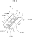
- FIG. 3 is a view showing simplified the peripheral edge part 11 of the inner panel 1 of the vehicle door 100 according to the present embodiment and partially shows the part surrounded by broken lines in FIG. 2 .
- the peripheral edge part 11 of the inner panel 1 of the vehicle door 100 is formed with a flange 12 and ribs 13.
- the flange 12 is a wall-shaped portion sticking out from the surface of the peripheral edge part 11 so as to extend substantially in parallel to the coating direction of the adhesive along the outer edge of the peripheral edge part 11.
- the ribs 13 are portions which stick out in line shapes from the surface of the peripheral edge part 11 so that parts (non-visible parts 131 explained later) cross the adhesive coated on the surface of the peripheral edge part 11, or the facing surface of the outer panel 2 facing the peripheral edge part 11. A plurality are formed at constant intervals in the coating direction. In the present embodiment, the ribs 13 are formed so as to extend in line shapes in a direction perpendicular to the coating direction of the adhesive.
- the ribs 13 extend up to the outer edge side of the peripheral edge part 11 so that a repair worker can view the parts not crossing the adhesive (visible parts 132 explained later) from the outside even after bonding the outer panel 2 and are formed so that in the present embodiment, the end parts at the outer edge side abut against the flange 12.
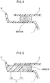
- FIG. 4 is a cross-sectional view of the vehicle door 100 according to the present embodiment along the line IV-IV of FIG. 3 in the state with an outer panel 2 bonded.
- FIG. 5 is a cross-sectional view of the vehicle door 100 according to the present embodiment along the line V-V of FIG. 3 in the state with the outer panel 2 bonded.
- the clearance between the peripheral edge part 11 of the inner panel 1 and the outer panel 2 is sealed by an adhesive.
- the clearance between the rib 13 and the outer panel 2 is sealed by an adhesive.
- the ribs 13 of the present embodiment are provided with non-visible parts 131 which are bonded to the outer panel 2 and covered by the outer panel 2 to no longer be visible from the outside and visible parts 132 which extend from the non-visible parts 131 in a direction crossing the adhesive (in the present embodiment, the direction perpendicular to the coating direction of the adhesive) and are not covered by the outer panel 2 so can be viewed from the outside.
- the visible parts 132 of the ribs 13 are formed so as to extend continuously from the non-visible parts 131 in a direction crossing the adhesive, but may also be formed to extend discontinuously.
- the non-visible parts 131 of the ribs 13 are bonded with the outer panel 2, so water entering into a certain region of the clearance between panels divided by the ribs 13 can be prevented from entering a region adjoining that region by the ribs 13. For this reason, it is possible to easily repair water leakage by recoating a repair-use adhesion along the entrance to the clearance between panels from the visible part 132 of one rib 13 between adjoining ribs 13 defining the region in which water leakage is confirmed to the visible part 132 of the other rib 13.
- the flange 12 is formed so as to extend along the outer edge of the peripheral edge part 11 substantially in parallel to the coating direction of the adhesive, so the flange 12 can be used to keep the repair-use and other adhesive from flowing to the outer edge side of the peripheral edge part 11 and to define the width of coating of the adhesive (length in direction perpendicular to coating direction).
- FIG. 9 is a flow chart for explaining the method of production of the vehicle door 100 according to the present embodiment.
- the peripheral edge part 11 is coated with an adhesive so as to cross parts of the ribs 13 formed at the peripheral edge part 11 of the window-use opening 3 of the inner panel 1 (non-visible parts 131).
- the adhesive is coated at the facing surface of the outer panel 2 forming the part facing the peripheral edge part 11 at which the ribs 13 are formed.
- step S2 when the peripheral edge part 11 of the inner panel 1 is coated with the adhesive at step S1, the peripheral edge part 11 is bonded with the outer panel 2 so that the parts of the ribs 13 not crossing the adhesive (visible parts 132) can be seen from the outside.
- the outer panel 2 when the facing surface of the outer panel 2 is coated with the adhesive at step S1, the outer panel 2 is bonded with the peripheral edge part 11 so that the adhesive crosses the ribs 13 and parts of the ribs 13 (visible parts 132) can be viewed from the outside.
- step S4 the region where water leakage is confirmed in the plurality of regions of the clearance between panels divided by the ribs 13 is repaired. Specifically, water leakage is repaired by recoating a repair-use adhesive along the entrance to the clearance between panels from the visible part 132 of the one rib 13 of adjoining ribs 13 defining the region where water leakage is confirmed to the visible part 132 of the other rib 13.
- the above explained vehicle door 100 is provided with an inner panel 1 (first panel) and an outer panel 2 (second panel) bonded to the peripheral edge part 11 of the inner panel 1 (panel bonding part).
- the inner panel 1 is configured provided with a plurality of ribs 13 sticking out from the peripheral edge part 11 along the coating direction of the adhesive so as to cross the adhesive coated on the inner panel 1 or the outer panel 2.
- each rib 13 is provided with a non-visible part 131 which is bonded to the outer panel 2 and which is covered by the outer panel 2 and can no longer be viewed from the outside and a visible part 132 which extends from the non-visible part 131 in a direction crossing the adhesive and which is not covered by the outer panel 2 and can be viewed from the outside.
- the repair worker can easily repair water leakage, so the number of steps of repair work can be reduced. Further, by clarifying the range of repair, the amount of use of the repair adhesive in the case where water leakage occurs can be kept to the minimum necessary extent, so the costs can be cut.
- the inner panel 1 (first panel) of the vehicle door 100 is configured further provided with a wall shaped flange 12 sticking out from the peripheral edge part 11 (panel bonding part) so as to extend in parallel with the coating direction of the adhesive.
- the ribs 13 are configured so that the edge parts at the visible part 132 sides abut against the flange 12.
- the flange 12 can be used to keep the repair-use and other adhesive from flowing to the outer edge side of the peripheral edge part and to define the coated width of the adhesive (length in direction perpendicular to coating direction). For this reason, it is possible to clarify more the range of repair.
- the visible parts 132 of the ribs 13 are formed more to the outer edge side of the peripheral edge part 11 than the non-visible parts 131. That is, the visible parts 132 of the ribs 13 are formed at the outer edge side of the vehicle door 100, so in the repair work, the visible parts 132 of the ribs 13 can be easily seen and repair can be easily performed and the work efficiency of repair work can be improved.
- the method of production of the vehicle door 100 comprises a coating step of coating a peripheral edge part 11 (panel bonding part) of an inner panel 1 (first panel) with an adhesive so as to cross a plurality of ribs 13 formed at the peripheral edge part 11 or coating an adhesive on a facing surface of an outer panel 2 (second panel) facing the peripheral edge part 11 of the inner panel 1 on which the plurality of ribs 13 are formed, a bonding step of bonding the outer panel 2 to the peripheral edge part 11 so that parts of the ribs 13 not crossing the adhesive can be viewed from the outside after the coating step when coating the peripheral edge part 11 with the adhesive in the coating step and of bonding the outer panel 2 to the peripheral edge part 11 so that the adhesive crosses the ribs 13 and so that parts of the ribs 13 not crossing the adhesive can be viewed from the outside after the coating step when coating the facing surface of the outer panel 2 with the adhesive in the coating step, an inspection step of inspecting for any water leakage from the clearance between the inner panel 1 and the outer panel
- the inner panel 1 was formed with the flange 12 and ribs 13.
- the flange 12 and ribs 13 at the outer panel 2 and bond the outer panel 2 to the inner panel 1.
- the first panel is the outer panel 2 and the second panel is the inner panel 1.
Landscapes
- Engineering & Computer Science (AREA)
- Mechanical Engineering (AREA)
- Automobile Manufacture Line, Endless Track Vehicle, Trailer (AREA)
Claims (5)
- Fahrzeugtür, umfassend:eine erste Verkleidung (1) undeine zweite Verkleidung, die mit einem Verkleidungsbindungsteil (11) der ersten Verkleidung (1) verbunden ist,wobei bei der Fahrzeugtürdie erste Verkleidung (1) mit mehreren Rippen (13) versehen ist, die aus dem Verkleidungsbindungsteil (11) derart herausragen, dass sie einen Klebstoff, mit dem die erste Verkleidung (1) oder die zweite Verkleidung (2) beschichtet ist, entlang der Beschichtungsrichtung des Klebstoffs durchziehen, undjede Rippe (13) versehen ist mit:
einem nicht sichtbaren Teil (131), der mit der zweiten Verkleidung (2) verbunden ist und der von der zweiten Verkleidung (2) bedeckt ist und von außen nicht mehr gesehen werden kann, und dadurch gekennzeichnet, dass jede Rippe (13) auch mit einem sichtbaren Teil (132) versehen ist, der sich von dem nicht sichtbaren Teil (131) in einer Richtung erstreckt, die den Klebstoff durchzieht, und der nicht von der zweiten Verkleidung (2) bedeckt ist und von außen gesehen werden kann. - Fahrzeugtür nach Anspruch 1, wobei
die erste Verkleidung (1) mit einem wandförmigen Flansch (12) versehen ist, der von dem Verkleidungsbindungsteil (11) derart herausragt, dass er sich parallel zu der Beschichtungsrichtung des Klebstoffs erstreckt, und
ein Endteil jeder Rippe (13) auf der Seite des sichtbaren Teils an dem Flansch (12) anliegt. - Fahrzeugtür nach Anspruch 1 oder Anspruch 2, wobei
die erste Verkleidung (1) eine Innenverkleidung ist, die an einer Innenseite eines Fahrzeuginnenraums angeordnet ist,
die zweite Verkleidung (2) eine Außenverkleidung ist, die an einer Außenseite eines Fahrzeuginnenraums angeordnet ist,
der Verkleidungsverbindungsteil (11) ein Umfangskantenteil einer als Fenster verwendbaren Öffnung (3) ist, die an der Innenverkleidung ausgebildet ist, und
der sichtbare Teil (132) der Rippe mehr an der Außenkantenseite des Umfangskantenteils als der nicht sichtbare Teil (131) ausgebildet ist. - Verfahren zur Herstellung einer Fahrzeugtür, die mit einer ersten Verkleidung (1) und einer zweiten Verkleidung (2) versehen ist,
wobei das Verfahren zur Herstellung einer Fahrzeugtür umfasst:einen Beschichtungsschritt des Beschichtens eines Verkleidungsverbindungsteils (11) der ersten Verkleidung (1) mit einem Klebstoff derart, dass er mehrere Rippen (13) durchzieht, die an dem Verkleidungsverbindungsteil (11) ausgebildet sind, oder Beschichtens einer der zweiten Verkleidung (2) zugewandten Oberfläche, die dem Verkleidungsbindungsteil (11) der ersten Verkleidung (1) zugewandt ist, auf dem die mehreren Rippen (13) ausgebildet sind, mit einem Klebstoff,einen Verbindungsschritt des Verbindens der zweiten Verkleidung (2) mit dem Verkleidungsbindungsteil (11) derart, dass Teile der Rippen (13), die den Klebstoff nicht durchziehen, nach dem Beschichtungsschritt von außen gesehen werden können, wenn das Verkleidungsbindungsteil (11)) in dem Beschichtungsschritt mit dem Klebstoff beschichtet wird, und des Verbindens der zweiten Verkleidung (2) mit dem Verkleidungsbindungsteil (11) derart, dass der Klebstoff die Rippen (13) durchzieht, und derart, dass Teile der Rippen (13), die den Klebstoff nicht durchziehen, nach dem Beschichtungsschritt von außen gesehen werden können, wenn die der zweiten Verkleidung (2) zugewandte Oberfläche in dem Beschichtungsschritt mit dem Klebstoff beschichtet wird,einen Inspektionsschritt des Inspizierens auf das Austreten von Wasser aus dem Zwischenraum zwischen der ersten Verkleidung (1) und der zweiten Verkleidung (2), der durch die Rippen (13) nach dem Verbindungsschritt in mehrere Bereiche entlang der Beschichtungsrichtung des Klebstoffs unterteilt wird, undeinen Reparaturschritt des Reparierens eines Bereichs, wo Wasseraustritt in den mehreren durch die Rippen (13) unterteilten Bereichen bestätigt ist, wenn Wasseraustritt durch den Inspektionsschritt bestätigt wird. - Verfahren zur Herstellung einer Fahrzeugtür nach Anspruch 4, wobei
der Reparaturschritt ein Schritt des Beschichtens mit einem zur Reparatur verwendbaren Klebstoff entlang einem Eingang eines Zwischenraumes zwischen der ersten Verkleidung (1) und der zweiten Verkleidung (2) von einem Teil, der den Klebstoff in einer Rippe (13) von zwei Rippen (13), die einen Bereich definieren, in dem Wasseraustritt bestätigt wird, nicht durchzieht, zu einem Teil, der den Klebstoff in der anderen Rippe (13) nicht durchzieht, ist.
Applications Claiming Priority (1)
| Application Number | Priority Date | Filing Date | Title |
|---|---|---|---|
| JP2017214620A JP6841212B2 (ja) | 2017-11-07 | 2017-11-07 | 車両用ドア、及び車両用ドアの製造方法 |
Publications (2)
| Publication Number | Publication Date |
|---|---|
| EP3480042A1 EP3480042A1 (de) | 2019-05-08 |
| EP3480042B1 true EP3480042B1 (de) | 2020-08-05 |
Family
ID=64267541
Family Applications (1)
| Application Number | Title | Priority Date | Filing Date |
|---|---|---|---|
| EP18204654.0A Active EP3480042B1 (de) | 2017-11-07 | 2018-11-06 | Fahrzeugtür und verfahren zur herstellung einer kraftfahrzeugtür |
Country Status (4)
| Country | Link |
|---|---|
| US (1) | US10752097B2 (de) |
| EP (1) | EP3480042B1 (de) |
| JP (1) | JP6841212B2 (de) |
| CN (1) | CN109747397B (de) |
Cited By (1)
| Publication number | Priority date | Publication date | Assignee | Title |
|---|---|---|---|---|
| CN112828800A (zh) * | 2020-12-30 | 2021-05-25 | 上汽通用五菱汽车股份有限公司 | 溜背式尾门辅助装配工具 |
Families Citing this family (5)
| Publication number | Priority date | Publication date | Assignee | Title |
|---|---|---|---|---|
| JP7346083B2 (ja) * | 2019-05-30 | 2023-09-19 | ダイハツ工業株式会社 | 樹脂外板の接着構造 |
| JP7366822B2 (ja) * | 2020-03-30 | 2023-10-23 | ダイハツ工業株式会社 | 樹脂外板の接着構造 |
| US12103370B2 (en) * | 2021-06-29 | 2024-10-01 | Magna Exteriors Inc. | Liftgate with bulkhead reinforcements |
| FR3127726B1 (fr) * | 2021-10-01 | 2025-07-18 | Cie Plastic Omnium Se | Ouvrant de véhicule automobile muni d’une platine de support d’équipements et d’une peau amovible |
| JP7577404B2 (ja) * | 2022-06-09 | 2024-11-05 | マザーサンヤチヨ・オートモーティブシステムズ株式会社 | 車両用ドア及び車両用ドアの製造方法 |
Family Cites Families (17)
| Publication number | Priority date | Publication date | Assignee | Title |
|---|---|---|---|---|
| US5273606A (en) * | 1991-12-16 | 1993-12-28 | The Budd Company | Bonding technique for a multi-panel device |
| JP3810512B2 (ja) * | 1996-06-19 | 2006-08-16 | 三ツ星ベルト株式会社 | 遮水シート接合部の欠陥検査方法 |
| US7115322B2 (en) * | 2001-10-10 | 2006-10-03 | Ford Global Technologies, Llc | Hem flange |
| KR100662101B1 (ko) * | 2005-01-06 | 2006-12-27 | 주식회사 엘지화학 | 플라스틱제 판넬 |
| JP2006232113A (ja) * | 2005-02-25 | 2006-09-07 | Toyo Seat Co Ltd | 車両用幌の幌布接合構造 |
| DE102005043517B4 (de) * | 2005-09-12 | 2015-07-09 | Webasto-Edscha Cabrio GmbH | Anbindung von als Verdeckstoff ausgeführten Abdeckmitteln |
| CN101767687A (zh) * | 2009-01-06 | 2010-07-07 | 南美工业有限公司 | 双液型容器 |
| JP2013018346A (ja) * | 2011-07-11 | 2013-01-31 | Toyota Motor Corp | 接着ガラスの取付構造 |
| JP2014184885A (ja) * | 2013-03-25 | 2014-10-02 | Daikyonishikawa Corp | 車両用樹脂製外装パネル |
| DE102013008432A1 (de) * | 2013-05-17 | 2014-11-20 | Illinois Tool Works Inc. | Befestigungselement |
| CN203834523U (zh) * | 2014-02-19 | 2014-09-17 | 深圳大学建筑设计研究院 | 变形缝防水构造可检视系统 |
| JP2016078566A (ja) * | 2014-10-15 | 2016-05-16 | ダイキョーニシカワ株式会社 | 車両用外装パネル |
| JP6373165B2 (ja) | 2014-10-29 | 2018-08-15 | ダイキョーニシカワ株式会社 | 車両用バックドア |
| JP6206387B2 (ja) * | 2014-12-15 | 2017-10-04 | トヨタ自動車株式会社 | 車両用バックドアの接合方法 |
| JP2017071309A (ja) * | 2015-10-07 | 2017-04-13 | トヨタ自動車株式会社 | 車両用パネル構造体、およびその製造方法 |
| CN105542666B (zh) * | 2015-12-15 | 2018-08-17 | 武汉华星光电技术有限公司 | 液晶面板的框胶原料和密封胶框 |
| JP2017185834A (ja) * | 2016-04-01 | 2017-10-12 | ダイハツ工業株式会社 | 樹脂外板 |
-
2017
- 2017-11-07 JP JP2017214620A patent/JP6841212B2/ja active Active
-
2018
- 2018-09-17 US US16/132,704 patent/US10752097B2/en active Active
- 2018-09-18 CN CN201811085696.7A patent/CN109747397B/zh not_active Expired - Fee Related
- 2018-11-06 EP EP18204654.0A patent/EP3480042B1/de active Active
Non-Patent Citations (1)
| Title |
|---|
| None * |
Cited By (2)
| Publication number | Priority date | Publication date | Assignee | Title |
|---|---|---|---|---|
| CN112828800A (zh) * | 2020-12-30 | 2021-05-25 | 上汽通用五菱汽车股份有限公司 | 溜背式尾门辅助装配工具 |
| CN112828800B (zh) * | 2020-12-30 | 2023-03-24 | 上汽通用五菱汽车股份有限公司 | 溜背式尾门辅助装配工具 |
Also Published As
| Publication number | Publication date |
|---|---|
| US20190135093A1 (en) | 2019-05-09 |
| JP6841212B2 (ja) | 2021-03-10 |
| CN109747397B (zh) | 2022-02-22 |
| US10752097B2 (en) | 2020-08-25 |
| JP2019084960A (ja) | 2019-06-06 |
| CN109747397A (zh) | 2019-05-14 |
| EP3480042A1 (de) | 2019-05-08 |
Similar Documents
| Publication | Publication Date | Title |
|---|---|---|
| US10752097B2 (en) | Vehicular-use door and method of production of vehicular-use door | |
| US9399510B2 (en) | Hat stringer closeout fitting and method of making same | |
| US6368008B1 (en) | Sealed edge joint between two metal panels | |
| JP5290984B2 (ja) | 構造部品への挿入するための窓要素及び窓要素を構造部品に一体化する方法 | |
| US20080118708A1 (en) | Molded plastic part | |
| CN108146364A (zh) | 车身构造以及装饰部件 | |
| US20130129410A1 (en) | Fold Formation of a Component Connection | |
| CA2928643C (en) | Two-part component | |
| EP2653331A1 (de) | Harzstruktur für eine Fahrzeugtür | |
| US10781626B2 (en) | Corner flashing for a window or door opening | |
| CN113525048B (zh) | 一种对开侧门车辆及其车门密封组件 | |
| US12496812B2 (en) | Visible part having a layer structure for an operating part or a decorative trim with better protection as a result of a protective paint coating | |
| JP2005041473A (ja) | 車両のスライド窓 | |
| US20240270320A1 (en) | Connecting Arrangement for Connecting a First Component to a Second Component for a Vehicle, and Method for Producing Such a Connecting Arrangement | |
| JPH07290969A (ja) | 車両用窓ガラス等のはめ込み構造 | |
| US4953912A (en) | Structure of a blind panel window for an automobile | |
| CN114174157A (zh) | 用于制造组装件的方法 | |
| KR101837766B1 (ko) | 배기가스 실내 유입 방지를 위한 결합 구조 | |
| JP2022090813A (ja) | 軒樋継手の補強方法および軒樋継手の補強構造 | |
| CN205573566U (zh) | 一种车门窗框 | |
| CN106314546A (zh) | 一种顶盖总成结构 | |
| Kunert et al. | Advanced Concepts for Modular Glazings | |
| JP2019006224A (ja) | 車両前部構造の製造方法 | |
| US20190070943A1 (en) | Window surround | |
| CN105539090A (zh) | 一种车窗封板及其安装方法 |
Legal Events
| Date | Code | Title | Description |
|---|---|---|---|
| PUAI | Public reference made under article 153(3) epc to a published international application that has entered the european phase |
Free format text: ORIGINAL CODE: 0009012 |
|
| STAA | Information on the status of an ep patent application or granted ep patent |
Free format text: STATUS: REQUEST FOR EXAMINATION WAS MADE |
|
| 17P | Request for examination filed |
Effective date: 20181106 |
|
| AK | Designated contracting states |
Kind code of ref document: A1 Designated state(s): AL AT BE BG CH CY CZ DE DK EE ES FI FR GB GR HR HU IE IS IT LI LT LU LV MC MK MT NL NO PL PT RO RS SE SI SK SM TR |
|
| AX | Request for extension of the european patent |
Extension state: BA ME |
|
| GRAP | Despatch of communication of intention to grant a patent |
Free format text: ORIGINAL CODE: EPIDOSNIGR1 |
|
| STAA | Information on the status of an ep patent application or granted ep patent |
Free format text: STATUS: GRANT OF PATENT IS INTENDED |
|
| RIC1 | Information provided on ipc code assigned before grant |
Ipc: B29C 65/82 20060101ALI20200220BHEP Ipc: B29C 65/48 20060101ALI20200220BHEP Ipc: B60J 5/10 20060101AFI20200220BHEP |
|
| INTG | Intention to grant announced |
Effective date: 20200317 |
|
| GRAS | Grant fee paid |
Free format text: ORIGINAL CODE: EPIDOSNIGR3 |
|
| GRAA | (expected) grant |
Free format text: ORIGINAL CODE: 0009210 |
|
| STAA | Information on the status of an ep patent application or granted ep patent |
Free format text: STATUS: THE PATENT HAS BEEN GRANTED |
|
| AK | Designated contracting states |
Kind code of ref document: B1 Designated state(s): AL AT BE BG CH CY CZ DE DK EE ES FI FR GB GR HR HU IE IS IT LI LT LU LV MC MK MT NL NO PL PT RO RS SE SI SK SM TR |
|
| REG | Reference to a national code |
Ref country code: GB Ref legal event code: FG4D |
|
| REG | Reference to a national code |
Ref country code: CH Ref legal event code: EP |
|
| REG | Reference to a national code |
Ref country code: AT Ref legal event code: REF Ref document number: 1298246 Country of ref document: AT Kind code of ref document: T Effective date: 20200815 |
|
| REG | Reference to a national code |
Ref country code: DE Ref legal event code: R096 Ref document number: 602018006652 Country of ref document: DE |
|
| REG | Reference to a national code |
Ref country code: IE Ref legal event code: FG4D |
|
| REG | Reference to a national code |
Ref country code: LT Ref legal event code: MG4D |
|
| REG | Reference to a national code |
Ref country code: NL Ref legal event code: MP Effective date: 20200805 |
|
| REG | Reference to a national code |
Ref country code: AT Ref legal event code: MK05 Ref document number: 1298246 Country of ref document: AT Kind code of ref document: T Effective date: 20200805 |
|
| PG25 | Lapsed in a contracting state [announced via postgrant information from national office to epo] |
Ref country code: AT Free format text: LAPSE BECAUSE OF FAILURE TO SUBMIT A TRANSLATION OF THE DESCRIPTION OR TO PAY THE FEE WITHIN THE PRESCRIBED TIME-LIMIT Effective date: 20200805 Ref country code: HR Free format text: LAPSE BECAUSE OF FAILURE TO SUBMIT A TRANSLATION OF THE DESCRIPTION OR TO PAY THE FEE WITHIN THE PRESCRIBED TIME-LIMIT Effective date: 20200805 Ref country code: BG Free format text: LAPSE BECAUSE OF FAILURE TO SUBMIT A TRANSLATION OF THE DESCRIPTION OR TO PAY THE FEE WITHIN THE PRESCRIBED TIME-LIMIT Effective date: 20201105 Ref country code: SE Free format text: LAPSE BECAUSE OF FAILURE TO SUBMIT A TRANSLATION OF THE DESCRIPTION OR TO PAY THE FEE WITHIN THE PRESCRIBED TIME-LIMIT Effective date: 20200805 Ref country code: FI Free format text: LAPSE BECAUSE OF FAILURE TO SUBMIT A TRANSLATION OF THE DESCRIPTION OR TO PAY THE FEE WITHIN THE PRESCRIBED TIME-LIMIT Effective date: 20200805 Ref country code: NO Free format text: LAPSE BECAUSE OF FAILURE TO SUBMIT A TRANSLATION OF THE DESCRIPTION OR TO PAY THE FEE WITHIN THE PRESCRIBED TIME-LIMIT Effective date: 20201105 Ref country code: GR Free format text: LAPSE BECAUSE OF FAILURE TO SUBMIT A TRANSLATION OF THE DESCRIPTION OR TO PAY THE FEE WITHIN THE PRESCRIBED TIME-LIMIT Effective date: 20201106 Ref country code: PT Free format text: LAPSE BECAUSE OF FAILURE TO SUBMIT A TRANSLATION OF THE DESCRIPTION OR TO PAY THE FEE WITHIN THE PRESCRIBED TIME-LIMIT Effective date: 20201207 Ref country code: ES Free format text: LAPSE BECAUSE OF FAILURE TO SUBMIT A TRANSLATION OF THE DESCRIPTION OR TO PAY THE FEE WITHIN THE PRESCRIBED TIME-LIMIT Effective date: 20200805 Ref country code: LT Free format text: LAPSE BECAUSE OF FAILURE TO SUBMIT A TRANSLATION OF THE DESCRIPTION OR TO PAY THE FEE WITHIN THE PRESCRIBED TIME-LIMIT Effective date: 20200805 |
|
| PG25 | Lapsed in a contracting state [announced via postgrant information from national office to epo] |
Ref country code: LV Free format text: LAPSE BECAUSE OF FAILURE TO SUBMIT A TRANSLATION OF THE DESCRIPTION OR TO PAY THE FEE WITHIN THE PRESCRIBED TIME-LIMIT Effective date: 20200805 Ref country code: RS Free format text: LAPSE BECAUSE OF FAILURE TO SUBMIT A TRANSLATION OF THE DESCRIPTION OR TO PAY THE FEE WITHIN THE PRESCRIBED TIME-LIMIT Effective date: 20200805 Ref country code: NL Free format text: LAPSE BECAUSE OF FAILURE TO SUBMIT A TRANSLATION OF THE DESCRIPTION OR TO PAY THE FEE WITHIN THE PRESCRIBED TIME-LIMIT Effective date: 20200805 Ref country code: PL Free format text: LAPSE BECAUSE OF FAILURE TO SUBMIT A TRANSLATION OF THE DESCRIPTION OR TO PAY THE FEE WITHIN THE PRESCRIBED TIME-LIMIT Effective date: 20200805 Ref country code: IS Free format text: LAPSE BECAUSE OF FAILURE TO SUBMIT A TRANSLATION OF THE DESCRIPTION OR TO PAY THE FEE WITHIN THE PRESCRIBED TIME-LIMIT Effective date: 20201205 |
|
| PG25 | Lapsed in a contracting state [announced via postgrant information from national office to epo] |
Ref country code: SM Free format text: LAPSE BECAUSE OF FAILURE TO SUBMIT A TRANSLATION OF THE DESCRIPTION OR TO PAY THE FEE WITHIN THE PRESCRIBED TIME-LIMIT Effective date: 20200805 Ref country code: EE Free format text: LAPSE BECAUSE OF FAILURE TO SUBMIT A TRANSLATION OF THE DESCRIPTION OR TO PAY THE FEE WITHIN THE PRESCRIBED TIME-LIMIT Effective date: 20200805 Ref country code: DK Free format text: LAPSE BECAUSE OF FAILURE TO SUBMIT A TRANSLATION OF THE DESCRIPTION OR TO PAY THE FEE WITHIN THE PRESCRIBED TIME-LIMIT Effective date: 20200805 Ref country code: CZ Free format text: LAPSE BECAUSE OF FAILURE TO SUBMIT A TRANSLATION OF THE DESCRIPTION OR TO PAY THE FEE WITHIN THE PRESCRIBED TIME-LIMIT Effective date: 20200805 Ref country code: RO Free format text: LAPSE BECAUSE OF FAILURE TO SUBMIT A TRANSLATION OF THE DESCRIPTION OR TO PAY THE FEE WITHIN THE PRESCRIBED TIME-LIMIT Effective date: 20200805 |
|
| REG | Reference to a national code |
Ref country code: DE Ref legal event code: R097 Ref document number: 602018006652 Country of ref document: DE |
|
| PG25 | Lapsed in a contracting state [announced via postgrant information from national office to epo] |
Ref country code: AL Free format text: LAPSE BECAUSE OF FAILURE TO SUBMIT A TRANSLATION OF THE DESCRIPTION OR TO PAY THE FEE WITHIN THE PRESCRIBED TIME-LIMIT Effective date: 20200805 |
|
| PLBE | No opposition filed within time limit |
Free format text: ORIGINAL CODE: 0009261 |
|
| STAA | Information on the status of an ep patent application or granted ep patent |
Free format text: STATUS: NO OPPOSITION FILED WITHIN TIME LIMIT |
|
| PG25 | Lapsed in a contracting state [announced via postgrant information from national office to epo] |
Ref country code: MC Free format text: LAPSE BECAUSE OF FAILURE TO SUBMIT A TRANSLATION OF THE DESCRIPTION OR TO PAY THE FEE WITHIN THE PRESCRIBED TIME-LIMIT Effective date: 20200805 Ref country code: SK Free format text: LAPSE BECAUSE OF FAILURE TO SUBMIT A TRANSLATION OF THE DESCRIPTION OR TO PAY THE FEE WITHIN THE PRESCRIBED TIME-LIMIT Effective date: 20200805 |
|
| 26N | No opposition filed |
Effective date: 20210507 |
|
| PG25 | Lapsed in a contracting state [announced via postgrant information from national office to epo] |
Ref country code: LU Free format text: LAPSE BECAUSE OF NON-PAYMENT OF DUE FEES Effective date: 20201106 Ref country code: IT Free format text: LAPSE BECAUSE OF FAILURE TO SUBMIT A TRANSLATION OF THE DESCRIPTION OR TO PAY THE FEE WITHIN THE PRESCRIBED TIME-LIMIT Effective date: 20200805 |
|
| REG | Reference to a national code |
Ref country code: BE Ref legal event code: MM Effective date: 20201130 |
|
| PG25 | Lapsed in a contracting state [announced via postgrant information from national office to epo] |
Ref country code: SI Free format text: LAPSE BECAUSE OF FAILURE TO SUBMIT A TRANSLATION OF THE DESCRIPTION OR TO PAY THE FEE WITHIN THE PRESCRIBED TIME-LIMIT Effective date: 20200805 |
|
| PG25 | Lapsed in a contracting state [announced via postgrant information from national office to epo] |
Ref country code: IE Free format text: LAPSE BECAUSE OF NON-PAYMENT OF DUE FEES Effective date: 20201106 |
|
| PGFP | Annual fee paid to national office [announced via postgrant information from national office to epo] |
Ref country code: DE Payment date: 20210929 Year of fee payment: 4 |
|
| PGFP | Annual fee paid to national office [announced via postgrant information from national office to epo] |
Ref country code: FR Payment date: 20211018 Year of fee payment: 4 |
|
| PG25 | Lapsed in a contracting state [announced via postgrant information from national office to epo] |
Ref country code: TR Free format text: LAPSE BECAUSE OF FAILURE TO SUBMIT A TRANSLATION OF THE DESCRIPTION OR TO PAY THE FEE WITHIN THE PRESCRIBED TIME-LIMIT Effective date: 20200805 Ref country code: MT Free format text: LAPSE BECAUSE OF FAILURE TO SUBMIT A TRANSLATION OF THE DESCRIPTION OR TO PAY THE FEE WITHIN THE PRESCRIBED TIME-LIMIT Effective date: 20200805 Ref country code: CY Free format text: LAPSE BECAUSE OF FAILURE TO SUBMIT A TRANSLATION OF THE DESCRIPTION OR TO PAY THE FEE WITHIN THE PRESCRIBED TIME-LIMIT Effective date: 20200805 |
|
| PG25 | Lapsed in a contracting state [announced via postgrant information from national office to epo] |
Ref country code: MK Free format text: LAPSE BECAUSE OF FAILURE TO SUBMIT A TRANSLATION OF THE DESCRIPTION OR TO PAY THE FEE WITHIN THE PRESCRIBED TIME-LIMIT Effective date: 20200805 |
|
| REG | Reference to a national code |
Ref country code: CH Ref legal event code: PL |
|
| PG25 | Lapsed in a contracting state [announced via postgrant information from national office to epo] |
Ref country code: BE Free format text: LAPSE BECAUSE OF NON-PAYMENT OF DUE FEES Effective date: 20201130 |
|
| REG | Reference to a national code |
Ref country code: DE Ref legal event code: R119 Ref document number: 602018006652 Country of ref document: DE |
|
| GBPC | Gb: european patent ceased through non-payment of renewal fee |
Effective date: 20221106 |
|
| PG25 | Lapsed in a contracting state [announced via postgrant information from national office to epo] |
Ref country code: LI Free format text: LAPSE BECAUSE OF NON-PAYMENT OF DUE FEES Effective date: 20220701 Ref country code: CH Free format text: LAPSE BECAUSE OF NON-PAYMENT OF DUE FEES Effective date: 20220701 |
|
| PG25 | Lapsed in a contracting state [announced via postgrant information from national office to epo] |
Ref country code: GB Free format text: LAPSE BECAUSE OF NON-PAYMENT OF DUE FEES Effective date: 20221106 Ref country code: DE Free format text: LAPSE BECAUSE OF NON-PAYMENT OF DUE FEES Effective date: 20230601 |
|
| PG25 | Lapsed in a contracting state [announced via postgrant information from national office to epo] |
Ref country code: FR Free format text: LAPSE BECAUSE OF NON-PAYMENT OF DUE FEES Effective date: 20221130 |