EP3480084B1 - Anordnung eines lkw-fahrerhauses - Google Patents
Anordnung eines lkw-fahrerhauses Download PDFInfo
- Publication number
- EP3480084B1 EP3480084B1 EP18201421.7A EP18201421A EP3480084B1 EP 3480084 B1 EP3480084 B1 EP 3480084B1 EP 18201421 A EP18201421 A EP 18201421A EP 3480084 B1 EP3480084 B1 EP 3480084B1
- Authority
- EP
- European Patent Office
- Prior art keywords
- slot
- cab
- chassis
- suspension
- tower bracket
- Prior art date
- Legal status (The legal status is an assumption and is not a legal conclusion. Google has not performed a legal analysis and makes no representation as to the accuracy of the status listed.)
- Active
Links
Images


Classifications
-
- B—PERFORMING OPERATIONS; TRANSPORTING
- B62—LAND VEHICLES FOR TRAVELLING OTHERWISE THAN ON RAILS
- B62D—MOTOR VEHICLES; TRAILERS
- B62D33/00—Superstructures for load-carrying vehicles
- B62D33/06—Drivers' cabs
- B62D33/0604—Cabs insulated against vibrations or noise, e.g. with elastic suspension
-
- B—PERFORMING OPERATIONS; TRANSPORTING
- B62—LAND VEHICLES FOR TRAVELLING OTHERWISE THAN ON RAILS
- B62D—MOTOR VEHICLES; TRAILERS
- B62D21/00—Understructures, i.e. chassis frame on which a vehicle body may be mounted
- B62D21/15—Understructures, i.e. chassis frame on which a vehicle body may be mounted having impact absorbing means, e.g. a frame designed to permanently or temporarily change shape or dimension upon impact with another body
-
- B—PERFORMING OPERATIONS; TRANSPORTING
- B62—LAND VEHICLES FOR TRAVELLING OTHERWISE THAN ON RAILS
- B62D—MOTOR VEHICLES; TRAILERS
- B62D33/00—Superstructures for load-carrying vehicles
- B62D33/06—Drivers' cabs
- B62D33/063—Drivers' cabs movable from one position into at least one other position, e.g. tiltable, pivotable about a vertical axis, displaceable from one side of the vehicle to the other
- B62D33/067—Drivers' cabs movable from one position into at least one other position, e.g. tiltable, pivotable about a vertical axis, displaceable from one side of the vehicle to the other tiltable
Definitions
- the present invention relates to a cab assembly which is to use for driver's cabs of heavy commercial vehicles and provides to dampen a portion of the energy generated when the cab is subjected to an impact.
- Load carrier vehicles are divided into three separate classes; light (LCV), medium (MCV) and heavy commercial vehicles (HCV) according to their load carrying capacities.
- LCV light
- MCV medium
- HCV heavy commercial vehicles
- the cabin where the driver is located in the same area with the cargo carried in the vehicles carrying medium and heavy loads, the cab and the area where the cargo is carried are separated from each other.
- an extra cabin is designed for the driver and passengers, and the cargo and the driver are completely separated from each other.
- These cabins are equipped with many different comfort and safety features for the comfort and safety of the driver.
- One of these features is the cabin suspension formed only for the comfort and safety of the driver, which is designed different from the suspension system found in the vehicle.
- the cabine suspension as different from the suspension which is present in the vehicle forms an extra suspension increasing the drive comfort.
- Such suspension systems there are also cabine stabilizer rods used to increase the tipping resistance.
- the said stabilizers are laterally connected to the two ends of the cab and to the vehicle chassis, thereby limiting the relative movement of the cab to the vehicle. Thanks to this limitation, the tilt angle of the vehicle is decreased for the sake of driver's safety and comfort, when the vehicle turns the bends with high speed.
- the said suspension systems as well as the stabilizer rod are linked to the chassis by means of a tower bracket.
- the cab tends during the test to go backwards and/or to move angularly, thereby being deformed.
- the chassis and cab cooperate during the crash but one of them is subjected to deformation and to be forced if the other one is more resistant and stable.
- there must be a sufficient living space in the cab in which the driver is not harmed after the collision.
- a rigid behavior of the vehicle chassis causes the cab to deform more.
- this fact puts the criterion of the driver's living space at risk.
- a chassis or chassis part that can deform and de-energize will relax and eliminate the risk in the sense of deformation.
- a tower bracket and a bolt that connects the tower bracket to the vehicle chassis are used.
- a bolt hole is arranged in a such size through which only the bolt can pass.
- German patent document DE102008003488 (A1 ) according to the state of the art, a heavy commercial vehicle is described, which has two side framework elements for vehicle chassis having deformation ranges causing an uncontrolled application of energy by accident.
- the corresponding bearing support of the cab is supported on the side frame elements.
- the frame elements have deformation ranges.
- the deformation ranges are deformed by an applied force with uncontrolled energy depending on an accident.
- the deformation zones are preferably formed by a weakining, especially by a recess or the like in the corresponding frame element.
- a front suspension arrengement for vehicles having cabs is disclosed.
- the prior art document relates to at least one spring means for forward bufferable cab suspension as well as to an arrengement for suspension of a motion blocker arranged between a cab and frame.
- the said spring means are adapted to absorb the swingings of cabs and the blocker is adapted to limit the vertical movement of the cabin with the frame.
- the prior art document differs with respect to a support mounted individually to the cab supporting parts of both the spring device and the movement barrier and to the fact that the support arrengement of the movement blocker is located before the support assembly of the spring.
- WO2016041590A1 discloses a cab over engine truck having a frame, a cabin mounted on the frame, air suspension cylinders mounted to the beams of the frame, an anti-rollbar mounted and supported by two towers which are fixed to the frame and two opposite arms which are connected to the anti-rollbar.
- the arms are provided with pins which are received in a hole in the outer wall of the towers.
- the strength of these narrow strips between holes and elongated slots is arranged such that the narrow strips break when the force between cabin and frame exceeds the threshold force. After breaking of the narrow strips, the pins of the arms can slide along the elongated slots. Once the pins reach the ends of the elongated slots opposite to the holes the second phase of the collision with low force transfer is completed.
- United States patent document numbered US20090315311A1 discloses a front portion structure of a vehicle having an upper radiator support and a lower left radiator support which are mounted to a right-side member and left side member via a right upper bracket, a left upper bracket, a right lower bracket and a left lower bracket.
- Each of the brackets has horizontal plate and a rising plate.
- a fixing hole, a fastening hole, a release hole and a guide hole connecting the fastening hole and release hole to each other are formed in the horizontal surface of the bracket.
- the present invention there is a deformable channel at the lower side of the bolt hole and another slot below it in which the bolt can sit after relative motion. Thanks to the new channel and slot, a chassis is achieved which is deformable following an accident/collision test and as a result, the cab deformation is reduced and the risk for the criterion of driver's living space is eliminated.
- the object of the present invention is to realize a cab assembly that absorbs a portion of the collision energy generated in the event of an accident.
- Another object of the present invention is to realize a cab assembly, which absorbs the energy that is generated in the event of a collision thanks to its channels and slots.
- a cab assembly as defined in the first claim and the dependent claims to realize the object of the present invention comprises basically a chassis, a cabine stabilizer rod, a suspension and a tower bracket.
- the tower bracket mentioned in this embodiment of the invention though comprises a first slot, a second slot and a channel in the first connection region.
- the tower bracket also is subjected to rotate around the central axis of the bolt slot clockwise, when a force is applied to tower bracket by means of the cab stabilizer rod.
- the connecting element in the first slot tends to move against the second slot and thus it is forced to pass through the channel formed between the first slot and the second slot.
- a part of the force applied to cab is damped.
- increase of the energy absorbability capacity of the chassis section contributes to the strain and deformation of the cab positively.
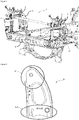
- a cab assembly (1) used in cabs of heavy commercial vehicles and provides to dampen a portion of the energy generated when the cab is exposed to an impact, comprises basically;
- tehre is at least a chassis (2).
- the said chassis (2) is in the form of a framework of the heavy commercial vehicle and carries the cab and the trailer.
- the chassis (2) is also linked with the wheels via the axle.
- the chassis (2) has an extension (2.1) that is preferably formed for mounting the tower bracket (5).
- there is a cab stabilizer rod (3) In the driver's cab assembly in this embodiment of the invention, there is a cab stabilizer rod (3).
- the said cab stabilizer rod (3) allows the cab to be subjected to centrifugal forces at minimum levels during cornering of the vehicle.
- the cab stabilizer rod (3) keeps the tilting angle of the cab at minimum value during cornering of the vehicle.
- the cab stabilizer rod (3) is connected on its one side to the suspension (4).
- the suspension (4) is formed to minimize the exposure of the cab to the vibrations due to the road.
- the suspension (4) dampens the vibrations because of the rough road conditions and provides to keep the comfort of the cab as well as fof the passengers in the cab in this way at a maximum level.
- a tower bracket (5) In a cab assembly (1) according to an embodiment of the invention, the connection of the chassis (2) to the stabilizer rod (3) and to the suspension (4) is provided by means of a tower bracket (5).
- Said tower bracket (5) is mounted to the chassis (2) on one side and to the cab stabilizer rod (3) on the other side.
- the tower bracket (5) as such serves as a bracket which forms a connection between the cab stabilizer rod (3) and the chassis (2).
- the tower bracket (5) in this embodiment of the invention preferably consists of an upper connection region (5.1) and a lower connection region (5.2).
- Tower bracket (5) is mounted to cab stabilizer rod (3) from the upper connection region (5.1) and to the chassis (2) from the lower conneciton region (5.2).
- the lower connection region (5.2) of the tower bracket (5) is fitted on the said extensions (2.1) and preferably, each of the tower bracket (5) and the chassis (2) are fixed to each other by means of a connecting element (A).
- the upper connection region (5.1) is fixed to the cab stabilizer rod (3) by means of a connecting element (A).
- First connection area (5.2.1) in this embodiment of the invention is on the side which is closer to the suspension (4), however the second connection area (5.2.2) is on the side, which is more distal to the suspension (4).
- One of the extensions (2.1) in this embodiment of the invention is vertically aligned with the first connection area (5.2.1) and the other one is vertically aligned with the second connection area (5.2.2).
- the first slot (5.2.1.1) in this embodiment of the invention is preferably opened to position the tower bracket and maintain the said position of the tower bracket (5) that was formed to provide the connection of chassis (2) and cab stabilizer rod (3).
- a connecting element (A) is passed through the first slot (5.2.1.1) and the tower bracket (5) and the extension (2.1) are rigidly secured to each other by means of said connecting element (A).
- Said second slot (5.2.1.2) was opened such that it will be closer to the chassis (2) and and suspension (4) relative to the first slot (5.2.1.1).
- the angle between the axis passing through the center points of first slot (5.2.1.1) and second slot (5.2.1.2) and the ground plane is seventy degrees.
- first slot (5.2.1.1) and second slot (5.2.1.2) can be changed as preferred.
- the diameters of first slot (5.2.1.1) and second slot (5.2.1.2) are almost same.
- a channel (5.2.1.3) is opened between the first slot (5.2.1.1) and the second slot (5.2.1.2).
- Said channel (5.2.1.3) is opened so that its size is smaller than the diameters of the first slot (5.2.1.1) and the second slot (5.2.1.2).
- the length of channel (5.2.1.3) is as much as the distance between the first slot (5.2.1.1) and the second slot (5.2.1.2). As the distance between the first slot (5.2.1.1) and the second slot (5.2.1.2) is increased, the length of the channel (5.2.1.3) and as a matter of course the amount of energy to be damped can be increased.
- the main reason for the fact that the opening of the channel (5.2.1.3) is smaller than the diameter of the first slot (5.2.1.1) and the second slot (5.2.1.2) is the forcing of connecting element (A) in the process of progressing from the first slot (5.2.1.1) to the second slot (5.2.1.2) and thus damping the energy.
- this force also acts on the tower bracket (5) by means of the cab stabilizer rod (3).
- a first slot (5.2.1.1), a second slot (5.2.1.2) and a channel (5.2.1.3) are formed in the first connection area (5.2.1) of the tower bracket (5).
- the connecting element (A) which is seated in the first slot (5.2.1.1), tends to move towards the second slot (5.2.1.2) and it meets with the channel (5.2.1.3) during this process.
- the connecting element (A) encounters a resistance during its progression from the first slot (5.2.1.1) to the second slot (5.2.1.2) because the size of the channel (5.2.1.3) opening is smaller than the first slot (5.2.1.1) and the connecting element (A). This resistance absorbs a portion of the impact energy that the cab has due to the applied force and thus reduces the effect of impact on the cab.
- a cabinet assembly (1) in an embodiment of the invention is realized as follows.
- serious fatalities are usually experienced as a result of a frontal collision. For this reason, it is supremely important to keep the safety of the cab at a maximum level.
- the impact energy is transmitted via cab and suspension (4) and damped.
- the cab and the chassis work simultaneously and a poriton of the total energy is transferred to cab side and the remaining portion is transmitted to chassis (2) via suspension (4).
- Said crash energy applies force to a plurality of components after the first contact with the cab and is finally transferred to tower bracket (5) via cab stabilizer rod (3).
- the damping of the force exerted on the cab can be changed in a preferred amount.
Landscapes
- Engineering & Computer Science (AREA)
- Chemical & Material Sciences (AREA)
- Combustion & Propulsion (AREA)
- Transportation (AREA)
- Mechanical Engineering (AREA)
- Body Structure For Vehicles (AREA)
Claims (6)
- Kabinenanordnung (1), die in Kabinen von schweren Nutzfahrzeugen verwendet wird und dafür sorgt, einen Teil der Energie zu dämpfen, die erzeugt wird, wenn die Kabine einem Aufprall ausgesetzt ist, umfassend grundsätzlich;- die Kabine und mindestens ein Chassis (2), das die Hauptstruktur unterstützt,- mindestens eine Kabinen-Stabilisatorstange (3), die den Kippwinkel der Kabine beim Abbiegen einer Kurve des Fahrzeugs auf einem Mindestwert hält,- mindestens eine Suspension (4), die die von der Straße induzierten Schwingungen absorbiert, ohne sie auf die Kabine zu übertragen,- eine Säulenstütze (5), die an ihrer einen Seite mit dem Chassis (2) und an ihrer anderen Seite mit der Kabinen-stabilisatorstange (3) verbunden ist, die mit der Suspension (4) zusammenhängt, die die Bewegung der Kabinen-stabilisatorstange (3) und die durch sie ausgeübte Kraft dämpft, wenn eine plötzliche Kraft aus einer beliebigen Richtung auf die Kabine einwirkt, und an der mindestens ein abgerundeter erster Schlitz (5.2.1.1), mindestens ein abgerundeter zweiter Schlitz (5.2.1.2) und mindestens ein Kanal (5.2.1.3) geöffnet ist,- wobei der zweite Schlitz (5.2.1.2) mit dem ersten Schlitz (5.2.1.1) durch den Kanal (5.2.1.3) verbunden ist, der eine geringere Größe als der Durchmesser des ersten Schlitzes (5.2.1.1) aufweist,- wobei die Säulenstütze (5), die einen unteren Verbindungsbereich (5.2) aufweist, einen ersten Verbindungsbereich (5.2.1) auf der Seite, die näher an der Suspension (4) ist, und einen zweiten Verbindungsbereich (5.2.2) auf der Seite, die weiter von der Suspension (4) entfernt ist, umfasst,und gekennzeichnet durch• wobei der erste Verbindungsbereich (5.2.1), der den ersten Schlitz (5.2.1.1), den zweiten Schlitz (5.2.1.2) und den zwischen dem ersten Schlitz (5.2.1.1) und dem zweiten Schlitz (5.2.1.2) angeordneten Kanal (5.2.1.3) aufweist und dessen Größe kleiner ist als der Durchmesser des ersten Schlitzes (5.2.1.1) und des zweiten Schlitzes (5.2.1.2)• den ersten Schlitz (5.2.1.1) auf derjenigen Seite, die in Bezug auf die Kabinen-stabilisatorstange (3) nahe am Chassis (2) liegt, und wobei der Winkel zwischen der Linie, die durch die durch den Mittelpunkt desselben verlaufende Achse und durch die durch den Mittelpunkt des zweiten Schlitzes (5.2.1.2) verlaufende Achse gebildet wird, und der Grundebene siebzig Grad beträgt,• wobei der zweite Schlitz (5.2.1.2) die gleiche Größe wie der erste Schlitz (5.2.1.1) aufweist,• den Kanal (5.2.1.3), der aufgrund seiner Größe bei der Bewegung des Verbindungselements (A) vom ersten Schlitz (5.2.1.1) zum zweiten Schlitz (5.2.1.2 ) eine Kraft entgegen der Bewegungsrichtung des Verbindungselements (A) ausübt, wenn eine Kraft durch den Kabinenstabilisator (3) auf die Säulenstütze (5) ausgeübt wird, und dadurch den Durchgang des Verbindungselements (A) erzwingt und die Aufprallenergie teilweise absorbiert.
- Kabinenanordnung (1) nach Anspruch 1, gekennzeichnet durch die Säulenstütze (5), die mit dem oberen Verbindungsbereich (5.1) an der Kabinen-stabilisatorstange (3) und mit dem unteren Verbindungsbereich (5.2) am Chassis (2) befestigt ist und deren unterer Verbindungsbereich (5.2) mittels eines Verbindungselements (A) an den Extensionen (2.1) am Chassis (2) angebracht ist.
- Kabinenanordnung (1) nach Anspruch 1, gekennzeichnet durch den ersten Schlitz (5.2.1.1), der geöffnet wird, um die Säulenstütze (5) zu positionieren und die besagte Position der Säulenstütze beizubehalten, die gebildet wurde, um die Verbindung von Chassis (2) und Kabinen-stabilisatorstange (3) vorzusehen.
- Kabinenanordnung (1) nach Anspruch 1, gekennzeichnet durch den zweiten Schlitz (5.2.1.2), der in einem Abschnitt nahe dem ersten Schlitz (5.2.1.1) geöffnet ist, so dass er relativ zum ersten Schlitz (5.2.1.1) winkelmäßig näher am Chassis (2) und an der Suspension (4) wird.
- Kabinenanordnung (1) nach Anspruch 1, gekennzeichnet durch den zwischen dem ersten Schlitz (5.2.1.1) und dem zweiten Schlitz (5.2.1.2) angeordneten Kanal (5.2.1.3), der mit einer Öffnung ausgebildet ist, die kleiner ist als die Durchmesser des ersten Schlitzes (5.2.1.1) und des zweiten Schlitzes (5.2.1.2) und dessen Länge so groß ist wie der Abstand zwischen dem ersten Schlitz (5.2.1.1) und dem zweiten Schlitz (5.2.1.2).
- Kabinenanordnung (1) nach Anspruch 1, gekennzeichnet durch die Säulenstütze (5), die durch eine von der Kabinen-stabilisatorstange (3) aufgebrachte Kraft zur Drehung im Uhrzeigersinn um die Mittelachse des Bolzenschlitzes (5.2.2.1) im zweiten Verbindungsbereich (5.2.2) gezwungen wird.
Applications Claiming Priority (1)
| Application Number | Priority Date | Filing Date | Title |
|---|---|---|---|
| TR2017/17177A TR201717177A2 (tr) | 2017-11-03 | 2017-11-03 | Bi̇r kabi̇n komplesi̇ |
Publications (2)
| Publication Number | Publication Date |
|---|---|
| EP3480084A1 EP3480084A1 (de) | 2019-05-08 |
| EP3480084B1 true EP3480084B1 (de) | 2021-07-14 |
Family
ID=63965085
Family Applications (1)
| Application Number | Title | Priority Date | Filing Date |
|---|---|---|---|
| EP18201421.7A Active EP3480084B1 (de) | 2017-11-03 | 2018-10-19 | Anordnung eines lkw-fahrerhauses |
Country Status (2)
| Country | Link |
|---|---|
| EP (1) | EP3480084B1 (de) |
| TR (1) | TR201717177A2 (de) |
Families Citing this family (2)
| Publication number | Priority date | Publication date | Assignee | Title |
|---|---|---|---|---|
| US12691955B2 (en) * | 2023-02-17 | 2026-07-28 | Oshkosh Corporation | Vehicle with impact-mitigating cab |
| CN117644916B (zh) * | 2023-12-29 | 2026-06-30 | 一汽解放汽车有限公司 | 车辆及其车身前悬置连接装置 |
Family Cites Families (8)
| Publication number | Priority date | Publication date | Assignee | Title |
|---|---|---|---|---|
| SE454077B (sv) | 1985-08-21 | 1988-03-28 | Saab Scania Ab | Anordning for upphengning av en framat tippbar forarhytt vid fordon |
| JP3511358B2 (ja) * | 1998-02-23 | 2004-03-29 | 日野自動車株式会社 | 衝撃吸収装置 |
| DE19831329B4 (de) | 1998-07-13 | 2019-04-11 | Man Truck & Bus Ag | Vordere Lagerung eines kippbaren Fahrerhauses eines Lastkraftwagens |
| JP5012906B2 (ja) * | 2007-02-01 | 2012-08-29 | トヨタ自動車株式会社 | 車両の端部構造 |
| DE102008003488A1 (de) | 2008-01-08 | 2008-07-17 | Daimler Ag | Rahmenkopf für einen Fahrzeugrahmen eines Lastkraftwagens |
| US8985630B2 (en) * | 2013-07-19 | 2015-03-24 | GM Global Technology Operations LLC | Cradle assembly attachable to a vehicle |
| KR101575335B1 (ko) * | 2014-08-13 | 2015-12-07 | 현대자동차 주식회사 | 전방 차체 보강구조 |
| CN107074287B (zh) * | 2014-09-17 | 2018-11-27 | 康斯博格汽车股份公司 | 驾驶室在发动机上的货车 |
-
2017
- 2017-11-03 TR TR2017/17177A patent/TR201717177A2/tr unknown
-
2018
- 2018-10-19 EP EP18201421.7A patent/EP3480084B1/de active Active
Non-Patent Citations (1)
| Title |
|---|
| None * |
Also Published As
| Publication number | Publication date |
|---|---|
| EP3480084A1 (de) | 2019-05-08 |
| TR201717177A2 (tr) | 2019-05-21 |
Similar Documents
| Publication | Publication Date | Title |
|---|---|---|
| US5251932A (en) | Front body structure of automotive vehicle | |
| EP1373025B1 (de) | Anordnung für unterfahrschutz in fahrzeugen | |
| US5244053A (en) | Structure of automotive vehicle suspension | |
| EP0844939B1 (de) | Seitenairbag-ersatzsystem eines fahrzeugsitzes bei pkw und lkw | |
| EP1927524B1 (de) | Zug mit aufprallenergieabsorbierenden Elementen zwischen den einzelnen Fahrzeugen | |
| JP2008546587A (ja) | 自動車のフロント用の案内された下方領域 | |
| US11873024B2 (en) | Suspension subframe structure | |
| EP3480084A1 (de) | Anordnung eines lkw-fahrerhauses | |
| US12275454B2 (en) | Vehicle frame assembly having an energy absorbing device | |
| JP6034487B2 (ja) | 係合手段と荷重吸収手段を有して懸架された運転者ユニットを備える車両 | |
| EP0213098A2 (de) | Einrichtung zum Aufhängen einer vorwärts kippbaren Kabine auf einem Fahrzeug | |
| EP1604869B1 (de) | Stossfängersystem für ein Kraftfahrzeug | |
| US20230286587A1 (en) | Front structure for a utility vehicle, preferably for a lorry | |
| US8007033B2 (en) | Truck comprising a retaining system for the cab in case of a collision | |
| EP1968845B1 (de) | Aufhängungseinheit und industriefahrzeug damit | |
| JPH10147255A (ja) | 車両及びそのレインフォース | |
| CN106005012A (zh) | 一种汽车及其车架 | |
| EP3495247B1 (de) | Kabinenanordnung | |
| CN103998295B (zh) | 用于钻撞防护设备的防撞梁 | |
| US20240149763A1 (en) | Vehicle seat mounting device and method of use | |
| US20090102209A1 (en) | Arrangement For Underrun Protection In Vehicles | |
| NL2035670B1 (en) | An electric vehicle. | |
| CN113646488B (zh) | 后悬架安装总成 | |
| US7396065B2 (en) | Automotive vehicle seat for absorbing side impact energy | |
| JP2009530148A (ja) | チルト式運転室の取付けシステム |
Legal Events
| Date | Code | Title | Description |
|---|---|---|---|
| PUAI | Public reference made under article 153(3) epc to a published international application that has entered the european phase |
Free format text: ORIGINAL CODE: 0009012 |
|
| STAA | Information on the status of an ep patent application or granted ep patent |
Free format text: STATUS: THE APPLICATION HAS BEEN PUBLISHED |
|
| AK | Designated contracting states |
Kind code of ref document: A1 Designated state(s): AL AT BE BG CH CY CZ DE DK EE ES FI FR GB GR HR HU IE IS IT LI LT LU LV MC MK MT NL NO PL PT RO RS SE SI SK SM TR |
|
| AX | Request for extension of the european patent |
Extension state: BA ME |
|
| STAA | Information on the status of an ep patent application or granted ep patent |
Free format text: STATUS: REQUEST FOR EXAMINATION WAS MADE |
|
| 17P | Request for examination filed |
Effective date: 20190902 |
|
| RBV | Designated contracting states (corrected) |
Designated state(s): AL AT BE BG CH CY CZ DE DK EE ES FI FR GB GR HR HU IE IS IT LI LT LU LV MC MK MT NL NO PL PT RO RS SE SI SK SM TR |
|
| STAA | Information on the status of an ep patent application or granted ep patent |
Free format text: STATUS: EXAMINATION IS IN PROGRESS |
|
| 17Q | First examination report despatched |
Effective date: 20200616 |
|
| GRAP | Despatch of communication of intention to grant a patent |
Free format text: ORIGINAL CODE: EPIDOSNIGR1 |
|
| STAA | Information on the status of an ep patent application or granted ep patent |
Free format text: STATUS: GRANT OF PATENT IS INTENDED |
|
| INTG | Intention to grant announced |
Effective date: 20210305 |
|
| RIC1 | Information provided on ipc code assigned before grant |
Ipc: B62D 33/06 20060101ALI20210222BHEP Ipc: B62D 33/067 20060101ALN20210222BHEP Ipc: B62D 21/15 20060101AFI20210222BHEP |
|
| GRAS | Grant fee paid |
Free format text: ORIGINAL CODE: EPIDOSNIGR3 |
|
| GRAA | (expected) grant |
Free format text: ORIGINAL CODE: 0009210 |
|
| STAA | Information on the status of an ep patent application or granted ep patent |
Free format text: STATUS: THE PATENT HAS BEEN GRANTED |
|
| AK | Designated contracting states |
Kind code of ref document: B1 Designated state(s): AL AT BE BG CH CY CZ DE DK EE ES FI FR GB GR HR HU IE IS IT LI LT LU LV MC MK MT NL NO PL PT RO RS SE SI SK SM TR |
|
| REG | Reference to a national code |
Ref country code: GB Ref legal event code: FG4D |
|
| REG | Reference to a national code |
Ref country code: IE Ref legal event code: FG4D |
|
| REG | Reference to a national code |
Ref country code: DE Ref legal event code: R096 Ref document number: 602018020013 Country of ref document: DE |
|
| REG | Reference to a national code |
Ref country code: AT Ref legal event code: REF Ref document number: 1410422 Country of ref document: AT Kind code of ref document: T Effective date: 20210815 |
|
| REG | Reference to a national code |
Ref country code: LT Ref legal event code: MG9D |
|
| REG | Reference to a national code |
Ref country code: NL Ref legal event code: MP Effective date: 20210714 |
|
| REG | Reference to a national code |
Ref country code: AT Ref legal event code: MK05 Ref document number: 1410422 Country of ref document: AT Kind code of ref document: T Effective date: 20210714 |
|
| PG25 | Lapsed in a contracting state [announced via postgrant information from national office to epo] |
Ref country code: HR Free format text: LAPSE BECAUSE OF FAILURE TO SUBMIT A TRANSLATION OF THE DESCRIPTION OR TO PAY THE FEE WITHIN THE PRESCRIBED TIME-LIMIT Effective date: 20210714 Ref country code: FI Free format text: LAPSE BECAUSE OF FAILURE TO SUBMIT A TRANSLATION OF THE DESCRIPTION OR TO PAY THE FEE WITHIN THE PRESCRIBED TIME-LIMIT Effective date: 20210714 Ref country code: ES Free format text: LAPSE BECAUSE OF FAILURE TO SUBMIT A TRANSLATION OF THE DESCRIPTION OR TO PAY THE FEE WITHIN THE PRESCRIBED TIME-LIMIT Effective date: 20210714 Ref country code: RS Free format text: LAPSE BECAUSE OF FAILURE TO SUBMIT A TRANSLATION OF THE DESCRIPTION OR TO PAY THE FEE WITHIN THE PRESCRIBED TIME-LIMIT Effective date: 20210714 Ref country code: SE Free format text: LAPSE BECAUSE OF FAILURE TO SUBMIT A TRANSLATION OF THE DESCRIPTION OR TO PAY THE FEE WITHIN THE PRESCRIBED TIME-LIMIT Effective date: 20210714 Ref country code: NO Free format text: LAPSE BECAUSE OF FAILURE TO SUBMIT A TRANSLATION OF THE DESCRIPTION OR TO PAY THE FEE WITHIN THE PRESCRIBED TIME-LIMIT Effective date: 20211014 Ref country code: PT Free format text: LAPSE BECAUSE OF FAILURE TO SUBMIT A TRANSLATION OF THE DESCRIPTION OR TO PAY THE FEE WITHIN THE PRESCRIBED TIME-LIMIT Effective date: 20211115 Ref country code: NL Free format text: LAPSE BECAUSE OF FAILURE TO SUBMIT A TRANSLATION OF THE DESCRIPTION OR TO PAY THE FEE WITHIN THE PRESCRIBED TIME-LIMIT Effective date: 20210714 Ref country code: AT Free format text: LAPSE BECAUSE OF FAILURE TO SUBMIT A TRANSLATION OF THE DESCRIPTION OR TO PAY THE FEE WITHIN THE PRESCRIBED TIME-LIMIT Effective date: 20210714 Ref country code: BG Free format text: LAPSE BECAUSE OF FAILURE TO SUBMIT A TRANSLATION OF THE DESCRIPTION OR TO PAY THE FEE WITHIN THE PRESCRIBED TIME-LIMIT Effective date: 20211014 Ref country code: LT Free format text: LAPSE BECAUSE OF FAILURE TO SUBMIT A TRANSLATION OF THE DESCRIPTION OR TO PAY THE FEE WITHIN THE PRESCRIBED TIME-LIMIT Effective date: 20210714 |
|
| PG25 | Lapsed in a contracting state [announced via postgrant information from national office to epo] |
Ref country code: PL Free format text: LAPSE BECAUSE OF FAILURE TO SUBMIT A TRANSLATION OF THE DESCRIPTION OR TO PAY THE FEE WITHIN THE PRESCRIBED TIME-LIMIT Effective date: 20210714 Ref country code: LV Free format text: LAPSE BECAUSE OF FAILURE TO SUBMIT A TRANSLATION OF THE DESCRIPTION OR TO PAY THE FEE WITHIN THE PRESCRIBED TIME-LIMIT Effective date: 20210714 Ref country code: GR Free format text: LAPSE BECAUSE OF FAILURE TO SUBMIT A TRANSLATION OF THE DESCRIPTION OR TO PAY THE FEE WITHIN THE PRESCRIBED TIME-LIMIT Effective date: 20211015 |
|
| REG | Reference to a national code |
Ref country code: DE Ref legal event code: R097 Ref document number: 602018020013 Country of ref document: DE |
|
| PG25 | Lapsed in a contracting state [announced via postgrant information from national office to epo] |
Ref country code: DK Free format text: LAPSE BECAUSE OF FAILURE TO SUBMIT A TRANSLATION OF THE DESCRIPTION OR TO PAY THE FEE WITHIN THE PRESCRIBED TIME-LIMIT Effective date: 20210714 |
|
| PLBE | No opposition filed within time limit |
Free format text: ORIGINAL CODE: 0009261 |
|
| STAA | Information on the status of an ep patent application or granted ep patent |
Free format text: STATUS: NO OPPOSITION FILED WITHIN TIME LIMIT |
|
| REG | Reference to a national code |
Ref country code: CH Ref legal event code: PL |
|
| PG25 | Lapsed in a contracting state [announced via postgrant information from national office to epo] |
Ref country code: SM Free format text: LAPSE BECAUSE OF FAILURE TO SUBMIT A TRANSLATION OF THE DESCRIPTION OR TO PAY THE FEE WITHIN THE PRESCRIBED TIME-LIMIT Effective date: 20210714 Ref country code: SK Free format text: LAPSE BECAUSE OF FAILURE TO SUBMIT A TRANSLATION OF THE DESCRIPTION OR TO PAY THE FEE WITHIN THE PRESCRIBED TIME-LIMIT Effective date: 20210714 Ref country code: RO Free format text: LAPSE BECAUSE OF FAILURE TO SUBMIT A TRANSLATION OF THE DESCRIPTION OR TO PAY THE FEE WITHIN THE PRESCRIBED TIME-LIMIT Effective date: 20210714 Ref country code: EE Free format text: LAPSE BECAUSE OF FAILURE TO SUBMIT A TRANSLATION OF THE DESCRIPTION OR TO PAY THE FEE WITHIN THE PRESCRIBED TIME-LIMIT Effective date: 20210714 Ref country code: CZ Free format text: LAPSE BECAUSE OF FAILURE TO SUBMIT A TRANSLATION OF THE DESCRIPTION OR TO PAY THE FEE WITHIN THE PRESCRIBED TIME-LIMIT Effective date: 20210714 Ref country code: AL Free format text: LAPSE BECAUSE OF FAILURE TO SUBMIT A TRANSLATION OF THE DESCRIPTION OR TO PAY THE FEE WITHIN THE PRESCRIBED TIME-LIMIT Effective date: 20210714 |
|
| 26N | No opposition filed |
Effective date: 20220419 |
|
| REG | Reference to a national code |
Ref country code: BE Ref legal event code: MM Effective date: 20211031 |
|
| PG25 | Lapsed in a contracting state [announced via postgrant information from national office to epo] |
Ref country code: MC Free format text: LAPSE BECAUSE OF FAILURE TO SUBMIT A TRANSLATION OF THE DESCRIPTION OR TO PAY THE FEE WITHIN THE PRESCRIBED TIME-LIMIT Effective date: 20210714 |
|
| PG25 | Lapsed in a contracting state [announced via postgrant information from national office to epo] |
Ref country code: LU Free format text: LAPSE BECAUSE OF NON-PAYMENT OF DUE FEES Effective date: 20211019 Ref country code: IT Free format text: LAPSE BECAUSE OF FAILURE TO SUBMIT A TRANSLATION OF THE DESCRIPTION OR TO PAY THE FEE WITHIN THE PRESCRIBED TIME-LIMIT Effective date: 20210714 Ref country code: BE Free format text: LAPSE BECAUSE OF NON-PAYMENT OF DUE FEES Effective date: 20211031 |
|
| PG25 | Lapsed in a contracting state [announced via postgrant information from national office to epo] |
Ref country code: LI Free format text: LAPSE BECAUSE OF NON-PAYMENT OF DUE FEES Effective date: 20211031 Ref country code: CH Free format text: LAPSE BECAUSE OF NON-PAYMENT OF DUE FEES Effective date: 20211031 |
|
| PG25 | Lapsed in a contracting state [announced via postgrant information from national office to epo] |
Ref country code: FR Free format text: LAPSE BECAUSE OF NON-PAYMENT OF DUE FEES Effective date: 20211031 |
|
| PG25 | Lapsed in a contracting state [announced via postgrant information from national office to epo] |
Ref country code: IE Free format text: LAPSE BECAUSE OF NON-PAYMENT OF DUE FEES Effective date: 20211019 |
|
| GBPC | Gb: european patent ceased through non-payment of renewal fee |
Effective date: 20221019 |
|
| PG25 | Lapsed in a contracting state [announced via postgrant information from national office to epo] |
Ref country code: CY Free format text: LAPSE BECAUSE OF FAILURE TO SUBMIT A TRANSLATION OF THE DESCRIPTION OR TO PAY THE FEE WITHIN THE PRESCRIBED TIME-LIMIT Effective date: 20210714 |
|
| P01 | Opt-out of the competence of the unified patent court (upc) registered |
Effective date: 20230619 |
|
| PG25 | Lapsed in a contracting state [announced via postgrant information from national office to epo] |
Ref country code: HU Free format text: LAPSE BECAUSE OF FAILURE TO SUBMIT A TRANSLATION OF THE DESCRIPTION OR TO PAY THE FEE WITHIN THE PRESCRIBED TIME-LIMIT; INVALID AB INITIO Effective date: 20181019 |
|
| PG25 | Lapsed in a contracting state [announced via postgrant information from national office to epo] |
Ref country code: GB Free format text: LAPSE BECAUSE OF NON-PAYMENT OF DUE FEES Effective date: 20221019 |
|
| PG25 | Lapsed in a contracting state [announced via postgrant information from national office to epo] |
Ref country code: MK Free format text: LAPSE BECAUSE OF FAILURE TO SUBMIT A TRANSLATION OF THE DESCRIPTION OR TO PAY THE FEE WITHIN THE PRESCRIBED TIME-LIMIT Effective date: 20210714 |
|
| PG25 | Lapsed in a contracting state [announced via postgrant information from national office to epo] |
Ref country code: TR Free format text: LAPSE BECAUSE OF FAILURE TO SUBMIT A TRANSLATION OF THE DESCRIPTION OR TO PAY THE FEE WITHIN THE PRESCRIBED TIME-LIMIT Effective date: 20210714 |
|
| PG25 | Lapsed in a contracting state [announced via postgrant information from national office to epo] |
Ref country code: MT Free format text: LAPSE BECAUSE OF FAILURE TO SUBMIT A TRANSLATION OF THE DESCRIPTION OR TO PAY THE FEE WITHIN THE PRESCRIBED TIME-LIMIT Effective date: 20210714 |
|
| PGFP | Annual fee paid to national office [announced via postgrant information from national office to epo] |
Ref country code: DE Payment date: 20251028 Year of fee payment: 8 |