EP3480471B1 - Ventilateur avec tube support - Google Patents
Ventilateur avec tube support Download PDFInfo
- Publication number
- EP3480471B1 EP3480471B1 EP18206950.0A EP18206950A EP3480471B1 EP 3480471 B1 EP3480471 B1 EP 3480471B1 EP 18206950 A EP18206950 A EP 18206950A EP 3480471 B1 EP3480471 B1 EP 3480471B1
- Authority
- EP
- European Patent Office
- Prior art keywords
- blower
- stator
- tube
- shield
- bearing
- Prior art date
- Legal status (The legal status is an assumption and is not a legal conclusion. Google has not performed a legal analysis and makes no representation as to the accuracy of the status listed.)
- Active
Links
Images














Classifications
-
- H—ELECTRICITY
- H02—GENERATION; CONVERSION OR DISTRIBUTION OF ELECTRIC POWER
- H02K—DYNAMO-ELECTRIC MACHINES
- H02K7/00—Arrangements for handling mechanical energy structurally associated with dynamo-electric machines, e.g. structural association with mechanical driving motors or auxiliary dynamo-electric machines
- H02K7/08—Structural association with bearings
- H02K7/083—Structural association with bearings radially supporting the rotary shaft at both ends of the rotor
-
- F—MECHANICAL ENGINEERING; LIGHTING; HEATING; WEAPONS; BLASTING
- F04—POSITIVE - DISPLACEMENT MACHINES FOR LIQUIDS; PUMPS FOR LIQUIDS OR ELASTIC FLUIDS
- F04D—NON-POSITIVE-DISPLACEMENT PUMPS
- F04D29/00—Details, component parts, or accessories
- F04D29/60—Mounting; Assembling; Disassembling
- F04D29/601—Mounting; Assembling; Disassembling specially adapted for elastic fluid pumps
-
- F—MECHANICAL ENGINEERING; LIGHTING; HEATING; WEAPONS; BLASTING
- F04—POSITIVE - DISPLACEMENT MACHINES FOR LIQUIDS; PUMPS FOR LIQUIDS OR ELASTIC FLUIDS
- F04D—NON-POSITIVE-DISPLACEMENT PUMPS
- F04D25/00—Pumping installations or systems
- F04D25/02—Units comprising pumps and their driving means
- F04D25/06—Units comprising pumps and their driving means the pump being electrically driven
- F04D25/0606—Units comprising pumps and their driving means the pump being electrically driven the electric motor being specially adapted for integration in the pump
- F04D25/0613—Units comprising pumps and their driving means the pump being electrically driven the electric motor being specially adapted for integration in the pump the electric motor being of the inside-out type, i.e. the rotor is arranged radially outside a central stator
- F04D25/0646—Details of the stator
-
- F—MECHANICAL ENGINEERING; LIGHTING; HEATING; WEAPONS; BLASTING
- F04—POSITIVE - DISPLACEMENT MACHINES FOR LIQUIDS; PUMPS FOR LIQUIDS OR ELASTIC FLUIDS
- F04D—NON-POSITIVE-DISPLACEMENT PUMPS
- F04D25/00—Pumping installations or systems
- F04D25/02—Units comprising pumps and their driving means
- F04D25/08—Units comprising pumps and their driving means the working fluid being air, e.g. for ventilation
-
- F—MECHANICAL ENGINEERING; LIGHTING; HEATING; WEAPONS; BLASTING
- F04—POSITIVE - DISPLACEMENT MACHINES FOR LIQUIDS; PUMPS FOR LIQUIDS OR ELASTIC FLUIDS
- F04D—NON-POSITIVE-DISPLACEMENT PUMPS
- F04D25/00—Pumping installations or systems
- F04D25/02—Units comprising pumps and their driving means
- F04D25/08—Units comprising pumps and their driving means the working fluid being air, e.g. for ventilation
- F04D25/082—Units comprising pumps and their driving means the working fluid being air, e.g. for ventilation the unit having provision for cooling the motor
-
- F—MECHANICAL ENGINEERING; LIGHTING; HEATING; WEAPONS; BLASTING
- F04—POSITIVE - DISPLACEMENT MACHINES FOR LIQUIDS; PUMPS FOR LIQUIDS OR ELASTIC FLUIDS
- F04D—NON-POSITIVE-DISPLACEMENT PUMPS
- F04D29/00—Details, component parts, or accessories
- F04D29/08—Sealings
- F04D29/083—Sealings especially adapted for elastic fluid pumps
-
- F—MECHANICAL ENGINEERING; LIGHTING; HEATING; WEAPONS; BLASTING
- F04—POSITIVE - DISPLACEMENT MACHINES FOR LIQUIDS; PUMPS FOR LIQUIDS OR ELASTIC FLUIDS
- F04D—NON-POSITIVE-DISPLACEMENT PUMPS
- F04D29/00—Details, component parts, or accessories
- F04D29/40—Casings; Connections of working fluid
- F04D29/403—Casings; Connections of working fluid especially adapted for elastic fluid pumps
-
- F—MECHANICAL ENGINEERING; LIGHTING; HEATING; WEAPONS; BLASTING
- F04—POSITIVE - DISPLACEMENT MACHINES FOR LIQUIDS; PUMPS FOR LIQUIDS OR ELASTIC FLUIDS
- F04D—NON-POSITIVE-DISPLACEMENT PUMPS
- F04D29/00—Details, component parts, or accessories
- F04D29/58—Cooling; Heating; Diminishing heat transfer
- F04D29/5806—Cooling the drive system
-
- F—MECHANICAL ENGINEERING; LIGHTING; HEATING; WEAPONS; BLASTING
- F04—POSITIVE - DISPLACEMENT MACHINES FOR LIQUIDS; PUMPS FOR LIQUIDS OR ELASTIC FLUIDS
- F04D—NON-POSITIVE-DISPLACEMENT PUMPS
- F04D29/00—Details, component parts, or accessories
- F04D29/66—Combating cavitation, whirls, noise, vibration or the like; Balancing
- F04D29/661—Combating cavitation, whirls, noise, vibration or the like; Balancing especially adapted for elastic fluid pumps
- F04D29/663—Sound attenuation
-
- F—MECHANICAL ENGINEERING; LIGHTING; HEATING; WEAPONS; BLASTING
- F04—POSITIVE - DISPLACEMENT MACHINES FOR LIQUIDS; PUMPS FOR LIQUIDS OR ELASTIC FLUIDS
- F04D—NON-POSITIVE-DISPLACEMENT PUMPS
- F04D29/00—Details, component parts, or accessories
- F04D29/66—Combating cavitation, whirls, noise, vibration or the like; Balancing
- F04D29/661—Combating cavitation, whirls, noise, vibration or the like; Balancing especially adapted for elastic fluid pumps
- F04D29/668—Combating cavitation, whirls, noise, vibration or the like; Balancing especially adapted for elastic fluid pumps damping or preventing mechanical vibrations
-
- H—ELECTRICITY
- H02—GENERATION; CONVERSION OR DISTRIBUTION OF ELECTRIC POWER
- H02K—DYNAMO-ELECTRIC MACHINES
- H02K1/00—Details of the magnetic circuit
- H02K1/06—Details of the magnetic circuit characterised by the shape, form or construction
- H02K1/12—Stationary parts of the magnetic circuit
- H02K1/18—Means for mounting or fastening magnetic stationary parts on to, or to, the stator structures
- H02K1/185—Means for mounting or fastening magnetic stationary parts on to, or to, the stator structures to outer stators
-
- H—ELECTRICITY
- H02—GENERATION; CONVERSION OR DISTRIBUTION OF ELECTRIC POWER
- H02K—DYNAMO-ELECTRIC MACHINES
- H02K3/00—Details of windings
- H02K3/46—Fastening of windings on the stator or rotor structure
- H02K3/52—Fastening salient pole windings or connections thereto
- H02K3/521—Fastening salient pole windings or connections thereto applicable to stators only
- H02K3/522—Fastening salient pole windings or connections thereto applicable to stators only for generally annular cores with salient poles
-
- H—ELECTRICITY
- H02—GENERATION; CONVERSION OR DISTRIBUTION OF ELECTRIC POWER
- H02K—DYNAMO-ELECTRIC MACHINES
- H02K5/00—Casings; Enclosures; Supports
- H02K5/04—Casings or enclosures characterised by the shape, form or construction thereof
- H02K5/08—Insulating casings
-
- H—ELECTRICITY
- H02—GENERATION; CONVERSION OR DISTRIBUTION OF ELECTRIC POWER
- H02K—DYNAMO-ELECTRIC MACHINES
- H02K5/00—Casings; Enclosures; Supports
- H02K5/04—Casings or enclosures characterised by the shape, form or construction thereof
- H02K5/12—Casings or enclosures characterised by the shape, form or construction thereof specially adapted for operating in liquid or gas
- H02K5/128—Casings or enclosures characterised by the shape, form or construction thereof specially adapted for operating in liquid or gas using air-gap sleeves or air-gap discs
-
- H—ELECTRICITY
- H02—GENERATION; CONVERSION OR DISTRIBUTION OF ELECTRIC POWER
- H02K—DYNAMO-ELECTRIC MACHINES
- H02K5/00—Casings; Enclosures; Supports
- H02K5/04—Casings or enclosures characterised by the shape, form or construction thereof
- H02K5/16—Means for supporting bearings, e.g. insulating supports or means for fitting bearings in the bearing-shields
- H02K5/173—Means for supporting bearings, e.g. insulating supports or means for fitting bearings in the bearing-shields using bearings with rolling contact, e.g. ball bearings
- H02K5/1732—Means for supporting bearings, e.g. insulating supports or means for fitting bearings in the bearing-shields using bearings with rolling contact, e.g. ball bearings radially supporting the rotary shaft at both ends of the rotor
-
- H—ELECTRICITY
- H02—GENERATION; CONVERSION OR DISTRIBUTION OF ELECTRIC POWER
- H02K—DYNAMO-ELECTRIC MACHINES
- H02K5/00—Casings; Enclosures; Supports
- H02K5/04—Casings or enclosures characterised by the shape, form or construction thereof
- H02K5/22—Auxiliary parts of casings not covered by groups H02K5/06-H02K5/20, e.g. shaped to form connection boxes or terminal boxes
- H02K5/225—Terminal boxes or connection arrangements
-
- H—ELECTRICITY
- H02—GENERATION; CONVERSION OR DISTRIBUTION OF ELECTRIC POWER
- H02K—DYNAMO-ELECTRIC MACHINES
- H02K5/00—Casings; Enclosures; Supports
- H02K5/24—Casings; Enclosures; Supports specially adapted for suppression or reduction of noise or vibrations
-
- H—ELECTRICITY
- H02—GENERATION; CONVERSION OR DISTRIBUTION OF ELECTRIC POWER
- H02K—DYNAMO-ELECTRIC MACHINES
- H02K7/00—Arrangements for handling mechanical energy structurally associated with dynamo-electric machines, e.g. structural association with mechanical driving motors or auxiliary dynamo-electric machines
- H02K7/14—Structural association with mechanical loads, e.g. with hand-held machine tools or fans
-
- H—ELECTRICITY
- H02—GENERATION; CONVERSION OR DISTRIBUTION OF ELECTRIC POWER
- H02K—DYNAMO-ELECTRIC MACHINES
- H02K9/00—Arrangements for cooling or ventilating
- H02K9/14—Arrangements for cooling or ventilating wherein gaseous cooling medium circulates between the machine casing and a surrounding mantle
-
- A—HUMAN NECESSITIES
- A61—MEDICAL OR VETERINARY SCIENCE; HYGIENE
- A61M—DEVICES FOR INTRODUCING MEDIA INTO, OR ONTO, THE BODY; DEVICES FOR TRANSDUCING BODY MEDIA OR FOR TAKING MEDIA FROM THE BODY; DEVICES FOR PRODUCING OR ENDING SLEEP OR STUPOR
- A61M16/00—Devices for influencing the respiratory system of patients by gas treatment, e.g. ventilators; Tracheal tubes
- A61M16/0057—Pumps therefor
- A61M16/0066—Blowers or centrifugal pumps
-
- A—HUMAN NECESSITIES
- A61—MEDICAL OR VETERINARY SCIENCE; HYGIENE
- A61M—DEVICES FOR INTRODUCING MEDIA INTO, OR ONTO, THE BODY; DEVICES FOR TRANSDUCING BODY MEDIA OR FOR TAKING MEDIA FROM THE BODY; DEVICES FOR PRODUCING OR ENDING SLEEP OR STUPOR
- A61M16/00—Devices for influencing the respiratory system of patients by gas treatment, e.g. ventilators; Tracheal tubes
- A61M16/10—Preparation of respiratory gases or vapours
- A61M16/12—Preparation of respiratory gases or vapours by mixing different gases
- A61M16/122—Preparation of respiratory gases or vapours by mixing different gases with dilution
-
- A—HUMAN NECESSITIES
- A61—MEDICAL OR VETERINARY SCIENCE; HYGIENE
- A61M—DEVICES FOR INTRODUCING MEDIA INTO, OR ONTO, THE BODY; DEVICES FOR TRANSDUCING BODY MEDIA OR FOR TAKING MEDIA FROM THE BODY; DEVICES FOR PRODUCING OR ENDING SLEEP OR STUPOR
- A61M2202/00—Special media to be introduced, removed or treated
- A61M2202/02—Gases
- A61M2202/0208—Oxygen
-
- A—HUMAN NECESSITIES
- A61—MEDICAL OR VETERINARY SCIENCE; HYGIENE
- A61M—DEVICES FOR INTRODUCING MEDIA INTO, OR ONTO, THE BODY; DEVICES FOR TRANSDUCING BODY MEDIA OR FOR TAKING MEDIA FROM THE BODY; DEVICES FOR PRODUCING OR ENDING SLEEP OR STUPOR
- A61M2205/00—General characteristics of the apparatus
- A61M2205/33—Controlling, regulating or measuring
- A61M2205/3368—Temperature
-
- A—HUMAN NECESSITIES
- A61—MEDICAL OR VETERINARY SCIENCE; HYGIENE
- A61M—DEVICES FOR INTRODUCING MEDIA INTO, OR ONTO, THE BODY; DEVICES FOR TRANSDUCING BODY MEDIA OR FOR TAKING MEDIA FROM THE BODY; DEVICES FOR PRODUCING OR ENDING SLEEP OR STUPOR
- A61M2205/00—General characteristics of the apparatus
- A61M2205/42—Reducing noise
-
- F—MECHANICAL ENGINEERING; LIGHTING; HEATING; WEAPONS; BLASTING
- F04—POSITIVE - DISPLACEMENT MACHINES FOR LIQUIDS; PUMPS FOR LIQUIDS OR ELASTIC FLUIDS
- F04D—NON-POSITIVE-DISPLACEMENT PUMPS
- F04D25/00—Pumping installations or systems
- F04D25/02—Units comprising pumps and their driving means
- F04D25/06—Units comprising pumps and their driving means the pump being electrically driven
- F04D25/0606—Units comprising pumps and their driving means the pump being electrically driven the electric motor being specially adapted for integration in the pump
-
- F—MECHANICAL ENGINEERING; LIGHTING; HEATING; WEAPONS; BLASTING
- F04—POSITIVE - DISPLACEMENT MACHINES FOR LIQUIDS; PUMPS FOR LIQUIDS OR ELASTIC FLUIDS
- F04D—NON-POSITIVE-DISPLACEMENT PUMPS
- F04D25/00—Pumping installations or systems
- F04D25/02—Units comprising pumps and their driving means
- F04D25/08—Units comprising pumps and their driving means the working fluid being air, e.g. for ventilation
- F04D25/12—Units comprising pumps and their driving means the working fluid being air, e.g. for ventilation the unit being adapted for mounting in apertures
-
- F—MECHANICAL ENGINEERING; LIGHTING; HEATING; WEAPONS; BLASTING
- F04—POSITIVE - DISPLACEMENT MACHINES FOR LIQUIDS; PUMPS FOR LIQUIDS OR ELASTIC FLUIDS
- F04D—NON-POSITIVE-DISPLACEMENT PUMPS
- F04D29/00—Details, component parts, or accessories
- F04D29/05—Shafts or bearings, or assemblies thereof, specially adapted for elastic fluid pumps
- F04D29/056—Bearings
- F04D29/059—Roller bearings
-
- H—ELECTRICITY
- H02—GENERATION; CONVERSION OR DISTRIBUTION OF ELECTRIC POWER
- H02K—DYNAMO-ELECTRIC MACHINES
- H02K15/00—Processes or apparatus specially adapted for manufacturing, assembling, maintaining or repairing of dynamo-electric machines
- H02K15/04—Processes or apparatus specially adapted for manufacturing, assembling, maintaining or repairing of dynamo-electric machines of windings prior to their mounting into the machines
- H02K15/043—Processes or apparatus specially adapted for manufacturing, assembling, maintaining or repairing of dynamo-electric machines of windings prior to their mounting into the machines winding flat conductive wires or sheets
-
- H—ELECTRICITY
- H02—GENERATION; CONVERSION OR DISTRIBUTION OF ELECTRIC POWER
- H02K—DYNAMO-ELECTRIC MACHINES
- H02K2205/00—Specific aspects not provided for in the other groups of this subclass relating to casings, enclosures, supports
- H02K2205/09—Machines characterised by drain passages or by venting, breathing or pressure compensating means
-
- H—ELECTRICITY
- H02—GENERATION; CONVERSION OR DISTRIBUTION OF ELECTRIC POWER
- H02K—DYNAMO-ELECTRIC MACHINES
- H02K2213/00—Specific aspects, not otherwise provided for and not covered by codes H02K2201/00 - H02K2211/00
- H02K2213/03—Machines characterised by numerical values, ranges, mathematical expressions or similar information
-
- Y—GENERAL TAGGING OF NEW TECHNOLOGICAL DEVELOPMENTS; GENERAL TAGGING OF CROSS-SECTIONAL TECHNOLOGIES SPANNING OVER SEVERAL SECTIONS OF THE IPC; TECHNICAL SUBJECTS COVERED BY FORMER USPC CROSS-REFERENCE ART COLLECTIONS [XRACs] AND DIGESTS
- Y10—TECHNICAL SUBJECTS COVERED BY FORMER USPC
- Y10T—TECHNICAL SUBJECTS COVERED BY FORMER US CLASSIFICATION
- Y10T29/00—Metal working
- Y10T29/49—Method of mechanical manufacture
- Y10T29/49002—Electrical device making
- Y10T29/49009—Dynamoelectric machine
Definitions
- the present invention relates to a method for forming windings of a stator assembly in a blower, comprising: providing a stationary portion for the blower including a tube adapted to support a rotor; and using the tube as a mandrel to form the windings of the stator assembly.
- Blowers generally include two main parts: a rotating part, namely an impeller and shaft; and a stationary part that defines a fluid flow path, typically a chamber such as a volute.
- Bearings are usually employed in pairs and in coaxial arrangements to support the rotating part, e.g., shaft. Ideally, the two bearings are located by a stationary member that constrains the two bearings in perfect axial alignment. Real world designs are less than perfect and, therefore, compromise bearing performance.
- a widely employed bearing suspension mode involves holding each bearing within a separate housing structure and fitting those housing structures together to approximate a coaxial bearing arrangement.
- the second constraint is driven by the need to place items (such as a rotor/stator) between bearing pairs.
- items such as a rotor/stator
- a consequence of multipart housings is that they accumulate unwanted tolerance build-up at each faying or joint surface, and, as such, each component part must be, or is ideally, precisely shaped so that the accumulated dimensional errors remain within acceptable range.
- US 5 343 104 A describes a fan motor having a structure with a tube supporting the winding of the motor.
- the inventors of the present invention have devised an improved arrangement that does not suffer from the above-mentioned drawbacks.
- One aspect of the invention relates to a method for forming windings of a stator assembly in a blower.
- the method includes providing a stationary portion for the blower including a tube adapted to support a rotor, and using the tube as a mandrel to form the windings of the stator assembly.
- NMVV treatment apparatus e.g., positive airway pressure (PAP) devices or flow generators
- PAP positive airway pressure
- CPAP e.g., in the range of 4-28 cmH 2 O, at flow rates of up to 180 L/min (measured at the mask)
- variable pressure therapy e.g., low range of 2-6 cmH 2 O and high range of 6-30 cmH 2 O
- mechanical ventilation and assisted respiration but it is to be understood that the features of the invention will have application to other fields of application where blowers are used, such as vacuum cleaners, cooling equipment in computers and HVAC devices such as those found in buildings and vehicles. That is, the blowers described herein may have application in both positive pressure and negative pressure applications.
- blower embodiment below is described as including two stages, it should be appreciated that each embodiment may a single stage design or other multiple stage designs, e.g., three, four, or more stages.
- air pump and "blower” may be used interchangeably.
- the phrase “stationary part” may be taken to include “volute”.
- air may be taken to include breathable gases, for example air with supplemental oxygen. It is also acknowledged that the blowers described herein may be designed to pump fluids other than air.
- Figs. 1-1 to 1-4 illustrate a blower 10 according to an embodiment of the present disclosure.
- the blower 10 includes two stages with two corresponding impellers 50, 52.
- one impeller 50 is positioned on one side of the motor 40 and the other impeller 52 is positioned on the other side of the motor 40.
- other suitable impeller arrangements are possible, e.g., two impellers positioned on the same side of the motor.
- the blower 10 may include a single stage design or other multiple stage designs, e.g., two or more impellers.
- a stationary portion of the blower 10 includes a housing 20 with first and second housing parts 22, 24, a stator component 30 including stator vanes 32, and first and second shields 60, 70.
- a rotating portion of the blower 10 includes a rotatable shaft or rotor 80 adapted to be driven by motor 40 and first and second impellers 50, 52 provided to end portions of the shaft 80.
- the motor 40 includes a magnet 42 (e.g., two pole magnet) provided to shaft 80 and a stator assembly 44 to cause spinning movement of the shaft 80 via the magnet 42.
- the motor may be operated without the use of rotor position sensors, e.g., no Hall sensors on printed circuit board (PCB), which may reduce the number of wires, e.g., 3 wires.
- PCB printed circuit board
- the stator assembly 44 includes windings 46 and a stator or stator lamination stack 48 (e.g., slotless or toothless) provided to the windings 46. Further details of coil winding is disclosed in U.S. Provisional Application No. 60/877,373, filed December 28, 2006 , which is incorporated herein by reference in its entirety.
- the blower 10 is generally cylindrical and has an inlet 26 provided by the first housing part 22 at one end and an outlet 28 provided by the second housing part 24 at the other end.
- the blower 10 is operable to draw a supply of gas into the housing 20 through the inlet 26 and provide a pressurized flow of gas at the outlet 28.
- the blower 10 has axial symmetry with both the inlet 26 and outlet 28 aligned with an axis 15 of the blower 10.
- gas enters the blower 10 axially at one end and leaves the blower 10 axially at the other end.
- Such arrangement may provide relatively low noise in use, e.g., due to axial symmetry and/or low volute turbulence.
- Exemplary embodiments of such blowers are disclosed in PCT Application No. PCT/AU2007/000719, filed May 24, 2007 , which is incorporated herein by reference in its entirety.
- the blower 10 may be relatively compact and have an overall diameter D of about 50-60 mm, e.g., 53 mm, and an overall length L of about 45-55 mm, e.g., 52 mm.
- an overall diameter D of about 50-60 mm, e.g., 53 mm
- an overall length L of about 45-55 mm, e.g., 52 mm.
- other suitable sizes are possible.
- the stator component 30 includes a base 34, an annular flange 36 extending from the base 34, a tube or bearing tube 38, and a plurality of stator vanes 32.
- the stator component 30 is integrally formed (e.g., injection molded of plastic material) as a one-piece structure.
- the stator component 30 may be constructed in other suitable manners.
- annular flange 36 is sandwiched between the first and second housing parts 22, 24 to support the stator component 30 within the housing 20.
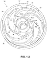
- the plurality of stator vanes 32 are structured to direct airflow towards an orifice 35 in the base 34.
- the stator component 30 has six stator vanes 32.
- Each vane 32 is substantially identical and has a generally spiral shape.
- each vane 32 includes an inner portion 37 (adjacent the tube 38) and an outer portion 39.
- the inner portion 37 is recessed (e.g., reduced in height) with respect to the outer portion 39.
- the stator component may have other suitable structure to condition the airflow between stages.
- the interior surface 90 of the tube 38 is structured to retain and align the bearings 100, 102 that rotatably support the shaft 80.
- the tube 38 encloses the magnet 42 on the shaft 80, which is aligned in close proximity to the stator assembly 44 provided along an exterior surface 92 of the tube 38.
- the tube 38 has at least a portion that is sufficiently "magnetically transparent" to allow a magnetic field to pass through it, which allows the stator assembly 44 to act on the magnet 42 positioned within the tube 38 without significant loss of flux density and/or increased heat, if any.
- such "magnetic transparency” may be provided by one or more of the tube's material properties, e.g., non-electrically conductive, non-magnetic, and/or thermally conductive.
- the tube may include one or more of the following: anisotropic materials, composite (e.g., base polymers (e.g., LCP and PPS) with either ceramic fillers, graphite fillers, and/or other fillers), heterogeneous fill, insert molding, plating, ion implantation, etc.
- such "magnetic transparency” may be provided by the tube's structural properties, e.g., one or more perforations, slits, etc. in the tube.
- the tube may include one or more of these properties and/or a sufficient degree of these properties to provide sufficient "magnetic transparency.” Further details of a magnetically transparent tube are disclosed in U.S. Provisional Application Nos. 60/853,778, filed October 24, 2006 , and 60/929,558, filed July 3, 2007 , each of which is incorporated herein by reference in its entirety.
- the tube has a circular cross-sectional configuration along its length.
- the tube may have other suitable shapes, e.g., square, polygonal, conical, etc.
- the tube may include one or more parts, e.g., multi-part construction.
- the tube may have different material properties along its length or circumference, e.g., different levels or regions of "magnetic transparency", “non-electrical conductivity”, and/or "thermal conductivity.”
- the tube 38 is structured such that mixed bearing sizes may be used. As shown in Fig. 1-1 , the upper end of the tube 38 is structured to support bearing 100 and the lower end of the tube 38 is structured to support bearing 102 having a smaller size or diameter than bearing 100.
- the upper end of the tube 38 includes an annular surface 90(1) defining a diameter d1 and adapted to support bearing 100.
- the lower end of the tube 38 includes an annular surface 90(2) defining a smaller diameter d2 and adapted to support bearing 102.
- the one-piece tube 38 provides accurate bore-to-bore alignment which provides accurate bearing-to-bearing alignment.
- the tube may be manufactured such that upper and lower ends of the tube are adapted to support bearings of the same size.
- a tube structured to support mixed bearing sizes may facilitate a line of draw molding process.
- the tube may be structured to support one or more bearings, and the bearings may include other suitable configurations, e.g., fluid bearings.
- the tube may be structured such that the upper end of the tube is structured to support a bearing having a smaller size or diameter than the bearing supported at the lower end of the tube (e.g., blower with a larger inlet diameter to the second impeller).
- a sloped surface 90(3) may be provided between surfaces 90(1) and 90(2) to guide the shaft 80 (with bearings 100, 102 provided to respective end portions) into the lower end of the tube 38.
- the smaller bearing side of the shaft 80 may be inserted into or "dropped into” the tube 38 through the upper end of the tube 38.
- the sloped surface 90(3) will guide the bearing 102 into engagement with surface 90(2) having a reduced diameter.
- the bearing 102 is self-guided into its operative position.
- the lower end of the tube 38 includes a flange 94 that provides a stop or support for the bearing 102 at the lower end.
- the upper end of the tube 38 is adapted to engage the shield or rotor cap 60, which provides a stop for the bearing 100 at the upper end and hence retains the shaft 80 within the tube 38.
- Washers 104 and a spring or biasing element 106 may be provided between the bearing 102 and the rotor magnet 42 to maintain alignment of the rotor magnet 42 with the stator assembly 44 and/or provide a pre-load to the inner race of bearing 102.
- end portions of the shaft 80 may include one or more bonding grooves for securing the bearings 100, 102 in an operative position
- an intermediate portion of the shaft 80 may include one or more bonding grooves (e.g., helical bonding grooves) for securing the magnet 42 in an operative position.
- the bonding grooves may be provided to selected portions of the shaft (e.g., ends and middle of the shaft) or the bonding grooves may extend along the entire length of the shaft.
- an intermediate portion of the shaft may include threads (e.g., extending outwardly from the exterior surface of the shaft) for securing the magnet in an operative position.
- the stator assembly 44 is provided along the exterior surface 92 of the tube 38.
- the stator component 30 and first shield 60 cooperate to support and maintain the stator assembly 44 in an operative position.
- the windings 46 of the stator assembly 44 are encased or supported by the recessed, inner portion 37 of the stator vanes 32, and the stack 48 of the stator assembly 44 is encased or supported by the outer portion 39 of the stator vanes 32.
- the shield 60 includes an annular flange 64 that encloses an upper portion of the windings 46 and engages an upper side 47 or an exterior surface 49 of the stack 48 (e.g., left side of Fig. 1-1 shows flange 64 engaging upper side 47 of stack 48 and right side of Fig. 1-1 shows flange 64 engaging exterior surface 49 of stack 48).
- stator component 30 and shield 60 cooperate to enclose and sandwich the stator assembly 44.
- the exterior surface 49 of the stack 48 and/or the annular flange 64 engaging the stack 48 is exposed to the flow of gas.
- This arrangement allows forced-convection cooling of the stack 48 as gas flows through the housing 20 in use. In addition, this arrangement may assist in heating the gas or patient air.
- windings 46 of the stator assembly 44 are exposed to the flow of gas to allow cooling and assist in heating the gas or patient air.
- stator component 30 and shield 60 may be thermally conductive (e.g., add graphite or other filler to polymer material) to help with heat conduction.
- the first or upper shield 60 includes a disk portion 62 and the annular flange 64 extending from the outer edge of the disk portion 62 and adapted to engage the stator assembly 44 as described above.
- the outer edge of the disk portion 62 substantially aligns with or extends radially beyond the outer edge of the impeller 50.
- the shield 60 provides a narrow annular gap 110 between the annular flange 64 and the side wall of the housing part 22, which is sufficient to direct gas into the stator component 30.
- the disk portion 62 includes an opening 66 that allows the shaft 80 to extend therethrough.
- An annular flange or projection 68 is provided along the opening 66 that is structured to engage the upper end of the tube 38 of the stator component 30, e.g., with a friction fit.
- the annular flange 64 includes one or more tabs 65 that are adapted to engage within respective slots 23 defined between the first housing part 22 and the stator component 30 (e.g., see Figs. 1-1 and 1-4 ). As shown in Fig. 1-4 , the shield 60 includes three tabs 65 that are received in respective slots 23 defined between the first housing part 22 and the stator component 30. However, any suitable number of slots/tabs may be provided. Also, it should be appreciated that the slots/tabs may be optional and the shield 60 may be supported within the housing in other suitable manners.
- the second or lower shield 70 includes a plurality of stator vanes 72, e.g., between 2 and 100 stator vanes, to direct airflow towards the outlet 28.
- the shield 70 has 7 stator vanes.
- Each vane 72 is substantially identical and has a generally spiral shape.
- each vane 72 includes an inner portion 73 (adjacent the hub 74) and an outer portion 75.
- the outer portion 75 is recessed (e.g., reduced in height) with respect to the inner portion 73, and a contoured edge 76 extends between the inner and outer portions 73, 75.
- stator vanes 72 support the shield 70 within the second housing part 24 adjacent the outlet 28.
- the contoured edge 76 of the shield 70 engages the edge of the outlet 28 to align the shield 70 with the outlet 28.
- the hub 74 and inner portion 73 of the vanes 72 extend at least partially through the outlet 28 and the outer portion 75 of the vanes 72 engage the lower wall of the second housing part 24.
- the hub 74 at the central portion of the shield 70 is shaped to direct the air flow down towards the outlet 28.
- the shield 60 may include an inlet conduit 84 and an outlet conduit 86 (as indicated in dashed lines in Fig. 1-1 ) to provide pressure balance across the bearings 100, 102.
- the inlet and outlet conduits 84, 86 provide a short circuit of pressure around the tube 38 and hence the bearings 100, 102 to avoid such drying out or displacement of the bearings' 100, 102 lubricant (e.g., air flow through the tube and through the interior of the bearings can dry out grease in the bearings and carry away heat from the bearings). That is, the inlet conduit 84 allows air to flow into the space between the shield 60 and the tube 38, and the outlet conduit 86 allows air to flow out of the space. Such arrangement allows any pressure differential to bleed through the inlet and outlet conduits 84, 86, rather than travel through the tube 38 as described above.
- grooves 184, 186 may be provided along the shaft 80 to provide a short circuit of airflow or pressure around each of the bearings 100, 102 to avoid drying out of the bearings.
- the grooves 184, 186 are provided adjacent respective bearings 100, 102 and allow air to flow through the grooves 184, 186 rather than through respective bearings 100, 102, e.g., when air flows through the tube 38 due to pressure differential inside tube 38.
- one or more grooves may extend along the length of the shaft, rather than along selected portions as illustrated.
- the grooves 184, 186 may be on the tube 38 adjacent the outside diameter of respective bearings 100, 102.
- each impeller 50, 52 includes a plurality of continuously curved or straight blades 54 sandwiched between a pair of disk-like shrouds 55, 56.
- the shrouds may help to reduce tonal noise in use.
- the lower shroud 56 incorporates the hub or bushing 58 that is adapted to receive the shaft 80.
- each impeller 50, 52 includes a tapered configuration wherein the blades 54 taper towards the outer edge. Further details of impellers are disclosed in PCT Application No. PCT/AU2006/001617, filed October 27, 2006 , which is incorporated herein by reference in its entirety.
- each impeller may be constructed of glass reinforced polycarbonate.
- each impeller may be constructed of glass reinforced liquid crystal polymer (LCP), e.g., Ticona Vectra-E130i. Glass reinforced LCP may improve acoustic dampening, especially with respect to reducing the tonal acoustic noise by reducing the impeller resonating.
- LCP liquid crystal polymer
- Glass reinforced LCP may improve acoustic dampening, especially with respect to reducing the tonal acoustic noise by reducing the impeller resonating.
- other suitable materials are possible.
- air passes into the second impeller 52 where it is accelerated tangentially and directed radially outward. Air then flows in a spiral manner with a large tangential velocity component and also an axial component passing through the gap 112 defined by the outer edge of the shield 70 and the side wall of housing part 24. Air then enters the stator vanes 72 formed in the shield 70 and is directed towards the outlet 28.
- the airflow enters and exits each stage within the blower in a substantially axial direction. Consequently, the air enters the blower axially at one end, and leaves the blower axially at the other end.
- the axially symmetric blower provides balance, which leads to lower levels of blade pass tone, and lower levels of turbulence noise.
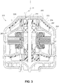
- Fig. 3 illustrates a blower 210 according to another embodiment of the present disclosure.
- the blower 210 is substantially similar to the blower 10 described above.
- the upper impeller 250 has a mixed flow configuration and corresponding portions of the first housing part 222 and first shield 260 are tapered to match the mixed flow configuration of the upper impeller 250.
- each of the blades 254 of the impeller includes an end portion 257 that tapers toward the outer edge.
- the end portion 257 of each blade 254 is bent, angled, or sloped downwardly with respect to the hub 258.
- a longitudinal axis L of each end portion 257 may be bent or angled at an angle ⁇ with respect to an axis H of the hub 258.
- angle ⁇ may be about 90°-160°, e.g., 125°.
- other suitable angles are possible depending on application.
- the upper wall 225 of the first housing part 222 is tapered to match the mixed flow configuration of the impeller 250, and the upper wall 267 of the shield 260 is tapered to match the mixed flow configuration of the impeller 250.
- Fig. 4 illustrates a blower 310 according to another embodiment of the present disclosure. Similar to the blowers 10, 210 described above, the blower 310 includes two stages with one impeller 350 positioned on one side of the motor 340 and one impeller 352 positioned on the other side of the motor 340. Also, the blower 310 has axial symmetry with both the inlet 326 and outlet 328 aligned with an axis 315 of the blower 310. In contrast, the blower 310 provides an alternative arrangement of the stationary portion.
- a stationary portion of the blower 310 includes a housing 320 with first and second housing parts 322, 324, a stator component 330 including stator vanes 332, and first and second shields 360, 370.
- a rotating portion of the blower 310 includes a rotatable shaft or rotor 380 adapted to be driven by motor 340 and first and second impellers 350, 352 provided to end portions of the shaft 380.
- the motor 340 includes a magnet 342 provided to shaft 380 and a stator assembly 344 to cause spinning movement of the shaft 380 via the magnet 342.
- the blower 310 may be relatively compact and have an overall diameter D of about 50-60 mm, e.g., 53 mm, and an overall length L of about 45-55 mm, e.g., 52 mm.
- Each impeller 350, 352 may have a diameter of about 40-45 mm, e.g., 42 mm.
- other suitable sizes are possible.
- the stator component 330 includes a base 334, an annular flange 336 extending from the base 334 to support the stator component 330 within the housing 320, a tube 338 to retain and align the bearings 300, 302 that rotatably support the shaft 380, and a plurality of stator vanes 332. Similar to the above embodiments, the stator component 330 may be integrally formed (e.g., injection molded) as a one-piece structure.
- each vane 332 includes an outer portion 339 that is sufficiently long so that it can support and maintain the stator assembly 344 in an operative position. As illustrated, the outer portion 339 of each vane 332 provides an interior surface 315 that engages an exterior surface 345 of the stator assembly 344.
- opposing vanes may define a diameter d of about 30-35 mm, e.g., 34 mm, for securing the stator assembly 344 in position.
- suitable sizes are possible, e.g., depending on the size of the stator assembly.
- each vane 332 is adapted to engage the shield 360 so that it can support and maintain the shield 360 in an operative position.
- the first or upper shield 360 includes an inner annular flange 367 and an outer annular flange 369.
- the inner annular flange 367 is structured to engage the upper end of the tube 338 of the stator component 330, e.g., with a friction fit
- the outer annular flange 369 is structured to engage the outer portion 339 of the vanes 332, e.g., with a friction fit.
- the second or lower shield 370 is supported and maintained by the second housing part 324 in an operative position.
- the hub 374 at the central portion of the shield 370 is shaped to direct the air flow down towards the outlet 328.
- the second housing part 324 of the housing 320 includes a plurality of stator vanes 325, e.g., between 2 and 100 (e.g., about 5-15)stator vanes, to direct airflow towards the outlet 328.
- the stator vanes 325 support the shield 370 within the second housing part 324 adjacent the outlet 328.
- at least one of the stator vanes 325 includes a projection 327 adapted to extend through an opening 377 provided in the shield 370 to align and secure the shield 370 in position.
- each of the blowers 10, 210, 310 described above may be supported within an outer casing or chassis (e.g., forming a portion of a NIVV device such as a PAP device or flow generator).
- each blower may be supported within the outer casing by a support system that is structured to provide support and provide a seal between the inlet and the outlet sides of the blower.
- the outer casing 400 includes a base 402 and a cover 404 provided to the base 402.
- the support system 405 includes a side 406 support and a bottom support 408 to support the blower (e.g., blower 10).
- the side support 406 is in the form of an annular ring (e.g., made of Silicone or TPE) that is provided to the blower housing (e.g., housing 20) and includes an end portion 407 adapted to engage within a respective slot 403 defined between the base 402 and cover 404.
- the bottom support 408 is in the form of multiple flexible feet or flexible pegs, e.g., 3 feet, that are adapted to engage the base wall of base 402.
- the annular ring 406 (also referred to as a divider seal or a soft girdle/seal) suspends/supports the blower 10 in the chassis and divides or seals the inlet side of the blower from the outlet side of the blower (i.e., divide or separate low and high pressure sides), e.g., to avoid the need for a connection tube that directs flow towards the outlet of the outer casing 400.
- the feet 408 may act as a backup seal between the inlet and outlet sides of the blower or a backup support for the blower, e.g., in case the ring 406 creeps in old age.
- a relatively small outlet muffler volume V1 is provided on the outlet side of the blower and a relatively small inlet muffler volume is provided on the inlet side of the blower V2.
- the annular ring 406 and feet 408 may be overmolded onto the outside of the first housing part 22 of the blower 10 (i.e., the first stage cover of the blower).
- an overmolded feeder 409 may interconnect the overmolded ring 406 with each of the overmolded feet 408.
- the first housing part 22 (along with the second housing part 24) may be constructed of a relatively rigid plastic material, e.g, polycarbonate (PC) or acrylonitrile butadiene styrene (ABS), and the overmolded ring 406, feet 408, and feeders 409 may be constructed of an elastomeric material, e.g., VersollanTM.
- the ring, feet, and/or feeders may be separate molded pieces that are attached in an operative position.
- the support system 405 provides an arrangement that avoids the need for inlet and outlet seals adjacent the inlet and outlet of the blower.
- the support system 405 is constructed of an elastomeric material that isolates (e.g., vibration isolated) and/or serves as a suspension between the blower 10 and the outer casing 400, e.g., without using springs.
- additional supports e.g., feet or pegs
- Each of the blowers 10, 210, 310 described above may include a sealing arrangement between the housing parts of the housing, e.g., to prevent leak or loss of pressure.
- the end portion of the first housing part 522 of the blower (i.e., the first stage cover of the blower) includes a stepped configuration with first and second steps 527(1), 527(2).
- Each of the steps 527(1), 527(2) is provided with a sealing structure, i.e., first and second seals 597(1), 597(2) respectively.
- the seals 597(1), 597(2) may be overmolded with the first housing part 522 in a manner as described above, e.g., elastomeric seals 597(1), 597(2) overmolded to relatively rigid plastic first housing part 522.
- the end portion of the second housing part 524 of the blower includes a similar stepped configuration as the first housing part 522, e.g., first and second steps 529(1), 529(2).
- the first seal 597(1) of the first housing part 522 engages the first step 529(1) of the second housing part 524 to provide a seal between housing parts 522, 524.
- the second step 527(2) of the first housing part 522 and the second step 529(2) of the second housing part 524 cooperate to define a slot adapted to receive and support the edge 531 of stator component 530 including stator vanes 532 (e.g., similar to stator component 30).
- the second seal 597(2) provides a seal between the stator component 530 and the housing parts 522, 524.
- multiple snap-fit members 516 are provided to the end portion of the first housing part 522 that are adapted to engage a respective shoulder 518 provided to the second housing part 524 with a snap-fit.
- the snap-fit members 516 secure the first and second housing parts 522, 524 to one another and maintain the seal.
- the first and second housing parts may be secured to one another in other suitable manners, e.g., welding, adhesive (e.g., gluing), heat staking, fasteners (e.g., screws), etc.
- Fig. 6-1 also illustrates an overmolded ring 406 and feeder 409 provided to the first housing part 522, and the ring 406 engaged within the slot between the base 402 and cover 404 of an outer casing as described above.
- Fig. 6-1 illustrates impeller 554 between stator component 530 and the outlet of the blower.
- the edge 531 of the stator component 530 may include a relatively rigid protrusion 533 (e.g., v-shaped protrusion) adapted to engage the second seal 597(2), e.g., to improve grip and sealing.
- the second seal 597(2) may have a more block-like configuration, rather than a bead-like configuration as shown in Fig. 6-1 .
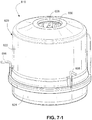
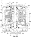
- Figs. 7-1 to 7-13 illustrate a blower 610 according to another embodiment of the present disclosure. Similar to the blowers 10, 210, 310 described above, the blower 610 includes two stages with one impeller 650 positioned on one side of the motor 640 and one impeller 652 positioned on the other side of the motor 640. Also, the blower 610 has axial symmetry with both the inlet 626 and outlet 628 aligned with an axis 615 of the blower 610.
- a stationary portion of the blower 610 includes a housing 620 with first and second housing parts 622, 624, a stator component 630, and first and second shields 660, 670.
- a rotating portion of the blower 610 includes a rotatable shaft or rotor 680 adapted to be driven by motor 640 and first and second impellers 650, 652 (e.g., mixed flow) provided to end portions of the shaft 680.
- the motor 640 includes a magnet 642 provided to shaft 680 and a stator assembly 644 to cause spinning movement of the shaft 680 via the magnet 642.
- the stator assembly 644 includes windings 646 and a stator or stator lamination stack 648 (e.g., slotless or toothless) provided to the windings 646.
- the resistance of the windings 646 and/or current draw may be monitored to determine temperature, which may be used to indicate faults in the motor (e.g., bearing fault detection, bearing end of life failure or rubbing condition, software fault in the electronic drive systems). For example, after the motor has stopped but still remains warm, the resistance of the windings may be measured (e.g., via a circuit in the blower). It is noted that resistance of the windings changes with temperature in a known way.
- the device would go into a fault mode, e.g., and prompt the user to have the blower serviced.
- a fault mode e.g., and prompt the user to have the blower serviced.
- blower faults tend to lead to unusually high temperatures, e.g., bearing end of life failures or software faults in electronic drive systems.
- the inlet 626 is provided by the first housing part 622 (also referred to as a first stage cover) at one end and the outlet 628 is provided by the second housing part 624 (also referred to as a final stage cover) at the other end.
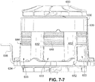
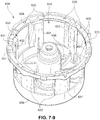
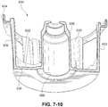
- the stator component 630 includes an annular base portion 634, a shield portion 636, a tube or bearing tube 638 extending from the shield portion 636, and a plurality of spaced apart side walls 632 extending between the base portion 634 and the shield portion 636. As illustrated, the stator component 630 forms a cylindrical "cage" and the spaced apart side walls 632 define openings 633 into the "cage".
- the stator component 630 may be integrally formed (e.g., injection molded) as a one-piece structure. However, the stator component 630 may be constructed in other suitable manners and/or may be made in separate parts.
- the base portion 634 is sandwiched between the first and second housing parts 622, 624 to support the stator component 630 within the housing 620.
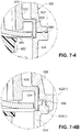
- the second housing part 624 may include a protrusion 695 (e.g., v-shaped protrusion as best shown in Fig. 7-4 ) adapted to engage the first housing part 622, e.g., to improve grip and sealing.
- the first housing part 622 may include a connecting portion 622(1) structured to overlap and/or overhang a connecting portion 624(1) of the second housing part 624. Similar to the above embodiment, the base portion 634 of the stator component 630 is sandwiched between the first and second housing parts 622, 624. In addition, the second housing part 624 may include a protrusion 696 for sealing against the first housing part 622.
- the outer edge of the shield portion 636 substantially aligns with or extends radially beyond the outer edge of the impeller 650.
- the shield portion 636 provides a narrow annular gap 710 between its outer edge and the side wall of the housing part 622, which is sufficient to direct gas into the stator component 630.
- the shield portion 636 includes an opening 666 that allows access to the interior of the tube 638.
- the tube 638 is structured to retain and align bearings 600, 602 (e.g., of mixed bearing sizes) that rotatably support the shaft 680.
- the tube 638 is sufficiently “magnetically transparent", which allows the stator assembly 644 to act on the magnet 642 positioned within the tube 638 without significant loss of flux density and/or increased heat, if any.
- the tube 638 may be constructed of an acoustically damped material to damp vibrations caused by rotor operation, e.g., polypropylene, nylon (reinforced), liquid crystal polymer (LCP) with ceramic loading (conduct heat), polyphenylene sulfide (PPS) with graphite fill, polyetheretherketone (PEEK). If ball bearings are utilized, the number of balls within the bearings may be optimized to minimize vibrations.
- an acoustically damped material to damp vibrations caused by rotor operation e.g., polypropylene, nylon (reinforced), liquid crystal polymer (LCP) with ceramic loading (conduct heat), polyphenylene sulfide (PPS) with graphite fill, polyetheretherketone (PEEK).
- LCP liquid crystal polymer
- PPS polyphenylene sulfide
- PEEK polyetheretherketone
- a cap portion 668 is provided to the shield portion 636 along the opening 666.
- the cap portion 668 provides a stop for the bearing 600 and hence retains the shaft 680 within the tube 638.
- the cap portion 668 may act as a spacer for the impeller 650.
- Washers 604 and a spring or biasing element 606 may be provided between the bearing 602 and the rotor magnet 642 and a spacer 607 may be provided between the bearing 600 and the rotor magnet 642, e.g., to maintain alignment/spacing of the rotor magnet 642 with the stator assembly 644, act as wear stop, and/or provide a pre-load.
- the spacer 607 e.g., constructed of metallic ferrite
- adjacent the bearing 600 acts as a magnetic shunt or flux shield to direct magnetic field towards the windings 646 and away from the bearing 600, e.g., to avoid heating bearing. It should be appreciated that such a spacer or shield may also be provided adjacent the bearing 602.
- the flux shield may be an optional component, but may increase bearing/lube life due to reduced eddy current losses in the bearing outer races and balls.
- the spring 606 provides an inner race pre-load (IRP), e.g., about 1.25 lb spring load, on the bearing 602.
- IRP inner race pre-load
- the bearing 602 includes an inner race 602(1), an outer race 602(2), and ball bearings 602(3) provided between the inner and outer races (e.g., there may be a clearance between the ball bearings and the races).
- the inner and outer races 602(1), 602(2) provide surfaces upon which the ball bearings 602(3) run.
- the bearing may include a spacer element between the inner and outer races to maintain spacing between the ball bearings (e.g., cylinder with openings to receive respective ball bearings).
- the spring 606 is constructed and arranged to engage the inner race 602(1) of the bearing 602 to provide a spring load to the bearing, which brings the ball bearings into contact with the races (i.e., load transmitted from the inner race to the ball bearings, and from the ball bearings to the outer race).
- the spring may be constructed and arranged to provide an outer race pre-load (ORP) on the bearing, e.g., see Figs. 8 and 9-1 to 9-2 described below.
- ORP outer race pre-load
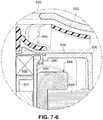
- the shield portion 636 and cap portion 668 cooperate to provide by-pass passages or conduits 686 (as shown in Figs. 7-6 and 7-8) to provide pressure balance across the bearings 600, 602.
- the by-pass passages 686 provide a short circuit of pressure around the tube 638 and hence the bearings 600, 602.
- a tight tolerance i.e., a small gap
- air can flow with less resistance through the by-pass passage or bleed hole 686 (e.g., tight tolerance may also apply to the by-pass arrangement shown in Fig. 1-1 ).
- the stator assembly 644 is provided along the exterior surface of the tube 638.
- the stator component 630 and first shield 660 cooperate to support and maintain the stator assembly 644 in an operative position, as described in greater detail below.
- the first shield 660 includes a base 661 and a plurality of stator vanes 663 provided to the base 661.
- the first shield 660 is attached to the stator component 630, e.g., by engaging pins 665 on the first shield 660 with respective openings 635 provided in the base portion 634 of the stator component 630 (e.g., pins heat staked into position).
- the first shield 660 may be attached to the stator component 630 in other suitable manners.
- the plurality of stator vanes 663 are structured to direct airflow towards an orifice 667 in the base 661.
- the stator component 630 has six stator vanes 663.
- Each vane 663 is substantially identical and has a generally spiral shape.
- each vane 663 includes an inner portion 637 (adjacent the orifice 667) and an outer portion 639. As best shown in Fig. 7-11 , the inner portion 637 is recessed (e.g., reduced in height) with respect to the outer portion 639.
- the windings 646 of the stator assembly 644 are engaged or supported by the recessed, inner portion 637 of the stator vanes 663, and the stack 648 of the stator assembly 644 is engaged or supported by the outer portion 639 of the stator vanes 663.
- the exterior surface 649 of the stack 648 (e.g., see Figs. 7-3 and 7-5 ) includes a toothed configuration that is adapted to engage or interlock with spaced-apart teeth 651 provided by interior surfaces of the spaced apart side walls 632 (e.g., see Fig. 7-9 ). Remaining portions of the toothed configuration of the stack 648 at least partially protrude through the openings 633 in the stator component 630, e.g., flush with exterior surfaces of the side walls 632 (see Figs. 7-5 and 7-7 ). Thus, the stator component 630 and first shield 660 cooperate to retain or secure the stator assembly 644 in an operative position.
- wires 698 extend from the windings 646 to outside the housing 620 to conduct current from an external source to the windings 646.
- slots 631 are provided through the stator component 630 (see Fig. 7-9 ) and slots 621 are provided through the housing 620 (see Fig. 7-3 ) to accommodate passage of respective wires 698 from the windings 646 to outside the housing 620.
- the stack 648 and windings 646 are exposed to the flow of gas, e.g., via the openings 633 in the stator component 630, as shown in Figs. 7-3 , 7-5 , and 7-7 .
- This arrangement allows forced-convection cooling of the stack 648/windings 646 as gas flows through the stator component 630 in use. In addition, this arrangement may assist in heating the patient air.
- the second shield 670 includes a plurality of stator vanes 672, e.g., between 2 and 100 stator vanes, to direct airflow towards the outlet 628.
- the shield 670 has 7 stator vanes.
- Each vane 672 is substantially identical and has a generally spiral shape.
- each vane 672 includes an inner portion 673 (adjacent the hub 674) and an outer portion 675.
- the outer portion 675 is recessed (e.g., reduced in height) with respect to the inner portion 673, and a contoured edge 676 extends between the inner and outer portions 673, 675.
- stator vanes 672 support the shield 670 within the second housing part 624 adjacent the outlet 628.
- the contoured edge 676 of the shield 670 engages the edge of the outlet 628 to align the shield 670 with the outlet 628 (see Fig. 7-3 ).
- the hub 674 and inner portion 673 of the vanes 672 extend at least partially through the outlet 628 and the outer portion 675 of the vanes 672 engage the lower wall of the second housing part 624, as best shown in Fig. 7-3 .
- the hub 674 at the central portion of the shield 670 is shaped to direct the air flow down towards the outlet 628.
- the second shield 670 includes pins 677 that are adapted to engage with respective openings 678 provided in lower wall of the second housing part 624, e.g., pins heat staked into position, as shown in Fig. 7-3 .
- the second shield 670 may be attached to the second housing part 624 in other suitable manners.
- the second shield 670 (also referred to as a final stage disc) includes a disc or shield to cover the stator vanes 672 in order to keep any discontinuities away from the blades of the impeller 652.
- the stator vanes 672 may be integrated into the second housing part 624, and the impeller 652 may include a lower shroud to act as a rotating shroud or shield between the impeller blades and stator vanes 672.
- air passes into the second impeller 652 where it is accelerated tangentially and directed radially outward. Air then flows in a spiral manner with a large tangential velocity component and also an axial component passing through the gap 712 defined by the outer edge of the second shield 670 and the side wall of housing part 624. Air then enters the stator vanes 672 formed in the shield 670 and is directed towards the outlet 628.
- the blowers include stator vanes to direct airflow towards a second stage and towards the outlet.
- Such stator vanes help to straighten the flow and remove the "swirl" caused by the impellers.
- the stator vanes may be replaced with alternative structure to direct or straighten flow.
- a grid, mesh (e.g., woven), honeycomb-like structure, and/or extrusion (e.g., helical) may be provided to direct flow in use.
- multiple tangential feeds may be provided to the axial outlet 628 to direct flow tangentially from the outlet.
- the tube of the stator component is used as a mandrel to help form the windings of the stator assembly.
- the tube is structured and shaped to facilitate its use as a mandrel.
- the cylindrical and tapered construction of the tube facilitates its use as a mandrel.
- the shape may be polygonal, e.g., rectangle, triangle, square, pentagon, hexagon, etc.
- the tube may include one or more structural components, such as splines, to aid with separation of the windings from the mandrel.
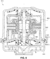
- Fig. 8 illustrates a blower according to another embodiment of the present disclosure.
- the blower is similar to blower 610 described above and indicated with similar reference numerals.
- the first shield 660 i.e., the interstage "de-swirl" vane
- the first shield 660 includes a lip region or flange 660(1) adapted to engage or seal against the second housing part 624.
- the lip region 660(1) of the first shield 660 is structured to engage the base portion 634 of the stator component 630, and the lip region 660(1) and base portion 634 are supported and/or sandwiched between the first and second housing parts 622, 624 to support the first shield 660 and the stator component 630 within the housing 620.
- the lip region/base portion arrangement is structured to provide an interstage seal to prevent air leakage from the second stage back into the first stage in use.
- the connecting portion 622(1)of the first housing part 622 is structured to overlap and/or overhang the connecting portion 624(1) of the second housing part 624.
- an interstage seal may be provided in other suitable manners.
- a gasket or gooey sealant may be used at the interfaces of the shield 660, stator component 630, and housing parts 622, 624.
- one or more of the interface surfaces may be overmolded with a soft silicone or TPE.
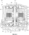
- Figs. 9-1 to 9-2 illustrate a blower 810 according to another embodiment of the present disclosure. Similar to the blowers described above, the blower 810 includes two stages with one impeller 850 positioned on one side of the motor 840 and one impeller 852 positioned on the other side of the motor 840. Also, the blower 810 has axial symmetry with both the inlet 826 and outlet 828 aligned with an axis 815 of the blower 810.
- the bearings 800, 802 that support shaft 880 are retained by a metal housing assembly (rather than a plastic tube), as described in greater detail below.
- the metal housing assembly includes a "cage"-like adaptor that supports the metal housing assembly within the blower housing and allows gas to flow into the first shield and onto the second stage in a similar manner to the "cage" like stator component described above.
- a stationary portion of the blower 810 includes a housing 820 with first and second housing parts 822, 824, a metal housing assembly 830, and first and second shields 860, 870.
- a rotating portion of the blower 810 includes a rotatable shaft or rotor 880 adapted to be driven by motor 840 and first and second impellers 850, 852 provided to end portions of the shaft 880.
- the motor 840 includes a magnet 842 provided to shaft 880 and a stator assembly 844 to cause spinning movement of the shaft 880 via the magnet 842.
- the housing assembly 830 is constructed of a metallic material and includes a main housing 832, an end bell 834, and an adaptor 836 (e.g., secured to one another by one or more fasteners 838).
- the main housing 832 provides a recess for supporting bearing 800
- the end bell 834 provides a recess for supporting bearing 802.
- the main housing and end bell are structured to support bearings of the same size. However, the main housing and end bell may be structured to support mixed bearing sizes.
- the metal bearing support provided by the housing assembly 830 improves heat transfer from the bearings in use.
- the main housing 832, end bell 834, and adaptor 836 e.g., constructed of aluminum
- the end bell and adaptor may be aluminum die cast pieces for high volume production.
- the adaptor 836 forms a cylindrical "cage" that defines openings 833 into the cage.
- the main housing 832 and end bell 834 cooperate to support and maintain the stator assembly 844 in an operative position.
- a lip region 860(1) of the first shield 860 is structured to engage the base 836(1) of the adaptor 836, and the lip region 860(1) and base 836(1) are supported and/or sandwiched between the first and second housing parts 822, 824 to support the first shield 860 and housing assembly 830 within the housing 820.
- the lip region/base arrangement is structured to provide an interstage seal to prevent air leakage from the second stage back into the first stage in use.
- a spacer or flux shield 804 is provided between each bearing 800, 802 and the rotor magnet 842.
- a spring or biasing element 806 is provided between the bearing 802 and the end cap 834.
- the spring 806 (e.g., crest-to-crest spring) provides an outer race preload (ORP) (outer race preload also shown in Fig. 8 ) on the bearing 802 (instead of an inner race preload such as that shown in Fig. 7-3 ).
- ORP outer race preload
- the spring 806 is constructed and arranged to engage the outer race 802(2) of the bearing 802 to provide a spring load to the bearing, which brings the ball bearings into contact with the races (i.e., load transmitted from the outer race 802(2) to the ball bearings 802(3), and from the ball bearings 802(3) to the inner race 802(1)).
- the ORP arrangement may reduce or eliminate corrosion of the second stage bearing 802 (e.g., at the inner race) over the life of the blower.
- air passes into the second impeller 852 where it is accelerated tangentially and directed radially outward. Air then flows in a spiral manner with a large tangential velocity component and also an axial component passing through the gap 912 defined by the outer edge of the second shield 870 and the side wall of housing part 824. Air then enters the stator vanes 872 formed in the shield 870 and is directed towards the outlet 828.
- Figs. 10-1 to 10-3 illustrate a stator 948 for a stator assembly according to an embodiment of the present disclosure.
- the stator 948 includes an outer portion 948(1) ( Fig. 10-1 ) and an inner portion 948(2) ( Fig. 10-2 ) structured to be received within the outer portion 948(1).
- Fig. 10-3 shows the stator 948 with the assembled outer and inner portions 948(1), 948(2).
- the inner portion 948(2) has a plurality of stator teeth 949, e.g., six stator teeth, on which stator coils or windings are wound.
- the outer portion 948(1) is ring shaped and includes a plurality of recesses 950 along its inner circumference adapted to receive respective teeth of the inner portion 948(2). When assembled, the stator 948 provides a closed slot arrangement.
- the outer circumference of the outer portion 948(1) includes a toothed configuration that is adapted to engage or interlock with the stator component (e.g. for use in blower 610 similar to the arrangement described above in relation to Figs. 7-7 and 7-9 ).
- one or more slots 951 may be provided in the outer circumference of the outer portion 948(1) to accommodate passage of respective wires from the windings.
- This "closed-slot" stator-core arrangement facilitates the insertion of magnet wire because magnet wire can be inserted from the outside via a generously wide slot opening. That opening becomes closed when the outer portion 948(1) is provided to the toothed inner portion 948(2). In its final assembled form, there is no opening of the slot, and as such, there is little magnetic detent (or magnetic cogging effect) produced by the interaction of the rotor's salient poles and the stator. It is a cost-effective, low cogging configuration.
- each tooth 949 of the inner portion 948(2) has a generally T-shaped arrangement with substantially square edges.
- the end portion of each tooth 949 (and corresponding recesses 950 in the outer portion 948(1)) may be more rounded.
- the stator assembly may include an ironless and slotless stator (i.e., using air as the flux return path, rather than using iron to concentrate the flux).
- an ironless and slotless stator i.e., using air as the flux return path, rather than using iron to concentrate the flux.
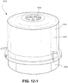
- Figs. 12-1 to 12-3 illustrate a blower 1010 according to another embodiment of the present disclosure. Similar to the blowers described above, the blower 1010 includes two stages with one impeller 1050 positioned on one side of the motor 1040 and one impeller 1052 positioned on the other side of the motor 1040. Also, the blower 1010 has axial symmetry with both the inlet 1026 and outlet 1028 aligned with an axis of the blower 1010.
- the stator 1048 of the stator assembly includes a slotted configuration.
- the stator or lamination stack 1048 includes a ringshaped main body 1048(1) and a plurality of stator teeth 1048(2), e.g., six stator teeth, extending radially inwardly from the main body 1048(1).
- the stator coils or windings 1046 are wound on respective teeth 1048(2) as shown in Fig. 12-2 .
- the windings can be inserted from the inside via respective slot openings (spacing between teeth).
- the outer circumference of the main body 1048(1) includes a toothed configuration that is adapted to engage or interlock with the stator component 1030.
- one or more slots 1051 may be provided in the outer circumference of the main body 1048(1) to accommodate passage of respective wires from the windings 1046.
- blower The remaining portions of the blower are similar to arrangements described above, e.g., housing 1020 with first and second housing parts 1022, 1024, "cage"-like stator component 1030 with bearing tube 1038, and first and second shields 1060, 1070.
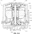
- Figs. 13-1 to 13-2 illustrate a blower 1110 according to another embodiment of the present disclosure. Similar to the blowers described above, the blower 1110 includes two stages with one impeller 1150 positioned on one side of the motor 1140 and one impeller 1152 positioned on the other side of the motor 1140. Also, the blower 1110 has axial symmetry with both the inlet 1126 and outlet 1128 aligned with an axis of the blower 1110.
- the blower 1110 includes a coreless motor in which the windings or magnet wire are wound directly on the stator component thereby eliminating a stator or lamination stack.
- windings or magnet wire 1146 may be wound directly on the bearing tube 1138 of the stator component 1130.
- the windings may be at least partially supported by side walls of the stator component.
- the remaining portions of the blower are similar to arrangements described above, e.g., housing 1120 with first and second housing parts 1122, 1124, "cage"-like stator component 1130, and first and second shields 1160, 1170.
- the first housing part 1122 may include one or more guide structures 1123 for guiding magnet wire outside the housing, e.g., binding post for looping wire.
- the bearings supporting the shaft may be bonded to respective ends of the bearing tube by a plasma treatment stage.
- plasma may be used to treat the plastic surface of the first stage bearing seat of bearing tube 638 that engages the outer race of bearing 600.
- the plasma treatment allows the adhesive of choice (e.g., a Loctite cyanoacrylate compound) to wet nicely when applied. This wetting action has been shown to increase the bondline strength and also reduce the variation in that process (as determined by shear strength).
- the bondline holds the rotor assembly within the tube and stator assembly.
- liquid primers may be used to treat the bearing seat before the adhesive (e.g., a Loctite cyanoacrylate compound) is applied.
- an alternative to cyanoacrylate compound as an adhesive with the plasma/primers may be epoxy.
- first and second housing parts of the housing may be bonded together with ultrasonic welding using a shear joint.
- combinations of rigid and softer materials may be molded in a two-shot process (e.g., co-molding) to improve sealing in various positions through the blower.
- a "binding post" or “cleat” may be positioned on the outside of the housing.
- One or more wires may be looped around that binding post so that the lengths of the wires can be equalized.
- a labyrinth seal may be provided to allow the pressure to equalize between the outboard side of the first-stage bearing and the outboard side of the second-stage bearing to the extent that it is possible with minimal recirculating flow beneath the first-stage impeller (e.g., see Figs. 7-3 and 7-6 ).
Landscapes
- Engineering & Computer Science (AREA)
- Power Engineering (AREA)
- Mechanical Engineering (AREA)
- General Engineering & Computer Science (AREA)
- Health & Medical Sciences (AREA)
- Emergency Medicine (AREA)
- Pulmonology (AREA)
- Anesthesiology (AREA)
- Biomedical Technology (AREA)
- Heart & Thoracic Surgery (AREA)
- Hematology (AREA)
- Life Sciences & Earth Sciences (AREA)
- Animal Behavior & Ethology (AREA)
- General Health & Medical Sciences (AREA)
- Public Health (AREA)
- Veterinary Medicine (AREA)
- Physics & Mathematics (AREA)
- Thermal Sciences (AREA)
- Structures Of Non-Positive Displacement Pumps (AREA)
- Manufacture Of Motors, Generators (AREA)
Claims (3)
- Procédé de formation d'enroulements d'un ensemble stator dans une soufflante (610), comprenant :la fourniture d'une partie fixe pour la soufflante (610) incluant un tube (638) adapté pour supporter un rotor (680) ; etl'utilisation du tube (638) en tant que mandrin pour former les enroulements (646) de l'ensemble stator (644),la mise en forme du tube (638) pour faciliter son utilisation en tant que mandrin, et la mise en forme du tube (638) pour inclure une construction cylindrique et effilée.
- Procédé selon la revendication 1, comprenant en outre la fourniture au tube (638) d'un ou de plusieurs composants structurels pour faciliter la séparation des enroulements (646) du tube (638).
- Procédé selon l'une quelconque des revendications précédentes, comprenant en outre la fourniture au tube d'une ou de plusieurs cannelures.
Priority Applications (1)
| Application Number | Priority Date | Filing Date | Title |
|---|---|---|---|
| EP21190430.5A EP3978761B1 (fr) | 2007-06-05 | 2008-06-05 | Dispositif de pression positive des voies aériennes |
Applications Claiming Priority (4)
| Application Number | Priority Date | Filing Date | Title |
|---|---|---|---|
| US92490907P | 2007-06-05 | 2007-06-05 | |
| US99600107P | 2007-10-24 | 2007-10-24 | |
| US6447708P | 2008-03-07 | 2008-03-07 | |
| EP08157685.2A EP2000675B1 (fr) | 2007-06-05 | 2008-06-05 | Système de paliers pour ventilateur |
Related Parent Applications (1)
| Application Number | Title | Priority Date | Filing Date |
|---|---|---|---|
| EP08157685.2A Division EP2000675B1 (fr) | 2007-06-05 | 2008-06-05 | Système de paliers pour ventilateur |
Related Child Applications (1)
| Application Number | Title | Priority Date | Filing Date |
|---|---|---|---|
| EP21190430.5A Division EP3978761B1 (fr) | 2007-06-05 | 2008-06-05 | Dispositif de pression positive des voies aériennes |
Publications (2)
| Publication Number | Publication Date |
|---|---|
| EP3480471A1 EP3480471A1 (fr) | 2019-05-08 |
| EP3480471B1 true EP3480471B1 (fr) | 2021-08-11 |
Family
ID=39527926
Family Applications (3)
| Application Number | Title | Priority Date | Filing Date |
|---|---|---|---|
| EP08157685.2A Not-in-force EP2000675B1 (fr) | 2007-06-05 | 2008-06-05 | Système de paliers pour ventilateur |
| EP21190430.5A Active EP3978761B1 (fr) | 2007-06-05 | 2008-06-05 | Dispositif de pression positive des voies aériennes |
| EP18206950.0A Active EP3480471B1 (fr) | 2007-06-05 | 2008-06-05 | Ventilateur avec tube support |
Family Applications Before (2)
| Application Number | Title | Priority Date | Filing Date |
|---|---|---|---|
| EP08157685.2A Not-in-force EP2000675B1 (fr) | 2007-06-05 | 2008-06-05 | Système de paliers pour ventilateur |
| EP21190430.5A Active EP3978761B1 (fr) | 2007-06-05 | 2008-06-05 | Dispositif de pression positive des voies aériennes |
Country Status (6)
| Country | Link |
|---|---|
| US (4) | US8636479B2 (fr) |
| EP (3) | EP2000675B1 (fr) |
| JP (7) | JP5468747B2 (fr) |
| CN (5) | CN101324238B (fr) |
| AU (1) | AU2008202487B2 (fr) |
| NZ (3) | NZ579429A (fr) |
Families Citing this family (404)
| Publication number | Priority date | Publication date | Assignee | Title |
|---|---|---|---|---|
| JP2007506482A (ja) | 2003-09-25 | 2007-03-22 | レスメド リミテッド | 呼吸器マスクおよびシステム |
| PL1719916T3 (pl) * | 2005-05-07 | 2009-01-30 | Grundfos Management As | Agregat pompowy |
| WO2008028247A1 (fr) | 2006-09-07 | 2008-03-13 | Resmed Ltd | Masque et système générateur de flux |
| NZ603342A (en) * | 2006-10-24 | 2014-08-29 | Resmed Motor Technologies Inc | Vibration isolation system for a respiratory treatment device |
| AU2013222004B2 (en) * | 2006-10-24 | 2015-12-24 | Resmed Motor Technologies Inc. | Brushless DC Motor with Bearings |
| JP5468747B2 (ja) * | 2007-06-05 | 2014-04-09 | レスメド・モーター・テクノロジーズ・インコーポレーテッド | 軸受管を有するブロワ |
| GB2452593A (en) | 2007-09-04 | 2009-03-11 | Dyson Technology Ltd | A fan |
| US8137082B2 (en) * | 2007-12-20 | 2012-03-20 | G-G Distribution And Development Co., Inc. | Air blower assembly |
| AU2009200357B2 (en) * | 2008-01-31 | 2013-10-24 | ResMed Pty Ltd | Respiratory Apparatus |
| GB2463698B (en) | 2008-09-23 | 2010-12-01 | Dyson Technology Ltd | A fan |
| GB2464736A (en) | 2008-10-25 | 2010-04-28 | Dyson Technology Ltd | Fan with a filter |
| US8453640B2 (en) | 2008-11-12 | 2013-06-04 | Resmed Limited | Positive airway pressure device |
| GB2466058B (en) | 2008-12-11 | 2010-12-22 | Dyson Technology Ltd | Fan nozzle with spacers |
| WO2010080709A1 (fr) | 2009-01-08 | 2010-07-15 | Hancock Medical | Systèmes de pression des voies respiratoires positifs intermittents et autonomes, et méthodes de traitement de l'apnée du sommeil, du ronflement et d'autres troubles respiratoires |
| GB2467965B (en) * | 2009-02-24 | 2015-04-22 | Dyson Technology Ltd | Rotor assembly |
| GB2467966B (en) * | 2009-02-24 | 2013-04-03 | Dyson Technology Ltd | Rotor assembly |
| JP5218637B2 (ja) * | 2009-02-24 | 2013-06-26 | パナソニック株式会社 | ガスレーザ発振装置およびガスレーザ加工機 |
| GB2468329A (en) | 2009-03-04 | 2010-09-08 | Dyson Technology Ltd | Fan assembly |
| GB2468323A (en) | 2009-03-04 | 2010-09-08 | Dyson Technology Ltd | Fan assembly |
| KR101370271B1 (ko) | 2009-03-04 | 2014-03-04 | 다이슨 테크놀러지 리미티드 | 선풍기 |
| GB2468331B (en) * | 2009-03-04 | 2011-02-16 | Dyson Technology Ltd | A fan |
| GB0903682D0 (en) | 2009-03-04 | 2009-04-15 | Dyson Technology Ltd | A fan |
| EP2414738B1 (fr) | 2009-03-04 | 2013-10-09 | Dyson Technology Limited | Appareil humidificateur |
| GB2476171B (en) | 2009-03-04 | 2011-09-07 | Dyson Technology Ltd | Tilting fan stand |
| GB2468326A (en) | 2009-03-04 | 2010-09-08 | Dyson Technology Ltd | Telescopic pedestal fan |
| CA2746496C (fr) | 2009-03-04 | 2012-12-04 | Dyson Technology Limited | Ensemble de ventilateur |
| GB2468317A (en) | 2009-03-04 | 2010-09-08 | Dyson Technology Ltd | Height adjustable and oscillating fan |
| AU2010219495B2 (en) | 2009-03-04 | 2011-11-10 | Dyson Technology Limited | A fan |
| GB2468320C (en) * | 2009-03-04 | 2011-06-01 | Dyson Technology Ltd | Tilting fan |
| GB2468315A (en) | 2009-03-04 | 2010-09-08 | Dyson Technology Ltd | Tilting fan |
| GB2468312A (en) | 2009-03-04 | 2010-09-08 | Dyson Technology Ltd | Fan assembly |
| US10238822B2 (en) | 2009-05-29 | 2019-03-26 | Resmed Limited | PAP system |
| CN101567589B (zh) * | 2009-06-01 | 2011-12-28 | 深圳市大族电机科技有限公司 | 振镜电机 |
| US8931481B2 (en) * | 2009-06-04 | 2015-01-13 | Redmed Limited | Flow generator chassis assembly with suspension seal |
| DE102009028196A1 (de) * | 2009-08-04 | 2011-02-10 | Robert Bosch Gmbh | Luftspulenwicklung für HVAC-Gebläse |
| NZ597256A (en) * | 2009-08-11 | 2013-11-29 | Resmed Motor Technologies Inc | Single stage, axial symmetric blower and portable ventilator |
| NZ706289A (en) | 2009-08-28 | 2016-09-30 | Resmed Ltd | Pap system |
| EP2496297B1 (fr) | 2009-11-03 | 2020-09-16 | ResMed Pty Ltd | Systèmes de ventilation spontanée en pression positive continue |
| GB0919473D0 (en) | 2009-11-06 | 2009-12-23 | Dyson Technology Ltd | A fan |
| WO2011062633A1 (fr) | 2009-11-19 | 2011-05-26 | Resmed Motor Technologies, Inc. | Soufflerie |
| FR2953142B1 (fr) * | 2009-12-02 | 2013-04-12 | Airfan | Appareil de delivrance regulee d'un gaz,notamment appareil d'assistance respiratoire |
| US8496448B2 (en) * | 2010-03-16 | 2013-07-30 | Toyota Motor Engineering & Manufacturing North America, Inc. | Pump assembly |
| GB2478925A (en) | 2010-03-23 | 2011-09-28 | Dyson Technology Ltd | External filter for a fan |
| GB2478927B (en) | 2010-03-23 | 2016-09-14 | Dyson Technology Ltd | Portable fan with filter unit |
| US9358409B2 (en) * | 2010-04-06 | 2016-06-07 | 3M Innovative Properties Company | Air filtration device |
| ES2553148T3 (es) | 2010-05-27 | 2015-12-04 | Dyson Technology Limited | Dispositivo de soplado de aire por medio de un conjunto de tobera de rendija estrecha |
| GB2482549A (en) | 2010-08-06 | 2012-02-08 | Dyson Technology Ltd | A fan assembly with a heater |
| GB2482548A (en) | 2010-08-06 | 2012-02-08 | Dyson Technology Ltd | A fan assembly with a heater |
| GB2482547A (en) | 2010-08-06 | 2012-02-08 | Dyson Technology Ltd | A fan assembly with a heater |
| CN101949389B (zh) * | 2010-08-27 | 2011-12-14 | 梁雪华 | 用于抽风机的伸缩盘 |
| GB2483448B (en) * | 2010-09-07 | 2015-12-02 | Dyson Technology Ltd | A fan |
| US10100836B2 (en) | 2010-10-13 | 2018-10-16 | Dyson Technology Limited | Fan assembly |
| WO2012052735A1 (fr) | 2010-10-18 | 2012-04-26 | Dyson Technology Limited | Ensemble ventilateur |
| GB2484670B (en) | 2010-10-18 | 2018-04-25 | Dyson Technology Ltd | A fan assembly |
| JP5778293B2 (ja) | 2010-11-02 | 2015-09-16 | ダイソン テクノロジー リミテッド | 送風機アセンブリ |
| GB2486019B (en) | 2010-12-02 | 2013-02-20 | Dyson Technology Ltd | A fan |
| US20120171024A1 (en) * | 2011-01-02 | 2012-07-05 | Asia Vital Components Co., Ltd. | Bearing holding structure and fan module using same |
| US8327846B2 (en) | 2011-02-08 | 2012-12-11 | Hancock Medical, Inc. | Positive airway pressure system with head position control |
| AU2012220358B2 (en) * | 2011-02-25 | 2014-11-06 | Resmed Motor Technologies Inc. | Blower and PAP system |
| CN118490942A (zh) * | 2011-04-18 | 2024-08-16 | 瑞思迈发动机及马达技术股份有限公司 | Pap系统鼓风机 |
| JP2012241755A (ja) * | 2011-05-17 | 2012-12-10 | Honda Motor Co Ltd | 回転電機のハウジング |
| US10137264B2 (en) | 2011-07-13 | 2018-11-27 | Fisher & Paykel Healthcare Limited | Respiratory assistance apparatus |
| CA2840594C (fr) | 2011-07-13 | 2020-03-10 | Fisher & Paykel Healthcare Limited | Ensemble rotor et moteur |
| AU2012288597B2 (en) | 2011-07-27 | 2015-04-09 | Dyson Technology Limited | A fan assembly |
| GB2493506B (en) | 2011-07-27 | 2013-09-11 | Dyson Technology Ltd | A fan assembly |
| CN115405569A (zh) | 2011-08-05 | 2022-11-29 | 瑞思迈发动机及马达技术股份有限公司 | 鼓风机 |
| GB2493974B (en) | 2011-08-26 | 2014-01-15 | Dyson Technology Ltd | Bearing assembly |
| KR101285223B1 (ko) * | 2011-09-08 | 2013-07-11 | 연세대학교 산학협력단 | 물 플라즈마를 이용한 금속 분말 점화방법, 소형 연소장치 및 연소방법 |
| DE102011112817A1 (de) * | 2011-09-12 | 2013-03-14 | Brose Fahrzeugteile GmbH & Co. Kommanditgesellschaft, Würzburg | Elektromotor, insbesondere Kühlerlüftermotor |
| WO2013069153A1 (fr) * | 2011-11-11 | 2013-05-16 | 三菱電機株式会社 | Machine électrique tournante pour véhicule |
| GB201119500D0 (en) | 2011-11-11 | 2011-12-21 | Dyson Technology Ltd | A fan assembly |
| GB2496877B (en) | 2011-11-24 | 2014-05-07 | Dyson Technology Ltd | A fan assembly |
| GB2498547B (en) | 2012-01-19 | 2015-02-18 | Dyson Technology Ltd | A fan |
| CN104093990A (zh) * | 2012-02-02 | 2014-10-08 | 爱赛特股份公司 | 用于呼吸器的隔音壳体 |
| GB2499044B (en) | 2012-02-06 | 2014-03-19 | Dyson Technology Ltd | A fan |
| GB2499042A (en) | 2012-02-06 | 2013-08-07 | Dyson Technology Ltd | A nozzle for a fan assembly |
| GB2499041A (en) | 2012-02-06 | 2013-08-07 | Dyson Technology Ltd | Bladeless fan including an ionizer |
| GB2500017B (en) | 2012-03-06 | 2015-07-29 | Dyson Technology Ltd | A Humidifying Apparatus |
| KR101699293B1 (ko) | 2012-03-06 | 2017-01-24 | 다이슨 테크놀러지 리미티드 | 팬 조립체 |
| CN104394920B (zh) * | 2012-03-06 | 2017-03-01 | 瑞思迈发动机及马达技术股份有限公司 | 流量发生器 |
| GB2500010B (en) | 2012-03-06 | 2016-08-24 | Dyson Technology Ltd | A humidifying apparatus |
| GB2500005B (en) | 2012-03-06 | 2014-08-27 | Dyson Technology Ltd | A method of generating a humid air flow |
| GB2500011B (en) | 2012-03-06 | 2016-07-06 | Dyson Technology Ltd | A Humidifying Apparatus |
| GB2500012B (en) | 2012-03-06 | 2016-07-06 | Dyson Technology Ltd | A Humidifying Apparatus |
| GB2500903B (en) | 2012-04-04 | 2015-06-24 | Dyson Technology Ltd | Heating apparatus |
| GB2501301B (en) | 2012-04-19 | 2016-02-03 | Dyson Technology Ltd | A fan assembly |
| GB2502103B (en) | 2012-05-16 | 2015-09-23 | Dyson Technology Ltd | A fan |
| EP2850324A2 (fr) | 2012-05-16 | 2015-03-25 | Dyson Technology Limited | Ventilateur |
| GB2532557B (en) | 2012-05-16 | 2017-01-11 | Dyson Technology Ltd | A fan comprsing means for suppressing noise |
| KR101927216B1 (ko) * | 2012-06-22 | 2018-12-10 | 엘지이노텍 주식회사 | 모터 |
| GB2503907B (en) | 2012-07-11 | 2014-05-28 | Dyson Technology Ltd | A fan assembly |
| CN116764058A (zh) | 2012-07-27 | 2023-09-19 | 瑞思迈私人有限公司 | 患者接口与用于制造它的方法 |
| US9556885B2 (en) | 2012-08-23 | 2017-01-31 | Hamilton Sundstrand Corporation | Inlet shroud assembly |
| NZ727083A (en) | 2012-11-16 | 2018-06-29 | Resmed Ltd | Positioning and stabilising structure for a patient interface system |
| US20150320954A1 (en) * | 2012-12-17 | 2015-11-12 | Nidec Copal Electronics Corporation | Cpap device |
| AU2013101734A4 (en) | 2012-12-18 | 2015-09-24 | Fisher & Paykel Healthcare Limited | Impeller and motor assembly |
| EP3967352B1 (fr) | 2013-01-16 | 2026-01-07 | ResMed Pty Ltd | Interface patient |
| AU350181S (en) | 2013-01-18 | 2013-08-15 | Dyson Technology Ltd | Humidifier or fan |
| AU350140S (en) | 2013-01-18 | 2013-08-13 | Dyson Technology Ltd | Humidifier or fan |
| AU350179S (en) | 2013-01-18 | 2013-08-15 | Dyson Technology Ltd | Humidifier or fan |
| BR302013003358S1 (pt) | 2013-01-18 | 2014-11-25 | Dyson Technology Ltd | Configuração aplicada em umidificador |
| US10314989B2 (en) | 2013-01-28 | 2019-06-11 | Hancock Medical, Inc. | Position control devices and methods for use with positive airway pressure systems |
| CA2899747A1 (fr) | 2013-01-29 | 2014-08-07 | Dyson Technology Limited | Ensemble ventilateur |
| GB2510195B (en) | 2013-01-29 | 2016-04-27 | Dyson Technology Ltd | A fan assembly |
| WO2017049361A1 (fr) | 2015-09-23 | 2017-03-30 | Resmed Limited | Interface de patient avec structure de formation d'étanchéité ayant une épaisseur variable |
| CA152658S (en) | 2013-03-07 | 2014-05-20 | Dyson Technology Ltd | Fan |
| CA152656S (en) | 2013-03-07 | 2014-05-20 | Dyson Technology Ltd | Fan |
| USD729372S1 (en) | 2013-03-07 | 2015-05-12 | Dyson Technology Limited | Fan |
| CA152655S (en) | 2013-03-07 | 2014-05-20 | Dyson Technology Ltd | Fan |
| CA152657S (en) | 2013-03-07 | 2014-05-20 | Dyson Technology Ltd | Fan |
| BR302013004394S1 (pt) | 2013-03-07 | 2014-12-02 | Dyson Technology Ltd | Configuração aplicada a ventilador |
| EP4079363B1 (fr) | 2013-03-15 | 2025-08-27 | ResMed Pty Ltd | Dispositif respiratoire de pression |
| US9861778B2 (en) | 2013-03-15 | 2018-01-09 | Resmed Limited | Humidifier reservoir |
| NZ623462A (en) | 2013-04-12 | 2016-02-26 | Resmed Ltd | Neck strap, crown strap assembly and headgear for a breathing mask |
| EP2792884A1 (fr) * | 2013-04-19 | 2014-10-22 | Sulzer Pumpen AG | Pompe centrifuge avec roulement à bille à quatre points de contact |
| GB2513664B (en) * | 2013-05-03 | 2016-01-06 | Dyson Technology Ltd | Compressor |
| GB2513665B (en) | 2013-05-03 | 2016-01-06 | Dyson Technology Ltd | Compressor |
| GB2513663B (en) * | 2013-05-03 | 2015-11-04 | Dyson Technology Ltd | Compressor |
| US10549060B2 (en) | 2013-06-25 | 2020-02-04 | ResMed Pty Ltd | Outlet connection assembly and method of making the same |
| EP3862041B1 (fr) | 2013-06-25 | 2023-10-25 | ResMed Pty Ltd | Ensemble de connexion de sortie |
| EP3017345B1 (fr) | 2013-07-01 | 2018-11-28 | ResMed Limited | Système d'entraînement de moteur pour appareil respiratoire |
| GB2530906B (en) | 2013-07-09 | 2017-05-10 | Dyson Technology Ltd | A fan assembly |
| CN105636632B (zh) | 2013-07-29 | 2018-06-12 | 瑞思迈有限公司 | 用于患者接口的热湿交换器 |
| CA154723S (en) | 2013-08-01 | 2015-02-16 | Dyson Technology Ltd | Fan |
| CA154722S (en) | 2013-08-01 | 2015-02-16 | Dyson Technology Ltd | Fan |
| TWD172707S (zh) | 2013-08-01 | 2015-12-21 | 戴森科技有限公司 | 風扇 |
| JP6585873B2 (ja) * | 2013-08-09 | 2019-10-02 | 日本電産株式会社 | 送風装置および掃除機 |
| GB2518638B (en) | 2013-09-26 | 2016-10-12 | Dyson Technology Ltd | Humidifying apparatus |
| NZ718810A (en) | 2013-10-03 | 2017-10-27 | Resmed Ltd | Mask vent with side wall |
| NZ717147A (en) | 2013-10-21 | 2017-08-25 | Resmed Ltd | Methods of detecting a quantity of water in a humidifier |
| NZ720335A (en) | 2013-11-15 | 2021-07-30 | ResMed Pty Ltd | Patient interface and method for making same |
| EP4173663B1 (fr) | 2013-12-17 | 2025-09-03 | ResMed Pty Ltd | Appareil apte à être utilisé dans le traitement des maladies respiratoires |
| CN103807221B (zh) * | 2014-01-03 | 2017-07-07 | 北京怡和嘉业医疗科技有限公司 | 风机装置和包括这种风机装置的呼吸机 |
| FR3016795A1 (fr) * | 2014-01-29 | 2015-07-31 | Air Liquide Medical Systems | Appareil d'assistance respiratoire avec micro-soufflante a roue double |
| US20150219120A1 (en) * | 2014-01-31 | 2015-08-06 | Asia Vital Components Co., Ltd. | Fan frame body structure |
| TWI738320B (zh) | 2014-03-13 | 2021-09-01 | 澳大利亞商瑞思邁私人股份有限公司 | 用於呼吸治療器件之增濕器 |
| USD762843S1 (en) | 2014-03-18 | 2016-08-02 | Resmed Limited | Air delivery tube |
| JP6693888B2 (ja) | 2014-04-23 | 2020-05-13 | レスメド・プロプライエタリー・リミテッド | 患者インタフェースにおいて湿度を保持する装置 |
| NZ630751A (en) | 2014-05-01 | 2016-03-31 | ResMed Humidification Technologies GmbH | Humidifying chamber for humidifying breathable gas |
| NZ630742A (en) | 2014-05-01 | 2016-02-26 | Resmed Ltd | A patient interface |
| FR3021371B1 (fr) * | 2014-05-21 | 2019-06-21 | Air Liquide Medical Systems | Micro-soufflante a etancheite amelioree pour ventilateur medical et son procede d'assemblage |
| JP6396083B2 (ja) * | 2014-06-09 | 2018-09-26 | 日立アプライアンス株式会社 | 電動送風機および電気掃除機 |
| WO2015193408A1 (fr) | 2014-06-17 | 2015-12-23 | Resmed Limited | Structure de formation de joint d'étanchéité pour une interface de patient et outil et procédé de fabrication de la structure de formation de joint d'étanchéité |
| NZ732004A (en) | 2014-06-19 | 2018-11-30 | ResMed Pty Ltd | Patient interface for respiratory therapy |
| CN106714885B (zh) | 2014-07-02 | 2019-12-03 | 瑞思迈私人有限公司 | 定制的患者接口及其制作方法 |
| GB2528708B (en) | 2014-07-29 | 2016-06-29 | Dyson Technology Ltd | A fan assembly |
| GB2528704A (en) | 2014-07-29 | 2016-02-03 | Dyson Technology Ltd | Humidifying apparatus |
| DE102014214805A1 (de) * | 2014-07-29 | 2016-02-04 | Ksb Aktiengesellschaft | Mantelgehäusepumpe |
| GB2528709B (en) | 2014-07-29 | 2017-02-08 | Dyson Technology Ltd | Humidifying apparatus |
| NZ766323A (en) | 2014-08-01 | 2022-05-27 | Resmed Inc | Patient management system |
| NZ630757A (en) | 2014-08-01 | 2016-03-31 | Resmed Ltd | Self-optimising respiratory therapy system |
| WO2016028525A1 (fr) | 2014-08-18 | 2016-02-25 | Hancock Medical, Inc. | Dispositif pap portable avec humidification |
| TW201612845A (en) | 2014-08-28 | 2016-04-01 | Resmed Ltd | Method, system and apparatus for diagnosis, monitoring and treatment of respiratory disorders |
| JP2017529158A (ja) | 2014-09-16 | 2017-10-05 | レスメド・リミテッドResMed Limited | スペーサ織物を含むヘッドギア |
| JP6752778B2 (ja) | 2014-09-18 | 2020-09-09 | レスメド・プロプライエタリー・リミテッド | 患者インタフェースのためのガス洗浄ベント |
| JP6374524B2 (ja) * | 2014-10-24 | 2018-08-15 | 株式会社セフト研究所 | 送風装置 |
| WO2016065411A1 (fr) | 2014-10-27 | 2016-05-06 | Resmed Limited | Méthode et appareil pour traiter les troubles de l'hyperexitation |
| US10125791B2 (en) * | 2014-11-17 | 2018-11-13 | Nidec Corporation | Blower |
| EP4470588A3 (fr) | 2014-11-26 | 2025-03-19 | ResMed Pty Ltd | Interface textile pour patient |
| EP3226981B2 (fr) | 2014-12-04 | 2025-06-25 | ResMed Pty Ltd | Dispositif portable pour délivrer de l'air |
| JP6346997B2 (ja) * | 2014-12-05 | 2018-06-20 | ソムニクス インコーポレイテッドSomnics,Inc. | 負圧発生装置及びその応用 |
| EP3032706B1 (fr) * | 2014-12-11 | 2020-02-19 | Johnson Electric International AG | Pompe et appareil de nettoyage |
| US10744295B2 (en) | 2015-01-13 | 2020-08-18 | ResMed Pty Ltd | Respiratory therapy apparatus |
| GB2534195B (en) * | 2015-01-16 | 2018-02-21 | Yasa Ltd | Axial flux machine manufacture |
| US10765824B2 (en) | 2015-01-30 | 2020-09-08 | ResMed Pty Ltd | Patient interface comprising a gas washout vent |
| JP6470068B2 (ja) * | 2015-02-24 | 2019-02-13 | 日本電産コパル電子株式会社 | 人工呼吸装置 |
| US10864346B2 (en) | 2015-03-05 | 2020-12-15 | ResMed Pty Ltd | Humidifier for a respiratory therapy device |
| USD776802S1 (en) | 2015-03-06 | 2017-01-17 | Hancock Medical, Inc. | Positive airway pressure system console |
| EP4613311A3 (fr) | 2015-03-10 | 2025-11-05 | ResMed Pty Ltd | Raccord de fluide avec joint d'étanchéité à face |
| US12048810B2 (en) | 2015-03-13 | 2024-07-30 | ResMed Pty Ltd | Respiratory therapy apparatus and method |
| EP4321198A3 (fr) | 2015-03-20 | 2024-03-27 | ResMed Pty Ltd | Procédés et appareil pour le traitement ventilatoire de troubles respiratoires |
| NZ774238A (en) | 2015-03-25 | 2023-12-22 | ResMed Pty Ltd | Patient interface with blowout prevention for seal-forming portion |
| FR3036143B1 (fr) * | 2015-05-12 | 2019-07-05 | Air Liquide Medical Systems | Micro-soufflante a etancheite d'axe-moteur amelioree pour appareil d'assistance respiratoire |
| EP4509722A3 (fr) | 2015-06-16 | 2025-04-23 | ResMed Pty Ltd | Roue à aubes inclinées et inclinées en sens inverse |
| GB2557475B (en) | 2015-06-24 | 2021-11-03 | Fisher & Paykel Healthcare Ltd | Breathing assistance apparatus |
| CN106337833A (zh) * | 2015-07-06 | 2017-01-18 | 杭州三花研究院有限公司 | 叶轮、离心泵以及电驱动泵 |
| NZ773780A (en) * | 2015-07-07 | 2023-12-22 | ResMed Pty Ltd | Respiratory pressure therapy device |
| CN107921229A (zh) | 2015-07-20 | 2018-04-17 | 瑞思迈有限公司 | 具有体积缩减构件的患者接口 |
| NZ738968A (en) | 2015-07-24 | 2023-07-28 | ResMed Pty Ltd | Headgear with covered edge |
| CN107920608A (zh) | 2015-07-24 | 2018-04-17 | 瑞思迈有限公司 | 具有覆盖边缘的头带 |
| CN114569848B (zh) | 2015-08-14 | 2026-03-24 | 瑞思迈巴黎股份有限公司 | 监测呼吸压力治疗 |
| EP3352825B1 (fr) | 2015-09-23 | 2020-12-16 | ResMed Pty Ltd | Interface de patient |
| EP3352829B1 (fr) | 2015-09-23 | 2022-12-28 | ResMed Pty Ltd | Ensemble coudé |
| CN117442829A (zh) | 2015-09-23 | 2024-01-26 | 瑞思迈私人有限公司 | 具有泡沫密封形成结构的患者接口 |
| CN108617165B (zh) | 2015-09-23 | 2023-11-14 | 瑞思迈私人有限公司 | 具有泡沫密封形成结构的患者接口 |
| US12427280B2 (en) | 2015-09-23 | 2025-09-30 | ResMed Pty Ltd | Patient interface with a seal-forming structure having varying thickness |
| EP3352826B1 (fr) | 2015-09-23 | 2021-12-15 | ResMed Pty Ltd | Interface pour patient pourvue d'une structure en mousse formant un joint d'étanchéité |
| CN108136150B (zh) | 2015-09-23 | 2020-11-03 | 瑞思迈私人有限公司 | 用于呼吸治疗系统的通气适配器 |
| US10799661B2 (en) | 2015-09-23 | 2020-10-13 | ResMed Pty Ltd | Patient interface with a seal-forming structure having varying thickness |
| US10926050B2 (en) | 2015-09-23 | 2021-02-23 | ResMed Pty Ltd | Patient interface with a seal-forming structure having varying thickness |
| EP3146991B1 (fr) | 2015-09-25 | 2022-01-26 | ResMed Pty Ltd | Composant d'interface patient amélioré |
| US10821257B2 (en) | 2015-10-05 | 2020-11-03 | ResMed Pty Ltd | Respiratory system with humidifier and conformable reservoir |
| WO2017059494A1 (fr) | 2015-10-08 | 2017-04-13 | Resmed Limited | Conduit d'air pour dispositif respiratoire |
| AU2016340351B2 (en) * | 2015-10-23 | 2023-11-09 | Fisher & Paykel Healthcare Limited | Apparatus for providing a flow of air to a user |
| CN105186745A (zh) * | 2015-10-29 | 2015-12-23 | 泰锐菲克(天津)医疗科技有限公司 | 一种电机转子装配结构及带有该结构的气流发生器 |
| CN105288808B (zh) * | 2015-11-27 | 2017-11-03 | 吉林省沃鸿医疗器械制造有限公司 | 呼吸机 |
| DE102015016338A1 (de) * | 2015-12-09 | 2017-06-14 | Kienle + Spiess Gmbh | Verfahren zur Herstellung von Lamellenpaketen |
| US11318266B2 (en) | 2015-12-10 | 2022-05-03 | ResMed Pty Ltd | Methods and apparatus for respiratory treatment |
| GB2545269B (en) * | 2015-12-11 | 2018-02-28 | Dyson Technology Ltd | An electric motor |
| CN105508269A (zh) * | 2015-12-31 | 2016-04-20 | 北京怡和嘉业医疗科技有限公司 | 一种风机以及呼吸机 |
| CN118079167A (zh) | 2016-01-14 | 2024-05-28 | 瑞思迈私人有限公司 | 口鼻患者接口 |
| WO2017124152A1 (fr) | 2016-01-21 | 2017-07-27 | Resmed Limited | Tube de masque réglable pour une interface patient |
| WO2017132726A1 (fr) | 2016-02-02 | 2017-08-10 | Resmed Limited | Procédé et appareil pour le traitement de troubles respiratoires |
| USD805630S1 (en) | 2016-02-02 | 2017-12-19 | Resmed Limited | Air delivery tube |
| US10695522B2 (en) * | 2016-03-14 | 2020-06-30 | ResMed Pty Ltd | Respiratory pressure therapy device |
| US10739405B2 (en) * | 2016-04-11 | 2020-08-11 | General Electric Company | Dynamoelectric machine fault monitoring system, computer program product and related methods |
| CN105790504A (zh) * | 2016-04-20 | 2016-07-20 | 广东技术师范学院 | 一种不带电刷的电磁电机 |
| EP3448485B1 (fr) | 2016-04-28 | 2021-06-30 | ResMed Pty Ltd | Interface patient |
| US11097076B2 (en) * | 2016-04-29 | 2021-08-24 | Fisher & Paykel Healthcare Limited | Blower for breathing apparatus |
| JP2019518520A (ja) | 2016-05-19 | 2019-07-04 | ハンコック メディカル, インコーポレイテッド | 位置閉塞性睡眠時無呼吸検出システム |
| US10774846B2 (en) * | 2016-06-16 | 2020-09-15 | Design West Technologies, Inc. | Portable, low-power air filtration system |
| CN114272480B (zh) | 2016-07-25 | 2024-03-08 | 瑞思迈私人有限公司 | 呼吸压力治疗系统 |
| EP4445936B1 (fr) | 2016-08-26 | 2026-04-15 | ResMed Pty Ltd | Système de thérapie par pression respiratoire avec humidificateur à nébulisation |
| EP4091656B1 (fr) | 2016-09-21 | 2025-01-01 | ResMed Pty Ltd | Évent et adaptateur d'évent pour interface de patient |
| US11273276B2 (en) | 2016-10-04 | 2022-03-15 | ResMed Pty Ltd | Patient interface with movable frame |
| FR3057464B1 (fr) * | 2016-10-19 | 2022-07-22 | Airfan | Appareil d'assistance respiratoire a systeme de refroidissement integre |
| EP4329352A3 (fr) | 2016-11-03 | 2024-05-29 | ResMed, Inc. | Systèmes de thérapie respiratoire en réseau sécurisés |
| US11160944B2 (en) | 2016-11-11 | 2021-11-02 | ResMed Pty Ltd | Gas washout vent for patient interface |
| CN110461395B (zh) | 2016-11-18 | 2023-05-23 | 瑞思迈私人有限公司 | 用于呼吸障碍的通气治疗的方法和设备 |
| WO2018094452A1 (fr) | 2016-11-22 | 2018-05-31 | Resmed Limited | Réservoir d'humidificateur |
| EP4005622B1 (fr) | 2017-01-06 | 2024-02-21 | ResMed Pty Ltd | Adaptateur à évent pour un système de thérapie respiratoire |
| US11491297B2 (en) | 2017-01-09 | 2022-11-08 | ResMed Pty Ltd | Humidifier for a respiratory therapy device |
| JP6783679B2 (ja) * | 2017-02-03 | 2020-11-11 | シナノケンシ株式会社 | モータ及びブロワ |
| WO2018148789A1 (fr) * | 2017-02-14 | 2018-08-23 | Resmed Limited | Turbine pour dispositif respiratoire |
| CN115252998A (zh) | 2017-03-31 | 2022-11-01 | 瑞思迈私人有限公司 | 患者接口 |
| US10312766B2 (en) | 2017-04-19 | 2019-06-04 | Vault Motors LLC | Submersible-rated roller table motor |
| US11401974B2 (en) * | 2017-04-23 | 2022-08-02 | Fisher & Paykel Healthcare Limited | Breathing assistance apparatus |
| US11433203B2 (en) | 2017-05-12 | 2022-09-06 | ResMed Pty Ltd | Methods and apparatus for treatment of respiratory disorders |
| US11052217B2 (en) | 2017-05-17 | 2021-07-06 | ResMed Pty Ltd | Humidifier |
| KR102306127B1 (ko) * | 2017-05-30 | 2021-09-29 | 엘지전자 주식회사 | 모터 |
| GB2563617B (en) | 2017-06-20 | 2020-04-08 | Dyson Technology Ltd | An electric machine |
| GB2563612B (en) * | 2017-06-20 | 2020-09-23 | Dyson Technology Ltd | An electric motor |
| WO2019006496A1 (fr) | 2017-07-04 | 2019-01-10 | ResMed Pty Ltd | Systèmes et procédés de mesure acoustique |
| WO2019026673A1 (fr) * | 2017-08-01 | 2019-02-07 | 三菱電機株式会社 | Dispositif d'entraînement en rotation, procédé de montage de dispositif d'entraînement en rotation, ventilateur axial, procédé de montage de ventilateur axial et dispositif à effet laser |
| US11905959B2 (en) | 2017-08-04 | 2024-02-20 | Mitsubishi Electric Corporation | Electric blower, vacuum cleaner, and hand drying device |
| DE102017122494A1 (de) * | 2017-09-27 | 2019-03-28 | Ebm-Papst Landshut Gmbh | Elektromotor mit verbesserter Motorkühlung zum Antrieb eines Lüfters |
| CN107910969B (zh) * | 2017-11-16 | 2024-06-14 | 日本电产科宝电子(浙江)有限公司 | 无芯马达 |
| CN109806471A (zh) * | 2017-11-22 | 2019-05-28 | 沈阳新松医疗科技股份有限公司 | 一种用于无创呼吸机的直流风机 |
| JP6651491B2 (ja) * | 2017-11-27 | 2020-02-19 | シナノケンシ株式会社 | 送風装置 |
| MX2020006669A (es) | 2017-12-22 | 2020-08-31 | ResMed Pty Ltd | Conector del casco del conducto para la interfaz de paciente. |
| EP3746163B1 (fr) | 2018-02-02 | 2023-12-20 | ResMed Pty Ltd | Interface patient ayant un ensemble connecteur |
| WO2019157563A1 (fr) | 2018-02-15 | 2019-08-22 | ResMed Pty Ltd | Méthode et appareil pour le traitement du trouble d'hyperexcitation |
| EP3773846B1 (fr) | 2018-03-29 | 2023-11-29 | ResMed Pty Ltd | Conduit avec connecteur magnétique |
| CN108425889A (zh) * | 2018-04-09 | 2018-08-21 | 浙江理工大学上虞工业技术研究院有限公司 | 高效防喘振的二级轴流风机及其防喘振方法 |
| EP3557081A1 (fr) * | 2018-04-20 | 2019-10-23 | Belenos Clean Power Holding AG | Pile à combustible comprenant un compresseur de fluide |
| US11376392B2 (en) | 2018-04-24 | 2022-07-05 | ResMed Pty Ltd | Tub for use in a humidifier |
| CN110067720B (zh) * | 2018-05-22 | 2024-05-31 | 上海强田驱动技术有限公司 | 一种轴承支承滑盘副结构及包含该结构的斜盘式柱塞泵或马达 |
| JP7416732B2 (ja) | 2018-06-26 | 2024-01-17 | レスメド・プロプライエタリー・リミテッド | 患者インターフェースのためのヘッドギアチュービング |
| GB2575815B (en) * | 2018-07-23 | 2020-12-09 | Dyson Technology Ltd | A wearable air purifier |
| KR101995440B1 (ko) * | 2018-07-30 | 2019-07-02 | 뉴모텍(주) | 듀얼 팬 모터 |
| CN108980006A (zh) * | 2018-08-16 | 2018-12-11 | 东莞瑞柯电子科技股份有限公司 | 一种带有电机固定圈的充气机 |
| US11338103B2 (en) | 2018-08-20 | 2022-05-24 | ResMed Pty Ltd | Headgear for a patient interface |
| JP7282159B2 (ja) | 2018-08-20 | 2023-05-26 | レスメド・プロプライエタリー・リミテッド | 患者インターフェース |
| US20210391770A1 (en) * | 2018-09-10 | 2021-12-16 | Abb Schweiz Ag | Motor, Apparatus, and Method of Manufacturing Motor |
| EP4439923A3 (fr) | 2018-10-15 | 2024-12-04 | ResMed Pty Ltd | Systèmes et procédés de gestion active de puissance dans un dispositif médical |
| US12059528B2 (en) | 2018-10-16 | 2024-08-13 | ResMed Pty Ltd | Textile seal-forming structure with multiple curvatures |
| JP2022505134A (ja) | 2018-10-16 | 2022-01-14 | レスメド・プロプライエタリー・リミテッド | 患者インターフェース |
| CN109058160B (zh) * | 2018-10-18 | 2024-04-12 | 上海毕森流体设备有限公司 | 一种鼓风机 |
| DE102018126736A1 (de) * | 2018-10-26 | 2020-04-30 | Miele & Cie. Kg | Gebläsekapselvorrichtung zum Reduzieren einer Geräuschentwicklung für ein Gebläse, Gebläsesystem mit einer Gebläsekapselvorrichtung und Verfahren zum Herstellen eines Gebläsesystems |
| US20220020488A1 (en) | 2018-10-31 | 2022-01-20 | Resmed Inc. | System and method for varying data volume transmitted to external source |
| DE102018129611A1 (de) * | 2018-11-23 | 2020-05-28 | Ebm-Papst St. Georgen Gmbh & Co. Kg | Rotormontageeinheit mit Kühlfunktion |
| DE102018129613A1 (de) * | 2018-11-23 | 2020-05-28 | Ebm-Papst St. Georgen Gmbh & Co. Kg | Radiallüfter mit integrierter Kühlfunktion |
| DE102018129608B4 (de) * | 2018-11-23 | 2022-06-15 | Ebm-Papst St. Georgen Gmbh & Co. Kg | Rotormontageeinheit |
| EP3893973A4 (fr) | 2018-12-13 | 2022-09-07 | ResMed Pty Ltd | Bloc pneumatique pour dispositif de thérapie par pression respiratoire |
| EP3897798B1 (fr) | 2018-12-18 | 2024-06-19 | ResMed Pty Ltd | Réservoir d'humidificateur |
| JP2020108247A (ja) * | 2018-12-27 | 2020-07-09 | 株式会社アルバック | ポンプ装置 |
| US11464932B2 (en) | 2019-01-29 | 2022-10-11 | ResMed Pty Ltd | Headgear tubing for a patient interface |
| US12214137B2 (en) | 2019-02-13 | 2025-02-04 | ResMed Pty Ltd | Textile tube for a therapy device |
| JP7087207B2 (ja) | 2019-02-13 | 2022-06-20 | レスメド・プロプライエタリー・リミテッド | エアアシスト型付勢部を備えた織物シール |
| WO2020170100A1 (fr) | 2019-02-18 | 2020-08-27 | ResMed Asia Pte Ltd | Structure de positionnement et de stabilisation pour une interface patient |
| EP3927406B1 (fr) | 2019-02-22 | 2023-12-27 | ResMed Pty Ltd | Ensemble évent textile |
| AU2020228671B2 (en) | 2019-02-26 | 2024-01-18 | ResMed Pty Ltd | Vent system for patient interface |
| CN119524282A (zh) | 2019-03-18 | 2025-02-28 | 瑞思迈私人有限公司 | 用于患者接口的充气室插入件 |
| KR102200104B1 (ko) * | 2019-03-21 | 2021-01-11 | 엘지전자 주식회사 | 팬 모터 |
| EP4585245A3 (fr) | 2019-03-28 | 2025-10-22 | ResMed Pty Ltd | Interface patient |
| CN113543829B (zh) | 2019-04-08 | 2024-05-28 | 瑞思迈私人有限公司 | 患者接口的密封形成结构、定位和稳定结构及扩散换气口 |
| US11378013B2 (en) * | 2019-04-08 | 2022-07-05 | Hamilton Sundstrand Corporation | Bracket assembly for supporting terminal leads in auxiliary generator for aircraft |
| JP2022528732A (ja) | 2019-04-10 | 2022-06-15 | レスメド・プロプライエタリー・リミテッド | モニタリング呼吸治療のための方法および装置 |
| WO2020208603A1 (fr) | 2019-04-12 | 2020-10-15 | ResMed Pty Ltd | Système de thérapie par pression respiratoire |
| CN116370777B (zh) | 2019-04-17 | 2026-04-03 | 瑞思迈私人有限公司 | Cpap系统 |
| US11839720B2 (en) | 2019-04-17 | 2023-12-12 | ResMed Pty Ltd | Humidification interface arrangements |
| CN113795289B (zh) | 2019-05-02 | 2025-10-10 | 瑞思迈私人有限公司 | 用于呼吸治疗系统的声学部件识别 |
| WO2020227767A1 (fr) | 2019-05-13 | 2020-11-19 | ResMed Pty Ltd | Interface utilisateur pour dispositif de thérapie |
| EP4712098A2 (fr) | 2019-05-16 | 2026-03-18 | ResMed Pty Ltd | Communication bidirectionnelle dans un dispositif médical |
| WO2020234778A1 (fr) | 2019-05-20 | 2020-11-26 | ResMed Asia Pte Ltd | Conduit de distribution d'air |
| US11537282B1 (en) | 2019-05-20 | 2022-12-27 | ResMed Pty Ltd | Pressure control in PAP systems |
| US12496422B2 (en) | 2019-05-20 | 2025-12-16 | ResMed Asia Pte. Ltd. | Air delivery conduit |
| JP7304206B2 (ja) * | 2019-05-31 | 2023-07-06 | ミネベアミツミ株式会社 | モータ |
| DE102019208640B3 (de) * | 2019-06-13 | 2020-10-01 | Ziehl-Abegg Se | Ventilator und Verfahren zum Bestimmen eines durch den Ventilator bewegten Medienstroms |
| KR102273754B1 (ko) | 2019-06-14 | 2021-07-06 | 엘지전자 주식회사 | 모터 어셈블리 및 그 제조 방법 |
| EP3990081B1 (fr) | 2019-06-28 | 2025-07-30 | ResMed Pty Ltd | Tubulure de casque pour une interface patient |
| CN118987437A (zh) | 2019-06-28 | 2024-11-22 | 瑞思迈私人有限公司 | 易于戴上和脱下的可调整头带 |
| WO2020261137A1 (fr) | 2019-06-28 | 2020-12-30 | ResMed Asia Pte Ltd | Structure de positionnement et de stabilisation pour interface patient |
| CN215608552U (zh) | 2019-06-28 | 2022-01-25 | 瑞思迈私人有限公司 | 包括纺织密封构件的用于患者接口的密封形成结构 |
| CN114269412B (zh) | 2019-06-28 | 2026-04-10 | 瑞思迈私人有限公司 | 管检测系统和方法 |
| US11146144B2 (en) * | 2019-07-01 | 2021-10-12 | Nidec Motor Corporation | Motor fan and guard for directing coolant air |
| FR3098121A1 (fr) | 2019-07-05 | 2021-01-08 | Air Liquide Medical Systems | Ventilateur médical avec micro-soufflante motorisée à refroidissement amélioré |
| FR3098122B1 (fr) | 2019-07-05 | 2021-06-04 | Air Liquide Medical Systems | Ventilateur médical à caisson interne incluant une micro-soufflante motorisée et des circuits de gaz |
| US11679214B2 (en) | 2019-07-15 | 2023-06-20 | Resmed Pty Ltd. | Energy transfer circuit |
| CN120361381A (zh) | 2019-07-22 | 2025-07-25 | 瑞思迈私人有限公司 | 患者接口 |
| US12485241B2 (en) | 2019-07-30 | 2025-12-02 | ResMed Pty Ltd | Methods and apparatus for respiratory therapy |
| JP7536856B2 (ja) | 2019-07-31 | 2024-08-20 | レスメド・プロプライエタリー・リミテッド | 構造が変化するシール形成構造を有する患者インターフェース |
| EP4003477B1 (fr) | 2019-07-31 | 2025-08-27 | ResMed Pty Ltd | Harnais de tête modulaire |
| US11623059B2 (en) | 2019-08-12 | 2023-04-11 | ResMed Pty Ltd | Pivotable outlet port |
| WO2021035306A1 (fr) | 2019-08-31 | 2021-03-04 | ResMed Pty Ltd | Interface patient à double chambre ayant une régulation d'écoulement d'air |
| CN215916038U (zh) | 2019-09-10 | 2022-03-01 | 瑞思迈私人有限公司 | 口鼻患者接口 |
| EP4678214A3 (fr) | 2019-09-10 | 2026-04-08 | ResMed Pty Ltd | Interface patient |
| FR3100441A1 (fr) | 2019-09-11 | 2021-03-12 | Air Liquide Medical Systems | Ventilateur médical protégé par une structure-exosquelette |
| JP7327045B2 (ja) * | 2019-09-26 | 2023-08-16 | ニデック株式会社 | 送風機 |
| CN110701062B (zh) * | 2019-10-10 | 2025-02-21 | 火星人厨具股份有限公司 | 模块化拼装型水泵及模块化多级连体型水泵 |
| CN114793424A (zh) | 2019-10-14 | 2022-07-26 | 瑞思迈私人有限公司 | 呼吸治疗的表征系统 |
| JP2021065463A (ja) * | 2019-10-24 | 2021-04-30 | 株式会社マキタ | 集塵機 |
| US12582788B2 (en) | 2019-10-30 | 2026-03-24 | ResMed Pty Ltd | Modular patient interface including a joint coupling mouth and nasal cushions |
| CN114650859B (zh) | 2019-10-31 | 2026-01-16 | 瑞思迈私人有限公司 | 带有窗口的织物导管 |
| EP4054688B1 (fr) | 2019-11-07 | 2025-03-19 | ResMed Pty Ltd | Évent pour un système respiratoire |
| KR20220097855A (ko) | 2019-11-13 | 2022-07-08 | 레즈메드 아이엔씨. | 선택된 마스크와 관련된 피팅 데이터를 수집하기 위한 시스템 및 방법 |
| WO2021097517A1 (fr) | 2019-11-22 | 2021-05-27 | ResMed Pty Ltd | Appareil et procédé de détection d'une interaction d'utilisateur avec un dispositif de thérapie respiratoire |
| EP4066212B1 (fr) | 2019-11-27 | 2025-12-24 | Resmed Asia Pte. Ltd. | Application permettant de guider l'ajustement d'un masque |
| EP4670769A3 (fr) | 2019-11-29 | 2026-01-14 | ResMed Pty Ltd | Tube de casque réglable pour interface patient |
| EP4076608B1 (fr) | 2019-12-20 | 2025-01-29 | Resmed Asia Pte. Ltd. | Interface patient avec coussin en mousse |
| CN113027791A (zh) * | 2019-12-24 | 2021-06-25 | 江苏美的清洁电器股份有限公司 | 电风机及具有其的吸尘器 |
| US11510542B2 (en) | 2019-12-24 | 2022-11-29 | X'pole Precision Tools Inc. | Exhaust motor of vacuum device |
| CN115175719A (zh) | 2019-12-31 | 2022-10-11 | 瑞思迈亚洲私人有限公司 | 由织物结构形成并包括加硬部分以提供定制的患者接口 |
| US12256057B2 (en) | 2019-12-31 | 2025-03-18 | ResMed Asia Pte. Ltd. | Positioning, stabilising, and interfacing structures and system incorporating same |
| FR3105927B1 (fr) | 2020-01-07 | 2023-06-23 | Air Liquide Medical Systems | Ventilateur médical équipé de crochets d’arrimage pivotants et escamotables |
| EP3849065A1 (fr) | 2020-01-09 | 2021-07-14 | X'Pole Precision Tools Inc. | Moteur d'échappement d'un dispositif d'aspiration |
| FR3106065B1 (fr) | 2020-01-10 | 2025-01-17 | Air Liquide Medical Systems | Micro-soufflante à montage radial pour ventilateur médical |
| CN217014964U (zh) | 2020-01-14 | 2022-07-22 | 瑞思迈私人有限公司 | 患者接口和包括其的cpap系统 |
| RU2734396C1 (ru) * | 2020-01-21 | 2020-10-15 | Публичное акционерное общество "Ракетно-космическая корпорация "Энергия" имени С.П. Королёва" | Двухступенчатый центробежный насос |
| JP7655925B2 (ja) | 2020-01-29 | 2025-04-02 | レスメド・プロプライエタリー・リミテッド | 位置決めおよび安定化構造のためのコネクタ |
| US20230077272A1 (en) | 2020-02-14 | 2023-03-09 | ResMed Asia Pte. Ltd. | Positioning and stabilising structure for a patient interface |
| EP4114492A4 (fr) * | 2020-03-03 | 2024-03-20 | ResMed Motor Technologies Inc. | Chemise de roulement pour soufflante |
| CN111156176A (zh) * | 2020-03-09 | 2020-05-15 | 温州市一钒自动化设备有限公司 | 手持无隔片离心式级进增压鼓风机 |
| CN115485006A (zh) | 2020-03-20 | 2022-12-16 | 瑞思迈私人有限公司 | 患者接口与枕骨锚定 |
| CN216148035U (zh) | 2020-04-16 | 2022-04-01 | 瑞思迈私人有限公司 | 用于治疗呼吸病症的设备 |
| MX2022012954A (es) | 2020-04-16 | 2023-01-11 | ResMed Pty Ltd | Estructura elastomérica de formación de sello con múltiples curvaturas. |
| TWI815074B (zh) * | 2020-05-08 | 2023-09-11 | 南韓商Lg電子股份有限公司 | 風扇馬達 |
| CN113675983A (zh) * | 2020-05-15 | 2021-11-19 | 广东威灵电机制造有限公司 | 旋转电机及风机 |
| CN113675982A (zh) | 2020-05-15 | 2021-11-19 | 广东威灵电机制造有限公司 | 旋转电机及风机 |
| US11739617B2 (en) * | 2020-05-28 | 2023-08-29 | Halliburton Energy Services, Inc. | Shielding for a magnetic bearing in an electric submersible pump (ESP) assembly |
| US11512707B2 (en) | 2020-05-28 | 2022-11-29 | Halliburton Energy Services, Inc. | Hybrid magnetic thrust bearing in an electric submersible pump (ESP) assembly |
| WO2021250573A1 (fr) | 2020-06-08 | 2021-12-16 | Resmed Sensor Technologies Limited | Détection acoustique du niveau d'eau dans un humidificateur |
| DE102020116661A1 (de) * | 2020-06-24 | 2022-02-17 | Witzenmann Gmbh | Lageranordnung in einem Elektromotor, Elektromotor mit einer solchen Lageranordnung und Verwendung eines Elektromotors |
| EP3933207B1 (fr) * | 2020-06-29 | 2025-11-26 | Dürr Dental SE | Ventilateur médical avec système d'isolation acoustique, en particulier pour usage dentaire |
| US20230338691A1 (en) | 2020-06-30 | 2023-10-26 | ResMed Asia Pte. Ltd. | A patient interface and a positioning and stabilising structure for a patient interface |
| WO2022016213A1 (fr) | 2020-07-20 | 2022-01-27 | ResMed Pty Ltd | Interface patient et structure de positionnement et de stabilisation |
| US12023445B2 (en) | 2020-07-24 | 2024-07-02 | ResMed Pty Ltd | Standalone patient heat and moisture exchanger |
| EP4188497A4 (fr) | 2020-07-30 | 2024-08-28 | ResMed Pty Ltd | Structure formant un joint d'interface patient avec de multiples matériaux d'étanchéité |
| US11213702B1 (en) | 2020-08-31 | 2022-01-04 | ResMed Pty Ltd | Hygiene mask with seal forming structure |
| EP4210800B1 (fr) | 2020-09-08 | 2025-05-21 | ResMed Pty Ltd | Plateforme d'humidification destinée à être utilisée avec un dispositif cpap portable |
| CN114189065A (zh) | 2020-09-14 | 2022-03-15 | 北京石头世纪科技股份有限公司 | 一种定子、风机及清洁设备 |
| EP4210796B1 (fr) * | 2020-09-14 | 2026-03-25 | imtmedical ag | Appareil de soufflante à deux étages pour ventilateur |
| JP2023542913A (ja) | 2020-09-22 | 2023-10-12 | レスメド・プロプライエタリー・リミテッド | シール形成部のためのブローアウト防止の付いた患者インターフェース |
| US20240149006A1 (en) | 2020-09-30 | 2024-05-09 | ResMed Pty Ltd | Patient interface and components thereof |
| WO2022071885A1 (fr) | 2020-09-30 | 2022-04-07 | ResMed Asia Pte. Ltd. | Casque |
| US20230364375A1 (en) | 2020-09-30 | 2023-11-16 | ResMed Pty Ltd | Variable flow vent assembly for a conduit mask |
| US20230364373A1 (en) | 2020-10-09 | 2023-11-16 | ResMed Pty Ltd | Heat and moisture exchanger with flexible frame for patient interface |
| FR3115465B1 (fr) | 2020-10-23 | 2025-10-10 | Eove | Système de contrôle de la micro-soufflante motorisée d’un appareil d’assistance respiratoire |
| JP2023551780A (ja) | 2020-10-30 | 2023-12-13 | レスメド・プロプライエタリー・リミテッド | 医療デバイスにおける双方向通信 |
| CN219595531U (zh) | 2020-11-30 | 2023-08-29 | 瑞思迈亚洲私人有限公司 | 患者接口 |
| WO2022133550A1 (fr) | 2020-12-23 | 2022-06-30 | ResMed Pty Ltd | Raccord de conduit avec évent de régulation de débit pour interface patient |
| US11795967B2 (en) | 2020-12-23 | 2023-10-24 | Makita Corporation | Blower |
| US11802573B2 (en) | 2020-12-23 | 2023-10-31 | Makita Corporation | Blower |
| JP7258838B2 (ja) * | 2020-12-23 | 2023-04-17 | 株式会社マキタ | 送風機 |
| USD1060658S1 (en) | 2020-12-28 | 2025-02-04 | ResMed Asia Pte. Ltd. | Patient interface |
| EP4285180A4 (fr) | 2021-01-29 | 2024-11-27 | ResMed Pty Ltd | Structures de positionnement, de stabilisation et d'interfaçage et système les incorporant |
| US20240226482A9 (en) | 2021-02-26 | 2024-07-11 | Resmed Inc. | System and method for continuous adjustment of personalized mask shape |
| US20240157071A1 (en) * | 2021-03-03 | 2024-05-16 | Resmed Motor Technologies Inc. | Bearing sleeve for blower |
| EP4736920A2 (fr) | 2021-03-09 | 2026-05-06 | ResMed Pty Ltd | Interface patient faciale complète |
| KR102921813B1 (ko) * | 2021-03-30 | 2026-02-03 | 삼성전자주식회사 | 모터 및 이를 포함하는 청소기 |
| WO2022221907A1 (fr) | 2021-04-19 | 2022-10-27 | ResMed Pty Ltd | Structures de positionnement, de stabilisation et d'interfaçage et système les incorporant |
| AU2022276533A1 (en) | 2021-05-20 | 2023-12-07 | Resmed Inc. | System and method for compliance prediction based on device usage and patient demographics |
| US20230006492A1 (en) * | 2021-05-27 | 2023-01-05 | S. Uppili | Alternators using aluminum wires in stator assemblies |
| EP4464358B1 (fr) | 2021-05-31 | 2026-04-01 | ResMed Pty Ltd | Évents pour interfaces patient |
| CN222777378U (zh) | 2021-06-30 | 2025-04-22 | 瑞思迈亚洲私人有限公司 | 用于患者接口的包装、包装系统和储存系统 |
| US20250001124A1 (en) | 2021-08-20 | 2025-01-02 | ResMed Pty Ltd | Valve assembly |
| CN113852239A (zh) * | 2021-08-24 | 2021-12-28 | 江苏英思达科技有限公司 | 一种可快速检修的电机隔声罩 |
| US12558509B2 (en) | 2021-09-17 | 2026-02-24 | ResMed Asia Pte. Ltd. | Headgear with tension limit detection feature |
| EP4154933A1 (fr) | 2021-09-23 | 2023-03-29 | ResMed Pty Ltd | Interface patient pour favoriser la respiration naturelle |
| US12539383B2 (en) | 2021-09-23 | 2026-02-03 | ResMed Pty Ltd | Natural breathing full face mask |
| WO2023075698A2 (fr) | 2021-10-29 | 2023-05-04 | ResMed Asia Pte. Ltd. | Manchon avec aimant permettant la modularité et masque prévu à cet effet |
| KR102676619B1 (ko) * | 2021-10-29 | 2024-06-20 | 엘지전자 주식회사 | 모터 |
| CN216414095U (zh) * | 2021-11-23 | 2022-04-29 | 广东罗曼智能科技股份有限公司 | 一种吹风机马达 |
| US11471634B1 (en) | 2021-12-14 | 2022-10-18 | ResMed Pty Ltd | Oro-pillow cushion assembly |
| JPWO2023112829A1 (fr) * | 2021-12-14 | 2023-06-22 | ||
| KR20230101428A (ko) * | 2021-12-29 | 2023-07-06 | 삼성전자주식회사 | 청소기용 모터 어셈블리 |
| JP2023120975A (ja) * | 2022-02-18 | 2023-08-30 | ニデック株式会社 | 送風装置 |
| TWI792924B (zh) * | 2022-02-18 | 2023-02-11 | 奇鋐科技股份有限公司 | 離心式軸流風機及其散熱系統 |
| GB2616284A (en) * | 2022-03-03 | 2023-09-06 | Edwards Ltd | Motor |
| US12017786B2 (en) * | 2022-03-30 | 2024-06-25 | Toyota Motor Engineering & Manufacturing North America, Inc. | Auxiliary fan based hybrid cooling systems for electric machines |
| US12582789B2 (en) | 2022-04-28 | 2026-03-24 | ResMed Asia Pte. Ltd. | Modular oro-nasal patient interface |
| EP4531967A4 (fr) | 2022-06-03 | 2026-04-22 | ResMed Pty Ltd | Interface patient |
| US20240066259A1 (en) | 2022-08-24 | 2024-02-29 | ResMed Pty Ltd | Methods and apparatus for increasing breathing comfort during respiratory therapy |
| CN218586993U (zh) * | 2022-09-05 | 2023-03-07 | 深圳市资加科技有限公司 | 一种高速电吹风电机 |
| JP7678012B2 (ja) * | 2023-02-27 | 2025-05-15 | シナノケンシ株式会社 | 送風機 |
| CN116292346B (zh) * | 2023-03-27 | 2024-07-12 | 山东凯格瑞森能源科技有限公司 | 一种涡旋式氢气循环泵装置 |
| TWI846473B (zh) * | 2023-05-17 | 2024-06-21 | 中國鋼鐵股份有限公司 | 自黏組合式鐵芯及其製備方法與治具 |
| WO2024260079A1 (fr) * | 2023-06-23 | 2024-12-26 | 深圳市几素科技有限公司 | Module de ventilateur, moteur pour dispositif rotatif portable et moteur à grande vitesse |
| JP2025004818A (ja) * | 2023-06-27 | 2025-01-16 | ニデックインスツルメンツ株式会社 | ポンプ装置 |
| EP4683185A1 (fr) | 2023-11-13 | 2026-01-21 | LG Electronics Inc. | Moteur de ventilateur |
| US12337108B1 (en) * | 2024-07-25 | 2025-06-24 | Wallenberg Union Llc | Noise-reducing air passage device and its components for use in ventilator systems |
| US12403279B1 (en) | 2024-07-25 | 2025-09-02 | Wallenberg Union Llc | Noise-reducing respiratory device |
| FR3166408A1 (fr) * | 2024-09-15 | 2026-03-20 | Valeo Systemes Thermiques | Groupe moto-ventilateur notamment pour véhicule automobile |
| CN119353237B (zh) * | 2024-09-30 | 2025-12-02 | 苏州德粤通风机电设备有限公司 | 一种大压力油烟管道风机 |
Citations (1)
| Publication number | Priority date | Publication date | Assignee | Title |
|---|---|---|---|---|
| JP2003284278A (ja) * | 2002-03-20 | 2003-10-03 | Namiki Precision Jewel Co Ltd | Dcブラシレスモータ構造及び組立方法 |
Family Cites Families (92)
| Publication number | Priority date | Publication date | Assignee | Title |
|---|---|---|---|---|
| US2401386A (en) * | 1942-02-18 | 1946-06-04 | Hoover Co | Motor |
| US2670896A (en) * | 1951-03-06 | 1954-03-02 | Westinghouse Electric Corp | Suction cleaning apparatus |
| US3243102A (en) * | 1963-12-20 | 1966-03-29 | Kenton D Mcmahan | Centrifugal fluid pump |
| US3877142A (en) * | 1970-12-27 | 1975-04-15 | Nippon Denso Co | Method of making a rotary electric machine especially suitable for use as a starter for automotive vehicle engines |
| DE2325473A1 (de) * | 1973-05-19 | 1974-12-05 | Papst Motoren Kg | Axialeinbauluefter mit einem spaltpolmotor |
| JPS52135011A (en) | 1976-05-07 | 1977-11-11 | Citizen Watch Co Ltd | Hall motor |
| JPS5842704B2 (ja) | 1978-11-04 | 1983-09-21 | 三洋電機株式会社 | 巻線装置 |
| US4245965A (en) * | 1979-01-25 | 1981-01-20 | Master Air Inc. | Gas-handling apparatus |
| JPS62107650A (ja) * | 1985-10-31 | 1987-05-19 | Seiwa Kogyo Kk | ブラシレスコアレス固定子捲線 |
| JPS63209445A (ja) | 1987-02-24 | 1988-08-31 | Toshiba Corp | 車両用誘導電動機 |
| US4866324A (en) * | 1987-04-28 | 1989-09-12 | Canon Kabushiki Kaisha | Brushless motor |
| DE3818532A1 (de) * | 1988-05-31 | 1989-12-07 | Siemens Ag | Einphasen-synchronmotor |
| US4978281A (en) * | 1988-08-19 | 1990-12-18 | Conger William W Iv | Vibration dampened blower |
| JP2826156B2 (ja) | 1990-03-15 | 1998-11-18 | イビデン株式会社 | スピンドルモータ |
| US5099182A (en) * | 1990-09-20 | 1992-03-24 | Nu-Tech Industries, Inc. | Brushless DC motor powered fogging apparatus |
| CN1068400A (zh) * | 1991-07-09 | 1993-01-27 | 北京市西城区新开通用试验厂 | 数控注水增压屏蔽泵 |
| DE4129590C3 (de) | 1991-09-06 | 2002-03-07 | Progress Werk Oberkirch Ag | Verfahren zum Herstellen eines Spalttopfes für einen Spaltrohrmotor sowie Spalttopf für einen derartigen Spaltrohrmotor |
| DE4141106C2 (de) * | 1991-12-13 | 2001-10-04 | Papst Licensing Gmbh & Co Kg | Radialgebläse |
| TW263629B (fr) * | 1992-05-27 | 1995-11-21 | Nihon Densan Kk | |
| US5350039A (en) * | 1993-02-25 | 1994-09-27 | Nartron Corporation | Low capacity centrifugal refrigeration compressor |
| SE508318C2 (sv) * | 1993-05-26 | 1998-09-21 | Atlas Copco Tools Ab | Stator för en elektrisk maskin |
| US5629886A (en) * | 1993-09-02 | 1997-05-13 | Xilinx, Inc. | Method and structure for providing fast propagation of a carry signal in a field programmable gate array |
| ATE182961T1 (de) * | 1993-12-08 | 1999-08-15 | Ebara Corp | Spaltrohrmotorpumpe |
| JPH07203657A (ja) | 1994-01-06 | 1995-08-04 | Fuji Electric Co Ltd | 開放形回転電機 |
| US5474429A (en) * | 1994-01-11 | 1995-12-12 | Heidelberg; Goetz | Fluid-displacement apparatus especially a blower |
| US5610461A (en) * | 1994-02-14 | 1997-03-11 | Emerson Electric Co. | Motor endshields |
| US5734214A (en) * | 1995-11-09 | 1998-03-31 | Ametek, Inc. | Molded through-flow motor assembly |
| DE19626896C2 (de) * | 1996-07-04 | 2001-08-23 | Mayer Gmbh Geb | Lüfter |
| US5851174A (en) * | 1996-09-17 | 1998-12-22 | Robert Jarvik | Cardiac support device |
| JPH10127000A (ja) | 1996-10-21 | 1998-05-15 | Toyota Autom Loom Works Ltd | 電動機 |
| DE19880256D2 (de) * | 1997-03-04 | 2000-05-11 | Papst Motoren Gmbh & Co Kg | Elektronisch kommutierter Gleichstrommotor |
| JPH10336948A (ja) | 1997-05-29 | 1998-12-18 | Mitsubishi Electric Corp | 電動機 |
| US6045340A (en) * | 1997-10-10 | 2000-04-04 | Rule Industries, Inc. | Locking mechanism for a removable live well pump |
| AUPP240198A0 (en) * | 1998-03-17 | 1998-04-09 | Resmed Limited | An apparatus for supplying breathable gas |
| DE19824345A1 (de) * | 1998-06-02 | 1999-12-09 | Wilo Gmbh | Spaltrohrpumpe mit Wicklungsträger |
| JP2000014110A (ja) | 1998-06-19 | 2000-01-14 | Toshiba Corp | モータポンプ |
| US5949171A (en) * | 1998-06-19 | 1999-09-07 | Siemens Canada Limited | Divisible lamination brushless pump-motor having fluid cooling system |
| US20030062045A1 (en) * | 1998-09-18 | 2003-04-03 | Respironics, Inc. | Medical ventilator |
| DE19845864A1 (de) * | 1998-10-05 | 2000-04-06 | Wilo Gmbh | Spaltrohrmotor |
| US6129524A (en) * | 1998-12-07 | 2000-10-10 | Turbodyne Systems, Inc. | Motor-driven centrifugal air compressor with axial airflow |
| JP4183814B2 (ja) | 1998-12-11 | 2008-11-19 | 株式会社三井三池製作所 | かご形電動機 |
| US6018208A (en) * | 1999-01-26 | 2000-01-25 | Nimbus, Inc. | Articulated motor stator assembly for a pump |
| IT1309310B1 (it) * | 1999-06-30 | 2002-01-22 | Hsd Srl | Elettromandrino. |
| JP4695318B2 (ja) * | 1999-08-05 | 2011-06-08 | エムアーペー メディツィンテクノロジー ゲゼルシャフト・ミット・ベシュレンクテル・ハフツング | 呼気ガスを供給する装置、加湿装置、呼吸用チューブ接続デバイス、呼吸用チューブ及び接続構造 |
| US6386845B1 (en) | 1999-08-24 | 2002-05-14 | Paul Bedard | Air blower apparatus |
| EP1219007A4 (fr) * | 1999-12-14 | 2003-01-15 | Delphi Tech Inc | Moteur sans balai a rotor a faible inertie |
| WO2001052384A1 (fr) * | 2000-01-07 | 2001-07-19 | Black & Decker Inc. | Moteur a courant continu sans balai |
| US6296459B1 (en) * | 2000-02-15 | 2001-10-02 | Intex Recreation Corp. | Electric air pump having multiple impellers and method |
| DE50107173D1 (de) * | 2000-06-26 | 2005-09-29 | Draegerwerk Ag | Gasfördervorrichtung für Beatmungs- und Narkosegeräte |
| DE10034302C2 (de) | 2000-07-14 | 2002-06-13 | Minebea Co Ltd | Rotorbaugruppe für einen Elektromotor und Innenläufer-Elektromotor |
| JP2002054590A (ja) | 2000-08-09 | 2002-02-20 | Ebara Corp | 水中ポンプ用キャンドモータ |
| DE10051403A1 (de) * | 2000-10-17 | 2002-06-13 | Minebea Co Ltd | Rotorbaugruppe für einen Elektromotor und Innenläufer-Elektromotor |
| DE10107531A1 (de) | 2000-12-23 | 2002-06-27 | Nuedling Franz C Basaltwerk | Verfahren zum Herstellen von Formsteinen, Vorrichtung und Formstein |
| CN1304068C (zh) * | 2001-02-16 | 2007-03-14 | 雷斯梅德有限公司 | 治疗睡眠呼吸紊乱装置中的气压信号监测 |
| JP2002276647A (ja) * | 2001-03-14 | 2002-09-25 | Koyo Seiko Co Ltd | 動圧軸受装置 |
| AUPR904301A0 (en) * | 2001-11-23 | 2001-12-20 | King, Peter John | Blower unit |
| FR2832770B1 (fr) * | 2001-11-27 | 2004-01-02 | Mallinckrodt Dev France | Turbine centrifuge pour dispositifs d'assistance respiratoire |
| US6910483B2 (en) * | 2001-12-10 | 2005-06-28 | Resmed Limited | Double-ended blower and volutes therefor |
| JP2003189522A (ja) * | 2001-12-21 | 2003-07-04 | Namiki Precision Jewel Co Ltd | 小型扁平モータ、小型扁平ファンモータ並びに同モータを備える空気強制供給型空気電池、小型扁平振動モータ並びに同モータを備える携帯用情報機器 |
| DE10204037C5 (de) * | 2002-02-01 | 2009-07-23 | Ebm-Papst Landshut Gmbh | Radialgebläse mit Elektromotor |
| US6756713B2 (en) * | 2002-02-07 | 2004-06-29 | Ametek, Inc. | Insulated stator core with attachment features |
| US7448383B2 (en) * | 2002-03-08 | 2008-11-11 | Kaerys, S.A. | Air assistance apparatus providing fast rise and fall of pressure within one patient's breath |
| US7048520B1 (en) * | 2002-04-16 | 2006-05-23 | Mccarthy James | Multistage sealed coolant pump |
| US7059345B2 (en) * | 2002-12-03 | 2006-06-13 | Baker Hughes Incorporated | Pump bypass system |
| JP2004242444A (ja) | 2003-02-06 | 2004-08-26 | Asmo Co Ltd | ステータコア及びブラシレスモータ |
| CN100481685C (zh) * | 2003-02-20 | 2009-04-22 | 建准电机工业股份有限公司 | 微型无刷直流风扇 |
| US7012346B2 (en) * | 2003-03-07 | 2006-03-14 | Resmed Limited | Low profile d.c. brushless motor for an impeller mechanism or the like |
| CN100591380C (zh) | 2003-06-10 | 2010-02-24 | 雷斯梅德有限公司 | 多级吹风机及其外壳 |
| AU2003903139A0 (en) * | 2003-06-20 | 2003-07-03 | Resmed Limited | Breathable gas apparatus with humidifier |
| JP2005069116A (ja) * | 2003-08-25 | 2005-03-17 | Ebara Corp | ポンプ |
| CN2660187Y (zh) * | 2003-11-17 | 2004-12-01 | 江苏迎浪科技集团有限公司 | 低比转速离心泵 |
| US7098565B2 (en) * | 2004-04-29 | 2006-08-29 | Lg Electronics Inc. | Core-coil assembly of motor and manufacturing method thereof |
| US20060017339A1 (en) * | 2004-06-03 | 2006-01-26 | Lalit Chordia | Brushless canned motor |
| CN100380000C (zh) * | 2004-06-24 | 2008-04-09 | 建准电机工业股份有限公司 | 轴流散热风扇的壳座 |
| TWM269645U (en) * | 2005-01-05 | 2005-07-01 | Ta-Sen Tu | Motor abstract heat structure improve |
| JP2006348913A (ja) * | 2005-06-20 | 2006-12-28 | Fujifilm Holdings Corp | マグネットポンプ及び感光材料処理装置 |
| CN100453820C (zh) | 2005-07-15 | 2009-01-21 | 富准精密工业(深圳)有限公司 | 散热风扇 |
| CN100529428C (zh) | 2005-08-05 | 2009-08-19 | 富准精密工业(深圳)有限公司 | 散热风扇 |
| ATE528838T1 (de) * | 2005-08-30 | 2011-10-15 | Askoll Holding Srl | Einphasiger permanentmagetischer synchronmotor mit verbesserter statorstruktur, insbesondere für entwässerungspumpen von waschmaschinen und ähnlichen hausgeräten |
| CN2831598Y (zh) * | 2005-09-12 | 2006-10-25 | 厦门达真磁记录有限公司 | 一种永磁式爪型步进马达 |
| JP2007113874A (ja) | 2005-10-21 | 2007-05-10 | Daikin Ind Ltd | トレーラー用冷凍装置 |
| US8985105B2 (en) | 2005-10-21 | 2015-03-24 | Compumedics Medical Innovation Pty Ltd | Apparatus for delivery of pressurised gas |
| CN2852503Y (zh) * | 2005-10-28 | 2006-12-27 | 佳木斯电机股份有限公司 | 低压大功率三相异步电动机 |
| NZ589954A (en) | 2005-10-28 | 2012-04-27 | Resmed Ltd | Blower motor with flexible support sleeve having integral downwardly projecting support element(s) on bottom wall |
| JP4986258B2 (ja) | 2005-12-27 | 2012-07-25 | 日立工機株式会社 | 電動工具 |
| US8427020B2 (en) | 2006-04-20 | 2013-04-23 | Carefusion 212, Llc | Blower assembly with integral injection molded suspension mount |
| AU2007252223B2 (en) * | 2006-05-24 | 2009-04-23 | Resmed Motor Technologies Inc. | Compact low noise efficient blower for CPAP devices |
| NZ603342A (en) * | 2006-10-24 | 2014-08-29 | Resmed Motor Technologies Inc | Vibration isolation system for a respiratory treatment device |
| USD642676S1 (en) * | 2006-10-27 | 2011-08-02 | Resmed Motor Technologies Inc | Flexible motor sleeve |
| US20080178879A1 (en) * | 2007-01-29 | 2008-07-31 | Braebon Medical Corporation | Impeller for a wearable positive airway pressure device |
| JP5468747B2 (ja) | 2007-06-05 | 2014-04-09 | レスメド・モーター・テクノロジーズ・インコーポレーテッド | 軸受管を有するブロワ |
| US8278803B2 (en) * | 2009-08-14 | 2012-10-02 | Lin Engineering | Motor end cap positioning element for maintaining rotor-stator concentricity |
-
2008
- 2008-06-04 JP JP2008147245A patent/JP5468747B2/ja not_active Expired - Fee Related
- 2008-06-04 AU AU2008202487A patent/AU2008202487B2/en not_active Ceased
- 2008-06-05 CN CN200810131444.3A patent/CN101324238B/zh not_active Expired - Fee Related
- 2008-06-05 EP EP08157685.2A patent/EP2000675B1/fr not_active Not-in-force
- 2008-06-05 US US12/155,528 patent/US8636479B2/en active Active
- 2008-06-05 NZ NZ579429A patent/NZ579429A/en unknown
- 2008-06-05 NZ NZ568932A patent/NZ568932A/en unknown
- 2008-06-05 EP EP21190430.5A patent/EP3978761B1/fr active Active
- 2008-06-05 EP EP18206950.0A patent/EP3480471B1/fr active Active
- 2008-06-05 NZ NZ590213A patent/NZ590213A/en unknown
- 2008-06-05 CN CN201610811736.6A patent/CN106968970B/zh not_active Expired - Fee Related
- 2008-06-05 CN CN202310246520.XA patent/CN116292345A/zh active Pending
- 2008-06-05 CN CN202011033498.3A patent/CN112412837B/zh not_active Expired - Fee Related
- 2008-06-05 CN CN201310301043.9A patent/CN103352866B/zh not_active Expired - Fee Related
-
2013
- 2013-12-20 US US14/136,399 patent/US10396640B2/en active Active
-
2014
- 2014-01-29 JP JP2014014172A patent/JP5872599B2/ja not_active Expired - Fee Related
-
2016
- 2016-01-12 JP JP2016003316A patent/JP6211634B2/ja active Active
-
2017
- 2017-09-13 JP JP2017175571A patent/JP6621783B2/ja not_active Expired - Fee Related
-
2019
- 2019-07-08 US US16/504,531 patent/US11293453B2/en active Active
- 2019-11-20 JP JP2019209594A patent/JP7206177B2/ja active Active
-
2022
- 2022-03-28 US US17/705,901 patent/US12206314B2/en active Active
-
2023
- 2023-01-04 JP JP2023000193A patent/JP7463567B2/ja active Active
-
2024
- 2024-03-26 JP JP2024049692A patent/JP7693047B2/ja active Active
Patent Citations (1)
| Publication number | Priority date | Publication date | Assignee | Title |
|---|---|---|---|---|
| JP2003284278A (ja) * | 2002-03-20 | 2003-10-03 | Namiki Precision Jewel Co Ltd | Dcブラシレスモータ構造及び組立方法 |
Also Published As
Similar Documents
| Publication | Publication Date | Title |
|---|---|---|
| EP3480471B1 (fr) | Ventilateur avec tube support | |
| EP2076681B1 (fr) | Moteur à courant continu sans balais avec paliers | |
| AU2013231018B2 (en) | Blower with Bearing Tube | |
| AU2013222004A1 (en) | Brushless DC Motor with Bearings |
Legal Events
| Date | Code | Title | Description |
|---|---|---|---|
| PUAI | Public reference made under article 153(3) epc to a published international application that has entered the european phase |
Free format text: ORIGINAL CODE: 0009012 |
|
| STAA | Information on the status of an ep patent application or granted ep patent |
Free format text: STATUS: THE APPLICATION HAS BEEN PUBLISHED |
|
| AC | Divisional application: reference to earlier application |
Ref document number: 2000675 Country of ref document: EP Kind code of ref document: P |
|
| AK | Designated contracting states |
Kind code of ref document: A1 Designated state(s): AT BE BG CH CY CZ DE DK EE ES FI FR GB GR HR HU IE IS IT LI LT LU LV MC MT NL NO PL PT RO SE SI SK TR |
|
| RIN1 | Information on inventor provided before grant (corrected) |
Inventor name: NAGORNY, ALEKSANDR Inventor name: SEARS, DAVID, B. Inventor name: SWEENEY, PETER, JOHN Inventor name: MEBASSER, SAMUEL, AZIZ Inventor name: KENYON, BARTON JOHN |
|
| STAA | Information on the status of an ep patent application or granted ep patent |
Free format text: STATUS: REQUEST FOR EXAMINATION WAS MADE |
|
| 17P | Request for examination filed |
Effective date: 20191106 |
|
| RBV | Designated contracting states (corrected) |
Designated state(s): AT BE BG CH CY CZ DE DK EE ES FI FR GB GR HR HU IE IS IT LI LT LU LV MC MT NL NO PL PT RO SE SI SK TR |
|
| GRAP | Despatch of communication of intention to grant a patent |
Free format text: ORIGINAL CODE: EPIDOSNIGR1 |
|
| STAA | Information on the status of an ep patent application or granted ep patent |
Free format text: STATUS: GRANT OF PATENT IS INTENDED |
|
| INTG | Intention to grant announced |
Effective date: 20210219 |
|
| GRAS | Grant fee paid |
Free format text: ORIGINAL CODE: EPIDOSNIGR3 |
|
| GRAA | (expected) grant |
Free format text: ORIGINAL CODE: 0009210 |
|
| STAA | Information on the status of an ep patent application or granted ep patent |
Free format text: STATUS: THE PATENT HAS BEEN GRANTED |
|
| RIN1 | Information on inventor provided before grant (corrected) |
Inventor name: SWEENEY, PETER, JOHN Inventor name: MEBASSER, SAMUEL, AZIZ Inventor name: NAGORNY, ALEKSANDR Inventor name: SEARS, DAVID, B. Inventor name: KENYON, BARTON JOHN |
|
| AC | Divisional application: reference to earlier application |
Ref document number: 2000675 Country of ref document: EP Kind code of ref document: P |
|
| AK | Designated contracting states |
Kind code of ref document: B1 Designated state(s): AT BE BG CH CY CZ DE DK EE ES FI FR GB GR HR HU IE IS IT LI LT LU LV MC MT NL NO PL PT RO SE SI SK TR |
|
| REG | Reference to a national code |
Ref country code: CH Ref legal event code: EP |
|
| REG | Reference to a national code |
Ref country code: DE Ref legal event code: R096 Ref document number: 602008064165 Country of ref document: DE |
|
| REG | Reference to a national code |
Ref country code: IE Ref legal event code: FG4D Ref country code: AT Ref legal event code: REF Ref document number: 1419645 Country of ref document: AT Kind code of ref document: T Effective date: 20210915 |
|
| REG | Reference to a national code |
Ref country code: LT Ref legal event code: MG9D |
|
| REG | Reference to a national code |
Ref country code: NL Ref legal event code: MP Effective date: 20210811 |
|
| REG | Reference to a national code |
Ref country code: AT Ref legal event code: MK05 Ref document number: 1419645 Country of ref document: AT Kind code of ref document: T Effective date: 20210811 |
|
| PG25 | Lapsed in a contracting state [announced via postgrant information from national office to epo] |
Ref country code: SE Free format text: LAPSE BECAUSE OF FAILURE TO SUBMIT A TRANSLATION OF THE DESCRIPTION OR TO PAY THE FEE WITHIN THE PRESCRIBED TIME-LIMIT Effective date: 20210811 Ref country code: HR Free format text: LAPSE BECAUSE OF FAILURE TO SUBMIT A TRANSLATION OF THE DESCRIPTION OR TO PAY THE FEE WITHIN THE PRESCRIBED TIME-LIMIT Effective date: 20210811 Ref country code: ES Free format text: LAPSE BECAUSE OF FAILURE TO SUBMIT A TRANSLATION OF THE DESCRIPTION OR TO PAY THE FEE WITHIN THE PRESCRIBED TIME-LIMIT Effective date: 20210811 Ref country code: FI Free format text: LAPSE BECAUSE OF FAILURE TO SUBMIT A TRANSLATION OF THE DESCRIPTION OR TO PAY THE FEE WITHIN THE PRESCRIBED TIME-LIMIT Effective date: 20210811 Ref country code: BG Free format text: LAPSE BECAUSE OF FAILURE TO SUBMIT A TRANSLATION OF THE DESCRIPTION OR TO PAY THE FEE WITHIN THE PRESCRIBED TIME-LIMIT Effective date: 20211111 Ref country code: AT Free format text: LAPSE BECAUSE OF FAILURE TO SUBMIT A TRANSLATION OF THE DESCRIPTION OR TO PAY THE FEE WITHIN THE PRESCRIBED TIME-LIMIT Effective date: 20210811 Ref country code: LT Free format text: LAPSE BECAUSE OF FAILURE TO SUBMIT A TRANSLATION OF THE DESCRIPTION OR TO PAY THE FEE WITHIN THE PRESCRIBED TIME-LIMIT Effective date: 20210811 Ref country code: PT Free format text: LAPSE BECAUSE OF FAILURE TO SUBMIT A TRANSLATION OF THE DESCRIPTION OR TO PAY THE FEE WITHIN THE PRESCRIBED TIME-LIMIT Effective date: 20211213 Ref country code: NO Free format text: LAPSE BECAUSE OF FAILURE TO SUBMIT A TRANSLATION OF THE DESCRIPTION OR TO PAY THE FEE WITHIN THE PRESCRIBED TIME-LIMIT Effective date: 20211111 |
|
| PG25 | Lapsed in a contracting state [announced via postgrant information from national office to epo] |
Ref country code: PL Free format text: LAPSE BECAUSE OF FAILURE TO SUBMIT A TRANSLATION OF THE DESCRIPTION OR TO PAY THE FEE WITHIN THE PRESCRIBED TIME-LIMIT Effective date: 20210811 Ref country code: LV Free format text: LAPSE BECAUSE OF FAILURE TO SUBMIT A TRANSLATION OF THE DESCRIPTION OR TO PAY THE FEE WITHIN THE PRESCRIBED TIME-LIMIT Effective date: 20210811 Ref country code: GR Free format text: LAPSE BECAUSE OF FAILURE TO SUBMIT A TRANSLATION OF THE DESCRIPTION OR TO PAY THE FEE WITHIN THE PRESCRIBED TIME-LIMIT Effective date: 20211112 |
|
| PG25 | Lapsed in a contracting state [announced via postgrant information from national office to epo] |
Ref country code: NL Free format text: LAPSE BECAUSE OF FAILURE TO SUBMIT A TRANSLATION OF THE DESCRIPTION OR TO PAY THE FEE WITHIN THE PRESCRIBED TIME-LIMIT Effective date: 20210811 |
|
| PG25 | Lapsed in a contracting state [announced via postgrant information from national office to epo] |
Ref country code: DK Free format text: LAPSE BECAUSE OF FAILURE TO SUBMIT A TRANSLATION OF THE DESCRIPTION OR TO PAY THE FEE WITHIN THE PRESCRIBED TIME-LIMIT Effective date: 20210811 |
|
| REG | Reference to a national code |
Ref country code: DE Ref legal event code: R097 Ref document number: 602008064165 Country of ref document: DE |
|
| PG25 | Lapsed in a contracting state [announced via postgrant information from national office to epo] |
Ref country code: SK Free format text: LAPSE BECAUSE OF FAILURE TO SUBMIT A TRANSLATION OF THE DESCRIPTION OR TO PAY THE FEE WITHIN THE PRESCRIBED TIME-LIMIT Effective date: 20210811 Ref country code: RO Free format text: LAPSE BECAUSE OF FAILURE TO SUBMIT A TRANSLATION OF THE DESCRIPTION OR TO PAY THE FEE WITHIN THE PRESCRIBED TIME-LIMIT Effective date: 20210811 Ref country code: EE Free format text: LAPSE BECAUSE OF FAILURE TO SUBMIT A TRANSLATION OF THE DESCRIPTION OR TO PAY THE FEE WITHIN THE PRESCRIBED TIME-LIMIT Effective date: 20210811 Ref country code: CZ Free format text: LAPSE BECAUSE OF FAILURE TO SUBMIT A TRANSLATION OF THE DESCRIPTION OR TO PAY THE FEE WITHIN THE PRESCRIBED TIME-LIMIT Effective date: 20210811 |
|
| PLBE | No opposition filed within time limit |
Free format text: ORIGINAL CODE: 0009261 |
|
| STAA | Information on the status of an ep patent application or granted ep patent |
Free format text: STATUS: NO OPPOSITION FILED WITHIN TIME LIMIT |
|
| 26N | No opposition filed |
Effective date: 20220512 |
|
| PG25 | Lapsed in a contracting state [announced via postgrant information from national office to epo] |
Ref country code: IT Free format text: LAPSE BECAUSE OF FAILURE TO SUBMIT A TRANSLATION OF THE DESCRIPTION OR TO PAY THE FEE WITHIN THE PRESCRIBED TIME-LIMIT Effective date: 20210811 |
|
| PG25 | Lapsed in a contracting state [announced via postgrant information from national office to epo] |
Ref country code: SI Free format text: LAPSE BECAUSE OF FAILURE TO SUBMIT A TRANSLATION OF THE DESCRIPTION OR TO PAY THE FEE WITHIN THE PRESCRIBED TIME-LIMIT Effective date: 20210811 |
|
| PG25 | Lapsed in a contracting state [announced via postgrant information from national office to epo] |
Ref country code: MC Free format text: LAPSE BECAUSE OF FAILURE TO SUBMIT A TRANSLATION OF THE DESCRIPTION OR TO PAY THE FEE WITHIN THE PRESCRIBED TIME-LIMIT Effective date: 20210811 |
|
| REG | Reference to a national code |
Ref country code: CH Ref legal event code: PL |
|
| REG | Reference to a national code |
Ref country code: BE Ref legal event code: MM Effective date: 20220630 |
|
| GBPC | Gb: european patent ceased through non-payment of renewal fee |
Effective date: 20220605 |
|
| PG25 | Lapsed in a contracting state [announced via postgrant information from national office to epo] |
Ref country code: LU Free format text: LAPSE BECAUSE OF NON-PAYMENT OF DUE FEES Effective date: 20220605 Ref country code: LI Free format text: LAPSE BECAUSE OF NON-PAYMENT OF DUE FEES Effective date: 20220630 Ref country code: IE Free format text: LAPSE BECAUSE OF NON-PAYMENT OF DUE FEES Effective date: 20220605 Ref country code: CH Free format text: LAPSE BECAUSE OF NON-PAYMENT OF DUE FEES Effective date: 20220630 |
|
| PG25 | Lapsed in a contracting state [announced via postgrant information from national office to epo] |
Ref country code: GB Free format text: LAPSE BECAUSE OF NON-PAYMENT OF DUE FEES Effective date: 20220605 Ref country code: BE Free format text: LAPSE BECAUSE OF NON-PAYMENT OF DUE FEES Effective date: 20220630 |
|
| PGFP | Annual fee paid to national office [announced via postgrant information from national office to epo] |
Ref country code: FR Payment date: 20230523 Year of fee payment: 16 Ref country code: DE Payment date: 20230523 Year of fee payment: 16 |
|
| PG25 | Lapsed in a contracting state [announced via postgrant information from national office to epo] |
Ref country code: HU Free format text: LAPSE BECAUSE OF FAILURE TO SUBMIT A TRANSLATION OF THE DESCRIPTION OR TO PAY THE FEE WITHIN THE PRESCRIBED TIME-LIMIT; INVALID AB INITIO Effective date: 20080605 |
|
| PG25 | Lapsed in a contracting state [announced via postgrant information from national office to epo] |
Ref country code: CY Free format text: LAPSE BECAUSE OF FAILURE TO SUBMIT A TRANSLATION OF THE DESCRIPTION OR TO PAY THE FEE WITHIN THE PRESCRIBED TIME-LIMIT Effective date: 20210811 |
|
| PG25 | Lapsed in a contracting state [announced via postgrant information from national office to epo] |
Ref country code: MT Free format text: LAPSE BECAUSE OF FAILURE TO SUBMIT A TRANSLATION OF THE DESCRIPTION OR TO PAY THE FEE WITHIN THE PRESCRIBED TIME-LIMIT Effective date: 20210811 |
|
| REG | Reference to a national code |
Ref country code: DE Ref legal event code: R119 Ref document number: 602008064165 Country of ref document: DE |
|
| PG25 | Lapsed in a contracting state [announced via postgrant information from national office to epo] |
Ref country code: DE Free format text: LAPSE BECAUSE OF NON-PAYMENT OF DUE FEES Effective date: 20250101 |
|
| PG25 | Lapsed in a contracting state [announced via postgrant information from national office to epo] |
Ref country code: FR Free format text: LAPSE BECAUSE OF NON-PAYMENT OF DUE FEES Effective date: 20240630 |
|
| PG25 | Lapsed in a contracting state [announced via postgrant information from national office to epo] |
Ref country code: TR Free format text: LAPSE BECAUSE OF FAILURE TO SUBMIT A TRANSLATION OF THE DESCRIPTION OR TO PAY THE FEE WITHIN THE PRESCRIBED TIME-LIMIT Effective date: 20210811 |