EP3480498A1 - Cartouche pour un élément sanitaire ainsi qu'élément sanitaire - Google Patents
Cartouche pour un élément sanitaire ainsi qu'élément sanitaire Download PDFInfo
- Publication number
- EP3480498A1 EP3480498A1 EP18000869.0A EP18000869A EP3480498A1 EP 3480498 A1 EP3480498 A1 EP 3480498A1 EP 18000869 A EP18000869 A EP 18000869A EP 3480498 A1 EP3480498 A1 EP 3480498A1
- Authority
- EP
- European Patent Office
- Prior art keywords
- adjusting element
- cartridge
- adjusting
- control element
- mixed water
- Prior art date
- Legal status (The legal status is an assumption and is not a legal conclusion. Google has not performed a legal analysis and makes no representation as to the accuracy of the status listed.)
- Withdrawn
Links
- XLYOFNOQVPJJNP-UHFFFAOYSA-N water Substances O XLYOFNOQVPJJNP-UHFFFAOYSA-N 0.000 claims abstract description 158
- 230000008878 coupling Effects 0.000 claims description 27
- 238000010168 coupling process Methods 0.000 claims description 27
- 238000005859 coupling reaction Methods 0.000 claims description 27
- 238000006073 displacement reaction Methods 0.000 description 11
- 238000010276 construction Methods 0.000 description 1
- 230000007423 decrease Effects 0.000 description 1
- 230000000694 effects Effects 0.000 description 1
- 230000000717 retained effect Effects 0.000 description 1
- 238000011144 upstream manufacturing Methods 0.000 description 1
Images

Classifications
-
- F—MECHANICAL ENGINEERING; LIGHTING; HEATING; WEAPONS; BLASTING
- F16—ENGINEERING ELEMENTS AND UNITS; GENERAL MEASURES FOR PRODUCING AND MAINTAINING EFFECTIVE FUNCTIONING OF MACHINES OR INSTALLATIONS; THERMAL INSULATION IN GENERAL
- F16K—VALVES; TAPS; COCKS; ACTUATING-FLOATS; DEVICES FOR VENTING OR AERATING
- F16K11/00—Multiple-way valves, e.g. mixing valves; Pipe fittings incorporating such valves
- F16K11/02—Multiple-way valves, e.g. mixing valves; Pipe fittings incorporating such valves with all movable sealing faces moving as one unit
- F16K11/04—Multiple-way valves, e.g. mixing valves; Pipe fittings incorporating such valves with all movable sealing faces moving as one unit comprising only lift valves
- F16K11/044—Multiple-way valves, e.g. mixing valves; Pipe fittings incorporating such valves with all movable sealing faces moving as one unit comprising only lift valves with movable valve members positioned between valve seats
Definitions
- the present invention relates to a cartridge for a sanitary fitting with a housing having a mixing chamber, leading into the mixing chamber cold water inlet, leading into the mixing chamber hot water inlet and leading from the mixing chamber from the housing Mischwasserablauf, and one in the mixing chamber along a movement axis axially movable arranged first control for setting a mixed water temperature.
- cartridges for sanitary fittings that mix a mixed water from a cold water and hot water. These include a cold water and a hot water inlet to introduce the appropriate water into the cartridge. By means of a movable control element, the temperature of the mixed water can be adjusted. To perform the mixed water from the cartridge, this has a mixed water drain.
- a disadvantage of this type of cartridges is that the adjustment of the flow rate by means of an arranged in addition to the cartridge in the sanitary fitting flow element. In the sanitary fitting thus two elements, the cartridge for adjusting the mixed water temperature and the flow element, must be arranged so that a space-saving design of the sanitary fitting limits are set.
- Object of the present invention is thus to provide a cartridge with the aid of the mixed water temperature and the flow rate of the mixed water can be adjusted.
- the cartridge for a sanitary fitting, wherein the sanitary fitting can be arranged for example on a sink and / or a shower.
- the cartridge comprises a housing which has a mixing chamber, a cold water inlet leading into the mixing chamber, a hot water inlet leading into the mixing chamber and a mixed water outlet leading from the mixing chamber out of the housing.
- the cartridge has a first control element arranged in the mixing space along a movement axis in an axially movable manner for setting a mixed water temperature. With the aid of the first control element, for example, a certain amount of cold water and / or hot water is introduced into the mixing chamber. There, the cold and hot water mixes to the mixed water to a temperature that depends on the amounts of cold and hot water.
- the mixing water is to be warmer, for example, a larger amount of hot water is introduced into the mixing space and / or an inflow of cold water into the mixing space is reduced. If, on the other hand, the mixed water is to be colder, for example, a larger amount of cold water is introduced into the mixing space and / or an inflow amount of hot water into the mixing space is reduced.
- the cartridge has a quantity control unit downstream of the first control element in the flow direction for setting a flow rate of the mixed water.
- the quantity control unit comprises a second control element rotatable about the movement axis.
- the flow rate of the mixed water can be adjusted by means of the cartridge in addition to the setting of the mixed water temperature.
- the second control element is arranged such that it can at least partially block a mixed water flow from the cartridge.
- the second control can shut off the cartridge at least partially also in the area of the mixed water outflow.
- the flow rate of the mixed water can be adjusted.
- a compact design of the sanitary fitting, in which the cartridge according to the invention is arranged, is thus possible.
- the cartridge has an adjusting element which is mounted axially displaceably in the housing along the movement axis. Additionally or alternatively, the adjusting element can also be mounted rotatably in the housing about the movement axis.
- the adjusting element can also be designed, for example, as an adjustment shaft extending axially along the movement axis. With the aid of the adjustment element, the first control element for adjusting the mixed water temperature can be moved axially along the movement axis and / or the second control element can be rotated about the movement axis for setting the flow rate.
- the adjusting element is coupled to the two control elements in such a way that the first control element is axially displaceable along the axis of motion by means of the adjusting element and the second control element is rotatable about the axis of movement.
- the temperature of the mixed water and the flow rate of the mixed water can be adjusted with just one setting element.
- the cartridge can be made particularly compact.
- this also simplifies the setting of the mixed water temperature and the flow rate, since only one element, namely the adjusting element, must be operated.
- the adjusting element is connected to the first control element in an axial-force-transmitting manner.
- the axial displacement of the adjusting member along the axis of movement can be transmitted to the first control to move it to adjust the mixed water temperature.
- the axial force can be transmitted, for example, by a positive connection between the adjustment and the first control.
- the adjustment of the first control in the direction of rotation ie be decoupled about the axis of movement.
- the adjusting element may have a circumferential groove in which a projection of the first control element engages, so that the adjusting element can rotate relative to the first control element, but the axial force is transmitted from the adjustment to the first control.
- the circumferential groove can also be arranged on the first control element and the projection on the adjustment element.
- the protrusion may, for example, corresponding to the circumferential groove also extend at least partially around the adjusting element or, in particular on an inner side, along the first control element.
- the adjusting element is connected to transmit torque to the second control element.
- the rotation of the adjusting member about the moving axis can be transmitted to the second control member, so that the flow rate of the mixed water can be adjusted.
- the adjusting element can be decoupled from the second control element in the axial direction. As a result, the displacement of the adjustment member to axially move the first control member for adjusting the temperature of the mixed water along the movement axis does not result in movement of the second control member.
- the second control element is fixed in the axial direction.
- the second control element is fixed at its axial position relative to the housing.
- the quantity control unit may, for example, at its periphery at least partially have a circumferentially extending, in particular rotationally symmetric paragraph.
- a recess may be arranged, wherein the shoulder engages in the recess.
- the second control element is rotatable about the movement axis and held axially along the movement axis.
- the paragraph may also be arranged on the second control.
- the adjusting element has a coupling end facing the second control element, which engages in the circumferential direction in a form-fitting and displaceable manner in the axial direction in a coupling recess of the second control element.
- the coupling end may have an outer toothing.
- the coupling recess for example, an internal toothing respectively.
- the adjustment element has a guide section leading out of this in an exit region of the housing, by means of which the adjustment element for adjusting the flow rate of the mixed water is rotatable.
- a control element can be arranged, so that so that the temperature of the mixed water and / or the flow rate of the mixed water can be adjusted.
- an actuator can be arranged on the operating section, so that the adjusting element can be displaced axially along the axis of movement by means of the actuator for setting the temperature of the mixed water and / or can be rotated about the axis of movement to set the flow rate of the mixed water.
- the actuator may be, for example, an electric motor.
- the cartridge has an adjusting element coupled to the adjusting element in the axial direction, by means of which the adjusting element for adjusting the mixing water temperature along the axis of movement is axially movable.
- the adjusting element can also be decoupled in the circumferential direction with respect to the adjusting element. The adjusting element can thus be rotated relative to the adjusting element.
- a screw connection is formed between the adjusting element and the housing.
- the adjusting element By a second rotation of the adjusting element, it thus shifts itself in the axial direction along the axis of movement.
- This displacement can be transmitted to the adjusting element, for example when the adjusting element in the axial direction is coupled to the adjusting element, so that the adjusting element is moved axially along the movement axis.
- the adjustment can be moved axially along the axis of movement in a simple manner.
- the adjusting element may be formed as a sleeve with an external thread which is screwed into an internal thread of an outlet region of the housing.
- the first control element for adjusting the mixed water temperature along the movement axis can be moved axially in a simple manner.
- the adjusting element has two axially spaced-apart axial stops, between which the adjusting element is fixed axially on the adjusting element.
- the adjusting element is coupled to the adjusting element in the axial direction.
- the adjusting element may further be rotationally symmetrical at least in the region of the adjusting element. If the adjusting element is designed as a sleeve, the adjusting element can rotate about the adjusting element and between the two axial stops, so that the adjusting element is rotatably decoupled from the adjusting element.
- first control element, the second control element, the adjusting element and / or the adjusting element are arranged coaxially to the movement axis.
- the rotation of the adjusting element can be transmitted directly to the second control to adjust the flow rate.
- no deflection elements are needed to transmit the rotation or axial displacement of the adjustment member to the controls.
- the second control element is designed as a control disk with a first passage opening.
- the flow rate of the mixed water can be adjusted by means of an alignment between the first passage opening and a second passage opening.
- the second passage opening can be arranged, for example, in a valve plate of the quantity control unit. Additionally or alternatively, the second passage opening may also be arranged in the housing.
- the first passage opening can be brought into coincidence with the second passage opening, so that a flow rate of the mixed water is maximum. If the two passages cover only partially, a flow opening is reduced, so that the flow rate is reduced. If the two passage openings do not overlap in any area, they close each other, so that no mixed water can flow through the through holes.
- the first passage opening and the second passage opening may further be oriented, for example, coaxially with the cartridge.
- the hot water and / or the cold water supply extends at least in sections along a circumferential direction around the housing. Additionally or alternatively, the hot water and the cold water supply to the movement axis can be arranged axially spaced from each other. As a result, the flow rate at the hot water and / or the cold water inlet can be adjusted in a simple manner by means of the first control element that can be moved axially along the movement axis.
- the mixed water outlet is arranged on an end face of the housing which is opposite the outlet area of the adjusting element.
- a sanitary fitting which comprises a cartridge for mixing cold and hot water, a cold water channel and a hot water channel for supplying the cold and hot water to the cartridge.
- the sanitary fitting comprises a drain channel for directing the mixed water from the cartridge to a receiving space of a sanitary element.
- the cartridge is designed according to one or more of the features mentioned in the preceding and / or following description.
- the sanitary fitting for setting a mixed water temperature and / or for adjusting a flow rate of the mixed water has an actuator connected to an adjustment of the cartridge.
- the actuator may be formed, for example, as an electric motor.
- the actuator can be arranged coaxially to the adjustment. By the actuator, the temperature of the mixed water and / or the flow rate of the mixed water can be digitally, for example, on a screen, entered. The sanitary fitting is thus made more comfortable.
- the sanitary fitting has an operating unit which is connected to the adjustment of the cartridge, so that the mixed water temperature and / or the flow rate of the mixed water can be adjusted manually.
- the actuator and / or the operating unit can also be arranged on the operating section of the adjusting element of the cartridge.
- the operating unit and / or the actuator have a switching device, by means of which either between the setting of the mixed water temperature and the setting of the flow rate of the mixed water is switchable.
- the switching device may switch between rotating the adjusting member about an axis of movement of the adjusting member to adjust the flow rate of the mixed water and the movement of the adjusting member axially along a moving axis of the adjusting member to adjust the temperature of the mixed water.
- the switching device may include two switching positions. In the first switching position, the actuator can turn the adjusting element directly, so that the flow rate of the mixed water can be adjusted. In the second switching position, the actuator can rotate an adjusting element of the cartridge. The adjusting element can convert its own rotation into an axial movement of the adjusting element along the axis of movement, so that the temperature of the mixed water can be adjusted.
- the sanitary fitting may also comprise two actuators.
- a first actuator can turn the adjusting element to adjust the flow rate of the mixed water.
- a second actuator can set the temperature of the mixed water by the second actuator, for example, rotates the adjusting element of the cartridge.
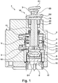
- FIG. 1 shows a sectional view of a cartridge 1 for adjusting a temperature and a flow rate of a mixed water.
- the cartridge 1 comprises a housing 2 which has a mixing chamber 3, a cold water inlet 4 leading into the mixing space 3 and a hot water inlet 5 leading into the mixing space 3.
- a first control element 8 which is axially movable along a movement axis 7, is arranged for setting a mixed water temperature.
- the first control element 8 can be moved in the axial direction Y in both directions. By shifting the first control element 8, a flow of a quantity of cold water through the cold water inlet 4 into the mixing space 3 can be controlled.
- the flow of a quantity of hot water through the hot water inlet 5 can be controlled.
- the first control element 8 of the cartridge 1 in the present embodiment for example, axially along the axis of movement 7 in the direction of the cold water inlet 4 are moved, so that the first control 8 the cold water inlet 4 at least partially shuts off. For example, if less cold water is fed into the mixing chamber 3, the temperature of the mixed water rises. Additionally or alternatively, more hot water can be passed into the mixing chamber 3 in order to increase the temperature of the mixed water.
- the first control 8 of the cartridge 1 in the present embodiment of FIG. 1 For example, be moved axially along the axis of movement 7 in the direction of the hot water inlet 5, so that the first control 8, the hot water supply 5 at least partially shuts off. For example, if less hot water is fed into the mixing chamber 3, the temperature of the mixed water drops. Additionally or alternatively, more cold water can be passed into the mixing chamber 3, so that the temperature of the mixed water decreases.
- this has a mixed water drain 6.
- the water thus has a flow direction through the cartridge 1, which leads from the cold water inlet 4 and the hot water inlet 5 through the mixing chamber 3 to the mixed water outlet 6.
- the cartridge 1 has a quantity control unit 9 downstream of the first control element 8 in the direction of flow.
- the quantity control unit 9 also comprises a second control element 10 which is rotatable about the movement axis 7.
- the second control element 10 is according to the exemplary embodiment of FIG FIG. 1 upstream of the mixed water outlet 6.
- the second control element 10 can at least partially block a mixed water flow from the mixing chamber 3 to the mixed water outlet 6, so that the flow rate of the mixed water can be adjusted.
- the second control element 10 can also shut off the mixed water flow, so that it succumbs.
- the cartridge 1 has an adjusting element 11.
- the adjusting element 11 can be moved axially along the movement axis 7.
- the adjusting element 11 may, as in FIG. 1 is shown to be formed as an adjusting shaft.
- a center line of the adjusting element 11 is thus equal to the movement axis 7.
- a movement axially along the movement axis 7 of the setting element 11 can be transmitted to the first control element 8. With the help of the adjusting element 11 thus the adjustment of the mixed water temperature can be made.
- the adjusting element 11 leads in the present embodiment in an outlet region 18 of the housing 2 of the cartridge 1.
- the adjusting member 11 further comprises an outside of the housing 2 arranged operating section 23.
- the adjusting element 11 may be coupled to the first control element 8 and the second control element 10 such that the first control element 8 can be axially displaced along the movement axis 7 and the second control element 10 can be rotated about the movement axis 7 by means of the adjusting element 11.
- the mixed water temperature and the flow rate of the mixed water through the cartridge 1 can be adjusted.
- a compact design of the sanitary fitting, in which the cartridge 1 is arranged, is possible.
- the adjustment member 11 coupled to the first control 8 axialkraftübertragend.
- the first control 8 blocks thereby at least partially the hot water inlet 5 and in the present embodiment, the cold water inlet 4 at least partially free, so that an inflow amount of hot water into the mixing chamber 3 at least reduced and an inflow amount of cold water is increased in the mixing chamber 3, so that the Mixed water temperature drops.
- a movement opposite to the movement just discussed causes the inflow amount of the cold water into the mixing chamber 3 at least reduced and the inflow of the hot water is at least increased in the mixing chamber 3, so that the mixed water temperature increases.
- the adjusting element 11 can also be mounted rotatably in the housing 2 about the movement axis 7.
- the adjusting element 11 can be rotated by an angle, for example, about a first rotation D1 in both directions of rotation.
- the adjusting element 11 can also be decoupled from the first axis of rotation 7 relative to the first rotation element D1.
- the first rotation D1 of the adjusting element 11 is not transmitted to the first control element 8.
- the adjusting element 11 and the first control element 8 need not necessarily be decoupled from each other with respect to the first rotation D1. Due to the rotational symmetry, the effect of the first control element 8 is also retained when it is rotated.
- the adjusting element 11 is connected to the second control element 10 to transmit torque.
- the first rotation D1 of the adjusting element 11 can thus be transmitted to the second control element 10.
- the first control element 8 can be decoupled from the first rotation D1 of the adjusting element 11.
- the second control element 10 is also fixed in the axial direction Y. Although the second control element 10 can rotate about the movement axis 7, the second control element 10 is fixed, so that a displacement axially along the movement axis 7 is not possible.
- the quantity control unit 9 can, for example, according to FIG. 1 one Paragraph 12, which engages in a recess 13 in the housing 2. Although the shoulder 12 can rotate in the recess 13, movement in the axial direction Y is prevented.
- a coupling connection 14 may be formed between the setting element 11 and the second control element 10.
- the coupling connection 14 may be designed as a positive connection which transmits a torque from the adjusting element 11 to the second control element 10, and / or permits a displacement in the axial direction Y of the adjusting element 11 relative to the second control element 10.
- the adjusting element 11 has a coupling end 15 facing the second control element 10.
- the second control element 10 also has a coupling recess 16 into which the coupling end 15 can engage. According to FIG. 1 engages the coupling end 15 in the circumferential direction positively and slidably in the axial direction Y in the coupling recess 16.
- the coupling end 15 is thereby fixed in the circumferential direction in the coupling recess 16, but is movable in the axial direction Y. Due to the positive connection, the first rotation D1 can be transmitted from the coupling end 15 via the coupling recess 16 to the second control element 10. Due to the axial displaceability of the coupling end 15 relative to the coupling recess 16, the adjusting element 11 is decoupled relative to the second control element 10 in the axial direction Y.
- the coupling end 15 may have an external toothing.
- the coupling recess 16 may have internal teeth.
- the cartridge 1 may have a valve element 17.
- the valve element 17 is advantageously fixedly connected to the housing 2.
- the valve element 17 is according to FIG. 1 downstream of the second control element 10.
- the valve element 17 and the second control element 10 may each have at least one passage opening, not shown here.
- the flow rate can be adjusted.
- the passage opening of the second control element 10 can preferably be aligned congruently with the passage opening of the valve element 17. A flow rate of the mixed water is thereby maximized.
- the cartridge 1 In order to move the adjusting element 11 axially along the movement axis 7, the cartridge 1 has an adjusting element 19 in the outlet region 18.
- the adjusting element 19 is screwed by means of a screw 20 in the housing 2.
- the adjustment also has two mutually axially spaced axial stops 21 and 22.
- the second axial stop 22 is only in the FIG. 2 to see.
- the adjusting element 19 is further fixed between the two axial stops 21, 22 on the adjusting element 11.
- the two axial stops 21, 22 may, for example, extend in the circumferential direction at least in sections around the adjusting element 11.
- a second rotation D2 of the adjusting element 19 can be converted into an axial displacement of the adjusting element 19 by means of the screw connection 20.
- the axial displacement of the adjusting element 19 can be transmitted to the adjusting element 11.
- the first control element 8 is moved in the mixing chamber 3. This in turn, as already described above, the mixed water temperature can be adjusted.
- the first control element 8, the second control element 10, the adjusting element 11 and the adjusting element 19 are preferably aligned coaxially with one another, as shown in the present exemplary embodiment.
- the two rotations D1 and D2 can be transmitted directly to the adjusting element 11 and the two control elements 8, 10. On deflection can be dispensed with.
- cartridge 1 can thus be adjusted by means of two rotations D1 and D2, the flow rate of the mixed water through the cartridge 1 and the mixed water temperature.
- the rotation D1 of the adjusting element 11 With the aid of the rotation D1 of the adjusting element 11, the flow rate of the mixed water through the cartridge 1 and with the aid of the rotation D2, the mixed water temperature can be adjusted.
- the two rotations D1 and D2 can be performed by means of an actuator, not shown here.
- the actuator may for example comprise an electric motor, which is preferably arranged coaxially to the adjusting element 11 and connected thereto.
- the two rotations D1 and D2 can advantageously be carried out with the aid of a single actuator.
- the two rotations D1 and D2 are advantageously aligned coaxially with each other, so that the two rotations D1 and D2 can be performed particularly easily by the actuator.
- the actuator can engage the adjusting element 11 and / or the operating section 23.
- the actuator can act on the adjusting element 19.
- FIG. 2 shows a perspective view of the cartridge 1 of FIG. 1
- the cold water inlet 4 and / or the hot water inlet 5 can according to the FIG. 2 extend circumferentially around the cartridge 1. Furthermore, the two inlets 4, 5 are spaced apart in the axial direction. You can see it in the FIG. 2
- the axial stops 21, 22 likewise extend around the circumferential direction of the adjusting element 11.
Landscapes
- Engineering & Computer Science (AREA)
- General Engineering & Computer Science (AREA)
- Mechanical Engineering (AREA)
- Multiple-Way Valves (AREA)
- Domestic Plumbing Installations (AREA)
Applications Claiming Priority (1)
| Application Number | Priority Date | Filing Date | Title |
|---|---|---|---|
| DE102017125865.5A DE102017125865A1 (de) | 2017-11-06 | 2017-11-06 | Kartusche für ein Sanitärelement sowie ein Sanitärelement |
Publications (1)
| Publication Number | Publication Date |
|---|---|
| EP3480498A1 true EP3480498A1 (fr) | 2019-05-08 |
Family
ID=64183828
Family Applications (1)
| Application Number | Title | Priority Date | Filing Date |
|---|---|---|---|
| EP18000869.0A Withdrawn EP3480498A1 (fr) | 2017-11-06 | 2018-11-06 | Cartouche pour un élément sanitaire ainsi qu'élément sanitaire |
Country Status (2)
| Country | Link |
|---|---|
| EP (1) | EP3480498A1 (fr) |
| DE (1) | DE102017125865A1 (fr) |
Citations (2)
| Publication number | Priority date | Publication date | Assignee | Title |
|---|---|---|---|---|
| DE69300578T2 (de) * | 1992-04-17 | 1996-03-21 | Vernet Sa | Verbesserungen von thermostatischen Kappen und Mischungsventilen mit solchen Kappen. |
| US20010007336A1 (en) * | 1999-12-03 | 2001-07-12 | Watts Eurotherm S.A. | Fluid flow control device housed in a thermostatic faucet |
-
2017
- 2017-11-06 DE DE102017125865.5A patent/DE102017125865A1/de active Pending
-
2018
- 2018-11-06 EP EP18000869.0A patent/EP3480498A1/fr not_active Withdrawn
Patent Citations (2)
| Publication number | Priority date | Publication date | Assignee | Title |
|---|---|---|---|---|
| DE69300578T2 (de) * | 1992-04-17 | 1996-03-21 | Vernet Sa | Verbesserungen von thermostatischen Kappen und Mischungsventilen mit solchen Kappen. |
| US20010007336A1 (en) * | 1999-12-03 | 2001-07-12 | Watts Eurotherm S.A. | Fluid flow control device housed in a thermostatic faucet |
Also Published As
| Publication number | Publication date |
|---|---|
| DE102017125865A1 (de) | 2019-05-09 |
Similar Documents
| Publication | Publication Date | Title |
|---|---|---|
| EP0162342B1 (fr) | Insert de contrôle pour mélangeur sanitaire | |
| DE3991109C2 (de) | Mischventil mit Druckausgleichsvorrichtung | |
| EP1895211B1 (fr) | Dispositif de ventilation pour une armature sanitaire et armature sanitaire | |
| DE2953331C1 (de) | Steuerungs- und Absperrventil fuer stroemende Medien | |
| EP0838625A2 (fr) | Dispositif de raccordement pour la connexion de deux éléments de tuyaux | |
| EP2171325B1 (fr) | Dispositif de réglage | |
| DE2364913A1 (de) | Anpassungsteil fuer installationsgegenstaende | |
| EP0197382A2 (fr) | Robinet mélangeur sans poignée | |
| EP3755927B1 (fr) | Soupape à disque en céramique | |
| DE10133041A1 (de) | Wasserarmatur | |
| EP0237473B1 (fr) | Dispositif de commande dans un robinet mélangeur à poignée unique | |
| EP0501953B1 (fr) | Melangeur sanitaire | |
| EP3480498A1 (fr) | Cartouche pour un élément sanitaire ainsi qu'élément sanitaire | |
| EP0653581A1 (fr) | Robinet mitigeur et d'arrêt | |
| DE3113653A1 (de) | Mischbatterie | |
| EP2406529A2 (fr) | Mélangeur à levier unique pour un robinet d'eau | |
| EP2206939B1 (fr) | Armature | |
| EP3859483B1 (fr) | Armature de mitigeur pourvu de soupape thermostatique compacte | |
| DE3911681A1 (de) | Mischhahn | |
| DE3043089A1 (de) | Mechanisch betaetigte brauchwassermischbatterie | |
| EP0246405B1 (fr) | Robinetterie sanitaire | |
| EP3832037B1 (fr) | Cartouche mélangeuse à un seul levier pour une robinetterie sanitaire | |
| DE102004022029B4 (de) | Ventil für sanitäre Anlagen | |
| DE102005001310A1 (de) | Sanitärarmatur | |
| DE2735354C3 (de) | Thermostatisch gesteuerte Mischarmatur, insbesondere für den Anschluß an Durchlauferhitzer |
Legal Events
| Date | Code | Title | Description |
|---|---|---|---|
| PUAI | Public reference made under article 153(3) epc to a published international application that has entered the european phase |
Free format text: ORIGINAL CODE: 0009012 |
|
| STAA | Information on the status of an ep patent application or granted ep patent |
Free format text: STATUS: THE APPLICATION HAS BEEN PUBLISHED |
|
| AK | Designated contracting states |
Kind code of ref document: A1 Designated state(s): AL AT BE BG CH CY CZ DE DK EE ES FI FR GB GR HR HU IE IS IT LI LT LU LV MC MK MT NL NO PL PT RO RS SE SI SK SM TR |
|
| AX | Request for extension of the european patent |
Extension state: BA ME |
|
| RAP3 | Party data changed (applicant data changed or rights of an application transferred) |
Owner name: GROHE AG |
|
| STAA | Information on the status of an ep patent application or granted ep patent |
Free format text: STATUS: THE APPLICATION IS DEEMED TO BE WITHDRAWN |
|
| 18D | Application deemed to be withdrawn |
Effective date: 20191109 |