EP3480656B1 - Anzeigesystem und -verfahren - Google Patents
Anzeigesystem und -verfahren Download PDFInfo
- Publication number
- EP3480656B1 EP3480656B1 EP17823450.6A EP17823450A EP3480656B1 EP 3480656 B1 EP3480656 B1 EP 3480656B1 EP 17823450 A EP17823450 A EP 17823450A EP 3480656 B1 EP3480656 B1 EP 3480656B1
- Authority
- EP
- European Patent Office
- Prior art keywords
- light
- solid
- light source
- display system
- state
- Prior art date
- Legal status (The legal status is an assumption and is not a legal conclusion. Google has not performed a legal analysis and makes no representation as to the accuracy of the status listed.)
- Active
Links
Images

Classifications
-
- G—PHYSICS
- G03—PHOTOGRAPHY; CINEMATOGRAPHY; ANALOGOUS TECHNIQUES USING WAVES OTHER THAN OPTICAL WAVES; ELECTROGRAPHY; HOLOGRAPHY
- G03B—APPARATUS OR ARRANGEMENTS FOR TAKING PHOTOGRAPHS OR FOR PROJECTING OR VIEWING THEM; APPARATUS OR ARRANGEMENTS EMPLOYING ANALOGOUS TECHNIQUES USING WAVES OTHER THAN OPTICAL WAVES; ACCESSORIES THEREFOR
- G03B21/00—Projectors or projection-type viewers; Accessories therefor
- G03B21/14—Details
- G03B21/20—Lamp housings
- G03B21/2006—Lamp housings characterised by the light source
- G03B21/2013—Plural light sources
-
- G—PHYSICS
- G03—PHOTOGRAPHY; CINEMATOGRAPHY; ANALOGOUS TECHNIQUES USING WAVES OTHER THAN OPTICAL WAVES; ELECTROGRAPHY; HOLOGRAPHY
- G03B—APPARATUS OR ARRANGEMENTS FOR TAKING PHOTOGRAPHS OR FOR PROJECTING OR VIEWING THEM; APPARATUS OR ARRANGEMENTS EMPLOYING ANALOGOUS TECHNIQUES USING WAVES OTHER THAN OPTICAL WAVES; ACCESSORIES THEREFOR
- G03B21/00—Projectors or projection-type viewers; Accessories therefor
- G03B21/005—Projectors using an electronic spatial light modulator but not peculiar thereto
-
- G—PHYSICS
- G03—PHOTOGRAPHY; CINEMATOGRAPHY; ANALOGOUS TECHNIQUES USING WAVES OTHER THAN OPTICAL WAVES; ELECTROGRAPHY; HOLOGRAPHY
- G03B—APPARATUS OR ARRANGEMENTS FOR TAKING PHOTOGRAPHS OR FOR PROJECTING OR VIEWING THEM; APPARATUS OR ARRANGEMENTS EMPLOYING ANALOGOUS TECHNIQUES USING WAVES OTHER THAN OPTICAL WAVES; ACCESSORIES THEREFOR
- G03B21/00—Projectors or projection-type viewers; Accessories therefor
- G03B21/14—Details
- G03B21/147—Optical correction of image distortions, e.g. keystone
-
- G—PHYSICS
- G03—PHOTOGRAPHY; CINEMATOGRAPHY; ANALOGOUS TECHNIQUES USING WAVES OTHER THAN OPTICAL WAVES; ELECTROGRAPHY; HOLOGRAPHY
- G03B—APPARATUS OR ARRANGEMENTS FOR TAKING PHOTOGRAPHS OR FOR PROJECTING OR VIEWING THEM; APPARATUS OR ARRANGEMENTS EMPLOYING ANALOGOUS TECHNIQUES USING WAVES OTHER THAN OPTICAL WAVES; ACCESSORIES THEREFOR
- G03B21/00—Projectors or projection-type viewers; Accessories therefor
- G03B21/14—Details
- G03B21/20—Lamp housings
-
- G—PHYSICS
- G03—PHOTOGRAPHY; CINEMATOGRAPHY; ANALOGOUS TECHNIQUES USING WAVES OTHER THAN OPTICAL WAVES; ELECTROGRAPHY; HOLOGRAPHY
- G03B—APPARATUS OR ARRANGEMENTS FOR TAKING PHOTOGRAPHS OR FOR PROJECTING OR VIEWING THEM; APPARATUS OR ARRANGEMENTS EMPLOYING ANALOGOUS TECHNIQUES USING WAVES OTHER THAN OPTICAL WAVES; ACCESSORIES THEREFOR
- G03B21/00—Projectors or projection-type viewers; Accessories therefor
- G03B21/14—Details
- G03B21/20—Lamp housings
- G03B21/2006—Lamp housings characterised by the light source
- G03B21/2033—LED or laser light sources
-
- G—PHYSICS
- G03—PHOTOGRAPHY; CINEMATOGRAPHY; ANALOGOUS TECHNIQUES USING WAVES OTHER THAN OPTICAL WAVES; ELECTROGRAPHY; HOLOGRAPHY
- G03B—APPARATUS OR ARRANGEMENTS FOR TAKING PHOTOGRAPHS OR FOR PROJECTING OR VIEWING THEM; APPARATUS OR ARRANGEMENTS EMPLOYING ANALOGOUS TECHNIQUES USING WAVES OTHER THAN OPTICAL WAVES; ACCESSORIES THEREFOR
- G03B21/00—Projectors or projection-type viewers; Accessories therefor
- G03B21/14—Details
- G03B21/20—Lamp housings
- G03B21/2053—Intensity control of illuminating light
-
- G—PHYSICS
- G03—PHOTOGRAPHY; CINEMATOGRAPHY; ANALOGOUS TECHNIQUES USING WAVES OTHER THAN OPTICAL WAVES; ELECTROGRAPHY; HOLOGRAPHY
- G03B—APPARATUS OR ARRANGEMENTS FOR TAKING PHOTOGRAPHS OR FOR PROJECTING OR VIEWING THEM; APPARATUS OR ARRANGEMENTS EMPLOYING ANALOGOUS TECHNIQUES USING WAVES OTHER THAN OPTICAL WAVES; ACCESSORIES THEREFOR
- G03B21/00—Projectors or projection-type viewers; Accessories therefor
- G03B21/14—Details
- G03B21/20—Lamp housings
- G03B21/2066—Reflectors in illumination beam
-
- G—PHYSICS
- G03—PHOTOGRAPHY; CINEMATOGRAPHY; ANALOGOUS TECHNIQUES USING WAVES OTHER THAN OPTICAL WAVES; ELECTROGRAPHY; HOLOGRAPHY
- G03B—APPARATUS OR ARRANGEMENTS FOR TAKING PHOTOGRAPHS OR FOR PROJECTING OR VIEWING THEM; APPARATUS OR ARRANGEMENTS EMPLOYING ANALOGOUS TECHNIQUES USING WAVES OTHER THAN OPTICAL WAVES; ACCESSORIES THEREFOR
- G03B21/00—Projectors or projection-type viewers; Accessories therefor
- G03B21/005—Projectors using an electronic spatial light modulator but not peculiar thereto
- G03B21/008—Projectors using an electronic spatial light modulator but not peculiar thereto using micromirror devices
-
- G—PHYSICS
- G03—PHOTOGRAPHY; CINEMATOGRAPHY; ANALOGOUS TECHNIQUES USING WAVES OTHER THAN OPTICAL WAVES; ELECTROGRAPHY; HOLOGRAPHY
- G03B—APPARATUS OR ARRANGEMENTS FOR TAKING PHOTOGRAPHS OR FOR PROJECTING OR VIEWING THEM; APPARATUS OR ARRANGEMENTS EMPLOYING ANALOGOUS TECHNIQUES USING WAVES OTHER THAN OPTICAL WAVES; ACCESSORIES THEREFOR
- G03B21/00—Projectors or projection-type viewers; Accessories therefor
- G03B21/14—Details
- G03B21/20—Lamp housings
- G03B21/208—Homogenising, shaping of the illumination light
Definitions
- the present disclosure relates to the field of projection and display, and in particular, to a display system and a method.
- An existing display mainly includes a light source, a first photoelectric modulator, an imaging system, a second photoelectric modulator, a projection screen, etc. Based on an image signal, two photoelectric modulators are required to control a light beam, resulting in a complex structure and error-prone situations.
- Another display system from the prior art US 2011/0222023 includes a light source configured to emit a plurality of light beams.
- the plurality of light beams enters a light-homogenized rod unit and is sent to a modulator via a set of relay lenses.
- an internal reflection prism is used to change a propagation direction of light. Since the internal reflection prism has a large light-cone angle when being spread, the resulting spherical aberration and the astigmatism will cause a large difference in dispersion degrees of light spots on the photoelectric modulator. This may result in distortion and color deviation, poor color uniformity and poor quality of image display during the system imaging.
- a display system in a first aspect of the present disclosure, includes: a light source device; an optical processing assembly; a reflection device; and a light modulator.
- the light source device is configured to emit a plurality of light beams.
- the optical processing assembly is configured to perform a light path adjustment on each light beam of the plurality of light beams from the light source device in such a manner that the light beam irradiates on the reflection device at a preset light-cone angle.
- the reflection device is configured to reflect the plurality of light beams from the optical processing assembly to the light modulator.
- the light modulator includes a plurality of sets of controllable units. The reflection device is adopted to make the light beam reflected by itself illuminates on a set of controllable units.
- the light modulator is configured to modulate the light beam by each controllable unit, so as to emit desired display light.
- the light source device is characterized in that a central axis direction between the light source device and the set of first relay lenses is a first direction, and a central axis direction between lenses of the set of second relay lenses is a second direction, and the first direction and the second direction are offset from each other by a preset angle of inclination.
- a display method includes:
- the laser beam emitted from the array of solid-state light sources is further modulated in the spatial light modulator, thereby emitting display light for generating a more approximate desired image.
- This can avoid errors that easily occur.
- the difference in dispersion degrees of the light spots on the spatial light modulator can be reduced, thereby reducing the distortion and color deviation in imaging of the display system, and thus improving the imaging quality and the display effect of the image.
- a display system includes a light source device 10, an optical processing assembly, a reflection device 30, a spatial light modulator 40, a controller, and a screen.
- the controller is respectively connected to the light source device 10 and the spatial light modulator 40.
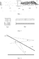
- the optical processing assembly includes a set of first relay lenses 201, a light-homogenized rod unit 202 and a set of second relay lenses 203.
- the light source device 10 is an array of solid-state light sources for emitting a plurality of light beams.
- the spatial light modulator 40 includes a plurality of controllable units, i.e., pixel units. Each solid-state light source of the light source device 10 emits a light beam corresponding to a set of pixel units of the spatial light modulator 40.
- the solid-state light source includes a laser device and a LED. Unless otherwise specified, the laser device and array of laser devices will be described by way of an example in the following.
- the controller first receives a control signal, which may be information on each pixel in one frame of image.
- the controller controls each laser device in the array of laser devices 10 to emit light in accordance with the control signal.
- the light emitted from each laser device has an independent state.
- each laser device can be controlled to turn on or turn off based on the control signal, or each laser device can emit laser beams having different light intensities or brightness based on the control signal.
- the light source device can also be designed as a single laser source with a light modulator. Each controllable unit of the light modulator separately modulates the laser that irradiates on it based on the control signal, until the laser emitted from the laser source is decomposed into light beams of different states.
- the array of laser devices 10 emits each laser beam to the set of first relay lenses 201.
- laser beams emitted from the array of laser devices 10 diverge to some extent and cannot be regarded as pure light.
- the laser beam emitting from the optical processing assembly is in a light-cone state with a light-cone angle.
- the set of first relay lenses 201 is used to converge the light beams to the light-homogenized rod unit 202.
- the light-homogenized rod unit 202 is in a form a rectangular array of light-homogenized rods as shown in FIG.
- FIG. 2(a) is a front view of rectangular light-homogenized rods
- FIG. 2(b) is a side view thereof.
- Each laser device in the array of laser devices 10 corresponds to a respective one light-homogenized rod of the array of light-homogenized rods 202, and the laser device and the light-homogenized rod correspond to a respective set of pixel units of the spatial light modulator 40.
- the set of second relay lenses 203 can adopt a classic TRP (tilt & roll pixel) illumination light path.
- the set of second relay lenses 203 can be formed by a combination of different lenses, and a purpose of its design is to adjust each light beam from the light-homogenized rod unit 202 in such a manner that each beam can irradiate on the reflection device 30 at a preset light-cone angle.
- the preset light-cone angle is 34° or smaller.
- the preset light-cone angle ranges from 16° to 34°.
- the light beam irradiates on the reflection device 30 at a preset light-cone angle of 34°.
- the angle of 34° is based on the principle of optical design, and is related to a flip angle of the controllable unit of the spatial light modulator 40 and can be adapted to optical elements based on actual needs.
- the spatial light modulator 40 preferably adopts a light-cone angle of 34°, and if it is larger than 34°, the optical efficiency and the imaging quality will be influenced.
- Those skilled in the art can design various optical processing assemblies in combination with conventional technical measures, without limitation to the structure in FIG. 1 , as long as the light-cone angle of the light emitted to the reflection device 30 is 34°.
- the reflection device 30 can adopt a total internal reflection mirror, which is configured in such a manner that an angle between a light-cone of a light beam from the optical processing assembly and a light-exiting surface of the total internal reflection mirror is in a range of 17°-51° (sharp angles).
- the angle between the light-cone of the light beam and the light-exiting surface of the total internal reflection mirror can be in another range, depending on a different light-cone angle of the light beam.
- the pixel unit of the spatial light modulator 40 can be achieved by a technique such as a transmittance-variable display device, a liquid crystal display device, or a digital mirror/micromirror device (DMD).
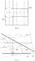
- FIG. 4 is a schematic plan view of a spatial light modulator 40.
- the spatial light modulator 40 includes a plurality of independently addressable pixel units 401 (or DMD lenses).
- An irradiation area 001' of each light-cone reflected by the reflection device 30 corresponds to one set of pixel units.
- a set of pixel units includes one or more pixel units.
- the array of laser devices 10 is in a one-to-one mapping relationship with a working surface of the DMD that is equally divided into hundreds of parts.
- the control signal is also used to control nine pixel units 401 corresponding to an irradiation area 003'.
- the nine pixel units 401 respectively correspond to individual signal values.
- the nine pixel units 401 are controlled to have individual deflection angles or individual durations, so that light passing through each pixel unit 401 has a different brightness, light amount, or a transmittance, etc.
- the irradiation area 003' is formed by the laser 003 passing through the reflection device 30.
- One pixel unit 401 may further include independently addressable sub-pixel units 4011, which may be associated with, for example, a particular color such as red, green, and blue.
- Those skilled in the art can also use other conventional technical measures to simultaneously control at the array of laser devices 10 end and at the spatial light modulator 40 end, so that the laser beam emitted from the array of laser devices 10 can be further modulated in the spatial light modulator 40.
- An original image can be obtained by only the array of laser devices 10, and display light that is more approximate to the desired image can be obtained through further modulation by the spatial light modulator 40. This can ensure a sufficient dark image occurring in a dark area outside the area with the maximum brightness in the image, so that the dark image has a more delicate and rich image level, and thus the viewer can have a better visual experience when the display light is projected onto the screen and imaged.
- the optical path control principle of this embodiment will be briefly summarized as follows.
- the array of laser devices 10 emits light beams, and each laser device corresponds to one light-homogenized rod in the array of light-homogenized rods 202 and corresponds to a set of DMD lenses.
- the intensity of the light beam emitted from each laser device can be modulated by controlling the laser device, and the intensity of the light beam incident on the set of DMD lenses corresponding to the laser device is controlled by controlling the flip angle/duration of some or all of the DMD lenses of the set of DMD lenses, so that the light beam is reflected to the lens. That is, the laser device and the set of DMD lenses are controlled in series, and the light beam is controlled both at the laser device end and at the DMD lens end.
- a direction of a central axis between the light source device 10 and the set of first relay lenses 201 is a first direction
- a direction of a central axis between the lenses in the set of second relay lenses 203 is a second direction.
- both the first direction and the second direction each are generally designed as a horizontal direction.
- a surface of the spatial light modulator 40 for receiving the light is also in the horizontal direction.
- two light beams i.e., a first light-cone 001 and a second light-cone 002
- a light axis direction of the first light-cone 001 and a light axis direction of the second light-cone 002 are also the horizontal direction.
- an apexes of the light-cones (which can be considered to have a diameter d') are not all exactly in the horizontal line. As shown in FIG.
- an irradiation area 002' on the spatial light modulator 40 formed by the second light-cone 002 overlaps exactly with a set of pixel units, and its diameter is d'.
- An irradiation area 001' on the spatial light modulator 40 formed by the first light-cone 001 is larger, and its diameter d1 is beyond the area of a set of pixel units. Therefore, this phenomenon of the display system in the related art causes a large difference in dispersion degrees of many light spots (i.e., the irradiation areas), which affects controlling the light by the spatial light modulator 40, and reduces the imaging quality.
- the array of laser devices 10 is tilted upward by a preset angle of inclination relative to the horizontal direction, for example, the array of laser devices 10 is tilted upward by 2°-3°. That is, the first direction is a direction tilted upward by 2°-3° relative to the horizontal direction, and the second direction is the horizontal direction. Then, the first light-cone 001 and the second light-cone 002 irradiate on the reflection device 30, the direction of the light axis of the first light-cone 001 and the direction of the light axis of the second light-cone 002 are also tilted upward by 2°-3° relative to the horizontal direction.
- an irradiation area on the spatial light modulator 40 formed by the second light-cone 002 overlaps exactly with a set of pixels.
- a diameter of an irradiation area on the spatial light modulator 40 formed by the first light-cone 001 is d2. It can be clearly seen that d2 is smaller than d1. In other words, compared with the related art, the display system in this embodiment has a smaller or negligible difference in dispersion degrees of the light spots on the photoelectric modulator 40, and the imaging quality is improved.
- the direction of the central axis between the lenses in the set of second relay lenses 203 may be tilted upward by a preset angle with respect to the horizontal direction, and the first direction is the horizontal direction; or the direction of the central axis between the lenses in the optical processing assembly may be tilted upward by a preset angle with respect to the horizontal direction, and the first direction is the horizontal direction; or both the first direction and the second direction are tilted upward by a preset angle, so that the direction of the light axis of the first light-cone 001 and the direction of the light axis of the second light-cone 002 are tilted upward by a preset angle relative to the horizontal direction.
- the preset angle may be tilted upward relative to the horizontal direction or may be tilted downward relative to the horizontal direction, depending on the actual configuration of the display system.
- the first direction or the second direction can be offset from the vertical direction by a preset angle, so that the direction of the light axis of the first light-cone 001 and the direction of the light axis of the second light-cone 002 are offset from the vertical direction by a preset angle.
- the display system in this embodiment can have a smaller difference in dispersion degrees of the light spots on the photoelectric modulator 40, and the imaging quality and the display effect of the image can be improved.
- the display system and the display method of the present disclosure can be used in the field of High-Dynamic Range (HDR) digital imaging and projection display technologies, for example, in a Digital Light Procession (DLP) projector using TRP illumination.
- HDR High-Dynamic Range
- DLP Digital Light Procession
- the laser source can be switched and modulated at a high speed so that each laser source can achieve a function of the first photoelectric modulator, and the laser beam emitted from the array of laser devices 10 can be further modulated at the spatial light modulator 40. That is, the HDR function can be achieved by separately controlling each laser device and the DMD local area mapped thereto, thereby emitting display light for generating a more approximate desired image.
- the present disclosure uses only one spatial light modulator, which not only simplifies the light path structure, but also avoids errors that are easily caused by controlling two spatial light modulators. In this way, it is more in line with the interests of the users, and it can ensure a sufficient dark image occurring in a dark area outside the area with the maximum brightness in the image, so that the dark image has a more delicate and rich image level, and thus the viewer can have a better visual experience.
- the problem of a large difference in dispersion degrees of the light spots on the spatial light modulator in the conventional display system is solved, thereby reducing the distortion and color deviation in the imaging of the display system.
- the brightness and the color are more uniform, and the image is more similar to the object, thereby improving the imaging quality and the display effect of the image.
- the solution of these problems can allow the technician to design a more detailed mapping relationship in the DMD working surface, and provide a better hardware support for achieving the HDR function.
- the present disclosure does not require any addition optical element or light modulator while achieving significant improvements by using the cost and condition in the related art, so the present disclosure is of great significance to the developers, manufacturers and users of display systems.
Landscapes
- Physics & Mathematics (AREA)
- General Physics & Mathematics (AREA)
- Optics & Photonics (AREA)
- Engineering & Computer Science (AREA)
- Multimedia (AREA)
- Signal Processing (AREA)
- Mechanical Light Control Or Optical Switches (AREA)
- Projection Apparatus (AREA)
- Optical Modulation, Optical Deflection, Nonlinear Optics, Optical Demodulation, Optical Logic Elements (AREA)
Claims (10)
- Anzeigesystem, umfassend:eine Lichtquellenvorrichtung (10);eine optische Verarbeitungsanordnung;eine Reflexionsvorrichtung (30); undeinen Lichtmodulator (40);wobei die Lichtquellenvorrichtung konfiguriert ist, um eine Vielzahl von Lichtstrahlen zu emittieren, wobei die optische Verarbeitungsanordnung einen Satz von ersten Relaislinsen (201);eine lichthomogenisierte Stabeinheit (202) und einen Satz zweiter Relaislinsen (203) umfasst; wobei der Satz von ersten Relaislinsen konfiguriert ist, um die Vielzahl von Lichtstrahlen von derLichtquellenvorrichtung zu der lichthomogenisierten Stabeinheit zu konvergieren, wobei die lichthomogenisierte Stabeinheit konfiguriert ist, um eine Homogenisierung auf jedem Lichtstrahl aus dem Satz von ersten Relaislinsen durchzuführen und den Lichtstrahl an den Satz von zweiten Relaislinsen zu übertragen, und der Satz von zweiten Relaislinsen konfiguriert ist, um jeden Lichtstrahl von der lichthomogenisierten Stabeinheit derart anzupassen, dass jeder Lichtstrahl in einem voreingestellten Lichtkegelwinkel auf die Reflexionvorrichtung ausgestrahlt wird,wobei die Reflexionsvorrichtung konfiguriert ist, um die Vielzahl von Lichtstrahlen von der optischen Verarbeitungsanordnung zu dem Lichtmodulator zu reflektieren, undder Lichtmodulator eine Vielzahl von Sätzen von steuerbaren Einheiten umfasst, wobei jeder durch die Reflexionsvorrichtung reflektierte Lichtstrahl einem jeweiligen Satz der Vielzahl von Sätzen von steuerbaren Einheiten entspricht, und der Lichtmodulator konfiguriert ist, um eine oder mehrere steuerbare Einheiten in dem jeweiligen Satz von steuerbaren Einheiten zu steuern, um den Lichtstrahl, der dem Satz von steuerbaren Einheiten entspricht, zu modulieren, um gewünschtes Anzeigelicht zu emittieren,dadurch gekennzeichnet, dass eine Mittelachsenrichtung zwischen der Lichtquellenvorrichtung und dem Satz von ersten Relaislinsen eine erste Richtung ist und eine Mittelachsenrichtung zwischen Linsen des Satzes von zweiten Relaislinsen eine zweite Richtung ist und die erste Richtung und die zweite Richtung um einen voreingestellten Neigungswinkel voneinander versetzt sind.
- Anzeigesystem nach Anspruch 1, dadurch gekennzeichnet, dass die Lichtquellenvorrichtung einen Array von Festkörperlichtquellen (10) umfasst, die konfiguriert sind, um eine Vielzahl von Laserstrahlen (003) zu emittieren, und ein Laserstrahl, der von jeder Festkörperlichtquelle in dem Array von Festkörperlichtquellen emittiert wird, einem Satz der Vielzahl von Sätzen von steuerbaren Einheiten des Lichtmodulators entspricht.
- Anzeigesystem nach Anspruch 2, dadurch gekennzeichnet, dass es ferner umfasst:eine Steuerung, die mit der Lichtquellenvorrichtung und dem Lichtmodulator verbunden ist,wobei die Steuerung konfiguriert ist, um ein Steuersignal zu empfangen, einen Lichtemissionszustand einer Festkörperlichtquelle in dem Array von Festkörperlichtquellen gemäß dem Steuersignal zu steuern und einen Modulationszustand von einer oder mehrerer steuerbaren Einheiten des Satzes von steuerbaren Einheiten, die der Festkörperlichtquelle entsprechen, derart zu steuern, dass der Lichtmodulator den von der Festkörperlichtquelle emittierten Lichtstrahl moduliert und gewünschtes Anzeigelicht gemäß dem Steuersignal emittiert.
- Anzeigesystem nach Anspruch 1, dadurch gekennzeichnet, dass die lichthomogenisierte Stabeinheit (202) ein rechteckiger Array von lichthomogenisierten Stäben ist, und jede Lichtquelle in dem Array von Festkörperlichtquellen in einer Eins-zu-Eins-Entsprechung zu einem jeweiligen lichthomogenisierten Stab des Arrays von lichthomogenisierten Stäben ist, und die Festkörperlichtquelle und der lichthomogenisierte Stab einem jeweiligen Satz von steuerbaren Einheiten (401) des Lichtmodulators entsprechen.
- Anzeigesystem nach Anspruch 1, dadurch gekennzeichnet, dass der voreingestellte Lichtkegelwinkel in einem Bereich von 16°-34° liegt.
- System nach einem der Ansprüche 1 bis 3, dadurch gekennzeichnet, dass die Reflexionsvorrichtung (30) in einer Weise derart eingerichtet ist, dass ein Winkel zwischen einem Lichtstrahl in einer Form eines Lichtkegels von der optischen Verarbeitungsanordnung und einer Lichtaustrittsoberfläche der Reflexionsvorrichtung in einem Bereich von 17°-51° liegt.
- Anzeigesystem nach einem der Ansprüche 1 bis 3, gekennzeichnet durch ein weiteres Umfassen eines Projektionsschirms, der konfiguriert ist, um Anzeigelicht von dem Lichtmodulator zu empfangen, um ein Bild anzuzeigen.
- Anzeigesystem nach Anspruch 1, dadurch gekennzeichnet, dass die erste Richtung und die zweite Richtung um 2°-3° voneinander versetzt sind.
- Anzeigesystem nach Anspruch 1, dadurch gekennzeichnet, dass die erste Richtung eine horizontale/vertikale Richtung ist und die zweite Richtung von der horizontalen/vertikalen Richtung um den voreingestellten Neigungswinkel versetzt ist; oder die zweite Richtung eine horizontale/vertikale Richtung ist und die erste Richtung von der horizontalen/vertikalen Richtung um den voreingestellten Neigungswinkel versetzt ist.
- Anzeigeverfahren, gekennzeichnet durch Verwenden des Anzeigesystems nach einem der Ansprüche 1 bis 9, wobei das Anzeigeverfahren umfasst:Steuern des Arrays von Festkörperlichtquellen (10), um Licht zu emittieren und zum Steuern jeder Festkörperlichtquelle in dem Array von Festkörperlichtquellen, um eine Intensität eines Lichtstrahls zu modulieren, der von der Festkörperlichtquelle emittiert wird; undSteuern eines Flipwinkels/einer Dauer einer oder mehrerer steuerbare Einheiten (401) des Satzes von steuerbaren Einheiten, die der Festkörperlichtquelle entsprechen, wodurch die Intensität des Lichtstrahls, der aus dem Satz von steuerbaren Einheiten emittiert wird, gesteuert wird.
Applications Claiming Priority (2)
| Application Number | Priority Date | Filing Date | Title |
|---|---|---|---|
| CN201610519561.1A CN107577108B (zh) | 2016-07-04 | 2016-07-04 | 一种显示系统及方法 |
| PCT/CN2017/082409 WO2018006638A1 (zh) | 2016-07-04 | 2017-04-28 | 一种显示系统及方法 |
Publications (3)
| Publication Number | Publication Date |
|---|---|
| EP3480656A1 EP3480656A1 (de) | 2019-05-08 |
| EP3480656A4 EP3480656A4 (de) | 2020-03-11 |
| EP3480656B1 true EP3480656B1 (de) | 2022-10-12 |
Family
ID=60901701
Family Applications (1)
| Application Number | Title | Priority Date | Filing Date |
|---|---|---|---|
| EP17823450.6A Active EP3480656B1 (de) | 2016-07-04 | 2017-04-28 | Anzeigesystem und -verfahren |
Country Status (4)
| Country | Link |
|---|---|
| US (1) | US11003064B2 (de) |
| EP (1) | EP3480656B1 (de) |
| CN (1) | CN107577108B (de) |
| WO (1) | WO2018006638A1 (de) |
Families Citing this family (2)
| Publication number | Priority date | Publication date | Assignee | Title |
|---|---|---|---|---|
| CN113495405A (zh) * | 2020-03-19 | 2021-10-12 | 深圳光峰科技股份有限公司 | 投影系统 |
| CN113038103A (zh) * | 2021-03-22 | 2021-06-25 | 青岛海信激光显示股份有限公司 | 应用于激光显示设备的激光投影主机和激光显示设备 |
Family Cites Families (29)
| Publication number | Priority date | Publication date | Assignee | Title |
|---|---|---|---|---|
| JPH10254370A (ja) * | 1997-03-10 | 1998-09-25 | Canon Inc | 表示パネル及びそれを用いた投射型表示装置 |
| WO2001069584A1 (en) * | 2000-03-14 | 2001-09-20 | Mitsubishi Denki Kabushiki Kaisha | Image display and image displaying method |
| JP2002350775A (ja) * | 2001-05-30 | 2002-12-04 | Fuji Photo Optical Co Ltd | プロジェクタ装置 |
| EP1485904B1 (de) * | 2002-03-13 | 2012-08-29 | Dolby Laboratories Licensing Corporation | Anzeige-vorrichtung mit grosser dynamik |
| US6724546B2 (en) * | 2002-04-25 | 2004-04-20 | Mitsubishi Denki Kabushiki Kaisha | Light converging optical system for converging light onto a reflecting optical-spatial modulator element and image displaying apparatus for displaying an image formed by light reflected by the reflecting optical-spatial modulator element |
| CN1383034A (zh) * | 2002-05-24 | 2002-12-04 | 杭州浙大科特光电科技有限公司 | 液晶背投影电视光学引擎 |
| JP4082332B2 (ja) * | 2003-04-11 | 2008-04-30 | セイコーエプソン株式会社 | 表示装置およびプロジェクタ |
| CN100378496C (zh) * | 2003-06-02 | 2008-04-02 | 明锐有限公司 | 具有隐藏铰链的高填充率反射式空间光调制器 |
| KR100677551B1 (ko) | 2005-01-05 | 2007-02-02 | 삼성전자주식회사 | Led 패키지, 조명계 및 이를 채용한 프로젝션 시스템 |
| CN1847975A (zh) * | 2005-04-05 | 2006-10-18 | 中强光电股份有限公司 | 投影机的光源装置 |
| CN101109488A (zh) * | 2007-08-23 | 2008-01-23 | 福州高意光学有限公司 | 多基色led的发光结构及其在投影机和照明系统中的应用 |
| CN101387815B (zh) * | 2007-09-12 | 2010-09-29 | 鸿富锦精密工业(深圳)有限公司 | 投影机 |
| US8451427B2 (en) * | 2007-09-14 | 2013-05-28 | Nikon Corporation | Illumination optical system, exposure apparatus, optical element and manufacturing method thereof, and device manufacturing method |
| CN101424768A (zh) * | 2007-11-02 | 2009-05-06 | 北京京东方光电科技有限公司 | 导光板、背光源及液晶显示器 |
| US7551341B1 (en) | 2008-01-28 | 2009-06-23 | Dolby Laboratories Licensing Corporation | Serial modulation display having binary light modulation stage |
| CN102239445A (zh) * | 2008-12-05 | 2011-11-09 | 三洋电机株式会社 | 照明装置及投射型影像显示装置 |
| CN103597400B (zh) * | 2011-04-12 | 2017-05-03 | 巴库股份有限公司 | 散斑减少的激光投影仪 |
| CN102269920B (zh) * | 2011-07-21 | 2013-01-23 | 凝辉(天津)科技有限责任公司 | 一种分离式微型激光投影装置 |
| EP2776888A4 (de) * | 2011-11-08 | 2015-06-10 | Reald Inc | Fleckenminderung bei bildgebungspfaden |
| US8860640B2 (en) | 2012-05-30 | 2014-10-14 | Christie Digital Systems Usa, Inc. | Zonal illumination for high dynamic range projection |
| JP5910324B2 (ja) * | 2012-06-04 | 2016-04-27 | ソニー株式会社 | 照明装置、投影型表示装置および直視型表示装置 |
| CN103913937B (zh) * | 2013-01-01 | 2016-04-20 | 深圳市光峰光电技术有限公司 | 发光装置及其相关投影系统 |
| CN104049445B (zh) * | 2013-03-11 | 2016-12-28 | 深圳市绎立锐光科技开发有限公司 | 发光装置及投影系统 |
| KR20150114763A (ko) * | 2014-04-02 | 2015-10-13 | 삼성전자주식회사 | 프로젝터 |
| CN104062838A (zh) * | 2014-07-08 | 2014-09-24 | 深圳市安华光电技术有限公司 | 一种互动投影光学系统及其工作方法 |
| CN105334687B (zh) * | 2014-08-01 | 2019-04-12 | 欧司朗股份有限公司 | 投影系统 |
| CN204178113U (zh) * | 2014-10-31 | 2015-02-25 | 深圳市绎立锐光科技开发有限公司 | 发光装置及具有其的投影仪 |
| US10281805B2 (en) * | 2015-07-17 | 2019-05-07 | Nec Display Solutions, Ltd. | Image display device and image display method |
| CN205984148U (zh) * | 2016-07-04 | 2017-02-22 | 深圳市光峰光电技术有限公司 | 一种显示系统 |
-
2016
- 2016-07-04 CN CN201610519561.1A patent/CN107577108B/zh active Active
-
2017
- 2017-04-28 US US16/314,899 patent/US11003064B2/en active Active
- 2017-04-28 EP EP17823450.6A patent/EP3480656B1/de active Active
- 2017-04-28 WO PCT/CN2017/082409 patent/WO2018006638A1/zh not_active Ceased
Also Published As
| Publication number | Publication date |
|---|---|
| CN107577108A (zh) | 2018-01-12 |
| EP3480656A4 (de) | 2020-03-11 |
| US20190155137A1 (en) | 2019-05-23 |
| CN107577108B (zh) | 2019-09-20 |
| EP3480656A1 (de) | 2019-05-08 |
| US11003064B2 (en) | 2021-05-11 |
| WO2018006638A1 (zh) | 2018-01-11 |
Similar Documents
| Publication | Publication Date | Title |
|---|---|---|
| JP7108770B2 (ja) | 高ダイナミックレンジ画像プロジェクタのための方法およびシステム | |
| EP2670144B1 (de) | Zonenbeleuchtung mit hoher dynamischer Bereichsprojektion | |
| EP2869570B1 (de) | Zweistufige Lichtmodulation mit weitem Dynamikbereich | |
| US12407797B2 (en) | Laser projection device and projection display method thereof | |
| JP2004523001A5 (de) | ||
| TW201602556A (zh) | 具有投影光源的攝像方法及其攝像裝置 | |
| CN105988266A (zh) | 投影设备、投影控制系统及投影控制方法 | |
| CN207164451U (zh) | 投影系统 | |
| US20160327783A1 (en) | Projection display system and method | |
| CN107797368B (zh) | 双空间光调制系统及使用该系统进行光调节的方法 | |
| CN107888891A (zh) | 图像投影显示方法和光学引擎 | |
| EP3848753B1 (de) | Lichtquellensystem und steuerverfahren dafür, anzeigevorrichtung und steuerverfahren dafür | |
| JP2014178686A5 (de) | ||
| CN205984148U (zh) | 一种显示系统 | |
| CN112637576B (zh) | 投影设备以及投影控制方法 | |
| EP3931607A1 (de) | Verfahren und system zur räumlichen und winkligen vereinheitlichung von lichtstrahlen | |
| EP3480656B1 (de) | Anzeigesystem und -verfahren | |
| KR101419966B1 (ko) | 하나의 개구 변조 단계를 포함하여, 2개의 변조 단계를 갖는 투사 영상 디스플레이 장치 | |
| CN210431678U (zh) | 采用自发光像素阵列器件的投影显示装置 | |
| CN113031257A (zh) | 一种显示系统 | |
| KR19980040064A (ko) | 광학적 투사 시스템 및 이를 이용한 광 투사 방법 | |
| JP2023529104A (ja) | 回転可能なアナモルフィックレンズを有する投影システム | |
| HK1209939B (en) | Two-stage light modulation for high dynamic range | |
| TW201546563A (zh) | 可調整曝光強度的曝光系統 |
Legal Events
| Date | Code | Title | Description |
|---|---|---|---|
| STAA | Information on the status of an ep patent application or granted ep patent |
Free format text: STATUS: THE INTERNATIONAL PUBLICATION HAS BEEN MADE |
|
| PUAI | Public reference made under article 153(3) epc to a published international application that has entered the european phase |
Free format text: ORIGINAL CODE: 0009012 |
|
| STAA | Information on the status of an ep patent application or granted ep patent |
Free format text: STATUS: REQUEST FOR EXAMINATION WAS MADE |
|
| 17P | Request for examination filed |
Effective date: 20190115 |
|
| AK | Designated contracting states |
Kind code of ref document: A1 Designated state(s): AL AT BE BG CH CY CZ DE DK EE ES FI FR GB GR HR HU IE IS IT LI LT LU LV MC MK MT NL NO PL PT RO RS SE SI SK SM TR |
|
| AX | Request for extension of the european patent |
Extension state: BA ME |
|
| DAV | Request for validation of the european patent (deleted) | ||
| DAX | Request for extension of the european patent (deleted) | ||
| A4 | Supplementary search report drawn up and despatched |
Effective date: 20200212 |
|
| RIC1 | Information provided on ipc code assigned before grant |
Ipc: G03B 21/20 20060101AFI20200206BHEP |
|
| GRAP | Despatch of communication of intention to grant a patent |
Free format text: ORIGINAL CODE: EPIDOSNIGR1 |
|
| STAA | Information on the status of an ep patent application or granted ep patent |
Free format text: STATUS: GRANT OF PATENT IS INTENDED |
|
| INTG | Intention to grant announced |
Effective date: 20220512 |
|
| GRAS | Grant fee paid |
Free format text: ORIGINAL CODE: EPIDOSNIGR3 |
|
| GRAA | (expected) grant |
Free format text: ORIGINAL CODE: 0009210 |
|
| STAA | Information on the status of an ep patent application or granted ep patent |
Free format text: STATUS: THE PATENT HAS BEEN GRANTED |
|
| AK | Designated contracting states |
Kind code of ref document: B1 Designated state(s): AL AT BE BG CH CY CZ DE DK EE ES FI FR GB GR HR HU IE IS IT LI LT LU LV MC MK MT NL NO PL PT RO RS SE SI SK SM TR |
|
| REG | Reference to a national code |
Ref country code: GB Ref legal event code: FG4D |
|
| REG | Reference to a national code |
Ref country code: CH Ref legal event code: EP |
|
| REG | Reference to a national code |
Ref country code: DE Ref legal event code: R096 Ref document number: 602017062632 Country of ref document: DE |
|
| REG | Reference to a national code |
Ref country code: IE Ref legal event code: FG4D |
|
| REG | Reference to a national code |
Ref country code: AT Ref legal event code: REF Ref document number: 1524523 Country of ref document: AT Kind code of ref document: T Effective date: 20221115 |
|
| REG | Reference to a national code |
Ref country code: LT Ref legal event code: MG9D |
|
| REG | Reference to a national code |
Ref country code: NL Ref legal event code: MP Effective date: 20221012 |
|
| REG | Reference to a national code |
Ref country code: AT Ref legal event code: MK05 Ref document number: 1524523 Country of ref document: AT Kind code of ref document: T Effective date: 20221012 |
|
| PG25 | Lapsed in a contracting state [announced via postgrant information from national office to epo] |
Ref country code: NL Free format text: LAPSE BECAUSE OF FAILURE TO SUBMIT A TRANSLATION OF THE DESCRIPTION OR TO PAY THE FEE WITHIN THE PRESCRIBED TIME-LIMIT Effective date: 20221012 |
|
| PG25 | Lapsed in a contracting state [announced via postgrant information from national office to epo] |
Ref country code: SE Free format text: LAPSE BECAUSE OF FAILURE TO SUBMIT A TRANSLATION OF THE DESCRIPTION OR TO PAY THE FEE WITHIN THE PRESCRIBED TIME-LIMIT Effective date: 20221012 Ref country code: PT Free format text: LAPSE BECAUSE OF FAILURE TO SUBMIT A TRANSLATION OF THE DESCRIPTION OR TO PAY THE FEE WITHIN THE PRESCRIBED TIME-LIMIT Effective date: 20230213 Ref country code: NO Free format text: LAPSE BECAUSE OF FAILURE TO SUBMIT A TRANSLATION OF THE DESCRIPTION OR TO PAY THE FEE WITHIN THE PRESCRIBED TIME-LIMIT Effective date: 20230112 Ref country code: LT Free format text: LAPSE BECAUSE OF FAILURE TO SUBMIT A TRANSLATION OF THE DESCRIPTION OR TO PAY THE FEE WITHIN THE PRESCRIBED TIME-LIMIT Effective date: 20221012 Ref country code: FI Free format text: LAPSE BECAUSE OF FAILURE TO SUBMIT A TRANSLATION OF THE DESCRIPTION OR TO PAY THE FEE WITHIN THE PRESCRIBED TIME-LIMIT Effective date: 20221012 Ref country code: ES Free format text: LAPSE BECAUSE OF FAILURE TO SUBMIT A TRANSLATION OF THE DESCRIPTION OR TO PAY THE FEE WITHIN THE PRESCRIBED TIME-LIMIT Effective date: 20221012 Ref country code: AT Free format text: LAPSE BECAUSE OF FAILURE TO SUBMIT A TRANSLATION OF THE DESCRIPTION OR TO PAY THE FEE WITHIN THE PRESCRIBED TIME-LIMIT Effective date: 20221012 |
|
| PG25 | Lapsed in a contracting state [announced via postgrant information from national office to epo] |
Ref country code: RS Free format text: LAPSE BECAUSE OF FAILURE TO SUBMIT A TRANSLATION OF THE DESCRIPTION OR TO PAY THE FEE WITHIN THE PRESCRIBED TIME-LIMIT Effective date: 20221012 Ref country code: PL Free format text: LAPSE BECAUSE OF FAILURE TO SUBMIT A TRANSLATION OF THE DESCRIPTION OR TO PAY THE FEE WITHIN THE PRESCRIBED TIME-LIMIT Effective date: 20221012 Ref country code: LV Free format text: LAPSE BECAUSE OF FAILURE TO SUBMIT A TRANSLATION OF THE DESCRIPTION OR TO PAY THE FEE WITHIN THE PRESCRIBED TIME-LIMIT Effective date: 20221012 Ref country code: IS Free format text: LAPSE BECAUSE OF FAILURE TO SUBMIT A TRANSLATION OF THE DESCRIPTION OR TO PAY THE FEE WITHIN THE PRESCRIBED TIME-LIMIT Effective date: 20230212 Ref country code: HR Free format text: LAPSE BECAUSE OF FAILURE TO SUBMIT A TRANSLATION OF THE DESCRIPTION OR TO PAY THE FEE WITHIN THE PRESCRIBED TIME-LIMIT Effective date: 20221012 Ref country code: GR Free format text: LAPSE BECAUSE OF FAILURE TO SUBMIT A TRANSLATION OF THE DESCRIPTION OR TO PAY THE FEE WITHIN THE PRESCRIBED TIME-LIMIT Effective date: 20230113 |
|
| REG | Reference to a national code |
Ref country code: DE Ref legal event code: R097 Ref document number: 602017062632 Country of ref document: DE |
|
| PG25 | Lapsed in a contracting state [announced via postgrant information from national office to epo] |
Ref country code: SM Free format text: LAPSE BECAUSE OF FAILURE TO SUBMIT A TRANSLATION OF THE DESCRIPTION OR TO PAY THE FEE WITHIN THE PRESCRIBED TIME-LIMIT Effective date: 20221012 Ref country code: RO Free format text: LAPSE BECAUSE OF FAILURE TO SUBMIT A TRANSLATION OF THE DESCRIPTION OR TO PAY THE FEE WITHIN THE PRESCRIBED TIME-LIMIT Effective date: 20221012 Ref country code: EE Free format text: LAPSE BECAUSE OF FAILURE TO SUBMIT A TRANSLATION OF THE DESCRIPTION OR TO PAY THE FEE WITHIN THE PRESCRIBED TIME-LIMIT Effective date: 20221012 Ref country code: DK Free format text: LAPSE BECAUSE OF FAILURE TO SUBMIT A TRANSLATION OF THE DESCRIPTION OR TO PAY THE FEE WITHIN THE PRESCRIBED TIME-LIMIT Effective date: 20221012 Ref country code: CZ Free format text: LAPSE BECAUSE OF FAILURE TO SUBMIT A TRANSLATION OF THE DESCRIPTION OR TO PAY THE FEE WITHIN THE PRESCRIBED TIME-LIMIT Effective date: 20221012 |
|
| PLBE | No opposition filed within time limit |
Free format text: ORIGINAL CODE: 0009261 |
|
| STAA | Information on the status of an ep patent application or granted ep patent |
Free format text: STATUS: NO OPPOSITION FILED WITHIN TIME LIMIT |
|
| PG25 | Lapsed in a contracting state [announced via postgrant information from national office to epo] |
Ref country code: SK Free format text: LAPSE BECAUSE OF FAILURE TO SUBMIT A TRANSLATION OF THE DESCRIPTION OR TO PAY THE FEE WITHIN THE PRESCRIBED TIME-LIMIT Effective date: 20221012 Ref country code: AL Free format text: LAPSE BECAUSE OF FAILURE TO SUBMIT A TRANSLATION OF THE DESCRIPTION OR TO PAY THE FEE WITHIN THE PRESCRIBED TIME-LIMIT Effective date: 20221012 |
|
| 26N | No opposition filed |
Effective date: 20230713 |
|
| PG25 | Lapsed in a contracting state [announced via postgrant information from national office to epo] |
Ref country code: SI Free format text: LAPSE BECAUSE OF FAILURE TO SUBMIT A TRANSLATION OF THE DESCRIPTION OR TO PAY THE FEE WITHIN THE PRESCRIBED TIME-LIMIT Effective date: 20221012 |
|
| REG | Reference to a national code |
Ref country code: CH Ref legal event code: PL |
|
| PG25 | Lapsed in a contracting state [announced via postgrant information from national office to epo] |
Ref country code: LU Free format text: LAPSE BECAUSE OF NON-PAYMENT OF DUE FEES Effective date: 20230428 |
|
| REG | Reference to a national code |
Ref country code: BE Ref legal event code: MM Effective date: 20230430 |
|
| PG25 | Lapsed in a contracting state [announced via postgrant information from national office to epo] |
Ref country code: MC Free format text: LAPSE BECAUSE OF FAILURE TO SUBMIT A TRANSLATION OF THE DESCRIPTION OR TO PAY THE FEE WITHIN THE PRESCRIBED TIME-LIMIT Effective date: 20221012 |
|
| PG25 | Lapsed in a contracting state [announced via postgrant information from national office to epo] |
Ref country code: MC Free format text: LAPSE BECAUSE OF FAILURE TO SUBMIT A TRANSLATION OF THE DESCRIPTION OR TO PAY THE FEE WITHIN THE PRESCRIBED TIME-LIMIT Effective date: 20221012 Ref country code: LI Free format text: LAPSE BECAUSE OF NON-PAYMENT OF DUE FEES Effective date: 20230430 Ref country code: CH Free format text: LAPSE BECAUSE OF NON-PAYMENT OF DUE FEES Effective date: 20230430 |
|
| REG | Reference to a national code |
Ref country code: IE Ref legal event code: MM4A |
|
| PG25 | Lapsed in a contracting state [announced via postgrant information from national office to epo] |
Ref country code: BE Free format text: LAPSE BECAUSE OF NON-PAYMENT OF DUE FEES Effective date: 20230430 |
|
| PG25 | Lapsed in a contracting state [announced via postgrant information from national office to epo] |
Ref country code: IE Free format text: LAPSE BECAUSE OF NON-PAYMENT OF DUE FEES Effective date: 20230428 |
|
| PG25 | Lapsed in a contracting state [announced via postgrant information from national office to epo] |
Ref country code: IE Free format text: LAPSE BECAUSE OF NON-PAYMENT OF DUE FEES Effective date: 20230428 |
|
| PG25 | Lapsed in a contracting state [announced via postgrant information from national office to epo] |
Ref country code: IT Free format text: LAPSE BECAUSE OF FAILURE TO SUBMIT A TRANSLATION OF THE DESCRIPTION OR TO PAY THE FEE WITHIN THE PRESCRIBED TIME-LIMIT Effective date: 20221012 |
|
| PG25 | Lapsed in a contracting state [announced via postgrant information from national office to epo] |
Ref country code: BG Free format text: LAPSE BECAUSE OF FAILURE TO SUBMIT A TRANSLATION OF THE DESCRIPTION OR TO PAY THE FEE WITHIN THE PRESCRIBED TIME-LIMIT Effective date: 20221012 |
|
| PG25 | Lapsed in a contracting state [announced via postgrant information from national office to epo] |
Ref country code: BG Free format text: LAPSE BECAUSE OF FAILURE TO SUBMIT A TRANSLATION OF THE DESCRIPTION OR TO PAY THE FEE WITHIN THE PRESCRIBED TIME-LIMIT Effective date: 20221012 |
|
| PGFP | Annual fee paid to national office [announced via postgrant information from national office to epo] |
Ref country code: DE Payment date: 20250411 Year of fee payment: 9 |
|
| PGFP | Annual fee paid to national office [announced via postgrant information from national office to epo] |
Ref country code: GB Payment date: 20250417 Year of fee payment: 9 |
|
| PGFP | Annual fee paid to national office [announced via postgrant information from national office to epo] |
Ref country code: FR Payment date: 20250429 Year of fee payment: 9 |
|
| PG25 | Lapsed in a contracting state [announced via postgrant information from national office to epo] |
Ref country code: CY Free format text: LAPSE BECAUSE OF FAILURE TO SUBMIT A TRANSLATION OF THE DESCRIPTION OR TO PAY THE FEE WITHIN THE PRESCRIBED TIME-LIMIT; INVALID AB INITIO Effective date: 20170428 |
|
| PG25 | Lapsed in a contracting state [announced via postgrant information from national office to epo] |
Ref country code: HU Free format text: LAPSE BECAUSE OF FAILURE TO SUBMIT A TRANSLATION OF THE DESCRIPTION OR TO PAY THE FEE WITHIN THE PRESCRIBED TIME-LIMIT; INVALID AB INITIO Effective date: 20170428 |
|
| PG25 | Lapsed in a contracting state [announced via postgrant information from national office to epo] |
Ref country code: TR Free format text: LAPSE BECAUSE OF FAILURE TO SUBMIT A TRANSLATION OF THE DESCRIPTION OR TO PAY THE FEE WITHIN THE PRESCRIBED TIME-LIMIT Effective date: 20221012 |