EP3480906A1 - Modulares belüftungssystem - Google Patents
Modulares belüftungssystem Download PDFInfo
- Publication number
- EP3480906A1 EP3480906A1 EP18164911.2A EP18164911A EP3480906A1 EP 3480906 A1 EP3480906 A1 EP 3480906A1 EP 18164911 A EP18164911 A EP 18164911A EP 3480906 A1 EP3480906 A1 EP 3480906A1
- Authority
- EP
- European Patent Office
- Prior art keywords
- ventilation system
- ventilation
- temperature
- unit
- housing assembly
- Prior art date
- Legal status (The legal status is an assumption and is not a legal conclusion. Google has not performed a legal analysis and makes no representation as to the accuracy of the status listed.)
- Pending
Links
Images


Classifications
-
- H—ELECTRICITY
- H02—GENERATION; CONVERSION OR DISTRIBUTION OF ELECTRIC POWER
- H02B—BOARDS, SUBSTATIONS OR SWITCHING ARRANGEMENTS FOR THE SUPPLY OR DISTRIBUTION OF ELECTRIC POWER
- H02B1/00—Frameworks, boards, panels, desks, casings; Details of substations or switching arrangements
- H02B1/56—Cooling; Ventilation
- H02B1/565—Cooling; Ventilation for cabinets
-
- H—ELECTRICITY
- H05—ELECTRIC TECHNIQUES NOT OTHERWISE PROVIDED FOR
- H05K—PRINTED CIRCUITS; CASINGS OR CONSTRUCTIONAL DETAILS OF ELECTRIC APPARATUS; MANUFACTURE OF ASSEMBLAGES OF ELECTRICAL COMPONENTS
- H05K7/00—Constructional details common to different types of electric apparatus
- H05K7/20—Modifications to facilitate cooling, ventilating, or heating
Definitions
- the invention generally relates to a ventilation system. More particularly, the present invention relates to a ventilation system for air circulation. Furthermore particularly, the present invention relates to the ventilation system for an enclosure of electrical components.
- Switchgear enclosures are commonly employed in electrical power distribution systems for enclosing circuit breakers and other switching equipment associated with the distribution system.
- switchgear enclosures are comprised of a number of individual stacked or adjacent compartments, and receive electrical power from a power source and distribute is the electrical power through one or more feeder circuits to one or more loads.
- Switchgear enclosures typically include circuit protection device for interrupting electric power in a particular feeder circuit in response to hazardous current overloads in the circuit.
- a circuit protection device in electrical equipment can be a circuit breaker, fuse and switch combination, contactor and fuse combination or any other device intended to break or protect the load or secondary side of a circuit.
- Switchgear is a general term covering switching and interrupting devices and their combination with associated control, instruments, metering, protective and regulating devices, and assemblies of these devices with associated interconnections, accessories, and supporting structures used primarily in connection with the generation, transmission, distribution, and conversion of electric power.
- the rated continuous current of metal-enclosed (ME) switchgear is the maximum current that can be carried continuously by the primary circuit components, including buses and connections, without producing a temperature in excess of specified limits for any primary or secondary circuit component, any insulating medium, or any structural or enclosing member.
- PSC power gear and control gear assemblies
- One object of the present invention is to provide an improved and a cost effective ventilation system.
- Another object of the present invention is to provide a digital based ventilation system.
- Yet another object of the invention is to provide an automated ventilation system to improve the effective ventilation in the electrical enclosure and providing a system with less maintenance cost.
- Yet another object of the present invention is to provide a system for controlling the temperature inside the electrical enclosure.
- Yet another object of the present invention is to provide a protection to the electrical components from failure due to heat.
- Yet another object of the present invention is to provide a heat dissipation system in each of the phase housings in the electrical enclosure.
- Yet another object of the present invention is to provide an automated fan based ventilation system.
- Yet another object of the present invention is to provide a sensor based automated ventilation system for the enclosure having electrical components.
- Yet another object of the invention is to detect a fault in the enclosure having electrical components.
- Yet another object of the invention is to provide a system with higher electrical rating for the same configuration.
- Yet another object of the invention is to detect a rise in temperature at a hottest point in the switchboard or the enclosure having electrical components, and trigger the system for heat dissipation through the ventilation system.
- Yet another object of the invention is to provide a breakdown prevention system to raise an alarm based on heat detection in the ventilation system.
- Yet another object of the invention to reduce the scalability overheads by increasing the heat dissipation capacity from the enclosure having electrical components.
- Yet another object of the invention is to permit the pressure and hot gases to be released without the risk of injury to personnel who might be working near the switchgear.
- a ventilation system for an enclosure of electrical components comprising a plurality of housing assemblies. Further, each of a housing assembly from the plurality of housing assemblies is a phase housing assembly. The system further comprising a terminal located at a first position in the phase housing assembly. Further, the terminal is a low resistant terminal. The system further comprising a temperature controlling device for each of the terminal located at a second position. The second position is beneath the first position in the ventilation system for ventilation.
- any terms used herein such as but not limited to “includes,” “comprises,” “has,” “consists,” and grammatical variants thereof do NOT specify an exact limitation or restriction and certainly do NOT exclude the possible addition of one or more features or elements, unless otherwise stated, and furthermore must NOT be taken to exclude the possible removal of one or more of the listed features and elements, unless otherwise stated with the limiting language “MUST comprise” or “NEEDS TO include.”
- a machine-readable medium includes any mechanism for storing or transmitting information in a form readable by a machine (e.g., a computer).
- a machine-readable medium includes read only memory ("ROM”); random access memory (“RAM”); magnetic disk storage media; optical storage media; flash memory devices; and electrical, optical, acoustical or other form of propagated signals (e.g., carrier waves, infrared signals, digital signals, etc.), just to mention a few examples.
- An “enclosure for electrical components” corresponds to an enclosure having plurality of electrical components in the switchgear panel for the electrical power distribution. Further, the enclosure may constitute many other protection circuits. In an embodiment of the present invention, the enclosure for electrical components may comprise plurality of devices, such as but not limited to sensors, ventilation fan, wires, connectors, various other electrical circuits.
- a “ventilation system” refers to an electronic device integrated with other sensors, fan unit, and electronic control unit.
- a ventilation system is an automated ventilation system. In an embodiment, when the temperature rises beyond a certain pre-defined temperature range, then the system automatically triggers the fan.
- a "housing assembly” corresponds to a house for plurality of phase housing assemblies in the enclosure.
- each of the phase housing assembly has a low resistant terminal.
- plurality of phase housing assemblies is connected to each other.
- a "low resistant terminal” corresponds to a point in a phase housing assembly where the temperature or the heat may be maximum.
- the low resistant terminal is also a connection point of a bus bar and an air circuit breaker where the maximum heat may be generated.
- a fan is located below the low resistant terminal.
- a "first position" corresponds to a position of terminal in the phase housing assembly.
- the terminal is a low resistant terminal in the phase housing assembly.
- a "second position" corresponds to a position below the first position in the phase housing assembly.
- a temperature controlling device is located at the second position.
- a "temperature controlling device” corresponds to a fan unit.
- the fan unit gets triggered when the temperature at the low resistant terminal is above a pre-defined temperature range.
- the temperature controlling device is protected by a breakdown protection unit which raises an alarm upon prediction of temperature rise in the system.
- each of the temperature controlling devices may be operable individually.
- One or more sensors refers to integrated sensors in the system configured to sense at least an absolute temperature value and a heat value.
- various other sensors such as smoke, fire, alarms may also be incorporated in the system for protection.
- FIG. 1 illustrates a block diagram of ventilation system 100, in accordance with the embodiment of the present invention
- a block diagram of ventilation system 100 is shown.
- the ventilation system 100 comprises of a breaker terminal unit 102, an electronic control unit 104, a relay unit 106, a memory unit 108, a display unit 110, a current transformer 112, a fan unit 114, a signal lamp 116, and one or more sensors 118.
- the breaker terminal unit 102 includes suitable logic, circuitry, and/or interfaces that are configured to break the circuit in case of detection of rise in temperature or failure of the fan unit 114.
- the breaker terminal unit 102 may be communicatively connected with the electronic control unit 104, the relay unit 106, the memory unit 108, the display unit 110, the current transformer 112, the fan unit 114, the signal lamp 116, and the one or more sensors 118.
- the electronic control unit 104 includes suitable logic, circuitry, and/or interfaces that are configured to control the entire ventilation system. A plurality of microcontrollers may be integrated in the electronic control unit 104. Furthermore, the electronic control unit 104 may be communicatively coupled with the breaker terminal unit 102, the relay unit 106, the memory unit 108, the display unit 110, the current transformer 112, the fan unit 114, the signal lamp 116, and the one or more sensors 118.
- the electronic control unit 104 may regulate the entire ventilation system and may further regulate the fan unit based on the temperature in the system.
- the controller may correspond to a microprocessor that is coupled to the plurality of ventilation modules through communication network.
- the controller includes suitable logic, circuitry, and/or interfaces that are operable to execute one or more instructions stored in the memory unit 210 to perform operations.
- the controller may be implemented using one or more processor technologies known in the art. Examples of the controller include, but are not limited to, an x86 microprocessor, a RISC microprocessor, an ASIC microprocessor, a CISC microprocessor, or any other microprocessor.
- the controller may be communicatively coupled with the breaker terminal unit 102, electronic control unit 104, the relay unit 106, the memory unit 108, the display unit 110, the current transformer 112, the fan unit 114, the signal lamp 116, and the one or more sensors 118.
- the controller may be integral part of the electronic control unit 104.
- the controller may be capable of performing more than one operation in parallel.
- the controller may be a multi-threaded processor, which may execute more than one process concurrently. Each such process may be executed to perform an operation, for e.g. controlling of the fan unit 114 by comparing the temperature generated due to heat and the temperature range stored in the micro controller by the user.
- the relay unit 106 includes suitable circuitry that is configured to connect or disconnect the fan unit from the entire system. In an embodiment of the present invention. Furthermore, the relay unit 106 may be communicatively coupled with the breaker terminal unit 102, electronic control unit 104, the memory unit 108, the display unit 110, the current transformer 112, the fan unit 114, the signal lamp 116, and the one or more sensors 118.
- the memory unit 108 includes suitable logic, circuitry, and/or interfaces that are operable to store the various readings.
- the memory unit 210 may be operable to store the one or more instructions.
- the memory unit 108 may store the time interval defined by the user to continuously monitor the temperature or heat value in the system to detect the fault.
- the various readings may correspond to the information, which may be utilized to protect the entire system.
- the memory may correspond to a RAM type or a ROM type. Further, the memory unit may be communicatively attached to the rest of the electrical distribution system and collects the data from all sensors and other integrated devices in each of the fan units.
- the memory unit 108 may transmit the information to remote servers at a pre-defined time interval, using communication medium, such as wireless communication medium. Further the memory unit 108 may also store data about the faults and the time stamp of the faults, number of times the fault has occurred and the alike.
- the display unit 110 may comprise suitable logic, circuitry, interfaces, and/or code that may be operable to render a display.
- the display device may be located at each of the fan units to display various readings and statics, such as current value, the leakage current value, fan speed, and various alarms etc.
- the display unit may have illumination for an easy display of plurality of readings.
- the display unit 110 may be further integrated with the communication network to communicate the data to the remotely located servers. Furthermore, the display unit 110 may be communicatively coupled with the breaker terminal unit 102, electronic control unit 104, relay unit 106, the memory unit 108, the current transformer 112, the fan unit 114, the signal lamp 116, and the one or more sensors 118. In an embodiment, the display unit 110 may be a touch panel which may enable the user to configure the range of temperature for each of the fan units 114 in the enclosure.
- the current transformer 112 may be configured to measure value of a current flowing in the enclosure. Furthermore, the current transformer 112 may be a current sensing unit of the power system. Current transformers are used at generating stations, electrical substations, and in industrial and commercial electric power distribution.
- the current transformer 112 may include a primary winding, a core, and a secondary winding (not shown).
- the fan unit 114 may be configured to exhaust the heat generated in the system.
- the fan unit 114 may be an automated digital operable fan unit 114.
- a plurality of fan units, each located at the hot spot below ACB terminal, may be configured to run at different speeds.
- the fan unit 114 may be controlled by the controller.
- the controller may be connected with the ON/OFF mechanism of the fan unit 114.
- the relay unit 106 along with the one or more sensors 118 may control the regulation of the fan unit 114.
- all the fan units in the enclosure may run simultaneously based on the detection of rise in temperature by the one or more sensors.
- the fan units may be functional based on the demand of the user or one or more user defined parameters, such as but not limited to a user defined time interval for each of the fan unit in the enclosure or a fixed time stamp to ON each of the fan unit in the enclosure.
- the signal lamp 116 may be configured to blown up in case of any system failure. In an embodiment, when the heat or temperature goes beyond specified limit in the enclosure, then the signal lamp may lighten up and reflects the error to the user. Furthermore, in an alternate embodiment, the signal lamp 116 may get lighten up when the system may be in proper working mode and no error may be detected.
- the one or more sensors 118 may comprise suitable logic, circuitry, interfaces, and/or code that may be operable to sense at least the temperature at the hot spot.
- a thermal sensor may be mounted on the hot spot of the switchgear and the bus bar. The sensor may be configured to measure an absolute temperature of the hot spot, and further to send the signal to the micro controller.
- the communication network may include connections such as wire, wireless communication links, or fiber optic cables.
- the communication network (not shown) may also be implemented using WLAN, Bluetooth or any other communication technology.
- the communication network may employ any network topology, transmission medium, or network protocol.
- the user may control (trigger function) the fan units 114 from a remote location through a wireless communication channel.
- the speed of the fan unit 114 may be dynamically regulated by the user based on the requirement of the heat generation in the system.
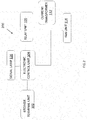
- FIG. 2 illustrates a system for breakdown prevention unit in the ventilation system, in accordance with the embodiment of the present invention.
- the output of thermal sensor may be connected to the input of microprocessor based controller (integrated in the electronic control unit 104) which in turn takes the decision to switch ON or OFF the fans by use of relay unit 106.
- the micro controller may be configured with an allowable maximum temperature at given point of temperature measurement.
- the output of micro controller may be connected to each fan unit 302a, 302b, and 302c (as shown in figure 3 ) for its ON-OFF control.
- each of the ON-OFF control of the fan units may be configured to operate at different temperatures.
- sensors may be connected to ACB terminals of R, Y and B phase (not shown) and further connected to the micro controller.
- Each output of controller is configured to operate at different temperature.
- O/P-1 at 80°C
- O/P-2 at 85°C
- O/P-3 at 90°C.
- O/P-1 relay may get activate and switch ON Fan-A.
- O/P-2 relay may get activated and switch ON fan-B.
- O/P-3 will switch ON Fan-C.
- O/P-4 may actuate alarm/ mounted on the panel in the enclosure.
- the micro controller in each of the ventilation module may be configured based on a location, such that a cut off temperature of fan in the ventilation module A may be different from the cut off temperature of fan in the ventilation module B or C having fan units 302a, 302b, and 302c.
- the number of ventilation modules o the fan units may be based on plurality of factors such as but not limited to the capacity of the entire system.
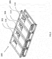
- FIG. 3 illustrates a set of housing assemblies in the electrical enclosure, in accordance with the embodiment of the present invention.
- FIG 300 a set of housing assemblies in the electrical enclosure are shown.
- each of the phase housing assembly includes ventilation module for ventilation, which includes at least a fan unit 114, microprocessor based controller (not shown) and mounting arrangement. Further, the mounting arrangement is placed below the R Terminal of Circuit breaker. The Module is placed in such a way that the fan unit 114 is below the hottest point, and the module may be inserted from front and then screwed to the casing which holds the module in its place.
- each of the phase housing assembly includes ventilation module for ventilation, which includes at least a fan unit 114, microprocessor based controller and mounting arrangement. Further, the mounting arrangement is placed below the Y Terminal of Circuit breaker. The Module is placed in such a way that the fan unit 114 is below the hottest point, and the module may be inserted from front and then screwed to the casing which holds the module in its place.
- each of the phase housing assembly includes ventilation module for ventilation, which includes at least a fan unit 114, microprocessor based controller and mounting arrangement. Further, the mounting arrangement is placed below the B Terminal of Circuit breaker. The Module is placed in such a way that the fan unit 114 is below the hottest point, and the module may be inserted from front and then screwed to the casing which holds the module in its place.
- the above mentioned housing assemblies (302, 304, and 306) may be interconnected with each other for current flow in the system.
- the connection in case of failure of one housing assembly, the connection may be altered in such a manner that the system may bypass the current from the failed housing assembly and rest of the system may remain in operational condition.
- the fan units 114 may direct cool air sucked through louvers provided on surface of the enclosure to the ACB terminal (hot spot), and the hot air coming from the hot spot may be released to the external environment through ventilation roof and louvers provided on the top of the enclosure.
- the temperature controlling device 114 is operable based on a user defined trigger function.
- the trigger function may correspond to a defined temperature range by the user to operate the fan unit 114.
- each of the fan unit 114 may have different operable temperature range.
- the user may define the second position based on the heat generation in the system. The second position may correspond to the position of the fan units 114.
- Figure 4 illustrates a hot spot in the housing assembly in the electrical enclosure, in accordance with the embodiment of the present invention.
- the hot spot 402 may correspond to a point of intersection of terminal of air circuit breaker and the bus bars.
- the current is passed in the air circuit breaker at the point of intersection.
- the space at the point of intersection is very low, therefore maximum heat may be generated at this point.
- the fan unit 114 as discussed in figure 3 may be placed below these hot spots 402.
- one or more sensors 118 may be mounted on identified hot spot 402 of the switchgear and busbar. These one or more sensors 118 may be configured to measure the absolute temperature of the hot spot and send signal to micro controller. These one or more sensors 118 may be suitable operate efficiently up to 150°C. Further, in an embodiment, a thermal monitoring device is attached to the terminals of circuit breaker and connected to a plug 404 mounted on the ventilation module. In an embodiment, when the module is moved inside then the plug 404 makes the connection.
- a power distribution enclosure may constitute three fan units that are configured to regulate the heat inside the enclosure.
- the user may define the range of temperature for each of the fan unit in the micro controller associated with each of the fan unit.
- Further temperature sensors may be mounted on a hot spot which is an intersection point of switch gear and bus bars in the enclosure. These temperature sensors may be configured to measure an absolute temperature of the hot spot in the enclosure and thereafter sends the signals to the micro controller.
- the micro controller determines the action to ON/OFF the fan unit based on the user defined temperature range. When the micro controller determines that the temperature of any fan unit goes beyond the defined temperature range, then it actuates the fan in ON mode and continuously monitors the change in the temperature.
- the micro controller In case, the temperature still rises beyond the specified limits of the other fan units, then it actuates other fan units as well. Lastly, in case of further rise in temperature, the micro controller actuates the alarms, and closes the entire system. This enables the user to protect the fan units from failure and thereafter, the micro controller sends the failure signal to the display device associated with the system.
Landscapes
- Engineering & Computer Science (AREA)
- Power Engineering (AREA)
- Physics & Mathematics (AREA)
- Thermal Sciences (AREA)
- Microelectronics & Electronic Packaging (AREA)
- Cooling Or The Like Of Electrical Apparatus (AREA)
Applications Claiming Priority (1)
| Application Number | Priority Date | Filing Date | Title |
|---|---|---|---|
| IN201741038827 | 2017-11-01 |
Publications (1)
| Publication Number | Publication Date |
|---|---|
| EP3480906A1 true EP3480906A1 (de) | 2019-05-08 |
Family
ID=61837665
Family Applications (1)
| Application Number | Title | Priority Date | Filing Date |
|---|---|---|---|
| EP18164911.2A Pending EP3480906A1 (de) | 2017-11-01 | 2018-03-29 | Modulares belüftungssystem |
Country Status (3)
| Country | Link |
|---|---|
| EP (1) | EP3480906A1 (de) |
| CN (1) | CN109757074B (de) |
| RU (1) | RU2689876C1 (de) |
Cited By (2)
| Publication number | Priority date | Publication date | Assignee | Title |
|---|---|---|---|---|
| CN119787111A (zh) * | 2024-12-20 | 2025-04-08 | 苏州开关二厂有限公司 | 一种一体化静态无功补偿装置 |
| CN120016314A (zh) * | 2025-04-17 | 2025-05-16 | 安徽明坤电器设备有限公司 | 一种配电柜的远程检测智能控制方法及装置 |
Citations (6)
| Publication number | Priority date | Publication date | Assignee | Title |
|---|---|---|---|---|
| DE29601769U1 (de) * | 1996-02-02 | 1997-06-12 | Aeg Sachsenwerk Gmbh, 93055 Regensburg | Schaltgerät mit wärmeabgebenden Bauteilen |
| DE19847454A1 (de) * | 1998-10-15 | 2000-05-04 | Alstom Sachsenwerk Gmbh | Belüftungsvorrichtung zum zwangsweise Belüften von Schaltgeräten und Schaltfeldanordnung zum Einsatz in einer luftisolierten Schaltanlage |
| US20060012954A1 (en) * | 2004-07-19 | 2006-01-19 | Jur Arthur J | Network protector added load ability through forced convection |
| US20070115630A1 (en) * | 2005-11-21 | 2007-05-24 | Midgley Stephen G | Electrical distribution apparatus with controlled cooling |
| EP2256884A1 (de) * | 2009-05-28 | 2010-12-01 | ABB S.p.A. | kühlung von Anschlusskontakten eines Einschubgeräts |
| US9007746B2 (en) * | 2012-12-12 | 2015-04-14 | Siemens Industry, Inc. | Modular draw out fan module with chimney design for cooling components in low voltage switchgear |
Family Cites Families (11)
| Publication number | Priority date | Publication date | Assignee | Title |
|---|---|---|---|---|
| US4772999A (en) * | 1986-12-16 | 1988-09-20 | Merlin Gerin | Static converter, especially for an uninterruptible electrical power supply system |
| US20080112135A1 (en) * | 2006-11-10 | 2008-05-15 | Toshiba International Corporation | Outdoor Medium Voltage Drive |
| JP5344182B2 (ja) * | 2010-02-02 | 2013-11-20 | 株式会社安川電機 | 電力変換装置 |
| RU97884U1 (ru) * | 2010-05-31 | 2010-09-20 | Александр Александрович Иванов | Станция управления насосной установкой |
| CN102458084B (zh) * | 2010-10-29 | 2016-05-11 | 鸿富锦精密工业(深圳)有限公司 | 数据中心及其散热系统 |
| RU106438U1 (ru) * | 2011-03-29 | 2011-07-10 | Общество с ограниченной ответственностью "МЕТОД" | Комплектный трехфазный сглаживающий фильтр для частотного преобразователя |
| US20150382496A1 (en) * | 2013-04-19 | 2015-12-31 | Richard Burant, Jr. | Electronic device and battery enclosure |
| JP5497234B1 (ja) * | 2013-08-20 | 2014-05-21 | 株式会社辰巳菱機 | 負荷試験装置 |
| FI126380B (en) * | 2014-10-27 | 2016-11-15 | Kone Corp | The drive unit |
| DE202016102587U1 (de) * | 2016-05-13 | 2016-06-10 | Schaffner Emv Ag | Filter |
| CN206283124U (zh) * | 2016-12-27 | 2017-06-27 | 天津市创辉津控科技发展有限公司 | 一种智能配电柜 |
-
2018
- 2018-03-28 CN CN201810263633.XA patent/CN109757074B/zh active Active
- 2018-03-29 EP EP18164911.2A patent/EP3480906A1/de active Pending
- 2018-03-29 RU RU2018111254A patent/RU2689876C1/ru active
Patent Citations (6)
| Publication number | Priority date | Publication date | Assignee | Title |
|---|---|---|---|---|
| DE29601769U1 (de) * | 1996-02-02 | 1997-06-12 | Aeg Sachsenwerk Gmbh, 93055 Regensburg | Schaltgerät mit wärmeabgebenden Bauteilen |
| DE19847454A1 (de) * | 1998-10-15 | 2000-05-04 | Alstom Sachsenwerk Gmbh | Belüftungsvorrichtung zum zwangsweise Belüften von Schaltgeräten und Schaltfeldanordnung zum Einsatz in einer luftisolierten Schaltanlage |
| US20060012954A1 (en) * | 2004-07-19 | 2006-01-19 | Jur Arthur J | Network protector added load ability through forced convection |
| US20070115630A1 (en) * | 2005-11-21 | 2007-05-24 | Midgley Stephen G | Electrical distribution apparatus with controlled cooling |
| EP2256884A1 (de) * | 2009-05-28 | 2010-12-01 | ABB S.p.A. | kühlung von Anschlusskontakten eines Einschubgeräts |
| US9007746B2 (en) * | 2012-12-12 | 2015-04-14 | Siemens Industry, Inc. | Modular draw out fan module with chimney design for cooling components in low voltage switchgear |
Cited By (2)
| Publication number | Priority date | Publication date | Assignee | Title |
|---|---|---|---|---|
| CN119787111A (zh) * | 2024-12-20 | 2025-04-08 | 苏州开关二厂有限公司 | 一种一体化静态无功补偿装置 |
| CN120016314A (zh) * | 2025-04-17 | 2025-05-16 | 安徽明坤电器设备有限公司 | 一种配电柜的远程检测智能控制方法及装置 |
Also Published As
| Publication number | Publication date |
|---|---|
| CN109757074B (zh) | 2022-12-13 |
| CN109757074A (zh) | 2019-05-14 |
| RU2689876C1 (ru) | 2019-05-29 |
Similar Documents
| Publication | Publication Date | Title |
|---|---|---|
| US11552458B2 (en) | Distribution panel for intelligently controlled solid-state circuit breakers | |
| US7495876B2 (en) | Circuit breaker integral temperature monitoring for advance detection of defective power conductor connections | |
| KR101194021B1 (ko) | 다면적 온도감지를 이용한 배전반 | |
| US9478950B2 (en) | Integrated safety disconnects for power systems | |
| US9831664B1 (en) | Integrated circuit breaker panels | |
| US20100142108A1 (en) | Network unit including network transformer and network protector | |
| KR102476147B1 (ko) | 부스바 온도 및 내부 복합 화재 검출이 가능한 센서 모듈을 구비한 수배전반, 분전반, 모터 제어반의 진단 시스템 | |
| KR101208579B1 (ko) | 배전반 감시 및 알림 시스템과 이를 이용한 감시 및 알림 방법 | |
| KR101723217B1 (ko) | 수배전반 내에서 스스로 정확한 동작 여부를 진단하고 및 동작이 부정확하면 경보를 울리는 자가진단모듈, 및 이를 포함하는 수배전반 | |
| US10594246B2 (en) | Board-level motor control system with integrated protection and control components | |
| CN113785375A (zh) | 电能传输装置的监视方法 | |
| KR20180003978A (ko) | 수배전반 내에서 스스로 정확한 동작 여부를 진단하고 및 동작이 부정확하면 경보를 울리는 자가진단모듈, 및 이를 포함하는 수배전반 | |
| EP3480906A1 (de) | Modulares belüftungssystem | |
| KR102185020B1 (ko) | 전력선 통신을 이용한 배전반 내 차단기의 계통 분석 시스템 | |
| EP3467865B1 (de) | Kabelkanal, sicherungssockel und überwachungssystem | |
| KR100300138B1 (ko) | 수변전 장치 | |
| KR101595079B1 (ko) | 중앙제어감시가 가능한 수배전반 자가진단 시스템 | |
| EP2760041B1 (de) | Vorrichtung zur Relaisnachrüstung in einer elektrischen Unterstation | |
| CN111564833A (zh) | 危险环境电反馈屏障装置、组件、系统和方法 | |
| KR101694708B1 (ko) | 부스바를 이용하여 온도 감지 및 조절하는 수배전반 | |
| KR20150006716A (ko) | 부스바 과열경보 단자 지지대 | |
| US10103535B2 (en) | Electrical protective arrangement for an electrical installation, and associated method | |
| WO2018158942A1 (ja) | バスダクト用分岐ユニット | |
| KR20150068208A (ko) | 배전반용 모듈식 차단기 | |
| KR102717624B1 (ko) | 부스바 과열 방지가 가능한 수배전반 시스템 |
Legal Events
| Date | Code | Title | Description |
|---|---|---|---|
| PUAI | Public reference made under article 153(3) epc to a published international application that has entered the european phase |
Free format text: ORIGINAL CODE: 0009012 |
|
| STAA | Information on the status of an ep patent application or granted ep patent |
Free format text: STATUS: REQUEST FOR EXAMINATION WAS MADE |
|
| 17P | Request for examination filed |
Effective date: 20180329 |
|
| AK | Designated contracting states |
Kind code of ref document: A1 Designated state(s): AL AT BE BG CH CY CZ DE DK EE ES FI FR GB GR HR HU IE IS IT LI LT LU LV MC MK MT NL NO PL PT RO RS SE SI SK SM TR |
|
| AX | Request for extension of the european patent |
Extension state: BA ME |
|
| STAA | Information on the status of an ep patent application or granted ep patent |
Free format text: STATUS: EXAMINATION IS IN PROGRESS |
|
| 17Q | First examination report despatched |
Effective date: 20210302 |
|
| RIC1 | Information provided on ipc code assigned before grant |
Ipc: H02B 1/56 20060101AFI20251120BHEP |
|
| GRAP | Despatch of communication of intention to grant a patent |
Free format text: ORIGINAL CODE: EPIDOSNIGR1 |
|
| STAA | Information on the status of an ep patent application or granted ep patent |
Free format text: STATUS: GRANT OF PATENT IS INTENDED |
|
| INTG | Intention to grant announced |
Effective date: 20260105 |
|
| GRAS | Grant fee paid |
Free format text: ORIGINAL CODE: EPIDOSNIGR3 |
|
| GRAA | (expected) grant |
Free format text: ORIGINAL CODE: 0009210 |
|
| STAA | Information on the status of an ep patent application or granted ep patent |
Free format text: STATUS: THE PATENT HAS BEEN GRANTED |