EP3480934B1 - Bidirektionaler dc-ac-wandler mit zwei richtungen - Google Patents
Bidirektionaler dc-ac-wandler mit zwei richtungen Download PDFInfo
- Publication number
- EP3480934B1 EP3480934B1 EP18202764.9A EP18202764A EP3480934B1 EP 3480934 B1 EP3480934 B1 EP 3480934B1 EP 18202764 A EP18202764 A EP 18202764A EP 3480934 B1 EP3480934 B1 EP 3480934B1
- Authority
- EP
- European Patent Office
- Prior art keywords
- switch
- coupled
- secondary winding
- bidirectional converter
- interface
- Prior art date
- Legal status (The legal status is an assumption and is not a legal conclusion. Google has not performed a legal analysis and makes no representation as to the accuracy of the status listed.)
- Active
Links
Images


Classifications
-
- H—ELECTRICITY
- H02—GENERATION; CONVERSION OR DISTRIBUTION OF ELECTRIC POWER
- H02M—APPARATUS FOR CONVERSION BETWEEN AC AND AC, BETWEEN AC AND DC, OR BETWEEN DC AND DC, AND FOR USE WITH MAINS OR SIMILAR POWER SUPPLY SYSTEMS; CONVERSION OF DC OR AC INPUT POWER INTO SURGE OUTPUT POWER; CONTROL OR REGULATION THEREOF
- H02M7/00—Conversion of AC power input into DC power output; Conversion of DC power input into AC power output
- H02M7/42—Conversion of DC power input into AC power output without possibility of reversal
- H02M7/44—Conversion of DC power input into AC power output without possibility of reversal by static converters
- H02M7/48—Conversion of DC power input into AC power output without possibility of reversal by static converters using discharge tubes with control electrode or semiconductor devices with control electrode
- H02M7/53—Conversion of DC power input into AC power output without possibility of reversal by static converters using discharge tubes with control electrode or semiconductor devices with control electrode using devices of a triode or transistor type requiring continuous application of a control signal
- H02M7/537—Conversion of DC power input into AC power output without possibility of reversal by static converters using discharge tubes with control electrode or semiconductor devices with control electrode using devices of a triode or transistor type requiring continuous application of a control signal using semiconductor devices only, e.g. single switched pulse inverters
- H02M7/539—Conversion of DC power input into AC power output without possibility of reversal by static converters using discharge tubes with control electrode or semiconductor devices with control electrode using devices of a triode or transistor type requiring continuous application of a control signal using semiconductor devices only, e.g. single switched pulse inverters with automatic control of output wave form or frequency
- H02M7/5395—Conversion of DC power input into AC power output without possibility of reversal by static converters using discharge tubes with control electrode or semiconductor devices with control electrode using devices of a triode or transistor type requiring continuous application of a control signal using semiconductor devices only, e.g. single switched pulse inverters with automatic control of output wave form or frequency by pulse-width modulation
-
- H—ELECTRICITY
- H02—GENERATION; CONVERSION OR DISTRIBUTION OF ELECTRIC POWER
- H02M—APPARATUS FOR CONVERSION BETWEEN AC AND AC, BETWEEN AC AND DC, OR BETWEEN DC AND DC, AND FOR USE WITH MAINS OR SIMILAR POWER SUPPLY SYSTEMS; CONVERSION OF DC OR AC INPUT POWER INTO SURGE OUTPUT POWER; CONTROL OR REGULATION THEREOF
- H02M1/00—Details of apparatus for conversion
- H02M1/44—Circuits or arrangements for compensating for electromagnetic interference in converters or inverters
-
- H—ELECTRICITY
- H02—GENERATION; CONVERSION OR DISTRIBUTION OF ELECTRIC POWER
- H02M—APPARATUS FOR CONVERSION BETWEEN AC AND AC, BETWEEN AC AND DC, OR BETWEEN DC AND DC, AND FOR USE WITH MAINS OR SIMILAR POWER SUPPLY SYSTEMS; CONVERSION OF DC OR AC INPUT POWER INTO SURGE OUTPUT POWER; CONTROL OR REGULATION THEREOF
- H02M3/00—Conversion of DC power input into DC power output
- H02M3/02—Conversion of DC power input into DC power output without intermediate conversion into AC
- H02M3/04—Conversion of DC power input into DC power output without intermediate conversion into AC by static converters
- H02M3/10—Conversion of DC power input into DC power output without intermediate conversion into AC by static converters using discharge tubes with control electrode or semiconductor devices with control electrode
- H02M3/145—Conversion of DC power input into DC power output without intermediate conversion into AC by static converters using discharge tubes with control electrode or semiconductor devices with control electrode using devices of a triode or transistor type requiring continuous application of a control signal
- H02M3/155—Conversion of DC power input into DC power output without intermediate conversion into AC by static converters using discharge tubes with control electrode or semiconductor devices with control electrode using devices of a triode or transistor type requiring continuous application of a control signal using semiconductor devices only
- H02M3/156—Conversion of DC power input into DC power output without intermediate conversion into AC by static converters using discharge tubes with control electrode or semiconductor devices with control electrode using devices of a triode or transistor type requiring continuous application of a control signal using semiconductor devices only with automatic control of output voltage or current, e.g. switching regulators
- H02M3/158—Conversion of DC power input into DC power output without intermediate conversion into AC by static converters using discharge tubes with control electrode or semiconductor devices with control electrode using devices of a triode or transistor type requiring continuous application of a control signal using semiconductor devices only with automatic control of output voltage or current, e.g. switching regulators including plural semiconductor devices as final control devices for a single load
- H02M3/1582—Buck-boost converters
-
- H—ELECTRICITY
- H02—GENERATION; CONVERSION OR DISTRIBUTION OF ELECTRIC POWER
- H02M—APPARATUS FOR CONVERSION BETWEEN AC AND AC, BETWEEN AC AND DC, OR BETWEEN DC AND DC, AND FOR USE WITH MAINS OR SIMILAR POWER SUPPLY SYSTEMS; CONVERSION OF DC OR AC INPUT POWER INTO SURGE OUTPUT POWER; CONTROL OR REGULATION THEREOF
- H02M7/00—Conversion of AC power input into DC power output; Conversion of DC power input into AC power output
- H02M7/42—Conversion of DC power input into AC power output without possibility of reversal
- H02M7/44—Conversion of DC power input into AC power output without possibility of reversal by static converters
- H02M7/48—Conversion of DC power input into AC power output without possibility of reversal by static converters using discharge tubes with control electrode or semiconductor devices with control electrode
- H02M7/4807—Conversion of DC power input into AC power output without possibility of reversal by static converters using discharge tubes with control electrode or semiconductor devices with control electrode having a high frequency intermediate AC stage
-
- H—ELECTRICITY
- H02—GENERATION; CONVERSION OR DISTRIBUTION OF ELECTRIC POWER
- H02M—APPARATUS FOR CONVERSION BETWEEN AC AND AC, BETWEEN AC AND DC, OR BETWEEN DC AND DC, AND FOR USE WITH MAINS OR SIMILAR POWER SUPPLY SYSTEMS; CONVERSION OF DC OR AC INPUT POWER INTO SURGE OUTPUT POWER; CONTROL OR REGULATION THEREOF
- H02M7/00—Conversion of AC power input into DC power output; Conversion of DC power input into AC power output
- H02M7/42—Conversion of DC power input into AC power output without possibility of reversal
- H02M7/44—Conversion of DC power input into AC power output without possibility of reversal by static converters
- H02M7/48—Conversion of DC power input into AC power output without possibility of reversal by static converters using discharge tubes with control electrode or semiconductor devices with control electrode
- H02M7/53—Conversion of DC power input into AC power output without possibility of reversal by static converters using discharge tubes with control electrode or semiconductor devices with control electrode using devices of a triode or transistor type requiring continuous application of a control signal
- H02M7/537—Conversion of DC power input into AC power output without possibility of reversal by static converters using discharge tubes with control electrode or semiconductor devices with control electrode using devices of a triode or transistor type requiring continuous application of a control signal using semiconductor devices only, e.g. single switched pulse inverters
- H02M7/5387—Conversion of DC power input into AC power output without possibility of reversal by static converters using discharge tubes with control electrode or semiconductor devices with control electrode using devices of a triode or transistor type requiring continuous application of a control signal using semiconductor devices only, e.g. single switched pulse inverters in a bridge configuration
-
- H—ELECTRICITY
- H02—GENERATION; CONVERSION OR DISTRIBUTION OF ELECTRIC POWER
- H02J—ELECTRIC POWER NETWORKS; CIRCUIT ARRANGEMENTS OR SYSTEMS FOR SUPPLYING OR DISTRIBUTING ELECTRIC POWER; SYSTEMS FOR STORING ELECTRIC ENERGY
- H02J9/00—Circuit arrangements for emergency or stand-by power supply, e.g. for emergency lighting
- H02J9/04—Circuit arrangements for emergency or stand-by power supply, e.g. for emergency lighting in which the distribution system is disconnected from the normal source and connected to a standby source
- H02J9/06—Circuit arrangements for emergency or stand-by power supply, e.g. for emergency lighting in which the distribution system is disconnected from the normal source and connected to a standby source with automatic change-over, e.g. UPS systems
- H02J9/062—Circuit arrangements for emergency or stand-by power supply, e.g. for emergency lighting in which the distribution system is disconnected from the normal source and connected to a standby source with automatic change-over, e.g. UPS systems for AC powered loads
-
- H—ELECTRICITY
- H02—GENERATION; CONVERSION OR DISTRIBUTION OF ELECTRIC POWER
- H02M—APPARATUS FOR CONVERSION BETWEEN AC AND AC, BETWEEN AC AND DC, OR BETWEEN DC AND DC, AND FOR USE WITH MAINS OR SIMILAR POWER SUPPLY SYSTEMS; CONVERSION OF DC OR AC INPUT POWER INTO SURGE OUTPUT POWER; CONTROL OR REGULATION THEREOF
- H02M1/00—Details of apparatus for conversion
- H02M1/0067—Converter structures employing plural converter units, other than for parallel operation of the units on a single load
- H02M1/007—Plural converter units in cascade
-
- H—ELECTRICITY
- H02—GENERATION; CONVERSION OR DISTRIBUTION OF ELECTRIC POWER
- H02M—APPARATUS FOR CONVERSION BETWEEN AC AND AC, BETWEEN AC AND DC, OR BETWEEN DC AND DC, AND FOR USE WITH MAINS OR SIMILAR POWER SUPPLY SYSTEMS; CONVERSION OF DC OR AC INPUT POWER INTO SURGE OUTPUT POWER; CONTROL OR REGULATION THEREOF
- H02M3/00—Conversion of DC power input into DC power output
- H02M3/22—Conversion of DC power input into DC power output with intermediate conversion into AC
- H02M3/24—Conversion of DC power input into DC power output with intermediate conversion into AC by static converters
- H02M3/28—Conversion of DC power input into DC power output with intermediate conversion into AC by static converters using discharge tubes with control electrode or semiconductor devices with control electrode to produce the intermediate AC
- H02M3/325—Conversion of DC power input into DC power output with intermediate conversion into AC by static converters using discharge tubes with control electrode or semiconductor devices with control electrode to produce the intermediate AC using devices of a triode or a transistor type requiring continuous application of a control signal
- H02M3/335—Conversion of DC power input into DC power output with intermediate conversion into AC by static converters using discharge tubes with control electrode or semiconductor devices with control electrode to produce the intermediate AC using devices of a triode or a transistor type requiring continuous application of a control signal using semiconductor devices only
- H02M3/33569—Conversion of DC power input into DC power output with intermediate conversion into AC by static converters using discharge tubes with control electrode or semiconductor devices with control electrode to produce the intermediate AC using devices of a triode or a transistor type requiring continuous application of a control signal using semiconductor devices only having several active switching elements
- H02M3/33576—Conversion of DC power input into DC power output with intermediate conversion into AC by static converters using discharge tubes with control electrode or semiconductor devices with control electrode to produce the intermediate AC using devices of a triode or a transistor type requiring continuous application of a control signal using semiconductor devices only having several active switching elements having at least one active switching element at the secondary side of an isolation transformer
- H02M3/33584—Bidirectional converters
-
- H—ELECTRICITY
- H02—GENERATION; CONVERSION OR DISTRIBUTION OF ELECTRIC POWER
- H02M—APPARATUS FOR CONVERSION BETWEEN AC AND AC, BETWEEN AC AND DC, OR BETWEEN DC AND DC, AND FOR USE WITH MAINS OR SIMILAR POWER SUPPLY SYSTEMS; CONVERSION OF DC OR AC INPUT POWER INTO SURGE OUTPUT POWER; CONTROL OR REGULATION THEREOF
- H02M7/00—Conversion of AC power input into DC power output; Conversion of DC power input into AC power output
- H02M7/66—Conversion of AC power input into DC power output; Conversion of DC power input into AC power output with possibility of reversal
- H02M7/68—Conversion of AC power input into DC power output; Conversion of DC power input into AC power output with possibility of reversal by static converters
- H02M7/72—Conversion of AC power input into DC power output; Conversion of DC power input into AC power output with possibility of reversal by static converters using discharge tubes with control electrode or semiconductor devices with control electrode
- H02M7/79—Conversion of AC power input into DC power output; Conversion of DC power input into AC power output with possibility of reversal by static converters using discharge tubes with control electrode or semiconductor devices with control electrode using devices of a triode or transistor type requiring continuous application of a control signal
- H02M7/797—Conversion of AC power input into DC power output; Conversion of DC power input into AC power output with possibility of reversal by static converters using discharge tubes with control electrode or semiconductor devices with control electrode using devices of a triode or transistor type requiring continuous application of a control signal using semiconductor devices only
Definitions
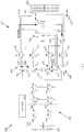
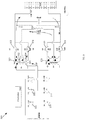
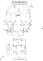
- FIG. 4 One working principle of the DC-AC converter 300 is illustrated in FIG. 4 .
- the controller 344 operates the DC-AC converter 300 to turn one leg of the DC-DC bridge 302 off (e.g., the leg including the third switch (Q3) 312 and the sixth switch (Q6) 318) and to turn on (i.e., close) the ninth switch (Q9) 328 and the tenth switch (Q10) 330.
- return current to the positive side converter 304 is via the negative side converter 306 as shown in FIG. 4 .
- the return current passes through the diodes (D7, D8) of the seventh switch (Q7) 322, the eighth switch (Q8) 324, the secondary winding 323, and the inductor (Lout) 332.
- the seventh switch (Q7) 322 in the first freewheeling-end state of the reactive power mode, the seventh switch (Q7) 322 is turned off (generating a dead band between the seventh switch (Q7) 322 and the second switch (Q2) 310/fourth switch (Q4) 314) and current returns back to the source 301.
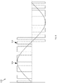
- each pulse 2202 increases the flux 2204 in the transformer to a higher level from the previous pulse, but in an opposite direction, up to a peak of a sine wave.
- the maximum flux build-up occurs at the peak of a sine wave, which is equal to the voltage across the primary winding multiplied by the duty cycle of the pulse 2202.
- Such operation of the converter 300 corresponds to operation as a pure isolated full bridge DC-DC converter.
Landscapes
- Engineering & Computer Science (AREA)
- Power Engineering (AREA)
- Physics & Mathematics (AREA)
- Electromagnetism (AREA)
- Business, Economics & Management (AREA)
- Emergency Management (AREA)
- Dc-Dc Converters (AREA)
- Inverter Devices (AREA)
Claims (8)
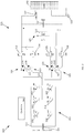
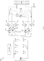
- Ein bidirektionaler DC-AC-Wandler (300), der Folgendes beinhaltet:eine erste Schnittstelle, die dazu konfiguriert ist, an eine Gleichstromquelle gekoppelt zu werden;eine Eingangsbrücke (302), die an die erste Schnittstelle gekoppelt ist;einen Wechselrichterabschnitt (303), der an die Eingangsbrücke gekoppelt ist und Folgendes beinhaltet:einen ersten bidirektionalen Wandler (304), der an die Eingangsbrücke gekoppelt ist;einen zweiten bidirektionalen Wandler (306), der an die Eingangsbrücke gekoppelt ist; undeinen Ausgangsfilter (305), der an den ersten bidirektionalen Wandler und den zweiten bidirektionalen Wandler gekoppelt ist;wobei der bidirektionale DC-AC-Wandler (300) ferner Folgendes beinhaltet:eine zweite Schnittstelle, die an den Ausgangsfilter gekoppelt ist und dazu konfiguriert ist, an eine Last gekoppelt zu werden; undeinen Regler (344), der dazu konfiguriert ist, die Eingangsbrücke zu betreiben, um Gleichstrom aus der Gleichstromquelle abzuziehen und den Wechselrichterabschnitt mit Strom zu versorgen, in einem ersten Betriebsmodus den ersten bidirektionalen Wandler zusammen mit dem Ausgangsfilter zu betreiben, um einen positiven Halbzyklus einer Ausgangsspannungswellenform an der zweiten Schnittstelle zu erzeugen, und in einem zweiten Betriebsmodus den zweiten bidirektionalen Wandler zusammen mit dem Ausgangsfilter zu betreiben, um einen negativen Halbzyklus der Ausgangsspannungswellenform an der zweite Schnittstelle zu erzeugen;wobei der erste bidirektionale Wandler Folgendes beinhaltet:einen ersten Transformator, der eine erste Primärwicklung (321) und eine erste Sekundärwicklung (323) umfasst, wobei die erste Primärwicklung ein erstes Ende und ein zweites Ende, die an die Eingangsbrücke gekoppelt sind, umfasst und die erste Sekundärwicklung ein erstes Ende, das über einen ersten Abschnitt der ersten Sekundärwicklung (323) an einen ersten Mittelabgriff gekoppelt ist, und ein zweites Ende, das über einen zweiten Abschnitt der ersten Sekundärwicklung (323) an den ersten Mittelabgriff gekoppelt ist, umfasst;einen ersten Schalter (322), der zwischen das erste Ende der ersten Sekundärwicklung und die zweite Schnittstelle gekoppelt ist; undeinen zweiten Schalter (324), der zwischen das zweite Ende der ersten Sekundärwicklung und die zweite Schnittstelle gekoppelt ist;wobei der zweite bidirektionale Wandler Folgendes beinhaltet:einen zweiten Transformator, der eine zweite Primärwicklung (327) und eine zweite Sekundärwicklung (329) umfasst, wobei die zweite Primärwicklung ein erstes Ende und ein zweites Ende, die an die Eingangsbrücke gekoppelt sind, umfasst und die zweite Sekundärwicklung ein erstes Ende, das über einen ersten Abschnitt der zweiten Sekundärwicklung an einen zweiten Mittelabgriff gekoppelt ist, und ein zweites Ende, das über einen zweiten Abschnitt der zweiten Sekundärwicklung an den zweiten Mittelabgriff gekoppelt ist, umfasst;einen dritten Schalter (328), der zwischen das erste Ende der zweiten Sekundärwicklung und den Nullleiter gekoppelt ist; undeinen vierten Schalter (330), der zwischen das zweite Ende der zweiten Sekundärwicklung und den Nullleiter gekoppelt ist; undwobei die Eingangsbrücke (302) eine Vielzahl von Schaltern beinhaltet, die an die erste Schnittstelle, den ersten Transformator und den zweiten Transformator gekoppelt sind, undwobei der Regler ferner dazu konfiguriert ist, im ersten Betriebsmodus den zweiten bidirektionalen Wandler zu betreiben, um durch Stromfluss durch den dritten Schalter erzeugten Leistungsfluss in der zweiten Sekundärwicklung mittels durch Stromfluss durch den vierten Schalter erzeugten Leistungsfluss in der zweiten Sekundärwicklung zu unterdrücken, undwobei der Regler ferner dazu konfiguriert ist, im zweiten Betriebsmodus den ersten bidirektionalen Wandler zu betreiben, um durch Stromfluss durch den ersten Schalter erzeugten Leistungsfluss in der ersten Sekundärwicklung mittels durch Stromfluss durch den zweiten Schalter erzeugten Leistungsfluss in der ersten Sekundärwicklung zu unterdrücken.
- Bidirektionaler DC-AC-Wandler gemäß Anspruch 1, wobei der Ausgangsfilter einen Filter, der zwischen den ersten Mittelabgriff und den zweiten Mittelabgriff gekoppelt ist, und einen Ausgangskondensator, der zwischen die zweite Schnittstelle und den Nullleiter gekoppelt ist, beinhaltet.
- Bidirektionaler DC-AC-Wandler gemäß Anspruch 2, wobei die Eingangsbrücke Folgendes beinhaltet:eine Vielzahl von Schaltern, die an die erste Schnittstelle, das erste Ende der ersten Primärwicklung und das zweite Ende der zweiten Primärwicklung gekoppelt sind; undeine gemeinsame Leitung, die an die Vielzahl von Schaltern, das zweite Ende der ersten Primärwicklung und das erste Ende der zweiten Primärwicklung gekoppelt ist.
- Bidirektionaler DC-AC-Wandler gemäß Anspruch 3, wobei die Vielzahl von Schaltern Folgendes beinhaltet:einen fünften Schalter, der zwischen die erste Schnittstelle und das erste Ende der ersten Primärwicklung gekoppelt ist;einen sechsten Schalter, der zwischen die erste Schnittstelle und die gemeinsame Leitung gekoppelt ist; undeinen siebten Schalter, der zwischen die erste Schnittstelle und das zweite Ende der zweiten Primärwicklung gekoppelt ist.
- Bidirektionaler DC-AC-Wandler gemäß Anspruch 4, wobei die Vielzahl von Schaltern ferner Folgendes beinhaltet:einen achten Schalter, der zwischen das erste Ende der ersten Primärwicklung und die Gleichstromquelle gekoppelt ist;einen neunten Schalter, der zwischen die gemeinsame Leitung und die Gleichstromquelle gekoppelt ist; undeinen zehnten Schalter, der zwischen das zweite Ende der zweiten Primärwicklung und die Gleichstromquelle gekoppelt ist.
- Bidirektionaler DC-AC-Wandler gemäß Anspruch 1,
wobei die zweite Schnittstelle ferner dazu konfiguriert ist, an eine Wechselstromquelle gekoppelt zu werden und Eingangswechselstrom von der Wechselstromquelle zu empfangen, und
wobei der Regler ferner dazu konfiguriert ist, den ersten bidirektionalen Wandler zusammen mit dem zweiten bidirektionalen Wandler und der Eingangsbrücke zu betreiben, um die erste Schnittstelle mit von dem Eingangswechselstrom erlangtem Gleichstrom zu versorgen. - Ein Verfahren zum Betreiben eines bidirektionalen DC-AC-Wandlers, das Folgendes beinhaltet: eine erste Schnittstelle, die dazu konfiguriert ist, an eine Gleichstromquelle gekoppelt zu werden, eine Eingangsbrücke, die an die erste Schnittstelle gekoppelt ist, einen Wechselrichterabschnitt, der an die Eingangsbrücke gekoppelt ist, und eine zweite Schnittstelle, die dazu konfiguriert ist, an eine Last gekoppelt zu werden, wobei der Wechselrichterabschnitt einen ersten bidirektionalen Wandler, der an die Eingangsbrücke gekoppelt ist, einen zweiten bidirektionalen Wandler, der an die Eingangsbrücke gekoppelt ist, und einen Ausgangsfilter, der an den ersten bidirektionalen Wandler und den zweiten bidirektionalen Wandler gekoppelt ist, beinhaltet, wobei die zweite Schnittstelle dazu konfiguriert ist, an den Ausgangsfilter gekoppelt zu werden, wobei das Verfahren Folgendes beinhaltet:Abziehen, mittels der Eingangsbrücke über die erste Schnittstelle, von Gleichstrom aus der Gleichstromquelle zu dem Wechselrichterabschnitt;Erzeugen, in einem ersten Betriebsmodus mittels des ersten bidirektionalen Wandlers zusammen mit dem Ausgangsfilter, eines positiven Halbzyklus einer Ausgangsspannungswellenform an der zweiten Schnittstelle; undErzeugen, in einem zweiten Betriebsmodus mittels des zweiten bidirektionalen Wandlers zusammen mit dem Ausgangsfilter, eines negativen Halbzyklus einer Ausgangsspannungswellenform an der zweiten Schnittstelle;wobei der erste bidirektionale Wandler einen ersten Transformator, einen ersten Schalter und einen zweiten Schalter beinhaltet, wobei der erste Transformator eine erste Primärwicklung und eine erste Sekundärwicklung umfasst, wobei die erste Sekundärwicklung ein erstes Ende, das über einen ersten Abschnitt der ersten Sekundärwicklung an den ersten Mittelabgriff gekoppelt ist, und ein zweites Ende, das über einen zweiten Abschnitt der ersten Sekundärwicklung an den ersten Mittelabgriff gekoppelt ist, umfasst, wobei der erste Schalter zwischen das erste Ende der ersten Sekundärwicklung und die zweite Schnittstelle gekoppelt ist und der zweite Schalter zwischen das zweite Ende der ersten Sekundärwicklung und die zweite Schnittstelle gekoppelt ist,wobei der zweite bidirektionale Wandler einen zweiten Transformator, einen dritten Schalter und einen vierten Schalter beinhaltet, wobei der zweite Transformator eine zweite Primärwicklung und eine zweite Sekundärwicklung umfasst, wobei die zweite Sekundärwicklung ein erstes Ende, das über einen ersten Abschnitt der zweiten Sekundärwicklung an einen zweiten Mittelabgriff gekoppelt ist, und ein zweites Ende, das über einen zweiten Abschnitt der zweiten Sekundärwicklung an den zweiten Mittelabgriff gekoppelt ist, umfasst,wobei der dritte Schalter zwischen das erste Ende der zweiten Sekundärwicklung und den Nullleiter gekoppelt ist und der vierte Schalter zwischen das zweite Ende der zweiten Sekundärwicklung und den Nullleiter gekoppelt ist, undwobei die Eingangsbrücke eine Vielzahl von Schaltern beinhaltet, die an die erste Schnittstelle, den ersten Transformator und den zweiten Transformator gekoppelt sind,wobei das Verfahren ferner Folgendes beinhaltet:Betreiben, im ersten Betriebsmodus, des zweiten bidirektionalen Wandlers, um durch Stromfluss durch den dritten Schalter erzeugten Leistungsfluss in der zweiten Sekundärwicklung mittels durch Stromfluss durch den vierten Schalter erzeugten Leistungsfluss in der zweiten Sekundärwicklung zu unterdrücken; undBetreiben, im zweiten Betriebsmodus, des ersten bidirektionalen Wandlers, um durch Stromfluss durch den ersten Schalter erzeugten Leistungsfluss in der ersten Sekundärwicklung mittels durch Stromfluss durch den zweiten Schalter erzeugten Leistungsfluss in der ersten Sekundärwicklung zu unterdrücken.
- Verfahren gemäß Anspruch 7, wobei die zweite Schnittstelle ferner dazu konfiguriert ist, an eine Wechselstromquelle gekoppelt zu werden, und wobei das Verfahren ferner Folgendes beinhaltet:Empfangen von Eingangswechselstrom von einer Wechselstromquelle; undBetreiben des ersten bidirektionalen Wandlers zusammen mit dem zweiten bidirektionalen Wandler und der Eingangsbrücke, um die erste Schnittstelle mit von dem Eingangswechselstrom erlangtem Gleichstrom zu versorgen, um die Gleichstromquelle zu laden.
Applications Claiming Priority (1)
| Application Number | Priority Date | Filing Date | Title |
|---|---|---|---|
| US15/802,614 US10199957B1 (en) | 2017-11-03 | 2017-11-03 | DC-AC bidirectional converter |
Publications (2)
| Publication Number | Publication Date |
|---|---|
| EP3480934A1 EP3480934A1 (de) | 2019-05-08 |
| EP3480934B1 true EP3480934B1 (de) | 2020-12-02 |
Family
ID=64051357
Family Applications (1)
| Application Number | Title | Priority Date | Filing Date |
|---|---|---|---|
| EP18202764.9A Active EP3480934B1 (de) | 2017-11-03 | 2018-10-26 | Bidirektionaler dc-ac-wandler mit zwei richtungen |
Country Status (3)
| Country | Link |
|---|---|
| US (1) | US10199957B1 (de) |
| EP (1) | EP3480934B1 (de) |
| CN (1) | CN109756145B (de) |
Families Citing this family (5)
| Publication number | Priority date | Publication date | Assignee | Title |
|---|---|---|---|---|
| WO2020051288A1 (en) * | 2018-09-07 | 2020-03-12 | The University Of Texas At Austin | Converter having a transformer with secondary central point tap |
| US12237777B2 (en) * | 2021-06-15 | 2025-02-25 | Texas Instruments Incorporated | LLC converter and control |
| CN113541487A (zh) * | 2021-06-28 | 2021-10-22 | 中国船舶重工集团公司第七二三研究所 | 一种级联稳压正弦谐振的高压电源 |
| CN115664248B (zh) * | 2022-12-14 | 2023-03-21 | 惠州市乐亿通科技有限公司 | 双向逆变电路和双向逆变器 |
| CN118074536B (zh) * | 2024-01-24 | 2024-10-01 | 青岛理工大学 | 一种三相高频逆变器的调制方法 |
Family Cites Families (8)
| Publication number | Priority date | Publication date | Assignee | Title |
|---|---|---|---|---|
| JPH1042564A (ja) * | 1996-07-17 | 1998-02-13 | Nippon Telegr & Teleph Corp <Ntt> | Ac−dc変換装置 |
| US20110236591A1 (en) * | 2008-11-28 | 2011-09-29 | General Plasma Inc. | Bipolar rectifier power supply |
| US8466658B2 (en) * | 2009-08-05 | 2013-06-18 | GM Global Technology Operations LLC | Systems and methods for bi-directional energy delivery with galvanic isolation |
| CN101635530B (zh) * | 2009-08-28 | 2011-05-04 | 南京航空航天大学 | 一种单级正激式高频链逆变器 |
| US8288887B2 (en) * | 2009-11-19 | 2012-10-16 | GM Global Technology Operations LLC | Systems and methods for commutating inductor current using a matrix converter |
| CN102364862A (zh) * | 2011-10-09 | 2012-02-29 | 电子科技大学 | Ac/ac变换器 |
| WO2014152948A2 (en) * | 2013-03-14 | 2014-09-25 | Engineered Electric Company | Bidirectional power converter |
| US9685881B2 (en) * | 2015-06-04 | 2017-06-20 | Schneider Electric It Corporation | AC-DC rectifier system |
-
2017
- 2017-11-03 US US15/802,614 patent/US10199957B1/en active Active
-
2018
- 2018-10-26 EP EP18202764.9A patent/EP3480934B1/de active Active
- 2018-11-02 CN CN201811300802.9A patent/CN109756145B/zh active Active
Non-Patent Citations (1)
| Title |
|---|
| None * |
Also Published As
| Publication number | Publication date |
|---|---|
| CN109756145A (zh) | 2019-05-14 |
| EP3480934A1 (de) | 2019-05-08 |
| US10199957B1 (en) | 2019-02-05 |
| CN109756145B (zh) | 2024-03-19 |
Similar Documents
| Publication | Publication Date | Title |
|---|---|---|
| CN106253718B (zh) | Ac-dc整流器系统 | |
| EP3480934B1 (de) | Bidirektionaler dc-ac-wandler mit zwei richtungen | |
| EP3309927B1 (de) | Gleichspannungszwischenkreisausgleicher | |
| US9979313B2 (en) | 3-level power topology | |
| US11157430B2 (en) | DC-DC power converter with four way power conversion | |
| US20170117810A1 (en) | Isolated and efficient rectifier system | |
| US10833601B2 (en) | Multi-level inverter | |
| US11283288B2 (en) | Integrated DC to DC converter UPS topology | |
| US10461575B2 (en) | Multistate PWM command for 3 levels inverters | |
| US11088634B2 (en) | Inverter with AC forward bridge and improved DC/DC topology | |
| CN111262331B (zh) | 用于ups的具有ac开关pfc前端的飞行电池 | |
| US20170237357A1 (en) | Apparatus and method for low frequency power inverter | |
| EP3176936B1 (de) | Verfahren und vorrichtung zur steuerung von dreistufiger vienna-schaltung | |
| CN110556912A (zh) | Ups三电平pfc拓扑电路及其控制方法 | |
| CN113014103B (zh) | 直流对直流电力变换器系统及非暂时性计算机可读介质 |
Legal Events
| Date | Code | Title | Description |
|---|---|---|---|
| PUAI | Public reference made under article 153(3) epc to a published international application that has entered the european phase |
Free format text: ORIGINAL CODE: 0009012 |
|
| STAA | Information on the status of an ep patent application or granted ep patent |
Free format text: STATUS: THE APPLICATION HAS BEEN PUBLISHED |
|
| AK | Designated contracting states |
Kind code of ref document: A1 Designated state(s): AL AT BE BG CH CY CZ DE DK EE ES FI FR GB GR HR HU IE IS IT LI LT LU LV MC MK MT NL NO PL PT RO RS SE SI SK SM TR |
|
| AX | Request for extension of the european patent |
Extension state: BA ME |
|
| STAA | Information on the status of an ep patent application or granted ep patent |
Free format text: STATUS: REQUEST FOR EXAMINATION WAS MADE |
|
| 17P | Request for examination filed |
Effective date: 20191104 |
|
| RBV | Designated contracting states (corrected) |
Designated state(s): AL AT BE BG CH CY CZ DE DK EE ES FI FR GB GR HR HU IE IS IT LI LT LU LV MC MK MT NL NO PL PT RO RS SE SI SK SM TR |
|
| RIC1 | Information provided on ipc code assigned before grant |
Ipc: H02M 7/5395 20060101ALI20200408BHEP Ipc: H02M 7/48 20070101ALI20200408BHEP Ipc: H02M 7/5387 20070101AFI20200408BHEP Ipc: H02M 1/00 20060101ALN20200408BHEP Ipc: H02J 9/06 20060101ALI20200408BHEP Ipc: H02M 7/797 20060101ALN20200408BHEP Ipc: H02M 3/335 20060101ALN20200408BHEP |
|
| RIC1 | Information provided on ipc code assigned before grant |
Ipc: H02M 3/335 20060101ALN20200422BHEP Ipc: H02M 7/48 20070101ALI20200422BHEP Ipc: H02M 7/5395 20060101ALI20200422BHEP Ipc: H02M 7/5387 20070101AFI20200422BHEP Ipc: H02M 7/797 20060101ALN20200422BHEP Ipc: H02M 1/00 20060101ALN20200422BHEP Ipc: H02J 9/06 20060101ALI20200422BHEP |
|
| RIC1 | Information provided on ipc code assigned before grant |
Ipc: H02M 3/335 20060101ALN20200507BHEP Ipc: H02M 7/797 20060101ALN20200507BHEP Ipc: H02M 1/00 20060101ALN20200507BHEP Ipc: H02J 9/06 20060101ALI20200507BHEP Ipc: H02M 7/5387 20070101AFI20200507BHEP Ipc: H02M 7/5395 20060101ALI20200507BHEP Ipc: H02M 7/48 20070101ALI20200507BHEP |
|
| GRAP | Despatch of communication of intention to grant a patent |
Free format text: ORIGINAL CODE: EPIDOSNIGR1 |
|
| STAA | Information on the status of an ep patent application or granted ep patent |
Free format text: STATUS: GRANT OF PATENT IS INTENDED |
|
| RIC1 | Information provided on ipc code assigned before grant |
Ipc: H02M 1/00 20060101ALN20200520BHEP Ipc: H02J 9/06 20060101ALI20200520BHEP Ipc: H02M 7/797 20060101ALN20200520BHEP Ipc: H02M 3/335 20060101ALN20200520BHEP Ipc: H02M 7/5387 20070101AFI20200520BHEP Ipc: H02M 7/5395 20060101ALI20200520BHEP Ipc: H02M 7/48 20070101ALI20200520BHEP |
|
| RIC1 | Information provided on ipc code assigned before grant |
Ipc: H02M 7/5387 20070101AFI20200525BHEP Ipc: H02M 3/335 20060101ALN20200525BHEP Ipc: H02J 9/06 20060101ALI20200525BHEP Ipc: H02M 1/00 20060101ALN20200525BHEP Ipc: H02M 7/48 20070101ALI20200525BHEP Ipc: H02M 7/797 20060101ALN20200525BHEP Ipc: H02M 7/5395 20060101ALI20200525BHEP |
|
| INTG | Intention to grant announced |
Effective date: 20200619 |
|
| GRAS | Grant fee paid |
Free format text: ORIGINAL CODE: EPIDOSNIGR3 |
|
| GRAA | (expected) grant |
Free format text: ORIGINAL CODE: 0009210 |
|
| STAA | Information on the status of an ep patent application or granted ep patent |
Free format text: STATUS: THE PATENT HAS BEEN GRANTED |
|
| AK | Designated contracting states |
Kind code of ref document: B1 Designated state(s): AL AT BE BG CH CY CZ DE DK EE ES FI FR GB GR HR HU IE IS IT LI LT LU LV MC MK MT NL NO PL PT RO RS SE SI SK SM TR |
|
| REG | Reference to a national code |
Ref country code: GB Ref legal event code: FG4D |
|
| REG | Reference to a national code |
Ref country code: AT Ref legal event code: REF Ref document number: 1342013 Country of ref document: AT Kind code of ref document: T Effective date: 20201215 Ref country code: CH Ref legal event code: EP |
|
| REG | Reference to a national code |
Ref country code: IE Ref legal event code: FG4D |
|
| REG | Reference to a national code |
Ref country code: DE Ref legal event code: R096 Ref document number: 602018010371 Country of ref document: DE |
|
| PG25 | Lapsed in a contracting state [announced via postgrant information from national office to epo] |
Ref country code: RS Free format text: LAPSE BECAUSE OF FAILURE TO SUBMIT A TRANSLATION OF THE DESCRIPTION OR TO PAY THE FEE WITHIN THE PRESCRIBED TIME-LIMIT Effective date: 20201202 Ref country code: FI Free format text: LAPSE BECAUSE OF FAILURE TO SUBMIT A TRANSLATION OF THE DESCRIPTION OR TO PAY THE FEE WITHIN THE PRESCRIBED TIME-LIMIT Effective date: 20201202 Ref country code: GR Free format text: LAPSE BECAUSE OF FAILURE TO SUBMIT A TRANSLATION OF THE DESCRIPTION OR TO PAY THE FEE WITHIN THE PRESCRIBED TIME-LIMIT Effective date: 20210303 Ref country code: NO Free format text: LAPSE BECAUSE OF FAILURE TO SUBMIT A TRANSLATION OF THE DESCRIPTION OR TO PAY THE FEE WITHIN THE PRESCRIBED TIME-LIMIT Effective date: 20210302 |
|
| REG | Reference to a national code |
Ref country code: NL Ref legal event code: MP Effective date: 20201202 |
|
| REG | Reference to a national code |
Ref country code: AT Ref legal event code: MK05 Ref document number: 1342013 Country of ref document: AT Kind code of ref document: T Effective date: 20201202 |
|
| PG25 | Lapsed in a contracting state [announced via postgrant information from national office to epo] |
Ref country code: LV Free format text: LAPSE BECAUSE OF FAILURE TO SUBMIT A TRANSLATION OF THE DESCRIPTION OR TO PAY THE FEE WITHIN THE PRESCRIBED TIME-LIMIT Effective date: 20201202 Ref country code: PL Free format text: LAPSE BECAUSE OF FAILURE TO SUBMIT A TRANSLATION OF THE DESCRIPTION OR TO PAY THE FEE WITHIN THE PRESCRIBED TIME-LIMIT Effective date: 20201202 Ref country code: SE Free format text: LAPSE BECAUSE OF FAILURE TO SUBMIT A TRANSLATION OF THE DESCRIPTION OR TO PAY THE FEE WITHIN THE PRESCRIBED TIME-LIMIT Effective date: 20201202 Ref country code: BG Free format text: LAPSE BECAUSE OF FAILURE TO SUBMIT A TRANSLATION OF THE DESCRIPTION OR TO PAY THE FEE WITHIN THE PRESCRIBED TIME-LIMIT Effective date: 20210302 |
|
| PG25 | Lapsed in a contracting state [announced via postgrant information from national office to epo] |
Ref country code: HR Free format text: LAPSE BECAUSE OF FAILURE TO SUBMIT A TRANSLATION OF THE DESCRIPTION OR TO PAY THE FEE WITHIN THE PRESCRIBED TIME-LIMIT Effective date: 20201202 Ref country code: NL Free format text: LAPSE BECAUSE OF FAILURE TO SUBMIT A TRANSLATION OF THE DESCRIPTION OR TO PAY THE FEE WITHIN THE PRESCRIBED TIME-LIMIT Effective date: 20201202 |
|
| REG | Reference to a national code |
Ref country code: LT Ref legal event code: MG9D |
|
| PG25 | Lapsed in a contracting state [announced via postgrant information from national office to epo] |
Ref country code: SK Free format text: LAPSE BECAUSE OF FAILURE TO SUBMIT A TRANSLATION OF THE DESCRIPTION OR TO PAY THE FEE WITHIN THE PRESCRIBED TIME-LIMIT Effective date: 20201202 Ref country code: SM Free format text: LAPSE BECAUSE OF FAILURE TO SUBMIT A TRANSLATION OF THE DESCRIPTION OR TO PAY THE FEE WITHIN THE PRESCRIBED TIME-LIMIT Effective date: 20201202 Ref country code: EE Free format text: LAPSE BECAUSE OF FAILURE TO SUBMIT A TRANSLATION OF THE DESCRIPTION OR TO PAY THE FEE WITHIN THE PRESCRIBED TIME-LIMIT Effective date: 20201202 Ref country code: CZ Free format text: LAPSE BECAUSE OF FAILURE TO SUBMIT A TRANSLATION OF THE DESCRIPTION OR TO PAY THE FEE WITHIN THE PRESCRIBED TIME-LIMIT Effective date: 20201202 Ref country code: RO Free format text: LAPSE BECAUSE OF FAILURE TO SUBMIT A TRANSLATION OF THE DESCRIPTION OR TO PAY THE FEE WITHIN THE PRESCRIBED TIME-LIMIT Effective date: 20201202 Ref country code: PT Free format text: LAPSE BECAUSE OF FAILURE TO SUBMIT A TRANSLATION OF THE DESCRIPTION OR TO PAY THE FEE WITHIN THE PRESCRIBED TIME-LIMIT Effective date: 20210405 Ref country code: LT Free format text: LAPSE BECAUSE OF FAILURE TO SUBMIT A TRANSLATION OF THE DESCRIPTION OR TO PAY THE FEE WITHIN THE PRESCRIBED TIME-LIMIT Effective date: 20201202 |
|
| PG25 | Lapsed in a contracting state [announced via postgrant information from national office to epo] |
Ref country code: AT Free format text: LAPSE BECAUSE OF FAILURE TO SUBMIT A TRANSLATION OF THE DESCRIPTION OR TO PAY THE FEE WITHIN THE PRESCRIBED TIME-LIMIT Effective date: 20201202 |
|
| REG | Reference to a national code |
Ref country code: DE Ref legal event code: R097 Ref document number: 602018010371 Country of ref document: DE |
|
| PG25 | Lapsed in a contracting state [announced via postgrant information from national office to epo] |
Ref country code: IS Free format text: LAPSE BECAUSE OF FAILURE TO SUBMIT A TRANSLATION OF THE DESCRIPTION OR TO PAY THE FEE WITHIN THE PRESCRIBED TIME-LIMIT Effective date: 20210402 |
|
| PLBE | No opposition filed within time limit |
Free format text: ORIGINAL CODE: 0009261 |
|
| STAA | Information on the status of an ep patent application or granted ep patent |
Free format text: STATUS: NO OPPOSITION FILED WITHIN TIME LIMIT |
|
| PG25 | Lapsed in a contracting state [announced via postgrant information from national office to epo] |
Ref country code: IT Free format text: LAPSE BECAUSE OF FAILURE TO SUBMIT A TRANSLATION OF THE DESCRIPTION OR TO PAY THE FEE WITHIN THE PRESCRIBED TIME-LIMIT Effective date: 20201202 Ref country code: AL Free format text: LAPSE BECAUSE OF FAILURE TO SUBMIT A TRANSLATION OF THE DESCRIPTION OR TO PAY THE FEE WITHIN THE PRESCRIBED TIME-LIMIT Effective date: 20201202 |
|
| 26N | No opposition filed |
Effective date: 20210903 |
|
| PG25 | Lapsed in a contracting state [announced via postgrant information from national office to epo] |
Ref country code: SI Free format text: LAPSE BECAUSE OF FAILURE TO SUBMIT A TRANSLATION OF THE DESCRIPTION OR TO PAY THE FEE WITHIN THE PRESCRIBED TIME-LIMIT Effective date: 20201202 Ref country code: DK Free format text: LAPSE BECAUSE OF FAILURE TO SUBMIT A TRANSLATION OF THE DESCRIPTION OR TO PAY THE FEE WITHIN THE PRESCRIBED TIME-LIMIT Effective date: 20201202 |
|
| PG25 | Lapsed in a contracting state [announced via postgrant information from national office to epo] |
Ref country code: ES Free format text: LAPSE BECAUSE OF FAILURE TO SUBMIT A TRANSLATION OF THE DESCRIPTION OR TO PAY THE FEE WITHIN THE PRESCRIBED TIME-LIMIT Effective date: 20201202 |
|
| REG | Reference to a national code |
Ref country code: CH Ref legal event code: PL |
|
| PG25 | Lapsed in a contracting state [announced via postgrant information from national office to epo] |
Ref country code: IS Free format text: LAPSE BECAUSE OF FAILURE TO SUBMIT A TRANSLATION OF THE DESCRIPTION OR TO PAY THE FEE WITHIN THE PRESCRIBED TIME-LIMIT Effective date: 20210402 |
|
| REG | Reference to a national code |
Ref country code: BE Ref legal event code: MM Effective date: 20211031 |
|
| PG25 | Lapsed in a contracting state [announced via postgrant information from national office to epo] |
Ref country code: MC Free format text: LAPSE BECAUSE OF FAILURE TO SUBMIT A TRANSLATION OF THE DESCRIPTION OR TO PAY THE FEE WITHIN THE PRESCRIBED TIME-LIMIT Effective date: 20201202 |
|
| PG25 | Lapsed in a contracting state [announced via postgrant information from national office to epo] |
Ref country code: LU Free format text: LAPSE BECAUSE OF NON-PAYMENT OF DUE FEES Effective date: 20211026 Ref country code: BE Free format text: LAPSE BECAUSE OF NON-PAYMENT OF DUE FEES Effective date: 20211031 |
|
| PG25 | Lapsed in a contracting state [announced via postgrant information from national office to epo] |
Ref country code: LI Free format text: LAPSE BECAUSE OF NON-PAYMENT OF DUE FEES Effective date: 20211031 Ref country code: CH Free format text: LAPSE BECAUSE OF NON-PAYMENT OF DUE FEES Effective date: 20211031 |
|
| PG25 | Lapsed in a contracting state [announced via postgrant information from national office to epo] |
Ref country code: IE Free format text: LAPSE BECAUSE OF NON-PAYMENT OF DUE FEES Effective date: 20211026 |
|
| PG25 | Lapsed in a contracting state [announced via postgrant information from national office to epo] |
Ref country code: CY Free format text: LAPSE BECAUSE OF FAILURE TO SUBMIT A TRANSLATION OF THE DESCRIPTION OR TO PAY THE FEE WITHIN THE PRESCRIBED TIME-LIMIT Effective date: 20201202 |
|
| PG25 | Lapsed in a contracting state [announced via postgrant information from national office to epo] |
Ref country code: HU Free format text: LAPSE BECAUSE OF FAILURE TO SUBMIT A TRANSLATION OF THE DESCRIPTION OR TO PAY THE FEE WITHIN THE PRESCRIBED TIME-LIMIT; INVALID AB INITIO Effective date: 20181026 |
|
| PG25 | Lapsed in a contracting state [announced via postgrant information from national office to epo] |
Ref country code: MK Free format text: LAPSE BECAUSE OF FAILURE TO SUBMIT A TRANSLATION OF THE DESCRIPTION OR TO PAY THE FEE WITHIN THE PRESCRIBED TIME-LIMIT Effective date: 20201202 |
|
| PG25 | Lapsed in a contracting state [announced via postgrant information from national office to epo] |
Ref country code: MT Free format text: LAPSE BECAUSE OF FAILURE TO SUBMIT A TRANSLATION OF THE DESCRIPTION OR TO PAY THE FEE WITHIN THE PRESCRIBED TIME-LIMIT Effective date: 20201202 |
|
| PG25 | Lapsed in a contracting state [announced via postgrant information from national office to epo] |
Ref country code: TR Free format text: LAPSE BECAUSE OF FAILURE TO SUBMIT A TRANSLATION OF THE DESCRIPTION OR TO PAY THE FEE WITHIN THE PRESCRIBED TIME-LIMIT Effective date: 20201202 |
|
| PGFP | Annual fee paid to national office [announced via postgrant information from national office to epo] |
Ref country code: DE Payment date: 20251028 Year of fee payment: 8 |
|
| PGFP | Annual fee paid to national office [announced via postgrant information from national office to epo] |
Ref country code: GB Payment date: 20251030 Year of fee payment: 8 |
|
| PGFP | Annual fee paid to national office [announced via postgrant information from national office to epo] |
Ref country code: FR Payment date: 20251030 Year of fee payment: 8 |