EP3480973A1 - Réseau de fibre optique gigabit bidirectionnel à longueurs d'ondes multiples - Google Patents
Réseau de fibre optique gigabit bidirectionnel à longueurs d'ondes multiples Download PDFInfo
- Publication number
- EP3480973A1 EP3480973A1 EP18202791.2A EP18202791A EP3480973A1 EP 3480973 A1 EP3480973 A1 EP 3480973A1 EP 18202791 A EP18202791 A EP 18202791A EP 3480973 A1 EP3480973 A1 EP 3480973A1
- Authority
- EP
- European Patent Office
- Prior art keywords
- wavelength
- fiber
- transceiver
- laser
- dual
- Prior art date
- Legal status (The legal status is an assumption and is not a legal conclusion. Google has not performed a legal analysis and makes no representation as to the accuracy of the status listed.)
- Granted
Links
Images


Classifications
-
- H—ELECTRICITY
- H04—ELECTRIC COMMUNICATION TECHNIQUE
- H04B—TRANSMISSION
- H04B10/00—Transmission systems employing electromagnetic waves other than radio-waves, e.g. infrared, visible or ultraviolet light, or employing corpuscular radiation, e.g. quantum communication
- H04B10/25—Arrangements specific to fibre transmission
- H04B10/2589—Bidirectional transmission
-
- H—ELECTRICITY
- H04—ELECTRIC COMMUNICATION TECHNIQUE
- H04J—MULTIPLEX COMMUNICATION
- H04J14/00—Optical multiplex systems
- H04J14/02—Wavelength-division multiplex systems
- H04J14/0278—WDM optical network architectures
- H04J14/028—WDM bus architectures
-
- H—ELECTRICITY
- H04—ELECTRIC COMMUNICATION TECHNIQUE
- H04B—TRANSMISSION
- H04B10/00—Transmission systems employing electromagnetic waves other than radio-waves, e.g. infrared, visible or ultraviolet light, or employing corpuscular radiation, e.g. quantum communication
- H04B10/25—Arrangements specific to fibre transmission
- H04B10/2581—Multimode transmission
-
- H—ELECTRICITY
- H04—ELECTRIC COMMUNICATION TECHNIQUE
- H04B—TRANSMISSION
- H04B10/00—Transmission systems employing electromagnetic waves other than radio-waves, e.g. infrared, visible or ultraviolet light, or employing corpuscular radiation, e.g. quantum communication
- H04B10/27—Arrangements for networking
- H04B10/278—Bus-type networks
-
- H—ELECTRICITY
- H04—ELECTRIC COMMUNICATION TECHNIQUE
- H04B—TRANSMISSION
- H04B10/00—Transmission systems employing electromagnetic waves other than radio-waves, e.g. infrared, visible or ultraviolet light, or employing corpuscular radiation, e.g. quantum communication
- H04B10/29—Repeaters
- H04B10/291—Repeaters in which processing or amplification is carried out without conversion of the main signal from optical form
-
- H—ELECTRICITY
- H04—ELECTRIC COMMUNICATION TECHNIQUE
- H04B—TRANSMISSION
- H04B10/00—Transmission systems employing electromagnetic waves other than radio-waves, e.g. infrared, visible or ultraviolet light, or employing corpuscular radiation, e.g. quantum communication
- H04B10/40—Transceivers
-
- H—ELECTRICITY
- H04—ELECTRIC COMMUNICATION TECHNIQUE
- H04B—TRANSMISSION
- H04B10/00—Transmission systems employing electromagnetic waves other than radio-waves, e.g. infrared, visible or ultraviolet light, or employing corpuscular radiation, e.g. quantum communication
- H04B10/50—Transmitters
- H04B10/501—Structural aspects
- H04B10/503—Laser transmitters
-
- H—ELECTRICITY
- H04—ELECTRIC COMMUNICATION TECHNIQUE
- H04B—TRANSMISSION
- H04B10/00—Transmission systems employing electromagnetic waves other than radio-waves, e.g. infrared, visible or ultraviolet light, or employing corpuscular radiation, e.g. quantum communication
- H04B10/50—Transmitters
- H04B10/501—Structural aspects
- H04B10/506—Multiwavelength transmitters
-
- H—ELECTRICITY
- H04—ELECTRIC COMMUNICATION TECHNIQUE
- H04J—MULTIPLEX COMMUNICATION
- H04J14/00—Optical multiplex systems
- H04J14/02—Wavelength-division multiplex systems
-
- H—ELECTRICITY
- H04—ELECTRIC COMMUNICATION TECHNIQUE
- H04J—MULTIPLEX COMMUNICATION
- H04J14/00—Optical multiplex systems
- H04J14/02—Wavelength-division multiplex systems
- H04J14/0226—Fixed carrier allocation, e.g. according to service
-
- H—ELECTRICITY
- H04—ELECTRIC COMMUNICATION TECHNIQUE
- H04J—MULTIPLEX COMMUNICATION
- H04J14/00—Optical multiplex systems
- H04J14/02—Wavelength-division multiplex systems
- H04J14/0227—Operation, administration, maintenance or provisioning [OAMP] of WDM networks, e.g. media access, routing or wavelength allocation
- H04J14/0241—Wavelength allocation for communications one-to-one, e.g. unicasting wavelengths
-
- G—PHYSICS
- G02—OPTICS
- G02B—OPTICAL ELEMENTS, SYSTEMS OR APPARATUS
- G02B6/00—Light guides; Structural details of arrangements comprising light guides and other optical elements, e.g. couplings
- G02B6/24—Coupling light guides
- G02B6/26—Optical coupling means
-
- G—PHYSICS
- G02—OPTICS
- G02B—OPTICAL ELEMENTS, SYSTEMS OR APPARATUS
- G02B6/00—Light guides; Structural details of arrangements comprising light guides and other optical elements, e.g. couplings
- G02B6/24—Coupling light guides
- G02B6/42—Coupling light guides with opto-electronic elements
- G02B6/4201—Packages, e.g. shape, construction, internal or external details
- G02B6/4246—Bidirectionally operating package structures
Definitions
- the technology disclosed herein generally relates to fiber optical networks that enable communication between electrical components.
- An optical fiber is a cylindrical dielectric waveguide that transmits light along its axis.
- the fiber consists of a transparent core surrounded by a transparent cladding layer (hereinafter "cladding"), both of which are made of dielectric materials.
- cladding transparent cladding layer
- Light is kept in the core by the phenomenon of total internal reflection.
- the refractive index of the core is greater than that of the cladding.
- the boundary between the core and cladding may either be abrupt, as in step-index fiber, or gradual, as in graded-index fiber.
- Optical fibers can be made of glass or plastic.
- Optical networking using plastic optical fiber has advantages over copper wiring in weight, size, bandwidth, power, and electromagnetic immunity.
- POF has advantages over glass optical fiber (GOF) in ease of handling, installation and maintenance.
- POF core material can range from acrylate to perfluorinated polymer.
- POF index profile can range from step index to graded index.
- POF geometry can range from single core to multi-core.
- POF core can accommodate single mode (a single optical path in a very small fiber core) to multi-mode (multiple optical paths in a larger fiber core).
- Using POF may result in appreciable weight savings. The weight savings may be significant for networks onboard vehicles, such as airplanes, where the weight savings may result in reduced fuel consumption and lower emissions.
- LRUs line replaceable units
- a number of LRUs in the forward section of a vehicle e.g., an airplane
- Connecting each LRU to every other LRU could result in an unreasonably large number of connections.
- many of the connections between LRUs may be long, resulting in optical losses.
- Fiber optic networks have the advantages of higher speed, lower weight and electromagnetic interference immunity over copper networks.
- Many models of commercial airplanes have fiber optic networks for size, weight and power reduction.
- the large number of glass optical fiber (GOF) cables in the airplane is an important factor contributing to high manufacturing cost.
- GOG glass optical fiber
- a typical solution to reduce fiber count is to use a wavelength division multiplexing (WDM) system.
- WDM wavelength division multiplexing
- typical WDM systems are not compatible with multimode optical fiber currently used onboard commercial transport aircraft.
- Typical WDM components are designed for use with single-mode fiber.
- Single-mode fiber has a diameter smaller than 10 microns and therefore is very sensitive to dust, contamination, and misalignment from airplane vibration and shock.
- WDM components such as multiplexing and demultiplexing array waveguide gratings (AWG) are expensive and not proven for use in harsh avionic environments.
- the subject matter disclosed in some detail below is directed to a bidirectional, multi-wavelength fiber optical network that enables communication between electrical components (such as line replaceable units) at high data transmission rates (e.g., greater than 1 Gbits/sec).
- the proposed fiber optical network in accordance with some embodiments comprises a single optical fiber (plastic or glass) capable of transmitting data at rates faster than 1 Gbits/sec.
- a plastic optical fiber will be referred to herein as a "gigabit plastic optical fiber" (GbPOF).
- GbPOF gigabit plastic optical fiber
- Gigabit plastic optical fiber is made of ductile perfluorinated polymer and it does not break during tight cable bending.
- GbPOF has a 55-micron core diameter and a 500-micron cladding diameter.
- GbGOF gigabit glass optical fiber
- OM4 multimode glass optical fiber with a 50-micron core diameter and a 125-micron cladding diameter. This GbGOF has bandwidth for 10 Gbits/sec over distances up to 400 meters.
- a multi-mode GbPOF with the same core diameter is more imperfect with long random polymer chains in spaghetti shapes. These polymer chains create strong forward mode coupling and result in less reflected light that can interfere with the laser source.
- the strong mode coupling in a POF core also reduces the coherency of the laser source and results in minimal modal interference along the fiber length.
- the optical network proposed herein solves the problems of existing WDM systems.
- the proposed optical network comprises of the following elements and characteristics: (1) the laser source can be a single-mode distributed feedback laser, a multi-mode Fabry-Perot laser, or a vertical cavity surface-emitting laser; (2) multiple wavelengths flowing bidirectionally and simultaneously with each wavelength serve a separate communication function, e.g., control data, sensing data, health status data, configuration data, etc.; (3) a single-fiber multi-mode GbPOF or GbGOF link; (4) high-directional and mode-independent GOF couplers between multiple laser sources and the single-fiber GbPOF or GbGOF link; (5) angle/polished connectors between the GOF couplers and the GbPOF or GbGOF link; and (6) angle/polished connectors are not required for connecting segments along the GbPOF or GbGOF link, i.e., flat polish is sufficient.
- the number of fiber cables extending from the forward section to the aft section of the airplane can be reduced by a factor of eight or more by substituting one GbPOF or GbGOF for eight or more POF or GOF.
- the optical network proposed herein reduces multiple fiber optic links to a single GbPOF or GbGOF link for full-duplex or half-duplex bidirectional data communication between multiple LRUs onboard the airplane.
- the optical network uses low-cost, high-performance small form factor pluggable (SFP) bidirectional optical transceivers at the wavelength ranges where the optical losses of the GbPOF are very low if not minimal.
- SFP small form factor pluggable
- the optical network proposed herein uses GOF couplers having low optical reflection to reduce the optical signal reflected from the adjacent bidirectional transceiver. Ultra-low-reflection (or high optical return loss) connectors are used to connect the GbPOF to the outputs of the GOF couplers.
- bidirectional fiber optical network that transmits and receives light of multiple wavelengths by way of a single gigabit plastic or gigabit glass optical fiber for use in the avionics system of an airplane will be described in some detail below, one or more of those embodiments may be characterized by one or more of the following aspects.
- a data transmission system comprising: an optical cable comprising a gigabit optical fiber; and first through fourth transceivers each comprising an optical filter, a laser disposed to transmit light through the optical filter, and a photodetector disposed to receive light reflected by the optical filter, wherein: the laser and photodetector of the first transceiver are respectively optically coupled to the photodetector and laser of the second transceiver, and the laser and photodetector of the third transceiver are respectively optically coupled to the photodetector and laser of the fourth transceiver by way of the gigabit optical fiber; the laser of the first transceiver emits light having a first wavelength, the laser of the second transceiver emits light having a second wavelength, the laser of the third transceiver emits light having a third wavelength, and the laser of the fourth transceiver emits light having a fourth wavelength; and the optical filter of the first and second transceivers passes light
- the data transmission system described in the preceding paragraph may further comprise: fifth through eighth transceivers each comprising an optical filter, a laser disposed to transmit light through the optical filter, and a photodetector disposed to receive light reflected by the optical filter, wherein: the laser and photodetector of the fifth transceiver are respectively optically coupled to the photodetector and laser of the sixth transceiver, and the laser and photodetector of the seventh transceiver are respectively optically coupled to the photodetector and laser of the eighth transceiver by way of the gigabit optical fiber; the laser of the fifth transceiver emits light having a fifth wavelength, the laser of the sixth transceiver emits light having a sixth wavelength, the laser of the seventh transceiver emits light having a seventh wavelength, and the laser of the eighth transceiver emits light having an eighth wavelength; and the optical filter of the fifth and sixth transceivers passes light having the fifth wavelength and reflects light having the sixth wavelength, and the optical filter of the
- This data transmission system further comprises: a first glass optical fiber coupler that optically couples the laser and photodetector of each of the first, third, fifth and seventh transceivers to one end of the gigabit optical fiber; and a second glass optical fiber coupler that optically couples the laser and photodetector of each of the second, fourth, sixth and eighth transceivers to another end of the gigabit optical fiber.
- the first through eighth wavelengths are in a wavelength range from 750 to 1600 nm.
- the first wavelength is 1270 nm
- the second wavelength is 1330 nm
- the third wavelength is 850 nm
- the fourth wavelength is 880 nm
- the fifth wavelength is 780 nm
- the sixth wavelength is 980 nm
- the seventh wavelength is 1200 nm
- the eighth wavelength is 1230 nm.
- each optical filter of the first through eighth transceivers is a wavelength-selective bandpass filter
- each of the first through eighth transceivers is a dual-wavelength single-fiber bidirectional transceiver.
- Another aspect of the subject matter disclosed in detail below is a method for enabling bidirectional full-duplex data transmission between first and second sets of line replaceable units, comprising: (a) equipping each line replaceable unit with a dual-wavelength single-fiber bidirectional transceiver; (b) optically coupling single fibers of the dual-wavelength single-fiber bidirectional transceivers of the first set of line replaceable units to one end of an optical cable that comprises a gigabit optical fiber; and (c) optically coupling single fibers of the dual-wavelength single-fiber bidirectional transceivers of the second set of line replaceable units to another end of the optical cable, wherein the first set of line replaceable units includes at least two line replaceable units, and the number of line replaceable units in the second set is the same as the number of line replaceable units in the first set.
- the single fibers are made of glass and step (b) comprises: coupling the single fibers of the dual-wavelength single-fiber bidirectional transceivers of the first set of line replaceable units into a first glass optical fiber; and connecting one end of the first glass optical fiber to one end of the gigabit optical fiber.
- the first set of line replaceable units comprises a first line replaceable unit
- the second set of line replaceable units comprises a second line replaceable unit
- step (a) comprises: equipping the first line replaceable unit with a first dual-wavelength single-fiber bidirectional transceiver that emits light having a first wavelength and detects light having a second wavelength; and equipping the second line replaceable unit with a second dual-wavelength single-fiber bidirectional transceiver that emits light having the second wavelength and detects light having the first wavelength.
- a further aspect of the subject matter disclosed in detail below is a data communications system, comprising: first and second pluralities of electrical devices configured for sending and receiving electrical signals representing data; a first plurality of dual-wavelength single-fiber bidirectional transceivers, each dual-wavelength single-fiber bidirectional transceiver of the first plurality comprising a respective transmit circuit that converts electrical signals received from a respective one of the first plurality of electrical devices into optical signals and a respective receive circuit that converts optical signals into electrical signals to be sent to the respective one of the first plurality of electrical devices; a second plurality of dual-wavelength single-fiber bidirectional transceiver, each dual-wavelength single-fiber bidirectional transceiver of the second plurality comprising a respective transmit circuit that converts electrical signals received from a respective one of the second plurality of electrical devices into optical signals and a respective receive circuit that converts optical signals into electrical signals to be sent to the respective one of the second plurality of electrical devices; a first glass optical fiber coupler optically coupled to a single fiber of each of
- the first plurality of electronic devices are line replaceable units located in a forward section of an airplane and the second plurality of electronic devices are line replaceable units located in an aft section of the airplane.
- a first dual-wavelength single-fiber bidirectional transceiver of the first plurality emits light having a first wavelength and detects light having a second wavelength; a second dual-wavelength single-fiber bidirectional transceiver of the second plurality emits light having the second wavelength and detects light having the first wavelength; a third dual-wavelength single-fiber bidirectional transceiver of the first plurality emits light having a third wavelength and detects light having a fourth wavelength; a fourth dual-wavelength single-fiber bidirectional transceiver of the second plurality emits light having the fourth wavelength and detects light having the third wavelength; a fifth dual-wavelength single-fiber bidirectional transceiver of the first plurality emits light having a fifth wavelength and detects light having a sixth wavelength; a sixth dual-wavelength single-fiber bidirectional transceiver of the second plurality emits light having the sixth wavelength and detects light having the fifth wavelength; a seventh dual-wavelength single-fiber bidirectional transceiver of the first plurality emits light having
- the first wavelength is 1270 nm
- the second wavelength is 1330 nm
- the third wavelength is 850 nm
- the fourth wavelength is 880 nm
- the fifth wavelength is 780 nm
- the sixth wavelength is 980 nm
- the seventh wavelength is 1200 nm
- the eighth wavelength is 1230 nm.
- a fiber optical network for enabling optical communication between line replaceable units on an airplane at high data transmission rates (e.g., greater than 1 Gbits/sec) will be described in detail below for the purpose of illustration.
- implementation of the fiber optical networks disclosed herein is not limited solely to the environment of an airplane, but rather may be utilized in fiber optical networks onboard other types of vehicles or other types of fiber optical networks (e.g., long-distance terrestrial, data center and fiber-to-the-home/office applications).
- GbPOF long-distance terrestrial, data center and fiber-to-the-home/office applications.
- alternative embodiments may employ GbGOF.
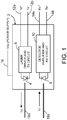
- FIG. 1 is a diagram identifying some features of a dual-fiber bidirectional transceiver design in which the transceiver transmits and receives light of the same wavelength.
- the term "wavelength" in the context of coherent laser light means the center wavelength of laser light having a narrow bandwidth.
- the transceiver is a single-wavelength dual-fiber bidirectional transceiver 2 comprising a laser 4 and a photodetector 8.
- the laser 4 is driven to emit light of a wavelength ⁇ 1 by a laser driver and transmit circuit 6 in response to receipt of differential transmit signals Tx + and Tx - from an associated line replaceable unit (not shown) via transmit electrical signal lines 12a and 12b respectively.
- the laser driver and transmit circuit 6 comprises electrical circuitry that converts those electrical differential signals to electrical digital signals representing the data to be transmitted by the laser 4.
- the photodetector 8 receives light of wavelength ⁇ 1 and converts that detected light into electrical digital signals which are provided to a detector amplifier and receive circuit 10.
- the detector amplifier and receive circuit 10 in turn comprises electrical circuitry that converts those electrical digital signals to electrical differential receive signals Rx + and Rx - representing the data received.
- the electrical differential receive signals Rx + and Rx - are transmitted to other circuitry in the line replaceable unit via receive electrical signal lines 14a and 14b respectively.
- the single-wavelength dual-fiber bidirectional transceiver 2 receives electrical power having a voltage V cc via transceiver power supply line 16.
- the laser 4 is optically coupled to a glass optical fiber 18a, while the photodetector 8 is optically coupled to a glass optical fiber 18b.
- Both glass optical fibers 18a and 18b typically have cores made of the same material having an index of refraction selected to minimize the optical loss for any light of wavelength ⁇ 1 being transmitted along the length of the fiber.
- FIG. 2 is a diagram identifying some features of a bidirectional full-duplex data transmission system 30 comprising one pair of dual-fiber bidirectional transceivers 2a and 2b that each transmit and receive light of the same wavelength, each of the single-wavelength dual-fiber bidirectional transceivers 2a and 2b having the same components as the components of the single-wavelength dual-fiber bidirectional transceiver 2 depicted in FIG. 1 .
- the laser 4 of the single-wavelength dual-fiber bidirectional transceiver 2a is optically coupled to emit light toward the photodetector 8 of the single-wavelength dual-fiber bidirectional transceiver 2b via an optical cable 32 comprising a glass optical fiber 18a, a connector 22a, a gigabit plastic optical fiber 24a, a connector 22b and a glass optical fiber 18c connected in series.
- the laser 4 of the single-wavelength dual-fiber bidirectional transceiver 2b is optically coupled to emit light toward to the photodetector 8 of the single-wavelength dual-fiber bidirectional transceiver 2a via an optical cable 34 comprising a glass optical fiber 18d, a connector 22c, a gigabit plastic optical fiber 24b, a connector 22d and a glass optical fiber 18b connected in series.
- Both single-wavelength dual-fiber bidirectional transceivers 2a and 2b transmit and receive light having a wavelength ⁇ 1 .
- the optical cables 32 and 34 may be identical in construction.
- the inclusion of gigabit plastic optical fibers 24a and 24b enables bidirectional full-duplex data transmission between single-wavelength dual-fiber bidirectional transceivers 2a and 2b at a high data rate (>1 Gbits/sec).
- FIG. 3 is a diagram identifying components of a known bidirectional full-duplex data transmission system 40 having eight full-duplex glass fiber optical cables 42a-42h optically coupling the transceivers of one set of line replaceable units 44 (hereinafter "LRU set 44") to the transceivers of another set of line replaceable units 46 (hereinafter "LRU set 46").
- LRU set 44 may be disposed in a forward section of an airplane while LRU set 46 is disposed in an aft section of the airplane.
- the LRU set 44 comprises four LRUs (respectively designated LRU#1, LRU#3, LRU#5 and LRU#7), whereas the LRU set 46 comprises four LRUs (respectively designated LRU#2, LRU#4, LRU#6 and LRU#8).
- Each of the eight LRUs incorporates a respective dual-fiber transceiver (respectively designated Trx#1 through Trx#8).
- the LRU set 44 comprises four dual-fiber transceivers (respectively designated Trx#1, Trx#3, Trx#5 and Trx#7), whereas the LRU set 46 comprises four dual-fiber transceivers (respectively designated Trx#2, Trx#4, Trx#6 and Trx#8).
- the transceiver Trx#1 is optically coupled to the transceiver Trx#2 via glass optical fiber cables 42a and 42b to enable full-duplex communication between transceivers Trx#1 and Trx#2.
- Transceivers Trx#1 and Trx#2 are configured so that they transmit and receive light having a wavelength ⁇ 1 .
- the transceiver Trx#3 is optically coupled to the transceiver Trx#4 via glass optical fiber cables 42c and 42d to enable full-duplex communication between transceivers Trx#3 and Trx#4.
- Transceivers Trx#3 and Trx#4 are configured so that they transmit and receive light having a wavelength ⁇ 2 .
- the transceiver Trx#5 is optically coupled to the transceiver Trx#6 via glass optical fiber cables 42e and 42f to enable full-duplex communication between transceivers Trx#5 and Trx#6.
- Transceivers Trx#5 and Trx#6 are configured so that they transmit and receive light having a wavelength ⁇ 3 .
- the transceiver Trx#7 is optically coupled to the transceiver Trx#8 via glass optical fiber cables 42g and 42h to enable full-duplex communication between transceivers Trx#7 and Trx#8.
- Transceivers Trx#7 and Trx#8 are configured so that they transmit and receive light having a wavelength ⁇ 4 .
- Each of the dual-fiber transceivers is of the type depicted in FIG. 1 . In the system shown in FIG. 3 , wavelengths ⁇ 1 to ⁇ 4 can be different or equal to each other.
- the bidirectional full-duplex data transmission system 40 depicted in FIG. 3 has eight full-duplex glass optical fiber cables 42a-42h cables to be routed inside the airplane's cable plant.
- the technological improvement that is the subject of this disclosure provides the design for a fiber optical network which comprises a single gigabit plastic optical fiber cable for optical coupling one set of four bidirectional transceivers to another set of four bidirectional transceivers, thereby reducing the number of cables from eight to one single fiber optical cable running a length of the airplane from a front section to an aft section.
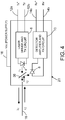
- FIG. 4 is a diagram identifying some features of a single-fiber full-duplex bidirectional transceiver design in which the dual-wavelength single-fiber bidirectional transceiver 20 transmits light having a first wavelength ⁇ 1 and receives light having a second wavelength ⁇ 2 different than the first wavelength ⁇ 1 via the same glass optical fiber 18.
- the dual-wavelength single-fiber bidirectional transceiver 20 comprises a laser 4 and a photodetector 8.
- the laser 4 is driven to emit light of a wavelength ⁇ 1 by a laser driver and transmit circuit 6 in response to receipt of differential transmit signals Tx + and Tx - from an associated line replaceable unit (not shown) via transmit electrical signal lines 12a and 12b respectively.
- the laser drive and transmit circuit 6 comprises electrical circuitry that converts those electrical differential signals to electrical digital signals representing the data to be transmitted by the laser 4.
- the photodetector 8 receives light of wavelength ⁇ 2 and converts that detected light into electrical digital signals which are provided to a detector amplifier and receive circuit 10.
- the detector amplifier and receive circuit 10 in turn comprises electrical circuitry that converts those electrical digital signals to electrical differential receive signals Rx + and Rx - representing the data received.
- the electrical differential receive signals Rx + and Rx - are transmitted to other circuitry in the line replaceable unit via receive electrical signal lines 14a and 14b respectively.
- the dual-wavelength single-fiber bidirectional transceiver 20 depicted in FIG. 4 is capable of single-fiber operation because it is equipped in its optical front end with a wavelength-division multiplexing (WDM) filter 36 (hereinafter “WDM filter 36") which passes the optical signal from the laser 4 at one wavelength ⁇ 1 and reflects the received optical signal at a different wavelength ⁇ 2 toward the photodetector 8.
- WDM filter 36 wavelength-division multiplexing
- the WDM filter 36 inside of the dual-wavelength single-fiber bidirectional transceiver 20 is a wavelength-selective bandpass filter designed in accordance with a high cross-talk isolation technique. Use of such isolation ensures that the optical signal from the local laser 4 is not detected by the receiver in the same bidirectional transceiver.
- FIG. 5 is a diagram identifying some features of a bidirectional full-duplex data transmission system 50 comprising one pair of dual-wavelength single-fiber bidirectional transceivers 20a and 20b, each dual-wavelength single-fiber bidirectional transceiver 20a and 20b being of the type depicted in FIG. 4 .
- the laser 4 of the dual-wavelength single-fiber bidirectional transceiver 20a is optically coupled to emit light toward the photodetector 8 of the dual-wavelength single-fiber bidirectional transceiver 20b via an optical cable 52 comprising a glass optical fiber 18a, a connector 22a, a gigabit plastic optical fiber 24, a connector 22b and a glass optical fiber 18b connected in series.
- the laser 4 of the dual-wavelength single-fiber bidirectional transceiver 20b is optically coupled to emit light toward to the photodetector 8 of the dual-wavelength single-fiber bidirectional transceiver 20a via the same optical cable 52.
- the dual-wavelength single-fiber bidirectional transceiver 20a transmits light having a wavelength ⁇ 1 and receives light having a wavelength receives ⁇ 2 .
- the dual-wavelength single-fiber bidirectional transceiver 20b transmits light having a wavelength ⁇ 2 and receives light having a wavelength receives ⁇ 1 .
- Each of the dual-wavelength single-fiber bidirectional transceivers 20a and 20b comprises a WMD optical filter 36 that passes light having a wavelength ⁇ 1 and reflects light having a wavelength ⁇ 2 .
- the bidirectional full-duplex data transmission system 50 depicted in FIG. 5 is capable of transmitting data at a rate greater than 1 Gbits/sec in either direction due to the presence of gigabit plastic optical fiber 24 in the optical cable 52.
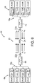
- FIG. 6 shows the replacement of the fiber optical network connections depicted in FIG. 3 using four pairs of bidirectional transceivers Trx#1-Trx#8 (of the type depicted in FIG. 4 ) with an optical cable 62 comprising a gigabit plastic optical fiber 24.
- This network configuration reduces the cables in the airplane by a factor of eight without adversely affecting the operation of the airplane LRU communications. This results in a large reduction in cost and labor for the airplane installation in the factory.
- FIG. 6 is a diagram identifying components of a bidirectional full-duplex data transmission system 60 having one full-duplex optical cable 62 for optically coupling four dual-wavelength single-fiber bidirectional transceivers Trx#1, Trx#3, Trx#5 and Trx#7 of one LRU set 64 of line replaceable units LRU#1, LRU#3, LRU#5 and LRU#7 to four dual-wavelength single-fiber bidirectional transceivers Trx#2, Trx#4, Trx#6 and Trx#8 of another LRU set 66 of line replaceable units LRU#2, LRU#4, LRU#6 and LRU#8.
- the eight dual-wavelength single-fiber bidirectional transceivers Trx#1-Trx#8 transmit light having different wavelengths ⁇ 1 to ⁇ 8 .
- the bidirectional full-duplex data transmission system 60 comprises a first set of four glass optical fibers 18a, a first glass optical fiber coupler 70 connected to the first set of four glass optical fibers 18a, a second set of four glass optical fibers 18b and a second glass optical fiber coupler 68 connected to the second set of four glass optical fibers 18a.
- the four glass optical fibers 18b optically couple the glass optical fiber coupler 70 to the dual-wavelength single-fiber bidirectional transceivers Trx#2, Trx#4, Trx#6 and Trx#8, while the four glass optical fibers 18b optically couple the glass optical fiber coupler 68 to the dual-wavelength single-fiber bidirectional transceivers Trx#1, Trx#3, Trx#5 and Trx#7.
- the bidirectional full-duplex data transmission system 60 further comprises a gigabit plastic optical fiber 24 having one end connected to glass optical fiber coupler 70 by a connector 22a and another end connected to glass optical fiber coupler 68 by a connector 22b.
- the laser 4 of the dual-wavelength single-fiber bidirectional transceiver Trx#1 is optically coupled to emit light having a wavelength ⁇ 1 toward the photodetector 8 of the dual-wavelength single-fiber bidirectional transceiver Trx#2, while the laser 4 of the dual-wavelength single-fiber bidirectional transceiver Trx#2 is optically coupled to emit light having a wavelength ⁇ 2 toward the photodetector 8 of the dual-wavelength single-fiber bidirectional transceiver Trx#1.
- the laser 4 of the dual-wavelength single-fiber bidirectional transceiver Trx#3 is optically coupled to emit light having a wavelength ⁇ 3 toward the photodetector 8 of the dual-wavelength single-fiber bidirectional transceiver Trx#4, while the laser 4 of the dual-wavelength single-fiber bidirectional transceiver Trx#4 is optically coupled to emit light having a wavelength ⁇ 4 toward the photodetector 8 of the dual-wavelength single-fiber bidirectional transceiver Trx#3;
- the laser 4 of the dual-wavelength single-fiber bidirectional transceiver Trx#5 is optically coupled to emit light having a wavelength ⁇ 5 toward the photodetector 8 of the dual-wavelength single-fiber bidirectional transceiver Trx#6, while the laser 4 of the dual-wavelength single-fiber bidirectional transceiver Trx#6 is optically coupled to emit light having a wavelength ⁇ 6 toward the photodetector 8 of the dual-wavelength single-fiber bidirectional transceiver Tr
- Each pair of optically coupled dual-wavelength single-fiber bidirectional transceivers Trx#1 through Trx#8 seen in FIG. 6 comprises a respective WMD optical filter (not shown in FIG. 6 ) of the type depicted in FIG. 4 , except that the WMD optical filters for the respective pairs of transceivers are configured differently for each pair.
- the WMD optical filters inside dual-wavelength single-fiber bidirectional transceivers Trx#1 and Trx#2 are designed to pass light of wavelength ⁇ 1 and reflect light of wavelength ⁇ 2
- the WMD optical filters inside dual-wavelength single-fiber bidirectional transceivers Trx#3 and Trx#4 are designed to pass light of wavelength ⁇ 3 and reflect light of wavelength ⁇ 4 , and so forth.
- the bidirectional full-duplex data transmission system 60 depicted in FIG. 6 is capable of transmitting data at a rate greater than 1 Gbits/sec in either direction due to the presence of gigabit plastic optical fiber 24 in the optical cable 62.
- the wavelengths ⁇ 1 to ⁇ 8 are selected to minimize attenuation in the gigabit plastic optical fiber 24.
- the attenuation of the optical signal as it passes through the optical fiber will vary as a function of the wavelength of the optical signal.
- each optical fiber material has a characteristic function representing the attenuation versus wavelength.
- one plastic optical fiber material that has proven to be suitable for Gigabit Ethernet (GbE) data transmission is perfluorinated polymer having a graded index of refraction and having a high data transmission rate over a wide wavelength range.
- the gigabit plastic optical fiber 24 may be Fontex® plastic optical fiber commercially available from Asahi Glass Co., Ltd., Tokyo, Japan. FIG.
- the attenuation is lowest in the range of 750 nm to 1350 nm.
- Other suitable gigabit plastic optical fiber materials having a range of wavelengths where attenuation is acceptable can be utilized.
- the wavelengths ⁇ 1 through ⁇ 8 are selected from the range of wavelengths where attenuation is relatively low compared to the attenuation at other wavelengths.
- Using these wavelengths provides a low optical loss in the gigabit plastic optical fiber 24 and supports a gigabit plastic optical fiber link of 100 meters or more.
- These wavelength selections also eliminate inter-channel cross-talk between the bidirectional transceivers because there is no overlapping wavelength region in these four pairs of wavelengths.
- the internal WDM filters in the bidirectional transceivers filter out the transmitter signal from the other bidirectional transceiver pairs with different wavelengths.
- the laser 4 in the transmitters of the bidirectional transceivers can be implemented with single-mode distributed feedback lasers, multi-mode Fabry-Perot lasers or vertical cavity surface-emitting lasers for high optical output power and low modal noise.
- the photodetector 8 in the receivers of the bidirectional transceivers can be implemented with a high-responsivity p-type intrinsic n-type (PIN) photodiode or an avalanche photodiode to provide high receiver sensitivity.
- PIN p-type intrinsic n-type
- each of the glass optical fiber couplers 68 and 70 shown in FIG. 6 comprises a 4x1 mode-independent multi-mode optical coupler (formed by heat fusing glass) that optically couples a respective set of four bidirectional transceivers to the opposing ends of the gigabit plastic optical fiber 24.
- the advantages of a mode-independent optical coupler are: (1) it has an optical output splitting ratio independent of the input optical mode from the transmitter's laser source; and (2) the mode-independent optical coupler has optical reflection lower than -40 dB to reduce the optical signal reflected from the adjacent bidirectional transceiver.
- Respective ultra-low-reflection connectors 18a and 18b are used to connect the outputs of the glass optical fiber couplers 68 and 70 to the opposing ends of the gigabit plastic optical fiber 24.
- the end face of the glass optical fiber on one side of the glass optical fiber couplers and the confronting end face of the gigabit plastic optical fiber 24 are angles and polished.
- the ultra-low-reflection connectors 18a and 18b are formed with a small angle at those end faces.
- FIG. 6 does not seek to depict any particular configuration or type of optical fiber connector.
- Each of the connectors 22a and 22b may have a generally circular cylindrical structure.
- some connectors include springs and associated structure for pushing the ends of two fiber optic devices into contact with each other. Such springs and associated structure are also not shown in FIG. 6 .
- the connector's optical coupling loss depends on the quality of the confronting (e.g., abutting) end faces of each glass optical fiber coupler 68 or 70 and gigabit plastic optical fiber 24.
- a poor end face can introduce an additional optical loss per connector.
- the provision of smooth optical fiber end faces is important to reduce the connector's optical coupling loss for avionics networks where the optical cable's power budget is very tight due to relatively long optical cable lengths.
- FIG. 6 comprises a forward set of four line replaceable units optically communicating with an aft set of four line replaceable units on an airplane
- the concepts disclosed herein may be applied in situations where the number of line replaceable units in each of the forward and aft sets is different than four, for example, as few as two and perhaps as many as sixteen if the resulting optical losses are acceptable.
- the system described above may in the alternative be implemented using all glass optical fiber.
- GbPOF is a special application (or solution) where glass fiber is a problem for airplane installation. But for many long-distance terrestrial, data center and fiber-to-the-home/office applications (non-aerospace), glass optical fiber installation is not a major problem.
- the minimum loss region lies in a range of wavelengths from 1350 nm to 1600 nm.
- Example wavelength pairs for glass optical fiber implementation are: 1365 and 1460 nm; 1465 and 1550 nm; 1530 and 1560 nm; 1565 and 1600 nm, and many other possible selections.
- GbGOF and GbPOF have different optical loss characteristics which vary with wavelength as shown in FIGS. 7 and 8 .
- an avionics system may comprise multiple bidirectional transceivers configured to transmit and receive proper wavelengths that correspond to the optical loss minimum for the particular gigabit plastic or glass optical fiber being employed.
- the design disclosed herein enables the use of long gigabit plastic optical fiber links (100 meters or longer) in medium- and large-sized airplanes.
- the configuration disclosed herein reduces the fiber count in the airplane by a factor of eight for the specific example wherein one set of four bidirectional transceivers respectively communicates with four bidirectional transceivers in a corresponding set.
- the fiber count reduction factor will be a function of how many bidirectional transceivers are optically coupled in pairs by a single gigabit plastic or glass optical fiber. The reduced fiber count reduces weight, size and installation cost of fiber cables in the airplane.
- the resulting data transmission system is capable of full-duplex or half-duplex communication between LRUs with a single fiber link.
Landscapes
- Engineering & Computer Science (AREA)
- Computer Networks & Wireless Communication (AREA)
- Signal Processing (AREA)
- Physics & Mathematics (AREA)
- Electromagnetism (AREA)
- Computing Systems (AREA)
- Optics & Photonics (AREA)
- Optical Communication System (AREA)
- Optical Couplings Of Light Guides (AREA)
Applications Claiming Priority (1)
| Application Number | Priority Date | Filing Date | Title |
|---|---|---|---|
| US15/802,523 US10447423B2 (en) | 2017-11-03 | 2017-11-03 | Bidirectional, multi-wavelength gigabit optical fiber network |
Publications (2)
| Publication Number | Publication Date |
|---|---|
| EP3480973A1 true EP3480973A1 (fr) | 2019-05-08 |
| EP3480973B1 EP3480973B1 (fr) | 2020-06-03 |
Family
ID=64051378
Family Applications (1)
| Application Number | Title | Priority Date | Filing Date |
|---|---|---|---|
| EP18202791.2A Active EP3480973B1 (fr) | 2017-11-03 | 2018-10-26 | Réseau de fibre optique gigabit bidirectionnel à longueurs d'ondes multiples |
Country Status (8)
| Country | Link |
|---|---|
| US (1) | US10447423B2 (fr) |
| EP (1) | EP3480973B1 (fr) |
| JP (1) | JP7294787B2 (fr) |
| KR (1) | KR102531047B1 (fr) |
| CN (1) | CN109861755B (fr) |
| BR (1) | BR102018071841A8 (fr) |
| CA (1) | CA3021438C (fr) |
| TW (1) | TWI784066B (fr) |
Cited By (1)
| Publication number | Priority date | Publication date | Assignee | Title |
|---|---|---|---|---|
| CN111431610A (zh) * | 2020-02-21 | 2020-07-17 | 北京仿真中心 | 串行通信中继装置及系统 |
Families Citing this family (13)
| Publication number | Priority date | Publication date | Assignee | Title |
|---|---|---|---|---|
| CN110635847B (zh) * | 2018-06-21 | 2021-08-03 | 华为技术有限公司 | 一种光网络装置和光模块 |
| US11664902B2 (en) | 2019-08-19 | 2023-05-30 | Nokia Solutions And Networks Oy | Planar assemblies for optical transceivers |
| US10998976B2 (en) * | 2019-08-26 | 2021-05-04 | The Boeing Company | Process for extending operating temperature range of gigabit plastic optical fiber |
| US11491651B2 (en) | 2020-03-03 | 2022-11-08 | The Boeing Company | Data communication network with gigabit plastic optical fiber for robotic arm system |
| US11630274B2 (en) | 2020-04-01 | 2023-04-18 | Mellanox Technologies, Ltd. | High-density optical communications using multi-core fiber |
| US11561352B2 (en) | 2020-04-01 | 2023-01-24 | Mellanox Technologies, Ltd. | High density optical I/O inside a data center switch using multi-core fibers |
| US11378765B2 (en) | 2020-05-25 | 2022-07-05 | Mellanox Technologies, Ltd. | Intra data center and inter data center links using dual-wavelength multimode/singlemode multi-core fiber |
| US11303379B1 (en) * | 2020-11-05 | 2022-04-12 | Mellanox Technologies, Ltd. | Communication between data centers using a multi-core fiber |
| CN112994830B (zh) * | 2021-02-08 | 2023-01-03 | 中车青岛四方机车车辆股份有限公司 | 一种基于光纤波分复用的车载网络系统及传输方法 |
| US11683099B1 (en) | 2021-09-24 | 2023-06-20 | Cisco Technology, Inc. | Gigabit multimode bidirectional optical module |
| CN113890612A (zh) * | 2021-09-28 | 2022-01-04 | 武汉恒泰通技术有限公司 | 一种基于wdm波分的光纤滤波系统 |
| US12068843B1 (en) | 2022-09-28 | 2024-08-20 | Rockwell Collins, Inc. | Wavelength division multiplexing (WDM) approach to phase lock distributed digital and RF electronics over fiber |
| CN119846786A (zh) * | 2023-10-17 | 2025-04-18 | 华为技术有限公司 | 光通信组件、光通信设备和光通信系统 |
Citations (3)
| Publication number | Priority date | Publication date | Assignee | Title |
|---|---|---|---|---|
| WO2009035202A1 (fr) * | 2007-09-10 | 2009-03-19 | Electronics And Telecommunications Research Institute | Système de réseau optique passif multiple |
| EP2091166A1 (fr) * | 2008-02-13 | 2009-08-19 | Oki Electric Industry Co., Ltd. | Système de communication de réseau optique passif |
| US20140270778A1 (en) * | 2013-03-12 | 2014-09-18 | Avago Technologies General Ip (Singapore) Pte. Ltd. | Bidirectional optical data communications module |
Family Cites Families (49)
| Publication number | Priority date | Publication date | Assignee | Title |
|---|---|---|---|---|
| DE2625855A1 (de) * | 1976-06-09 | 1977-12-22 | Siemens Ag | Ein-/auskoppler fuer multimode-lichtleitfasern |
| US4997247A (en) * | 1987-09-17 | 1991-03-05 | Aster Corporation | Fiber optic coupler and method for making same |
| US5109447A (en) * | 1991-03-04 | 1992-04-28 | The Boeing Company | High-powered, spectrally flat, very broadband optical source including optical coupler and method using same |
| US5222166A (en) * | 1992-05-19 | 1993-06-22 | Rockwell International Corporation | Aircraft fiber optic data distribution system |
| US5963349A (en) * | 1997-01-27 | 1999-10-05 | Lucent Technologies Inc. | Inexpensive single-fiber bidirectional data link |
| DE19746350A1 (de) * | 1997-10-21 | 1999-04-22 | Bosch Gmbh Robert | Transceiver für Wellenlängemultiplex-Verfahren |
| JP2002202442A (ja) * | 2000-11-06 | 2002-07-19 | Fuji Photo Film Co Ltd | 合波レーザー光源および露光装置 |
| US6944404B2 (en) * | 2000-12-11 | 2005-09-13 | Harris Corporation | Network transceiver for extending the bandwidth of optical fiber-based network infrastructure |
| GB0124234D0 (en) * | 2001-10-09 | 2001-11-28 | Marconi Comm Ltd | Apparatus for data transmission |
| CN1428959A (zh) * | 2001-12-26 | 2003-07-09 | 上海贝尔有限公司 | 一种双向波分复用光网络系统 |
| US7171081B1 (en) * | 2002-03-14 | 2007-01-30 | Lightech Fiberoptics, Inc. | Plug-in coupler to convert the transceiver (transmitter/receiver, tx/rx) transmission into a bi-directional fiber |
| US6665322B2 (en) * | 2002-03-19 | 2003-12-16 | San Jose Systems Inc. | Method and apparatus for controlling the length of an optical cavity |
| US6951426B2 (en) * | 2003-03-05 | 2005-10-04 | Finisar Corporation | Pad architecture for backwards compatibility for bi-directional transceiver module |
| NL1024015C2 (nl) * | 2003-07-28 | 2005-02-01 | Draka Fibre Technology Bv | Multimode optische vezel voorzien van een brekingsindexprofiel, optisch communicatiesysteem onder toepassing daarvan en werkwijze ter vervaardiging van een dergelijke vezel. |
| KR100575983B1 (ko) * | 2003-08-23 | 2006-05-02 | 삼성전자주식회사 | 다파장 광송신기와 이를 이용한 양방향 파장 분할 다중시스템 |
| KR20050024644A (ko) * | 2003-09-01 | 2005-03-11 | 삼성전자주식회사 | 양방향 파장분할다중방식 수동형 광 가입자망 및 이의파장대역 할당방법 |
| US20050089332A1 (en) * | 2003-10-03 | 2005-04-28 | Near Margalit | Long reach optical transmission over a single fiber |
| US7158700B2 (en) * | 2004-05-14 | 2007-01-02 | Moog Inc. | Fiber-optic transceiver |
| US8000607B2 (en) * | 2005-01-25 | 2011-08-16 | Finisar Corporation | Optical transceivers with closed-loop digital diagnostics |
| JP4852260B2 (ja) * | 2005-05-16 | 2012-01-11 | 三菱電機株式会社 | 1心双方向波長多重伝送システム |
| KR100711352B1 (ko) * | 2005-06-23 | 2007-04-27 | 삼성전자주식회사 | 파장 잠김된 광송신기를 이용한 파장분할다중 방식의수동형 광네트워크 |
| US7840138B2 (en) * | 2005-11-01 | 2010-11-23 | Technology Advancement Group, Inc. | Method and system for bi-directional communication over a single optical fiber |
| DE602007009658D1 (de) * | 2006-03-17 | 2010-11-18 | Nkt Photonics As | Optischer koppler und verfahren zu seiner herstellung und verwendung |
| US7359592B2 (en) | 2006-03-21 | 2008-04-15 | The Boeing Company | Single fiber links for full duplex aircraft data network |
| JP2009128371A (ja) * | 2007-11-19 | 2009-06-11 | Fujikura Ltd | マルチモード光カプラ |
| US7903706B2 (en) * | 2008-04-04 | 2011-03-08 | O'shaughnessy John | Compact, thermally stable multi-laser engine |
| US7965913B2 (en) | 2008-04-11 | 2011-06-21 | The Boeing Company | Optical star coupler |
| US8306421B1 (en) * | 2008-05-05 | 2012-11-06 | Rockwell Collins, Inc. | Passive optical avionics network including optical repeater |
| US8532489B2 (en) * | 2009-03-04 | 2013-09-10 | Futurewei Technologies, Inc. | Multi-fiber ten gigabit passive optical network optical line terminal for optical distribution network coexistence with gigabit passive optical network |
| US8285144B2 (en) * | 2009-07-30 | 2012-10-09 | Jds Uniphase Corporation | Optical device for rearranging wavelength channels |
| US8903247B2 (en) * | 2009-10-30 | 2014-12-02 | Cisco Technology, Inc. | Bidirectional multi-mode fiber interface |
| US8725001B2 (en) * | 2010-03-10 | 2014-05-13 | Ofs Fitel, Llc | Multicore fiber transmission systems and methods |
| US8521032B2 (en) * | 2010-04-01 | 2013-08-27 | The Boeing Company | Optical fiber interface system and connector |
| JP2012049844A (ja) * | 2010-08-27 | 2012-03-08 | Panasonic Corp | 光データ伝送システム |
| US9031419B2 (en) * | 2011-09-28 | 2015-05-12 | At&T Intellectual Property I, L.P. | Optical networks using multi-spatial mode media |
| US8891964B2 (en) * | 2011-12-12 | 2014-11-18 | Nec Laboratories America, Inc. | Dynamic multidimensional optical networking based on spatial and spectral processing |
| US8554032B2 (en) | 2011-12-12 | 2013-10-08 | The Boeing Company | Optical star coupler for plastic optical fibers |
| US9112600B2 (en) * | 2012-04-20 | 2015-08-18 | Electronics And Telecommunications Research Institute | Wavelength tuning time measurement apparatus and method for multi-wavelength passive optical network |
| JP6077263B2 (ja) * | 2012-10-16 | 2017-02-08 | 古河電気工業株式会社 | レーザ装置 |
| US9209901B2 (en) * | 2012-11-20 | 2015-12-08 | Telefonaktiebolaget L M Ericsson (Publ) | Configurable single-fiber or dual-fiber optical transceiver |
| US10564357B2 (en) * | 2013-07-30 | 2020-02-18 | The Boeing Company | Plastic optical fiber bus network using tapered mixing rods |
| US11300730B2 (en) * | 2013-07-30 | 2022-04-12 | The Boeing Company | Plastic and glass optical fiber bus network having plural line replaceable units transmitting to a mixing rod |
| US20160085027A1 (en) | 2013-07-30 | 2016-03-24 | The Boeing Company | Tapered optical mixing rods |
| US9791644B2 (en) | 2014-11-05 | 2017-10-17 | The Boeing Company | Data bus-in-a-box (BiB) system design and implementation |
| CN107005305B (zh) * | 2014-12-01 | 2020-08-21 | 德拉克通信科技公司 | 用于表征和制造多模光纤链路的方法及改进其性能的方法 |
| US9729267B2 (en) * | 2014-12-11 | 2017-08-08 | Corning Optical Communications Wireless Ltd | Multiplexing two separate optical links with the same wavelength using asymmetric combining and splitting |
| US10284288B2 (en) * | 2016-02-18 | 2019-05-07 | Apriori Network Systems, Llc | Secured fiber link system |
| US10291346B2 (en) * | 2016-03-22 | 2019-05-14 | Finisar Corporation | Bidirectional communication module |
| JP6690347B2 (ja) * | 2016-03-25 | 2020-04-28 | 富士通株式会社 | 光通信システム、送信局及び光通信方法 |
-
2017
- 2017-11-03 US US15/802,523 patent/US10447423B2/en active Active
-
2018
- 2018-10-08 TW TW107135413A patent/TWI784066B/zh active
- 2018-10-11 JP JP2018192473A patent/JP7294787B2/ja active Active
- 2018-10-19 CA CA3021438A patent/CA3021438C/fr active Active
- 2018-10-24 BR BR102018071841A patent/BR102018071841A8/pt unknown
- 2018-10-26 EP EP18202791.2A patent/EP3480973B1/fr active Active
- 2018-10-30 CN CN201811274573.8A patent/CN109861755B/zh active Active
- 2018-11-02 KR KR1020180133573A patent/KR102531047B1/ko active Active
Patent Citations (3)
| Publication number | Priority date | Publication date | Assignee | Title |
|---|---|---|---|---|
| WO2009035202A1 (fr) * | 2007-09-10 | 2009-03-19 | Electronics And Telecommunications Research Institute | Système de réseau optique passif multiple |
| EP2091166A1 (fr) * | 2008-02-13 | 2009-08-19 | Oki Electric Industry Co., Ltd. | Système de communication de réseau optique passif |
| US20140270778A1 (en) * | 2013-03-12 | 2014-09-18 | Avago Technologies General Ip (Singapore) Pte. Ltd. | Bidirectional optical data communications module |
Cited By (1)
| Publication number | Priority date | Publication date | Assignee | Title |
|---|---|---|---|---|
| CN111431610A (zh) * | 2020-02-21 | 2020-07-17 | 北京仿真中心 | 串行通信中继装置及系统 |
Also Published As
| Publication number | Publication date |
|---|---|
| US20190140761A1 (en) | 2019-05-09 |
| CA3021438A1 (fr) | 2019-05-03 |
| EP3480973B1 (fr) | 2020-06-03 |
| US10447423B2 (en) | 2019-10-15 |
| CN109861755A (zh) | 2019-06-07 |
| JP7294787B2 (ja) | 2023-06-20 |
| CN109861755B (zh) | 2023-04-07 |
| TWI784066B (zh) | 2022-11-21 |
| CA3021438C (fr) | 2022-12-06 |
| BR102018071841A8 (pt) | 2023-02-14 |
| KR20190050715A (ko) | 2019-05-13 |
| JP2019087995A (ja) | 2019-06-06 |
| KR102531047B1 (ko) | 2023-05-09 |
| BR102018071841A2 (pt) | 2019-06-04 |
| TW201924247A (zh) | 2019-06-16 |
Similar Documents
| Publication | Publication Date | Title |
|---|---|---|
| CA3021438C (fr) | Reseau de fibres optiques gigaoctet multi longueurs d'onde, bidirectionnel | |
| CN101621349B (zh) | 利用多模光纤的波长多路复用光学系统 | |
| US9692515B2 (en) | Multimode optical transmission system and method employing HOM-filter fiber | |
| KR102592524B1 (ko) | 통합된 광섬유 커플러를 가진 단일-파장 양방향 트랜시버 | |
| Hayashi et al. | 125-µm-cladding 8-core multi-core fiber realizing ultra-high-density cable suitable for O-band short-reach optical interconnects | |
| WO2006083938A2 (fr) | Bout de fibre pour reduction de couplage en mode de gaine | |
| CN108572419B (zh) | 长距离有源光缆 | |
| US20180269973A1 (en) | Multimode fiber for modulatable source | |
| Zhu | SDM fibers for data center applications | |
| US8903247B2 (en) | Bidirectional multi-mode fiber interface | |
| US20040161240A1 (en) | Module having two bi-directional optical transceivers | |
| Zakharian et al. | Impact of multi-path interference on single mode transmission over multi-mode fibers | |
| WO2019213163A1 (fr) | Dispositif de conditionnement de mode optique mmf | |
| Xiao et al. | Wideband Small Core Diameter Graded-index Fiber and its Compatibility with Multimode Transceiver and Single-mode Transceiver in Transmission System | |
| EP3847489A1 (fr) | Coupleur de smf à mmf | |
| Geckeler | FIBRE-OPTICAL COMMUNICATION IN COMPUTER SYSTEMS |
Legal Events
| Date | Code | Title | Description |
|---|---|---|---|
| PUAI | Public reference made under article 153(3) epc to a published international application that has entered the european phase |
Free format text: ORIGINAL CODE: 0009012 |
|
| STAA | Information on the status of an ep patent application or granted ep patent |
Free format text: STATUS: REQUEST FOR EXAMINATION WAS MADE |
|
| 17P | Request for examination filed |
Effective date: 20181026 |
|
| AK | Designated contracting states |
Kind code of ref document: A1 Designated state(s): AL AT BE BG CH CY CZ DE DK EE ES FI FR GB GR HR HU IE IS IT LI LT LU LV MC MK MT NL NO PL PT RO RS SE SI SK SM TR |
|
| AX | Request for extension of the european patent |
Extension state: BA ME |
|
| REG | Reference to a national code |
Ref country code: DE Ref legal event code: R079 Ref document number: 602018005059 Country of ref document: DE Free format text: PREVIOUS MAIN CLASS: H04B0010250000 Ipc: H04B0010400000 |
|
| GRAJ | Information related to disapproval of communication of intention to grant by the applicant or resumption of examination proceedings by the epo deleted |
Free format text: ORIGINAL CODE: EPIDOSDIGR1 |
|
| STAA | Information on the status of an ep patent application or granted ep patent |
Free format text: STATUS: GRANT OF PATENT IS INTENDED |
|
| GRAP | Despatch of communication of intention to grant a patent |
Free format text: ORIGINAL CODE: EPIDOSNIGR1 |
|
| RIC1 | Information provided on ipc code assigned before grant |
Ipc: H04J 14/02 20060101ALI20191203BHEP Ipc: H04B 10/278 20130101ALI20191203BHEP Ipc: H04B 10/25 20130101ALI20191203BHEP Ipc: H04B 10/40 20130101AFI20191203BHEP Ipc: G02B 6/12 20060101ALI20191203BHEP |
|
| INTG | Intention to grant announced |
Effective date: 20200108 |
|
| GRAJ | Information related to disapproval of communication of intention to grant by the applicant or resumption of examination proceedings by the epo deleted |
Free format text: ORIGINAL CODE: EPIDOSDIGR1 |
|
| STAA | Information on the status of an ep patent application or granted ep patent |
Free format text: STATUS: REQUEST FOR EXAMINATION WAS MADE |
|
| GRAJ | Information related to disapproval of communication of intention to grant by the applicant or resumption of examination proceedings by the epo deleted |
Free format text: ORIGINAL CODE: EPIDOSDIGR1 |
|
| GRAP | Despatch of communication of intention to grant a patent |
Free format text: ORIGINAL CODE: EPIDOSNIGR1 |
|
| GRAR | Information related to intention to grant a patent recorded |
Free format text: ORIGINAL CODE: EPIDOSNIGR71 |
|
| GRAS | Grant fee paid |
Free format text: ORIGINAL CODE: EPIDOSNIGR3 |
|
| STAA | Information on the status of an ep patent application or granted ep patent |
Free format text: STATUS: GRANT OF PATENT IS INTENDED |
|
| GRAA | (expected) grant |
Free format text: ORIGINAL CODE: 0009210 |
|
| STAA | Information on the status of an ep patent application or granted ep patent |
Free format text: STATUS: THE PATENT HAS BEEN GRANTED |
|
| INTC | Intention to grant announced (deleted) | ||
| AK | Designated contracting states |
Kind code of ref document: B1 Designated state(s): AL AT BE BG CH CY CZ DE DK EE ES FI FR GB GR HR HU IE IS IT LI LT LU LV MC MK MT NL NO PL PT RO RS SE SI SK SM TR |
|
| INTG | Intention to grant announced |
Effective date: 20200427 |
|
| REG | Reference to a national code |
Ref country code: GB Ref legal event code: FG4D |
|
| REG | Reference to a national code |
Ref country code: CH Ref legal event code: EP Ref country code: AT Ref legal event code: REF Ref document number: 1278129 Country of ref document: AT Kind code of ref document: T Effective date: 20200615 |
|
| REG | Reference to a national code |
Ref country code: DE Ref legal event code: R096 Ref document number: 602018005059 Country of ref document: DE |
|
| REG | Reference to a national code |
Ref country code: LT Ref legal event code: MG4D |
|
| PG25 | Lapsed in a contracting state [announced via postgrant information from national office to epo] |
Ref country code: GR Free format text: LAPSE BECAUSE OF FAILURE TO SUBMIT A TRANSLATION OF THE DESCRIPTION OR TO PAY THE FEE WITHIN THE PRESCRIBED TIME-LIMIT Effective date: 20200904 Ref country code: FI Free format text: LAPSE BECAUSE OF FAILURE TO SUBMIT A TRANSLATION OF THE DESCRIPTION OR TO PAY THE FEE WITHIN THE PRESCRIBED TIME-LIMIT Effective date: 20200603 Ref country code: NO Free format text: LAPSE BECAUSE OF FAILURE TO SUBMIT A TRANSLATION OF THE DESCRIPTION OR TO PAY THE FEE WITHIN THE PRESCRIBED TIME-LIMIT Effective date: 20200903 Ref country code: SE Free format text: LAPSE BECAUSE OF FAILURE TO SUBMIT A TRANSLATION OF THE DESCRIPTION OR TO PAY THE FEE WITHIN THE PRESCRIBED TIME-LIMIT Effective date: 20200603 Ref country code: LT Free format text: LAPSE BECAUSE OF FAILURE TO SUBMIT A TRANSLATION OF THE DESCRIPTION OR TO PAY THE FEE WITHIN THE PRESCRIBED TIME-LIMIT Effective date: 20200603 |
|
| REG | Reference to a national code |
Ref country code: NL Ref legal event code: MP Effective date: 20200603 |
|
| PG25 | Lapsed in a contracting state [announced via postgrant information from national office to epo] |
Ref country code: RS Free format text: LAPSE BECAUSE OF FAILURE TO SUBMIT A TRANSLATION OF THE DESCRIPTION OR TO PAY THE FEE WITHIN THE PRESCRIBED TIME-LIMIT Effective date: 20200603 Ref country code: BG Free format text: LAPSE BECAUSE OF FAILURE TO SUBMIT A TRANSLATION OF THE DESCRIPTION OR TO PAY THE FEE WITHIN THE PRESCRIBED TIME-LIMIT Effective date: 20200903 Ref country code: LV Free format text: LAPSE BECAUSE OF FAILURE TO SUBMIT A TRANSLATION OF THE DESCRIPTION OR TO PAY THE FEE WITHIN THE PRESCRIBED TIME-LIMIT Effective date: 20200603 Ref country code: HR Free format text: LAPSE BECAUSE OF FAILURE TO SUBMIT A TRANSLATION OF THE DESCRIPTION OR TO PAY THE FEE WITHIN THE PRESCRIBED TIME-LIMIT Effective date: 20200603 |
|
| REG | Reference to a national code |
Ref country code: AT Ref legal event code: MK05 Ref document number: 1278129 Country of ref document: AT Kind code of ref document: T Effective date: 20200603 |
|
| PG25 | Lapsed in a contracting state [announced via postgrant information from national office to epo] |
Ref country code: NL Free format text: LAPSE BECAUSE OF FAILURE TO SUBMIT A TRANSLATION OF THE DESCRIPTION OR TO PAY THE FEE WITHIN THE PRESCRIBED TIME-LIMIT Effective date: 20200603 Ref country code: AL Free format text: LAPSE BECAUSE OF FAILURE TO SUBMIT A TRANSLATION OF THE DESCRIPTION OR TO PAY THE FEE WITHIN THE PRESCRIBED TIME-LIMIT Effective date: 20200603 |
|
| PG25 | Lapsed in a contracting state [announced via postgrant information from national office to epo] |
Ref country code: ES Free format text: LAPSE BECAUSE OF FAILURE TO SUBMIT A TRANSLATION OF THE DESCRIPTION OR TO PAY THE FEE WITHIN THE PRESCRIBED TIME-LIMIT Effective date: 20200603 Ref country code: EE Free format text: LAPSE BECAUSE OF FAILURE TO SUBMIT A TRANSLATION OF THE DESCRIPTION OR TO PAY THE FEE WITHIN THE PRESCRIBED TIME-LIMIT Effective date: 20200603 Ref country code: AT Free format text: LAPSE BECAUSE OF FAILURE TO SUBMIT A TRANSLATION OF THE DESCRIPTION OR TO PAY THE FEE WITHIN THE PRESCRIBED TIME-LIMIT Effective date: 20200603 Ref country code: IT Free format text: LAPSE BECAUSE OF FAILURE TO SUBMIT A TRANSLATION OF THE DESCRIPTION OR TO PAY THE FEE WITHIN THE PRESCRIBED TIME-LIMIT Effective date: 20200603 Ref country code: SM Free format text: LAPSE BECAUSE OF FAILURE TO SUBMIT A TRANSLATION OF THE DESCRIPTION OR TO PAY THE FEE WITHIN THE PRESCRIBED TIME-LIMIT Effective date: 20200603 Ref country code: CZ Free format text: LAPSE BECAUSE OF FAILURE TO SUBMIT A TRANSLATION OF THE DESCRIPTION OR TO PAY THE FEE WITHIN THE PRESCRIBED TIME-LIMIT Effective date: 20200603 Ref country code: PT Free format text: LAPSE BECAUSE OF FAILURE TO SUBMIT A TRANSLATION OF THE DESCRIPTION OR TO PAY THE FEE WITHIN THE PRESCRIBED TIME-LIMIT Effective date: 20201006 Ref country code: RO Free format text: LAPSE BECAUSE OF FAILURE TO SUBMIT A TRANSLATION OF THE DESCRIPTION OR TO PAY THE FEE WITHIN THE PRESCRIBED TIME-LIMIT Effective date: 20200603 |
|
| PG25 | Lapsed in a contracting state [announced via postgrant information from national office to epo] |
Ref country code: PL Free format text: LAPSE BECAUSE OF FAILURE TO SUBMIT A TRANSLATION OF THE DESCRIPTION OR TO PAY THE FEE WITHIN THE PRESCRIBED TIME-LIMIT Effective date: 20200603 Ref country code: SK Free format text: LAPSE BECAUSE OF FAILURE TO SUBMIT A TRANSLATION OF THE DESCRIPTION OR TO PAY THE FEE WITHIN THE PRESCRIBED TIME-LIMIT Effective date: 20200603 Ref country code: IS Free format text: LAPSE BECAUSE OF FAILURE TO SUBMIT A TRANSLATION OF THE DESCRIPTION OR TO PAY THE FEE WITHIN THE PRESCRIBED TIME-LIMIT Effective date: 20201003 |
|
| REG | Reference to a national code |
Ref country code: DE Ref legal event code: R097 Ref document number: 602018005059 Country of ref document: DE |
|
| PLBE | No opposition filed within time limit |
Free format text: ORIGINAL CODE: 0009261 |
|
| STAA | Information on the status of an ep patent application or granted ep patent |
Free format text: STATUS: NO OPPOSITION FILED WITHIN TIME LIMIT |
|
| PG25 | Lapsed in a contracting state [announced via postgrant information from national office to epo] |
Ref country code: DK Free format text: LAPSE BECAUSE OF FAILURE TO SUBMIT A TRANSLATION OF THE DESCRIPTION OR TO PAY THE FEE WITHIN THE PRESCRIBED TIME-LIMIT Effective date: 20200603 |
|
| 26N | No opposition filed |
Effective date: 20210304 |
|
| PG25 | Lapsed in a contracting state [announced via postgrant information from national office to epo] |
Ref country code: SI Free format text: LAPSE BECAUSE OF FAILURE TO SUBMIT A TRANSLATION OF THE DESCRIPTION OR TO PAY THE FEE WITHIN THE PRESCRIBED TIME-LIMIT Effective date: 20200603 |
|
| PG25 | Lapsed in a contracting state [announced via postgrant information from national office to epo] |
Ref country code: MC Free format text: LAPSE BECAUSE OF FAILURE TO SUBMIT A TRANSLATION OF THE DESCRIPTION OR TO PAY THE FEE WITHIN THE PRESCRIBED TIME-LIMIT Effective date: 20200603 Ref country code: LU Free format text: LAPSE BECAUSE OF NON-PAYMENT OF DUE FEES Effective date: 20201026 |
|
| REG | Reference to a national code |
Ref country code: BE Ref legal event code: MM Effective date: 20201031 |
|
| PG25 | Lapsed in a contracting state [announced via postgrant information from national office to epo] |
Ref country code: BE Free format text: LAPSE BECAUSE OF NON-PAYMENT OF DUE FEES Effective date: 20201031 |
|
| PG25 | Lapsed in a contracting state [announced via postgrant information from national office to epo] |
Ref country code: IE Free format text: LAPSE BECAUSE OF NON-PAYMENT OF DUE FEES Effective date: 20201026 |
|
| REG | Reference to a national code |
Ref country code: CH Ref legal event code: PL |
|
| PG25 | Lapsed in a contracting state [announced via postgrant information from national office to epo] |
Ref country code: TR Free format text: LAPSE BECAUSE OF FAILURE TO SUBMIT A TRANSLATION OF THE DESCRIPTION OR TO PAY THE FEE WITHIN THE PRESCRIBED TIME-LIMIT Effective date: 20200603 Ref country code: MT Free format text: LAPSE BECAUSE OF FAILURE TO SUBMIT A TRANSLATION OF THE DESCRIPTION OR TO PAY THE FEE WITHIN THE PRESCRIBED TIME-LIMIT Effective date: 20200603 Ref country code: CY Free format text: LAPSE BECAUSE OF FAILURE TO SUBMIT A TRANSLATION OF THE DESCRIPTION OR TO PAY THE FEE WITHIN THE PRESCRIBED TIME-LIMIT Effective date: 20200603 |
|
| PG25 | Lapsed in a contracting state [announced via postgrant information from national office to epo] |
Ref country code: MK Free format text: LAPSE BECAUSE OF FAILURE TO SUBMIT A TRANSLATION OF THE DESCRIPTION OR TO PAY THE FEE WITHIN THE PRESCRIBED TIME-LIMIT Effective date: 20200603 |
|
| PG25 | Lapsed in a contracting state [announced via postgrant information from national office to epo] |
Ref country code: LI Free format text: LAPSE BECAUSE OF NON-PAYMENT OF DUE FEES Effective date: 20211031 Ref country code: CH Free format text: LAPSE BECAUSE OF NON-PAYMENT OF DUE FEES Effective date: 20211031 |
|
| P01 | Opt-out of the competence of the unified patent court (upc) registered |
Effective date: 20230516 |
|
| PGFP | Annual fee paid to national office [announced via postgrant information from national office to epo] |
Ref country code: DE Payment date: 20251029 Year of fee payment: 8 |
|
| PGFP | Annual fee paid to national office [announced via postgrant information from national office to epo] |
Ref country code: GB Payment date: 20251027 Year of fee payment: 8 |
|
| PGFP | Annual fee paid to national office [announced via postgrant information from national office to epo] |
Ref country code: FR Payment date: 20251027 Year of fee payment: 8 |