EP3481004B1 - Système de communication, dispositif de communication utilisé dans celui-ci, dispositif de gestion, et terminal d'information - Google Patents
Système de communication, dispositif de communication utilisé dans celui-ci, dispositif de gestion, et terminal d'information Download PDFInfo
- Publication number
- EP3481004B1 EP3481004B1 EP17820273.5A EP17820273A EP3481004B1 EP 3481004 B1 EP3481004 B1 EP 3481004B1 EP 17820273 A EP17820273 A EP 17820273A EP 3481004 B1 EP3481004 B1 EP 3481004B1
- Authority
- EP
- European Patent Office
- Prior art keywords
- communications
- information
- user
- authentication
- communications device
- Prior art date
- Legal status (The legal status is an assumption and is not a legal conclusion. Google has not performed a legal analysis and makes no representation as to the accuracy of the status listed.)
- Active
Links
Images






Classifications
-
- G—PHYSICS
- G06—COMPUTING OR CALCULATING; COUNTING
- G06F—ELECTRIC DIGITAL DATA PROCESSING
- G06F21/00—Security arrangements for protecting computers, components thereof, programs or data against unauthorised activity
- G06F21/30—Authentication, i.e. establishing the identity or authorisation of security principals
- G06F21/31—User authentication
-
- H—ELECTRICITY
- H04—ELECTRIC COMMUNICATION TECHNIQUE
- H04L—TRANSMISSION OF DIGITAL INFORMATION, e.g. TELEGRAPHIC COMMUNICATION
- H04L63/00—Network architectures or network communication protocols for network security
- H04L63/08—Network architectures or network communication protocols for network security for authentication of entities
- H04L63/083—Network architectures or network communication protocols for network security for authentication of entities using passwords
-
- H—ELECTRICITY
- H04—ELECTRIC COMMUNICATION TECHNIQUE
- H04L—TRANSMISSION OF DIGITAL INFORMATION, e.g. TELEGRAPHIC COMMUNICATION
- H04L63/00—Network architectures or network communication protocols for network security
- H04L63/04—Network architectures or network communication protocols for network security for providing a confidential data exchange among entities communicating through data packet networks
- H04L63/0428—Network architectures or network communication protocols for network security for providing a confidential data exchange among entities communicating through data packet networks wherein the data content is protected, e.g. by encrypting or encapsulating the payload
-
- G—PHYSICS
- G06—COMPUTING OR CALCULATING; COUNTING
- G06F—ELECTRIC DIGITAL DATA PROCESSING
- G06F21/00—Security arrangements for protecting computers, components thereof, programs or data against unauthorised activity
- G06F21/30—Authentication, i.e. establishing the identity or authorisation of security principals
- G06F21/44—Program or device authentication
-
- H—ELECTRICITY
- H04—ELECTRIC COMMUNICATION TECHNIQUE
- H04L—TRANSMISSION OF DIGITAL INFORMATION, e.g. TELEGRAPHIC COMMUNICATION
- H04L63/00—Network architectures or network communication protocols for network security
- H04L63/08—Network architectures or network communication protocols for network security for authentication of entities
- H04L63/0876—Network architectures or network communication protocols for network security for authentication of entities based on the identity of the terminal or configuration, e.g. MAC address, hardware or software configuration or device fingerprint
-
- H—ELECTRICITY
- H04—ELECTRIC COMMUNICATION TECHNIQUE
- H04L—TRANSMISSION OF DIGITAL INFORMATION, e.g. TELEGRAPHIC COMMUNICATION
- H04L63/00—Network architectures or network communication protocols for network security
- H04L63/08—Network architectures or network communication protocols for network security for authentication of entities
- H04L63/0884—Network architectures or network communication protocols for network security for authentication of entities by delegation of authentication, e.g. a proxy authenticates an entity to be authenticated on behalf of this entity vis-à-vis an authentication entity
-
- H—ELECTRICITY
- H04—ELECTRIC COMMUNICATION TECHNIQUE
- H04L—TRANSMISSION OF DIGITAL INFORMATION, e.g. TELEGRAPHIC COMMUNICATION
- H04L63/00—Network architectures or network communication protocols for network security
- H04L63/10—Network architectures or network communication protocols for network security for controlling access to devices or network resources
- H04L63/101—Access control lists [ACL]
-
- H—ELECTRICITY
- H04—ELECTRIC COMMUNICATION TECHNIQUE
- H04L—TRANSMISSION OF DIGITAL INFORMATION, e.g. TELEGRAPHIC COMMUNICATION
- H04L63/00—Network architectures or network communication protocols for network security
- H04L63/10—Network architectures or network communication protocols for network security for controlling access to devices or network resources
- H04L63/104—Grouping of entities
-
- H—ELECTRICITY
- H04—ELECTRIC COMMUNICATION TECHNIQUE
- H04L—TRANSMISSION OF DIGITAL INFORMATION, e.g. TELEGRAPHIC COMMUNICATION
- H04L9/00—Cryptographic mechanisms or cryptographic arrangements for secret or secure communications; Network security protocols
- H04L9/10—Cryptographic mechanisms or cryptographic arrangements for secret or secure communications; Network security protocols with particular housing, physical features or manual controls
-
- H—ELECTRICITY
- H04—ELECTRIC COMMUNICATION TECHNIQUE
- H04L—TRANSMISSION OF DIGITAL INFORMATION, e.g. TELEGRAPHIC COMMUNICATION
- H04L9/00—Cryptographic mechanisms or cryptographic arrangements for secret or secure communications; Network security protocols
- H04L9/32—Cryptographic mechanisms or cryptographic arrangements for secret or secure communications; Network security protocols including means for verifying the identity or authority of a user of the system or for message authentication, e.g. authorization, entity authentication, data integrity or data verification, non-repudiation, key authentication or verification of credentials
-
- H—ELECTRICITY
- H04—ELECTRIC COMMUNICATION TECHNIQUE
- H04W—WIRELESS COMMUNICATION NETWORKS
- H04W12/00—Security arrangements; Authentication; Protecting privacy or anonymity
- H04W12/03—Protecting confidentiality, e.g. by encryption
- H04W12/033—Protecting confidentiality, e.g. by encryption of the user plane, e.g. user's traffic
-
- H—ELECTRICITY
- H04—ELECTRIC COMMUNICATION TECHNIQUE
- H04W—WIRELESS COMMUNICATION NETWORKS
- H04W12/00—Security arrangements; Authentication; Protecting privacy or anonymity
- H04W12/06—Authentication
-
- G—PHYSICS
- G06—COMPUTING OR CALCULATING; COUNTING
- G06F—ELECTRIC DIGITAL DATA PROCESSING
- G06F2221/00—Indexing scheme relating to security arrangements for protecting computers, components thereof, programs or data against unauthorised activity
- G06F2221/21—Indexing scheme relating to G06F21/00 and subgroups addressing additional information or applications relating to security arrangements for protecting computers, components thereof, programs or data against unauthorised activity
- G06F2221/2115—Third party
-
- H—ELECTRICITY
- H04—ELECTRIC COMMUNICATION TECHNIQUE
- H04L—TRANSMISSION OF DIGITAL INFORMATION, e.g. TELEGRAPHIC COMMUNICATION
- H04L2463/00—Additional details relating to network architectures or network communication protocols for network security covered by H04L63/00
- H04L2463/082—Additional details relating to network architectures or network communication protocols for network security covered by H04L63/00 applying multi-factor authentication
Definitions
- the present invention relates to a communications system enabling exchange of data between an information terminal and another information terminal via a global network.
- Enabling data exchange between one information terminal and another information terminal via a global network is very convenient and how to ensure security is of great importance in the data exchange.
- two communications devices functioning as routers are connected to each other via a VPN (virtual private network), and an information terminal placed in one private network to which one of these communications devices is connected and another information terminal placed in another private network to which the other of the communications devices is connected are connected to each other in a simulative manner as in a local area network (LAN).
- VPN virtual private network
- Patent Literature 1 Japanese Patent Laid-Open No. 2011-45050
- US 2004/187018 A1 relates to a suspect user (110) seeking access to a network resource from an access authority (150) utilizing a passcode received from an authentication authority (130).
- an ID of a device is bound with a PIN
- the device ID is bound with a private key of the device
- the device ID is bound with a user ID that has been previously bound with a password of an authorized user.
- the device ID is bound with the user ID by authenticating the user ID using the password.
- WO 2012/135680 A1 relates to methods and devices for sharing a packet data protocol (PDP) context among a plurality of devices.
- a method or sharing a PDP context among a plurality of devices may include a wireless transmit/receive unit (WTRU) sending a request to establish or modify a PDP context.
- WTRU wireless transmit/receive unit
- the request to establish or modify the PDP context may include an indication that the WTRU is a member of shared context group.
- the method may also include the WTRU receiving a response indicating that the request to establish or modify the PDP context was accepted.
- the method may also include the WTRU acting as a gateway for at least one other device in the shared context group.
- the request to establish or modify the PDP context may be an attach request.
- the indication that the WTRU is a member of shared context group may be a group identifier (ID).
- the time and labor needed in settings for communications device at the time of the introduction of the system may be reduced to a certain extent but the need of operations associated with the settings remains to exist.
- a conventional router is replaced by a dedicated communications device capable of VPN connection in order to introduce this communications system, it is often necessary to change the network configuration on the side of the information terminal residing inside the communications device and the problem associated with the reduction in time and labor is left unresolved.
- An object of the present invention is to provide a communications system, which reduce the time and labor associated with the introduction of the system in exchanging data via a global network between one information terminal and another information terminal, excel in extensibility of the terminals and groups, and are capable of ensuring high security.
- a management device which is connected to the global network and configured to carry out at least part of the device-to-device authentication process between the communications devices, wherein the device authentication list lists pieces of device authentication information necessary in authentication of the communications device and the management device with regard to all the communications devices and all of the management devices in the same group, and the communications device and the management device have a storage unit pre-storing the device authentication list in a state where at least part of the device authentication list is inaccessible by the user.
- the device authentication list may include device authentication information including, for example, a device ID and a password of the already-registered communications devices in the group and device authentication information including a device ID and a password of a provisional user predefined for an unregistered communications device in the group, and the management device or the communications device may enable, for example, the device ID and the password of the provisional user when a new user is registered in the group, and notify the device IDs of the enabled users to all of the communications devices.
- device authentication information including, for example, a device ID and a password of the already-registered communications devices in the group
- device authentication information including a device ID and a password of a provisional user predefined for an unregistered communications device in the group
- the management device or the communications device may enable, for example, the device ID and the password of the provisional user when a new user is registered in the group, and notify the device IDs of the enabled users to all of the communications devices.
- the device authentication list may include, for example, a provisional group name predefined for an unregistered group and device authentication information including a device ID and a password of a provisional user included in the provisional group name; and, when a new group is registered, the management device or the communications device, for example, may rewrite the provisional group name to a true group name, enable a device ID and a password of at least some of the provisional users of the true group name, and notify the rewritten true group name and the device ID of the enabled users to the communications device of the enabled user of the new group.
- At least part of an encryption key for performing encrypted communication between the communications devices or trigger information for triggering generation of the encryption key may be stored in the storage unit of the communications device in a state where the at least part is inaccessible from the user. Also, for example, at least part of an encryption key for performing encrypted communication between the communications devices and between the communications device and the management device or trigger information for triggering generation of the encryption key may be stored in the storage unit of the management device, in a state where the at least part is inaccessible from the user.
- the information terminals include, for example, pieces of equipment receiving and transmitting various pieces of data such as a personal computer, a smartphone, and a tablet terminal operated by a user, IoT (Internet of Things) equipment, M2M (Machine to Machine) equipment, a camera, a robot, remote operation equipment, an automobile, and AI (Artificial Intelligence) equipment.
- IoT Internet of Things
- M2M Machine to Machine
- AI Artificial Intelligence
- the communications system may include, for example, a user authentication unit configured to determine whether or not permission for access should be given in response to an access request from the information terminal on the basis of user authentication information stored in the storage unit; a device-to-device authentication unit configured to carry out device-to-device authentication process with the other communications device on the basis of device authentication list stored in the storage unit; an input/output unit configured to input and output information to and from an information terminal to which permission to access is given by the user authentication unit; and a data transmission/reception unit configured to perform transmission and reception of data with the other communications device authenticated by the device-to-device authentication unit.
- a user authentication unit configured to determine whether or not permission for access should be given in response to an access request from the information terminal on the basis of user authentication information stored in the storage unit
- a device-to-device authentication unit configured to carry out device-to-device authentication process with the other communications device on the basis of device authentication list stored in the storage unit
- an input/output unit configured to input and output information to and from
- the present invention when data is exchanged between information terminals via a global network, user authentication process using user authentication information can be carried out between the communications device and the information terminal and device-to-device authentication process by referring to the device authentication list can be carried out between the communications device and another communications device.
- settings by users only involve registration of his/her own user authentication information whilst the authentication processing is performed on the basis of the device authentication list preset (stored) between the communications devices.
- the device authentication list at least part of it, is preset (stored) in the storage unit of each communications device in a state where the at least part of it is inaccessible from users, communication security for performing exchange of data between information terminals is easily ensured.
- FIG 1 is an explanatory diagram that illustrates an outline of a communications system (hereinafter referred to as "this communications system") in which the present invention is implemented.
- the illustrated communications system includes two or more (two in the illustrated example) communications devices 2, 2 connected to each other via an external network 1 which is a global network supporting general-purpose communication protocols such as TCP/IP, and a management device 3 connected to the respective communications devices 2 via the external network 1.
- an external network 1 which is a global network supporting general-purpose communication protocols such as TCP/IP
- management device 3 connected to the respective communications devices 2 via the external network 1.
- the communications device 2 performs communications with the external network 1 via a router 4 and is capable of communications with one or more information terminals 7 via an internal network 6 which is a private network configured inside the router 4 and supporting general-purpose communications protocols such as TCP/IP.
- internal network 6 which is a private network configured inside the router 4 and supporting general-purpose communications protocols such as TCP/IP.
- TCP/IP general-purpose communications protocols
- a device authentication list for mutual authentication between the communications devices 2 is configured in the communications device 2 in a state where a user cannot make any direct intervention in at least part of the list, and specific group communication by multifactor authentication is performed based on this device authentication list plus user authentication information which is configured individually by a user so as to enhance the security of the communications between specific groups.
- the device authentication list and the user authentication information include an ID and a password (including a hashed password) for carrying out the authentication.
- an encryption key common key, public key, or private key
- trigger information for triggering generation of these keys are stored in the communications device 2 and the management device 3.
- settings are made on the communications device 2 and the management device 3 at the time of shipment including those intended for unregistered users or unregistered groups in advance considering addition of users in the future.
- a person in charge of management of a group or groups makes the change at issue by simply submitting an application by means of an electronic document to a system administrator and by using a tool for making the change, which is used by the person in charge of management of groups.
- the device authentication information maintains safety of the information by implementing management by dividing it into the management of information for which a high level of confidentiality is required such as passwords needed in the device authentication and the management of information of a lower degree of confidentiality which can be viewed by all users such as a name and a nickname of a user.
- Any user having the communications device 2 at hand can configure a dedicated group in the capacity of a person in charge of management of his/her own group.
- a user of a certain group can also submit to the system administrator an application for user registration or group registration by an electronic document as a user of another group.
- the term "communications system” as used herein is a concept that encompasses a network (the external network 1 and the internal network 6 in this example) and all pieces of communication equipment performing communications via the network (the communications device 2, the management device 3, and the information terminal 7 in this example).
- secret area refers to a storage area capable of storing pieces of confidential information such as a password to be concealed, an encryption key, or trigger information for triggering generation thereof in a state where they cannot be accessed externally by users and corresponds, for example, to TrustZone (TM), etc. in the memory area of a CPU.
- TrustZone the operating modes of a CPU are divided into a normal area and a secure area.
- a secure OS operates, on which applications run while the confidential information is located in the secure area placed in a monitor mode.
- the term "information terminal” encompasses pieces of equipment that receive and transmit various pieces of data such as a personal computer, smartphone, and tablet terminal operated by a user as well as IoT devices, M2M devices, cameras, robots, remote-controlled devices, automobiles, AI devices, and the like and, for example, refers to a PC, communication terminal, and mobile phone terminal operated by an operating system such as Windows (TM), Mac OS (TM), and Linux (TM).
- the term "user” encompasses all persons who are using or attempting to use this communications system. Multiple operating systems may be used at the same time as the OS of the information terminal and multiple operating systems may be switched on the information terminal.
- connection devices encompasses connection devices that is arranged between a terminal device and a network and configured to interconnect terminal devices to each other via the network, where the connection devices may be purchased by one or more users from a provider or providers providing the services of this communications system or any person or entity entrusted by the provider(s) or rented from them to use them, for example, an EPROM unit incorporated in a concealed area of an AT compatible machine, dedicated communication equipment, PC, smart phone, IoT equipment, and tablet terminal having a communication function, an IC card and a subscriber identity module (SIM) to be attached to these pieces of equipment, and multifunction devices combining the afore-mentioned pieces of equipment having the communication function.
- SIM subscriber identity module
- the term "communications device” may refer to a communication circuit and communication software incorporated into a mobile terminal such as a smartphone or a communication circuit and communication software incorporated into a SIM.
- a mobile terminal such as a smartphone
- a communication circuit and communication software incorporated into a SIM for example, pieces of confidential information such as a password and an encryption key are stored in a secret are in a memory area of a CPU of a mobile terminal or a SIM so as to carry out the communication processing in accordance with the present invention.
- communications between devices can be achieved with high confidentiality by simply relying on the mobile terminal and dedicated software.
- the “management device” is connected to the network as needed and mediates at least a part of data transmitted and received between the communications devices.
- the “management device” is provided by a provider of the services of this communications system and encompasses, for example, an EPROM unit incorporated in a concealed area of an AT compatible machine, dedicated communication equipment, PC, smart phone, and tablet terminal having a communication function, an IC card and a SIM to be attached to these pieces of equipment.
- Multiple “management devices” may be installed in accordance with the traffic amount of the lines by the provider of the services of this communications system, installed as a dedicated system or systems for a specific group or groups, or may be installed in foreign countries as well as domestic areas.
- the information terminal 7 includes a network interface (not shown) supporting the above-described general-purpose communication protocols, where a private IP is assigned to the network interface.
- the information terminal 7 is capable of communications with the communications device 2 via the internal network 6 and also capable of performing communications with the external network 1 via the internal network 6, the communications device 2, and the router 4. In other words, the information terminal 7 performs communications with the external network 1 always via the communications device 2 or always by referring to the communications device 2.
- the router 4 includes an inbound network interface (not shown) supporting the above-described general-purpose communication protocols, where a static private IP is assigned to the inbound network interface, and configured to be connected to the internal network 6 and an inbound outbound network interface (not shown) supporting the above-described general-purpose communication protocols, where a static or dynamic global IP is assigned to the inbound outbound network interface, and configured to be connected to the external network 1.
- the communications device 2 and the information terminal 7 which are located on the side of the internal network 6 when viewed from the router 4 is allowed to perform mutual communications with the side of the external network 1 by IP masquerade of this router 4.
- the management device 3 is connected to the external network 1 via the router 8 in the same manner as the communications device 2.
- the configuration of the router 8 is the same or substantially the same as that of the router 4. The details of the configuration of the management device 3 will be described later.
- exchange of data is carried out between the information terminal 7 located in one internal network 6 and the information terminal 7 located in another internal network 6 via the external network 1.
- the transmitting-side information terminal 7A (see Figure 15 ) which is the one information terminal 7 sends the target data via the external network 1 to the receiving-side information terminal 7B (see Figure 15 ) which is the other information terminal 7.
- the processing procedure (steps) of the communications system at the time of the sending is briefly described.
- the transmitting-side information terminal 7A delivers the target data to the transmitting-side communications device 2A (see Figure 15 ), which is the communications device 2 on the side of the internal network 6, via the internal network 6 in which the transmitting-side information terminal 7A is located.
- the transmitting-side communications device 2A transmits the target data via the external network 1 to the receiving-side communications device 2B (see Figure 15 ) which is the communications device 2 on the side of the internal network 6 in which the receiving-side information terminal 7B is located.
- the receiving-side communications device 2B distributes the received target data to the above-described receiving-side information terminal 7B located in the internal network 6 to which the receiving-side communications device 2B is directly connected.
- each information terminal 7 illustrated in the same figure may act as the transmitting-side information terminal 7A and also act as the receiving-side information terminal 7B.
- multiple communication channels may be provided between them such that the above-described mutual communications can be carried out using other communication channel(s) even when failure occurs in one communication channel.
- multiple routers 4 are provided for one communications device 2 as indicated by the virtual lines so as to form multiple communication channels.
- the routers 4 are provided independently of the communications devices 2, but the routers 4 may be omitted and the communications devices 2 as such may have the router functionality. This also applies in the context of the relationship between the management device 3 and the router 8, so that the router 8 can be omitted.
- FIG. 2 is an explanatory diagram that illustrates the configuration of the communications device 2.
- the communications device 2 includes a storage unit 21 constituted by the secret area in the memory area in the CPU, a RAM (random access memory) unit, a ROM (read-only memory) unit, an HDD (hard disk drive), an SSD (solid state drive), and the like and configured to temporarily or permanently store various pieces of information; a control unit 22 constituted by the CPU, RAM, SSD, etc.
- a private IP for the internal network 6 is assigned to the above-described inbound network interface 23.
- a global IP or a private IP for connection to the router 4 is assigned to the outbound network interface 24 of the communications device 2. Meanwhile, as described above, when the router 4 is omitted, a global IP for connection the communications device 2 directly to the external network 1 is assigned to the outbound network interface 24 of the communications device 2.
- the communications device 2 in normal cases is placed in a state where it is segregated from the external network 1, so that the one communications device 2 cannot access the other communications device 2 via the global network 1.
- a transfer setting port forward setting
- the router 4 is made to the router 4 in advance such that, when the router 4 has received a communication packet that specifies the communication port to be used by this communications system, the communication packet is transferred from the router 4 to the communications device 2 located in it.
- the one communications device 2 accesses the other communications device 2 via the router 4 and the other communications device 2 is located inside of the router 4, then the one communications device 2 needs to hold (store) the connection information for connection to the router 4 (specifically, the global IP, etc. of the router 4) as the connection information for connection to the other communications device 2.
- the one communications device 2 needs to hold the connection information for connection to the outbound network interface 24 of the other communications device 2 as the connection information for connection to the other communications device 2.
- the communication port number is in normal cases used in a shared manner among the respective communications devices 2, so that is not necessary to be aware of it in situations other than the setting for the router 4.
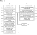
- the above-described storage unit 21 includes a connection information storage unit 21a configured to store connection information for connection to another or a plurality of other communications devices 2 and connection information for connection to the management device 3; a user authentication information storage unit 21b configured to store pieces of user authentication information such as a user ID, a password or its hash data, and the like of a user for whom access from the information terminal 7 to the communications device 2 is permitted or may be permitted; a device authentication information storage unit 21c configured to store the device authentication list listing the pieces of device authentication information needed in the authentication of the other communications device 2 and the management device 3 which may perform mutual communications with high confidentiality via the global network 1 for all the communications devices in the same group; an encryption key information storage unit 21d configured to store an encryption key or trigger information triggering generation of the encryption key and the like at the time of the device-to-device authentication and exchange of the target data; a target data storage unit 21f configured to sequentially store at least part of the target data transmitted by the transmitting-side communications device 2A or the target data received by the receiving-
- the user authentication information storage unit 21b, the device authentication information storage unit 21c, the encryption key information storage unit 21d, and the like which stores these pieces of information are provided in particular in a memory area that cannot be accessed from outside, e.g., the secret area in the memory area in the CPU.
- FIG 3 is a diagram that illustrates the data structure of the user authentication information stored in the user authentication information storage unit 21b.
- the user authentication information is constituted by the user ID and the password specified via the information terminal 7. It should be noted that the password may be stored as hashed data.
- two information terminals 7 are connected to one communications device 2 via the internal network 6, so that two pairs of the user authentication information are stored.
- Figures 4 to 7 are diagrams that illustrate the data structure of the device authentication list of the device authentication information stored in the device authentication information storage unit 21c.
- the device authentication list is stored as the same information for all of the communications device 2 and the management device 3.
- the device authentication information storage unit 21c is a data table conforming to relational database of high utility such as Oracle (TM) and MySQL (TM), etc.
- the device authentication list stored in the device authentication information storage unit 21c lists the pieces of device authentication information needed in the authentication of the respective communications devices 2 and the management device 3 for all of the communications devices 2 of the same group and the management device 3.
- the device authentication list 21c1 illustrated in Figure 4 has, as its fields, "Device ID” which indicates the initial ID, "Surname” for storing the surname of the user, "Name” for storing the name of the user, “E-Mail” for storing the e-mail address of the user, “Privilege” for storing the privilege as a general user or an administrator, "Organization” for storing the company ID (organization ID) of the company the user works with, “State” for storing the state of the user (in this example, either of valid and invalid states), and "Update Date/Time” for storing the date (and time) on which the information of the user was updated.
- the above-described e-mail address may be used as an ID when the user receives the device-to-device authentication.
- a real name is entered as the "Name” and the "Surname" stored in the device authentication information storage unit 21c but an abbreviated name derived from a project, a nickname, an online name, etc. of an individual may be entered in view of security for making it more difficult to identify the individual.
- a field that corresponds to such a name is provided.
- FIG. 5 is a diagram that illustrates the data structure of the device authentication list 21c2.
- the device authentication list 21c2 has, as its fields, "Device ID” which is an initial ID, "Switch Header” for switching passwords, "Password,” and "PW Hash Data.” Since particularly high confidentiality is required for the device authentication list 21c2, dozens to hundreds of pairs of a password and its hash data are provided for one device ID, and one pair to be used is switched at a predetermined timing by the switch header. By the device ID, a many-to-one relationship with the device authentication list 21c1 is defined in the device authentication list 21c2.
- FIG. 6 is a diagram that illustrates the data structure of the company information which is the device authentication list 21c3.
- the company information has, as its fields, "Company ID (Organization ID)" which is an initial ID and "Company Name” for storing the company name of the company ("Organization Name” for storing the organization name of the organization).
- the above-described device authentication list 21c1 has, as its field, a company ID which is the initial ID of this company information, and the device authentication list 21c1 and the device authentication list 21c3 have a many-to-one relationship.
- an abbreviated name derived from a project, a nickname, an online name, etc. of the company may be entered in the "Company Name" of the device authentication list 21c3, in the same manner as the individual name (“Surname” and "Name”) of the device authentication list 21c1 in view of security for making it more difficult to identify the actual company.
- Figure 7 is a diagram that illustrates the data structure of the group information which is the device authentication list 21c4.
- the group information has, as its fields, "Group ID” which is an initial ID, "Group Name” indicating the name of the group, "Member 1,” “Member 2,” ... “Member n” for storing the device IDs of the users belonging to this group, and "Update Date/Time” for storing the date (and the time) on which the information on this group was updated.
- the group information has the fields of "Device ID,” which is the initial ID of the device authentication list 21c1, because the information on each user to be registered in the group is to be acquired from the device authentication list 21c1, by virtue of which a many-to-one relationship is defined between the device authentication list 21c4 and the device authentication list 21c1.
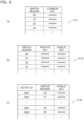
- Figure 8 is a diagram that illustrates the data structure of the encryption key information stored in the encryption key information storage unit 21d.
- the section (a) in the same figure illustrates the common key information 21d1.
- Several dozen to several hundred types of common keys are provided in advance in the common key information 21d1, amongst which one common key is selected by the switch header to be used.
- the common key is common to all of the communications devices 2 and the management device 3, but different common keys may be provided for each of the unit of management such as each party of the communications, or area and section in the same group.
- the types of the common keys to be provided increase, but the risk at the time of possible theft of the common key can be lowered.
- the section (b) of the same figure illustrates the private key/public key information 21d2. Several dozen to several hundred types of private keys/public keys are provided in advance in the private key/public key information 21d2, amongst which a certain pair is selected by the switch header to be used.
- the section (c) of the same figure illustrates the public key information 21d3 of the respective communications devices 2 and the management device 3. In the public key information 21d3, several dozen to several hundred types of public keys are provided in advance for each device ID, one of which is selected by the switch header to be used.
- the common information 21d1 and the public key information 21d3 for each of the communications devices 2 and the management device 3 the common information is stored for all of the communications devices 2 and the management device 3 while the private key/public key information 21d2 is only stored in this communications device 2 or the management device 3. Meanwhile, the public key thereof is stored in the location corresponding to the own device ID of the public key information 21d3 for each of the communications devices 2 and the management device 3.
- Figure 9 is a list of the data structure of the target data storage unit.
- the target data storage unit 21f has, as its fields, "Data ID” which is an initial ID, "Subject” for storing the subject name of the target data, "Confidentiality Level” indicative of the confidentiality level of the target data in multiple levels, "Viewing Period” indicating the period during which the target data is allowed to be viewed by a start point and an end point, "Allowable Viewing Counts” for storing the number of times for which the target data is allowed to be viewed, “Viewing Counts” for storing the number of times for which the user that has received the target data is allowed to view it on its own information terminal 7 at the time of the reception of it, where the number of times is stored in the form of a number of times remaining, "Sender” for storing the device ID of the user that has transmitted the target data, “Recipient” for storing the device ID of the user receiving the target data, "Comment” for storing the comment from the sender included in the
- the above-described confidentiality level is specified by three levels of, in the illustrated example, "Personal" (0) indicative of a low confidentiality level, "Important” (1) indicative of an intermediate confidentiality level, and "Confidential” (2) indicative of a high confidentiality level.”
- the start point of the above-described viewing period always is specified as a date and time at or after the above-described date and time of transmission.
- the start point can also be specified as a date and time after a lapse of a predetermined period of time following the date and time of transmission.
- the above-described number of allowable times of viewing can be specified within the range of one time to infinite (in the illustrated example, two levels of only once and unlimited).
- the target data storage unit 21f has, as its field, the "Device ID" field which is the initial ID of the device authentication information storage unit 21c so as to acquire the information of the user acting as the sender and the information of the user acting as the recipient from the device authentication information storage unit 21c.
- the target data storage unit 21f and the device authentication information storage unit 21c have a many-to-one relationship.
- the target data storage unit 21f in the context of the transmission and reception of the target data, the same data is individually stored in the storage unit 21 of the transmitting-side communications device 2A and the storage unit 21 of the receiving-side communications device 2B. Also, the target data whose end point of the viewing period has been reached may be deleted from the target data storage unit 21f of the storage units 21, 21 of the transmitting-side communications device 2A or the receiving-side communications device 2B.
- the OS may be a general-purpose operating system such as Windows (R) and Linux (R) or may be a proprietary dedicated OS, and alternatively multiple operating systems may be used in combination (e.g., one general-purpose OS and one dedicated OS).
- R general-purpose operating system
- R Linux
- multiple operating systems may be used in combination (e.g., one general-purpose OS and one dedicated OS).
- a dual-boot scheme may be used or a scheme may be used according to which one operating system runs on the other operating system in a virtual manner.
- Linux or the like which is a single open-source general-purpose OS is used.
- the control unit 22 includes: an encryption unit 22a configured to perform encryption of data to generate an encrypted text; a decryption unit 22b configured to decrypt the encrypted text that has been encrypted by the encryption unit 22a of the other communications device 2 to generate a plain text; an encryption key issuing unit 22c that provides an encryption key such as common key, private key, and public key for encryption and decryption; a password issuing unit 22d that provides a password for use in encryption, decryption, user authentication, or the like; a cryptographic communication unit 22e configured to perform cryptographic communications between the communications devices 2, 2 or between the communications device 2 and the management device 3; a user authentication unit 22f configured to perform user authentication to authenticate a user making an access to the communications device 2 by the information terminal 7; a device-to-device authentication unit 22v configured to perform device-to-device authentication between the communications device 2 and the other communications device 2 or the management device 3; an input/output unit 22g such as a web server providing a user interface such as a GUI(graphical user
- control unit 22 may include a communication channel selection unit 22s configured to select one communication channel from among multiple communication channels between the communications devices 2, 2 and the communication channels between the communications device 2 and the management device 3 if such multiple communication channels exist.
- the communication channel selection unit 22s may perform the communications using a GUI corresponding to the communication partner.
- the communication channel selection unit 22s can be made to function such that it selects the data transmission and reception on a normal communication channel on which the communications device 2 and the management device 3 do not reside in accordance with the IP address of the destination.
- the above-described encryption unit 22a is configured to encrypt target data or various pieces of information exchanged between the other communications devices 2, 2 using a predetermined algorithm. Also, in encryption of the target data, encryption strength is changed in accordance with the confidentiality level ("confidentiality level" of the target data storage unit 21f) specified for the same target data.
- the encryption may be performed for multiple rounds with different algorithms or different encryption keys. Also, it is also possible to use scramble processing as appropriate to split data into multiple split data pieces, modify the order of the split data pieces, and encrypt the respective split data pieces. At this point, encryption for the respective slit data pieces may be done as one round of encryption process or as multiple encryption processes. Further, different algorithms and different encryption keys may be used in different number of encryption processes depending on the split data pieces.
- the above-described decryption unit 22b decrypts the encrypted text that has been encrypted by the encryption unit 22a of the other communications device 2 using a predetermined algorithm corresponding to the algorithm of the encryption of the encryption unit 22a.
- FIG 10 is a conceptual diagram that conceptually illustrates the configurations of the encryption unit and the decryption unit.
- the encryption unit 22a includes: an input unit 22a1 configured to accept an input of a plain text (e.g., target data, etc.); an encryption unit 22a2 configured to encrypt the plain text that has been input by the input unit 22a1; and an output unit 22a3 configured to output the encrypted text (e.g., target data, etc.) that has been encrypted by the encryption unit 22a2.
- an encryption key that includes information on the encryption is provided for the encryption unit 22a2 from the above-described encryption key information storage unit 21d of the communications device 2 or by the encryption key issuing unit 22c.
- the decryption unit 22b includes: an input unit 22b1 configured to accept an input of an encrypted text (e.g., target data, etc.); a decryption unit 22b2 configured to decrypt the encrypted text that has been input by the input unit 22b1; and an output unit 22b3 configured to output the plain text (e.g., target data, etc.) that has been decrypted by the decryption unit 22b2.
- an input unit 22b1 configured to accept an input of an encrypted text (e.g., target data, etc.)
- a decryption unit 22b2 configured to decrypt the encrypted text that has been input by the input unit 22b1
- an output unit 22b3 configured to output the plain text (e.g., target data, etc.) that has been decrypted by the decryption unit 22b2.
- the encryption key provided for the encryption unit 22a2 and the encryption key provided for the decryption unit 22b2 are the same or corresponding encryption key and, specifically, they will be a combination of the same common keys or a combination of a corresponding private key and a corresponding public key.
- the encrypted text that has been encrypted by the encryption unit 22a of the transmitting-side communications device 2A is transmitted via the outbound network interface 24 of the transmitting-side communications device 2A to the receiving-side communications device 2B.
- the receiving-side communications device 2B receives the encrypted text by the outbound network interface 24 of the receiving-side communications device 2B, decrypts it by the decryption unit 22b of the receiving-side communications device 2B, and obtains a readable plain text.
- the encryption key used by one of these two communications devices 2A, 2B and the encryption key used by the other of them be the same or corresponding keys and, for example, a combination of two common keys or a combination of a private key and a public key corresponding to the same private key may be contemplated.
- this communications system multiple pairs of the same or corresponding encryption keys are stored in advance in the storage units 21, 21 of these two communications devices 2A, 2B respectively, and thus it is made possible to carry out communications in an encrypted environment immediately after the installation of the communications devices 2A, 2B.
- a password or other trigger information used in generation of the common key may be stored in advance in the storage units 21, 21 of the respective communications devices 2A, 2B in place of the common key as such.
- the common key should be generated using the same algorithm at the same timing by the respective communications devices 2A, 2B and the management device 3.
- encryption by the encryption unit 22a may be performed by multiple rounds for the same piece of data with the encryption key changed for each round of encryption, in which case the encrypted text that has been output from the output unit 22a3 is sent back to the input unit 22a1.
- the decryption unit 22b is also capable of sending the data that has been output from the output unit 22b3 back to the input unit 22b1.
- the decryption unit 22b uses the encryption key that is same with or corresponding to the encryption keys that were used in the encryption for the same piece of data that had been encrypted for multiple rounds in an inverted order which is inverted from that in the encryption to decrypt the piece of data by the same rounds, and thus the original plain text is allowed to be obtained.
- the decryption unit 22b may have "temporary decryption mode" to function such that the piece of data is automatically encrypted again upon completion of viewing and operations after the decryption.
- the common key, public key, and private key used in the encryption and decryption are stored in the encryption key information storage unit 21d as described above to be read and used as appropriate. However, it may be generated independently by the encryption key issuing unit 22c and used.
- the above-described encryption key issuing unit 22c is also capable of providing the generated encryption key to the encryption unit 22a or the decryption unit 22b or storing it in the storage unit 21.
- FIG 11 is a conceptual diagram that conceptually illustrates the configuration of the encryption key issuing unit 22c.
- the encryption key issuing unit 22c includes: an encryption key generation unit 22c1 configured to generate an encryption key; a random number generation unit 22c2 configured to generate a true random number or a pseudorandom number for use in generation of the encryption key; an information input and output unit 22c3 configured to perform input and output of information to and from the storage unit 21; and an encryption key output unit 22c4 configured to output the encryption key to be used by the encryption unit 22a and the decryption unit 22b.
- the random number generation unit 22c2 is configured to generate the true random number using uncertain information (e.g., the timing of pressing a keyboard, etc.) that is input via the input/output unit 22g or the like or generate the pseudorandom number using a password or any other definite trigger information.
- uncertain information e.g., the timing of pressing a keyboard, etc.
- a radon pulse generation device or the like may be used.
- the password is provided from the password issuing unit 22d to the random number generation unit 22c2.
- the other definite trigger information is output via the information input and output unit 22c3 from the secret area of the storage unit 21 to the random number generation unit 22c2.
- LFSR linear feedback shift register
- the encryption key generation unit 22c1 is configured to generate the encryption key on the basis of the random number from the random number generation unit 22c2 or the trigger information that has been acquired from the secret area of the storage unit 21 via the information input and output unit 22c3.
- the encryption key output unit 22c4 is configured to output the encryption key that has been generated by the encryption key generation unit 22c1 or the encryption key that has been acquired from the storage unit 21 via the information input and output unit 22c3. Meanwhile, the encryption key that has been generated by the encryption key generation unit 22c1 can be stored in the secret area of the storage unit 21 via the information input and output unit 22c3.
- the above-described password issuing unit 22d is configured to provide a password (or information of the password) used in user authentication, authentication between the communications devices 2, 2 for encrypted communication, authentication between the communications device 2 and the management device 3, generation of the above-described encryption key, and the like.
- FIG 12 is a conceptual diagram that conceptually illustrates the configuration of the password issuing unit 22d.
- the password issuing unit 22d includes: a password generation unit 22d1 configured to generate a password; a random number generation unit 22d2 configured to generate a true random number or a pseudorandom number used in generation of the password; an information input and output unit 22d3 configured to perform input and output of information to and from the storage unit 21; and a password output unit 22d4 configured to output the information of the password.
- the random number generation unit 22d2 is configured to generate a true random number using uncertain information (e.g., the timing of pressing a keyboard, etc.) that is input via the input/output unit 22g or the like or generate a pseudorandom number using definite trigger information. Also, in the generation of the true random number as well, a radon pulse generation device or the like may be used in the same manner as in the above-described case.
- the trigger information is acquired from the secret area of the storage unit 21 via the information input and output unit 22d3.
- the password generation unit 22d1 is configured to generate a password on the basis of the random number that has been generated by the random number generation unit 22d2, the trigger information that has been acquired from the secret area of the storage unit 21 via the information input and output unit 22d3, or the like.
- the password that has been generated is delivered to the password output unit 22d4 or stored in the secret area of the storage unit 21 via the information input and output unit 22d3.
- the password output unit 22d4 may receive the password from the password generation unit 22d1 and output the password, or may receive the password which a user inputs via the information terminal 7 directly from the input/output unit 22g, or may output the password that has been acquired from the secret area of the storage unit 21 via the information input and output unit 22d3.
- the password that has been output is output as needed to the respective units such as the input/output unit 22g and the encryption key issuing unit 22c.
- Encrypted communications are performed between the communications device 2 and the other communications device 2 and between the communications device 2 and the management device 3 by the above-described cryptographic communication unit 22e as illustrated in Figure 2 .
- the communications between the communications devices 2, 2 (device-to-device communications) or the communications between the communications device 2 and the management device 3 (device-to-device communication) are encrypted by the cryptographic communication unit 22e.
- the devices are VPN-connected (device-to-device-connected) to each other using protocols based on IPSec (IP Security Architecture) and PPTP (Point-to-Point Tunneling Protocol) to establish secure communication channel by tunneling and encryption.
- IPSec IP Security Architecture
- PPTP Point-to-Point Tunneling Protocol
- the encryption unit 22a and the decryption unit 22b are used in the encryption and the decryption at this point, the encryption and the decryption may be independently performed by the cryptographic communication unit 22e.
- the settings for performing the VPN connection are done in advance and do not need to be done at the time of the introduction.
- the device authentication list which is information for the authentication (device-to-device authentication) used in the encrypted communication, is stored in the device authentication information storage units 21c, 31c of the respective communications devices 2 and the management device 3. Since the device authentication list is specified at the time of shipment of the communications device 2 and stored in the storage unit 21 such that it cannot be accessed from outside, a secure scheme is implemented which ensures that leakage from a user does not occur in the operations.
- the trigger information is to be used, the timing acting as the trigger such as the setting time or transmission operation may be specified and device authentication data may be generated on the basis of the trigger information.
- connection information to connect to the other communications device 2 and the management device 3 with which exchange of data may take place is stored in advance in the connection information storage unit 21a of the storage unit 21 and does not need to be specified again at the time of the introduction of the communications device 2.
- the above-described user authentication unit 22f performs the user authentication for the user requesting access (login) to the communications device 2 using the information terminal 7 on the basis of the information stored in the user authentication information storage unit 21b of the storage unit 21 and determines whether or not the access should be permitted.
- the user authentication may be carried out using the one-time password as described above.
- leakage of the ID and/or the password may cause possible "impersonation”
- the privileges of users and disclosure information disclosed to users may be added or modified every time one of the stages of the multistage authentication proceeds.
- a sufficient number of or the maximum number of the pieces of user information are stored in advance in the device authentication information storage unit 21c as the provisional users and, when a new user is to be registered, the piece of information of one provisional user registered in the device authentication information storage unit 21c is modified and updated from the side of the management device 3 (further specifically, an information update unit 32h which will be described later).
- users to be authorized to make an access (login) by the device-to-device authentication unit 22v are limited to those whose "State" of the device authentication information 21c1 is set to "valid" (1).
- the information of the "State” is set to "invalid” (0) in the case of a provisional user.
- a sufficient number of or a maximum number of the pieces of information on the provisional companies are stored in advance in the device authentication list 21c2 which lists the pieces of company information.
- a sufficient number of or a maximum number of the pieces of group information including information on the provisional group are stored in advance in the device authentication list 21c3 which is the group information.
- the content of these pieces of information is updated by the management device 3 (further specifically, an information update unit 32h which will be described later).
- the maximum number of the provisional users are registered in advance in the provisional group.
- the maximum number of the provisional users can be declared by a person in charge of management of groups at the time of the introduction or the number of provisional users that is specified in advance can be confirmed.
- the above-described input/output unit 22g is configured to provide a GUI to the information terminal 7 of the user authorized to make an access and accepts the input from the information terminal 7.
- the input/output unit 22g is constituted by a web server or the like.
- the above-described data reception unit 22h is configured to receive the target data from the transmitting-side information terminal 7A of the user via the input/output unit 22g.
- the user acting as the sender first selects one group using the transmitting-side information terminal 7 from one or more groups to which the user himself/herself belongs. At this point, one group may be selected for each purpose of communication. Subsequently, a user (recipient) or users (recipients) to which the user wants to send the target data is selected from this group, and the number of times and period of viewing by the recipient are determined, and the target data including these pieces of information is delivered to the transmitting-side communications device 2A.
- the target data is generated individually for each user to which the target data should be sent or linked with the target data and, for example, if it is to be sent to three users, then three pieces of target data are generated or linked with the target data.
- the security strength is changed which is determined depending on the presence or absence of the encryption, the number of rounds of the encryption, and the like. It should be noted that since the communications as such are encrypted, if the confidentiality level is lowest, then it is also possible to omit the encryption of the target data as such.
- the above-described data transmission unit 22i transmits the target data that has been encrypted by the encryption unit 22a to the receiving-side communications device 2B of the receiving-side information terminal 7B of the user designated as the destination.
- the transmission processing for transmitting target data by the data transmission unit 22i may be performed immediately or the transmission processing may be carried out after the lapse of the start point of the viewing period.
- the above-described data reception unit 22k is configured to receive the target data from the transmitting-side communications device 2A.
- the target data that has been received by the data reception unit 22k is an encrypted text that has been encrypted as described above
- the target data is decrypted by the decryption unit 22b into a plain text.
- the same or corresponding encryption key as that in the encryption is used for the decryption.
- the decryption will be able to be carried out promptly and accurately if the data reception unit 22k of the receiving-side communications device 2B receives the confidentiality level of the target data from the data transmission unit 22i of the transmitting-side communications device 2A. Meanwhile, it is not essential to exchange the information on the confidentiality level between the two communications devices 2A, 2B as long as the rule is defined in advance in accordance with the confidentiality level.
- the necessary information in the target data which is now in the form of a plain text is stored in the target data storage unit 21f of the storage unit 21 of the receiving-side communications device 2B.
- the above-described data distribution unit 221 distributes the target data to the receiving-side information terminal 7B in response to a request from the receiving-side information terminal 7B of the user specified as the recipient of the target data. It should be noted that the data distribution unit 221 may spontaneously carry out the distribution of the target data to the receiving-side information terminal 7B at a predetermined timing. Meanwhile, the distribution by the data distribution unit 221 is only allowed to be carried out when the viewing is not regulated (prohibited) by the viewing regulation unit 22m.
- the above-described viewing regulation unit 22m regulates (prohibits) the distribution of the target data to the receiving-side information terminal 7B of the user specified as the recipient: if the number of times of viewing (remaining) of the target data is set to 0; if the current time is out of the viewing period; if number of times of viewing (remaining) during which viewing is prohibited by the sender is indicated by a symbol of prohibition such as ⁇ ; if the system administrator of the management device 3 has received the application for prohibition of viewing from a person in charge of management of groups; or if the viewing is prohibit in view of the management of the system administrator.
- the start point and the end point are specified for the viewing period and the interval demarcated by the start point and the end point becomes the period during which viewing is possible.
- This start point can be specified at the time point at which the transmitting-side information terminal 7A delivers the data to the transmitting-side communications device 2A, or at the time point after a lapse of a predetermined period of time after the former time point. In the latter case, the recipient will be allowed to view the target data after the lapse of the above-described predetermined period of time after the sender transmitted the target data.
- the above-described cancellation unit 22j performs the cancellation processing when a request for cancellation of the transmission (distribution) of the target data has been sent from the transmitting-side information terminal 7A, where the cancellation processing is performed on the side of the transmitting-side communications device 2A. Specifically, if the target data is yet to be transmitted by the data transmission unit 22i prior to the start point of the viewing period, then deletion of the target data stored in the storage unit 21 of the transmitting-side communications device 2A or cancellation of the transmission processing is performed, so that the distribution is canceled.
- the target data stored in the storage unit 21 of the receiving-side communications device 2B is remotely deleted or the distribution processing as such of the target data on the side of the receiving-side communications device 2B is canceled, and thus the distribution is canceled. If a copy of the target data is created, the copied target data should be deleted as well.
- whether or not the cancellation instruction is an authentic one may be determined using hash data or the like. Specifically, for example, a common hash program and a common key are held in a confidential state between the transmitting-side information terminal 7A and the receiving-side information terminal 7B.
- the transmitting-side information terminal 7A combines the cancellation instruction code and the common key with the cancellation instruction to hash it and then send it to the receiving-side information terminal 7B.
- the receiving-side information terminal 7B upon reception of the cancellation instruction, combines the cancellation instruction code with the common key to hash them, and compares what has been hashed with the received hash value and, if they agree with each other, determines that the cancellation instruction code is not falsified and that the cancellation instruction has been legitimately issued by the transmitting-side information terminal 7A. Also, at this point, the user authentication may be performed again to confirm whether or not the cancellation instruction is the one that has been issued from a user having a correct authorization.
- the user having the correct authorization hereinafter simply referred to as "user"
- a person in charge of management of groups, or a person in charge of group registration may be contemplated.
- the system administrator needs to check if these persons in charge are the persons themselves registered using documentation of personal identity (a car driver's license with photo, etc.).
- the cancellation processing from the transmitting-side communications device 2A it is made possible to respond to a case where erroneous target data has been distributed and thereby increases the usability.
- the distribution at issue can be cancelled by the similar processing.
- a deletion flag or any other like element may be included in the data at the time of transmission thereof, and the deletion flag may be disabled in normal cases such that the data erasure takes place when it is taken out of the disabled state and enabled.
- the above-described packet control unit 22n is configured to control the communications performed via the two network interfaces 23, 24.
- the information terminal 7 located in the internal network 6 to which the communications device 2 pertains carries out the communication via the external network 1, then the communication always takes place via the communications device 2 in accordance with the above-described network configuration, so that the communication (packet) from the information terminal 7 passes through the communications device 2.
- the communication packet originating from the information terminal 7 and reaching the inbound network interface 23 is transferred via the outbound network interface 24 to the router 4, and then sent to the external network 1 by the router 4.
- the communications device 2 is capable of acquiring not only the communication history of the communications device 2 but also the communication history of the information terminal 7 on the side of the internal network 6, and controls the communication packet in this manner by the packet control unit 22n.
- the packet control unit 22n can also control communication packets to cause the communications device 2 to function as a router, in addition to which the packet control unit 22n can control the communication packets to enable a firewall with respect to the side of the inbound network interface 23 to be configured and enable a firewall with respect to the side of the outbound network interface 24 to be configured.
- the packet control unit 22n when used, it is made possible to respond, to a certain extent in real time, to DoS attacks, etc. on the IKE used in the VPN connection, and such information can also be analyzed by the history analysis unit 22p.
- the above-described history information accumulation unit 22o is configured to sequentially store, in the communication history information storage unit 21g of the storage unit 21, communication history of the above-described communications device 2, a history of communication via the external network 1 of the information terminal 7 pertaining to the internal network 6 to which the communications device 2 pertains, or a history of the access communication to the communications device 2, which are stored as communication history. Also, the history information accumulation unit 22o sequentially stores the sensing results of various sensors such as the GPS sensor 25, the acceleration sensor 26, and the gyro sensor 27 as sensing information (sensing history information), which are stored sequentially in the sensing information storage unit 21h of the storage unit 21.
- the above-described history analysis unit 22p is configured to carry out the analysis of the communication history. Specifically, the history analysis unit 22p analyses ordinary operating statuses based on the communication history at this time and the communication history stored in the history information accumulation unit 22o, where the operating statuses including workdays for each organization constituting the internal network 6 (e.g., a company as such or a predetermined department or section of this company, etc.) and status of attendance of each user, and sequentially stores the results of the analysis in the history analysis information storage unit 21i. It should be noted that the above-described DoS attacks and other attacks from outside can be recognized by this analysis.
- the history analysis unit 22p may automatically discriminate the information terminal 7 of the user making an access to the communications device 2 on the basis of the above-described operating status and sequentially store the result as the analysis results in the history analysis information storage unit 21i.
- the normal state of the communications device 2 is analyzed on the basis of the results of the detection of states acquired from the GPS sensor 25, the acceleration sensor 26, and the gyro Sensor 27 and the information on the sensing history stored in the sensing information storage unit 21h and the results of the analysis may be stored in the history analysis information storage unit 21i of the storage unit 21.
- the communications device 2 may be configured such that it allows communications only in a predetermined time interval or may be connected to a particular sensor used in IoT (a temperature sensor, human sensor, various sensors such as that for sensing of an ID card, and a surveillance camera, etc.).
- the above-described abnormality determination unit 22q is configured to determine an abnormal state of the communications device 2 on the basis of the sensing result and result of analysis of the communication history.
- the abnormality determination unit 22q determines that an abnormality has occurred considering the possibility of theft or the like. Specifically, first, at the time of the introduction of the communications device 2, the position information at the time of the initial power-on is recognized as the installation position of the communications device 2. Subsequently, if the position information that has been acquired by the GPS sensor 25 or the most recent position information stored in the sensing information storage unit 21h is different from the installation position, then the determination of the abnormality is performed and, if the position information is in agreement with the installation position, then the determination of normality is performed.
- the sensing history of the GPS sensor 25 or the analysis information thereof or the like may be acquired from the sensing information storage unit 21h or the history analysis information storage unit 21i to compare them with these pieces of information and thus the error in the sensing of the GPS sensor 25 can be corrected to a considerable degree.
- abnormality determination unit 22q determines that an abnormality has occurred when the fact that the attitude of the communications device 2 connected to the PC was changed or the fact that a load is acting thereon has been detected by the gyro Sensor 27 and the acceleration sensor 26, considering the possibility of theft or the like. Specifically, when the attitude information or the load information that has been acquired by the gyro Sensor 27 or the acceleration sensor 26 or the most recent attitude information or load information stored in the sensing information storage unit 21h takes an abnormal value different than a normal one, then the determination that an abnormality occurs is made while the determination that a normal state exists is made otherwise.
- the attitude information or the load information stored in the sensing information storage unit 21h or the analysis information on the attitude information or the load information stored in the history analysis information storage unit 21i is used, it is made possible to increase the accuracy of the determination on normality or abnormality.
- the communications device 2 has moved due to an earthquake or fire, the sensor information associated therewith is notified to the management device 3 for performing the response at the time of occurrence of an abnormality.
- the response at the time of occurrence of an abnormality may encompass notification to all the users belonging to the group and stoppage or suspension or the like of the communications by the corresponding communications device 2.
- the communications device 2 operates when it has passed the time code of the time authentication or the authentication check instructed to the terminal, and stops its operation when an abnormality has occurred.
- the authentication check is performed by image authentication by a camera, fingerprint authentication, and voice authentication, which are used alone or in combination.
- the abnormality determination unit 22q uses the analysis information of the communication history stored in the history analysis information storage unit 21i and performs determination of normality and abnormality based on the past or current communication history acquired from the two network interfaces 23, 24 and the communication history information storage unit 21g. Specifically, the determination of normality and abnormality regarding the unauthorized access, unauthorized operation, overload, and the like is performed on the basis of the access from the information terminal 7 of the user and the operation status associated with the access, an access from an information terminal 7 of a company, department/section, user, etc. expected to be on a holiday and the operation status associated with the access, presence or absence of abnormal rise in the load away from the normal load, and the like. Also, the communication histories of all the communications devices 2 are periodically sent to the management device.
- the above-described communication regulation unit 22r regulates (prohibits) exchange of data and communications via the communications device 2 in which the abnormality has been determined to exist.
- the communication is regulated in this manner, then the above-described exchange of the target data will also be prohibited.
- the communications devices 2 other than the communications device 2 in which the abnormality has been determined to exist maintain their communication functions in an unregulated state and it is possible to cause them to continue the transmission and reception of the target data within the same group. It should be noted that when an abnormality associated with unauthorized access or unauthorized operation has been determined to exist, then switching of the passwords, encryption keys, and the like may be allowed to be carried out in place of the above-described communication regulation or along with the communication regulation.
- the communications device 2 configured as described in the foregoing can also be made to function as the transmitting-side communications device 2A and can also be made to function as the receiving-side communications device 2B.
- the data reception unit 22h, the data transmission unit 22i, and the cancellation unit 22j are functional components dedicated to the transmitting-side unit while the data reception unit 22k and the data distribution unit 221 are functional components dedicated to the receiving-side unit.
- the communications device 2 when the communications device 2 is used as a dedicated device for the transmitting-side communications device 2A, it is possible to omit the functions dedicated to the receiving-side while when the communications device 2 is used as a dedicated device for the receiving-side communications device 2B, it is possible to omit the dedicated functions for the transmitting-side.
- FIG 13 is an explanatory diagram that illustrates the configuration of the management device 3.
- the management device 3 illustrated in the same figure includes: a storage unit 31 constituted by the memory area including the secret area in the CPU, RAM, ROM, HDD, SSD and the like and configured to temporarily or permanently store various pieces of information; a control unit 32 constituted by the CPU, RAM, SSD, etc. and configured to execute various programs; and a network interface (communications unit) 33 connected to the external network 1 (specifically, the router 4).
- a storage unit 31 constituted by the memory area including the secret area in the CPU, RAM, ROM, HDD, SSD and the like and configured to temporarily or permanently store various pieces of information
- a control unit 32 constituted by the CPU, RAM, SSD, etc. and configured to execute various programs
- a network interface (communications unit) 33 connected to the external network 1 (specifically, the router 4).
- the storage unit 31 includes: a connection information storage unit 31a having the same or substantially the same configuration as that of the connection information storage unit 21a; a user authentication information storage unit 31b having the same or substantially the same configuration as that of the user authentication information storage unit 21b; a device authentication information storage unit 31c having the same or substantially the same configuration as that of the device authentication information storage unit 21c; an encryption key information storage unit 31d having the same or substantially the same configuration as that of the encryption key information storage unit 21d; and a target data storage unit 31f having the same or substantially the same configuration as that of the target data storage unit 21f.
- unnecessary pieces of information may be omitted as needed and, for example, the communication history information storage unit (not shown), the sensing information storage unit (not shown), and the history analysis information storage unit (not shown) correspond to the data tables that can be omitted
- a user registered in the user authentication information storage unit 31b of the storage unit 31 becomes a system administrator who can access to the management device 3 using the information terminal (not shown) on the side of the management device 3 or the information terminal 7 on the side of the communications device 2.
- the user who succeeded in accessing the management device 3 is allowed to freely acquire information by which an individual can be identified, then everything leaks out.
- the management device 3 is provided by a provider providing the services of this communications system.
- the system administrator who manages the management device 3 is either a provider or a person entrusted directly from the provider.
- the access to the user authentication information storage unit is redundantly checked by another system administrator and that all the management histories are recorded and a scheme for disclosure of the management histories of the management device 3 by the system administrator may be adopted as needed.
- Connection information for performing encrypted communications with the respective communications devices 2 to be managed ID information, the same or corresponding encryption key or password or trigger information triggering generation of them, and the like are stored in the connection information storage unit 31a, the device authentication information storage unit 31c, and the encryption key information storage unit 31d in the storage unit 31.
- the above-described control unit 32 realizes various functions by programs that run on the operating system.
- the units to be used by the OS are the same or substantially the same as those of the above-described control unit 22.
- the control unit 32 includes: an encryption unit 32a having the same or substantially the same configuration as those of the encryption unit 22a; a decryption unit 32b having the same or substantially the same configuration as those of the decryption unit 22b; an encryption key issuing unit 32c having the same or substantially the same configuration as those of the encryption key issuing unit 22c; a password issuing unit 32d having the same or substantially the same configuration as those of the password issuing unit 22d; a cryptographic communication unit 32e having the same or substantially the same configuration as those of the cryptographic communication unit 22e; a user authentication unit 32f having the same or substantially the same configuration as those of the user authentication unit 22f; a device-to-device authentication unit 32v having the same or substantially the same configuration as those of the device-to-device authentication unit 22v; and an input
- control unit 32 includes, independently of these units: an information update unit 32h configured to update predetermined information of the storage unit 21 of the respective communications devices 2 to be managed; and a restoration processing unit 32i.
- an information update unit 32h configured to update predetermined information of the storage unit 21 of the respective communications devices 2 to be managed
- a restoration processing unit 32i configured to restore the information of the storage unit 21 of the respective communications devices 2 to be managed.
- the above-described information update unit 32h is configured to update the information of the communications device 2 to be managed. Specifically, when encrypted communications are performed between the communications devices 2, 2 or when the exchange of the target data through the external network 1 via these communications devices 2, 2 is performed, at least part of the connection information, the user authentication information, the device authentication information, and the encryption key information which these communications devices 2, 2 individually store in their storage units 21, 21 in advance needs to be made to be identical with or to correspond to each other to share at least part of them, and the synchronization of the information for that purpose is performed by the information update unit 32h. Also, the synchronization of the information is also necessary between the communications device 2 and the management device 3, so that this synchronization processing is likewise carried out by the information update unit 32h.
- the information update unit 32h replaces the information on the provisional users, company information, or the group information of the user authentication information storage unit 21b and the device authentication information storage unit 21c in the respective storage units 21 of the respective communications devices 2 to be managed or the communications devices 2A, 2B which are parties of the communications with each other to be managed by each other by actual data requested by the person in charge of management of groups after determination thereof. More specifically, the information update unit 32h encrypts the actual data using the common key or public key and transmits all at once the encrypted data via the communication line to the respective communications devices 2.
- the processing of changing the "Status” of the same user to “valid” (1) is performed in parallel, while in the deletion of the user information, the processing of changing the "Status” of the user to "temporarily invalid” (0) or “permanently invalid” (000) is performed.
- the user changed to "invalid” becomes the above-described provisional user and the user changed to "permanently invalid” (000) becomes an irrevocably invalid user.
- one or more communications devices 2 may further reside on the communication channel between the transmitting-side communications device 2A and the receiving-side communications device 2B using the information update unit 32h.
- a list of the IP addresses of the communications devices to be received on the communication channel is included in the transmission data and, when the respective communications devices have received the data, then the IP addresses are rewritten to be addressed to the next communications device and transmission thereof may be repeated.
- the communications between the interconnected communications devices 2, 2 are encrypted using the same scheme as that in the above-described embodiment.
- the above-described restoration processing unit 32i carries out the processing to release the communication regulation for the communications device 2 in the state where communications are regulated by its own communication regulation unit 22r. Incidentally, the restoration processing by the management device 3 is carried out after the state where the regulation of the communications can be released has been confirmed.
- Figure 14 is a flow diagram that illustrates the processing procedures of the user authentication and the device-to-device authentication in exchanging data by this communications system.
- the provider of the communications device 2 stores in advance information necessary for confidential communications in the storage units 21, 31 specified in the secret areas of the CPUs of the communications device 2 and the management device 3.
- the information includes provisional information regarding the users and groups which will be added in the future.
- the information concealed and stored in advance is the device authentication lists 21c1 to 21c4 and the encryption key information 21d1 to 21d3.
- the users of the information terminals 7A, 7B specify the user Id and the password in the communications devices 2A, 2B.
- the user ID and the password are also stored in the user authentication information storage unit 21b of the storage unit 21.
- the communications device 2 hashes the password using SHA-224, SHA-256, SHA-384, SHA-512, etc. and stores the pair of the user ID and the hashed password in the storage unit 21 of the communications device 2.
- the operation to be performed by the user only involves entry of the user ID and setting of the password.
- the registration information of the device authentication information storage unit 31c is allowed to be viewed by all the users registered in the group except for the confidential information such as the password, encryption key, to be concealed or the trigger information triggering generation of them, or the like.
- the user first activates the information terminal 7 and enters the user ID and the password or its hash data.
- the user activates the GUI and enters the user ID and the password or its hash data via the transmitting-side information terminal 7A.
- the transmitting-side communications device 2A compares the user ID and the password or its hash data which are stored with the user ID and the password or its hash data which have been entered and, when they agree with each other, determines that the user authentication is successful and places the information terminal 7 or the GUI in the login state. It should be noted that address information of part of the registered users is displayed on a GUI imitating an envelope.
- the transmitting-side communications device 2A encrypts the device ID and the password (or password hashed by SHA-224, SHA-256, SHA-384, SHA-512, etc.) of the destination user using a common key or a public key of the management device 3 and transmits them along with the switch header of the encryption key to the management device 3 in order to perform device-to-device authentication with the receiving-side communications device 2B via the management device 3.
- the management device 3 decrypts the device ID and the password that have been received using the common key specified by the switch header or the private key of the management device 3 and carries out the device-to-device authentication of the sender and the recipient on the basis of the registered information of the device authentication information storage unit 31c and transmits the result of authentication to the receiving-side communications device 2B.
- the receiving-side communications device 2B performs authentication of the transmitting-side communications device 2A, in response to the result of authentication from the management device 3.
- the authentication can be performed by the same or similar procedure as in VPN connection as described above. For example, data combining the message necessary for the authentication, the common key, and its switch header is hashed to generate a message authentication code (HMAC), and the message and the message authentication code are transmitted and received between the transmitting-side communications device 2A and the receiving-side communications device 2B.
- HMAC message authentication code
- the common hash programs are shared by the transmitting-side communications device 2A and the receiving-side transmission device 2B, and the message authentication code that has been generated from the received message and the message authentication code that has been received are compared with each other, and if they agree with each other, it is determined that the device-to-device authentication has been successful. It should be noted that the switch header of the hash programs is transmitted when the common hash programs are switched to be used.
- the target data to be exchanged may encompass various types such as sensing data, programs and commands for machine control or sequence control, data, etc., as well as document data, still image data, video data, voice, music, e-mail data, and FTP data.
- the user can change the password of the device ID and the encryption key stored in the device authentication information storage unit 21c and the encryption key information storage unit 21d at an appropriate timing, in which case, the switch header is transmitted by the information update unit 32h between the communications devices 2, 2 and between the communications device 2A and the management device 3 and thereby the switch header can be shared in real time.
- the switch header is transmitted by the information update unit 32h between the communications devices 2, 2 and between the communications device 2A and the management device 3 and thereby the switch header can be shared in real time.
- a one-time password or one-time encryption key can be generated using the encryption key issuing unit 22c and the password issuing unit 22d and transmitted using the common key so as to share the one-time password or one-time encryption key in the same group.
- the transmitting-side information terminal 7A delivers the target data to the transmitting-side communications device 2A via the input/output unit 22g of the transmitting-side communications device 2A (S101).
- the transmitting-side communications device 2A receives the target data by the data reception unit 22h (S102) and encrypts the target data that has been received by the encryption unit 22a (S103). Specifically, the transmitting-side communications device 2A encrypts, for example, the header information section which includes the information on communication control, authentication, and encryption appended to the data body of the target data and the like using a public key of the receiving-side communications device 2B and encrypts the data body using a common key. At this point, the header information section should include the switch header for the common key and the public key of the receiving-side communications device 2B.
- Strength is selected for this encryption process in accordance with the confidentiality level. For example, if the confidentiality level is low (e.g., the case of "Personal"), the encryption is not performed and only the scrambling process of the redivision and relocation process is performed; if the confidentiality level is intermediate (e.g., the case of "Important"), one round of the encryption process is performed; and, if the confidentiality level is high (e.g., the case of "Confidential"), multiple rounds of the encryption process are performed. In the case of multiple encryption processes, one of these multiple processes may use a disclosed public key while the remaining ones use a concealed private key, or different encryption algorithms may be used in the encryption processes.
- the encrypted data may be further encrypted or the scrambling process of the redivision and rearrangement may be used to perform encryption on each of the divided pieces of data as described above using the same or different algorithms and/or encryption keys. It should be noted that, since the communications as such are encrypted, no plain text will be exchanged even when the encryption is not performed in the step S103.
- the target data that has been encrypted in this manner is transmitted by the data transmission unit 22i of the transmitting-side communications device 2A to the receiving-side communications device 2B (S104).
- the receiving-side communications device 2B receives the target data by the data reception unit 22k (S105) and decrypts the target data that has been received by the decryption unit 22b (S106). Specifically, the header information section of the received target data is decrypted using a private key and the main body of the target data is decrypted using a common key.
- the encryption key used in the encryption of the target data is stored in advance in the encryption key information storage unit 21d of the transmitting-side communications device 2A and the storage unit 21 of the receiving-side communications device 2B as common data or corresponding data, and the encryption key is shared, and settings using these pieces of information have been already done, so that it is not necessary to make various settings at the time of the introduction associated with encryption and decryption, in addition to which transmission and reception of the common key and the public key will not be required, either.
- the confidential information necessary for encryption and decryption of the target data may be shared as needed between the respective communications devices 2 and the management device 3. Further, it is also possible to update in real time and share these pieces of information by the above-described information update unit 32h between the communications devices 2, 2 and between the communications device 2A and the management device 3.
- encryption and decryption take place for multiple rounds in accordance with the confidentiality level but the information on what kind of encryption should be performed in accordance with the confidentiality level needs to be grasped by the party performing the decryption as well.
- a possible scheme for the recognition thereof is that the information is encrypted and included in the header information or the scheme for encryption and decryption is defined in advance in the communications device 2.
- the information on the confidentiality level of the target data is needed, and this information is exchanged in the course of the direct or indirect exchange between the transmitting-side communications device 2A and the receiving-side communications device 2B. Specifically, this exchange will be carried out at the time of the operation using the GUI of the Figures 12 and 14 which will be described later.
- the target data that has been decrypted in this manner is distributed by the data distribution unit 221 of the receiving-side communications device 2B to the receiving-side information terminal 7B of the user (S107).
- the distribution is allowed to take place only in the viewing period of the target data and only when the number of times of viewing remaining is not 0.
- the distribution is regulated by the viewing regulation unit 22m.
- the data distribution unit 221 performs the processing for decrementing the number of times of viewing of the target data by one (1) at each rounds of the distribution process in cases other than the case where the allowable number of times of the viewing of the target data is specified as "Unlimited" (specifically, cases where a finite value is specified).
- the receiving-side information terminal 7B receives the target data from the receiving-side communications device 2B (S108).
- the same number of pieces of target data as that of the destinations are generated on the side of the transmitting-side communications device 2A and the processes at and after the encryption step (S103) are performed on each of the pieces of target data.
- the respective communications devices 2 identify not only the management device 3 but also the communications device 2 as a party to be involved in the communication, which are specified as early as the time of the system introduction, but this communication configuration may be adapted to be updated in real time by the information update unit 32h.
- the respective communications devices 2 and the management device 3 may hold a connection list or the like in the connection information storage unit 21a such that this list is to be updated.
- the password issuing unit 22d is activated to generate a one-time password, and a request is sent to the receiving-side communications device 2B to urge it to activate the encryption key issuing unit 22c. Since the one-time password is different from the password of the user, it is generated as a new password for each round of transmission.
- the encryption key generated by the receiving-side communications device 2B is a private key, and the public key is generated from this private key. Subsequently, the public key that has been generated is encrypted using a common key and transmitted to the transmitting-side communications device 2A.
- the transmitting-side communications device 2A decrypts the public key of the receiving-side communications device 2B using the common key, and encrypts the target data using the public key that has been decrypted, and places the target data that has been encrypted in the state where opening thereof is restricted using the one-time password.
- the data obtained by combining the opening-restricted target data and the one-time password is encrypted using the common key.
- the receiving-side communications device 2B decrypts the received target data using the common key and extracts the one-time password from the data that has been decrypted to open the target data. Further, it decrypts, using the private key, the header information section of the target data that has been opened and decrypts the body section using the common key.
- the common key may be generated by the encryption key issuing unit 22c.
- the common key is encrypted by a public-key scheme and then transmitted to the other party. Specifically, the following process is performed.
- Figure 16 is an explanatory diagram that illustrates a configuration of a group top screen, which is a form of a GUI.
- the group top screen 71 illustrated in Figure 16 is displayed as the GUI.
- the group top screen 71 includes: a sharing member display section 71a in which names (full name) of one or more users belonging to this group are acquired from the device authentication information storage unit 21c and displayed in the form of a list; a received data display operation section 71b (indicated as "In-Box”) on which an operation (click operation) is performed which triggers acquisition of pieces of target data that the user who has logged in received as the group, which are acquired from the target data storage unit 21f and displayed in the form of a list; a transmitted data display operation section 71c (indicated as "Out-BOX”) on which an operation (click operation) is performed which triggers acquisition of the pieces of target data that the user who has logged in transmitted as the group, which is acquired from the target data storage unit 21f and displayed in the form of a list; and a transmission screen display operation section 71d (indicated as "New envelope”) on which an operation (click operation) is performed which triggers display of the transmission screen 72 (see Figure 17 ) for the user who has
- FIG 17 is an explanatory diagram that illustrates the configuration of the transmission screen, which is a type of a GUI.
- the transmission screen 72 includes: a subject entry unit 72a in which "Subject" of the target data storage unit 21f is entered (indicated as "Envelope Name”); a viewing period input section 72b in which the "viewing period” of the target data storage unit 21f is entered; a confidentiality level entry unit 72c in which the "confidentiality level" (indicated as "Transmission Level") of the target data storage unit 21f is entered (in the illustrated example, either of the "Personal” radio box, the "Important” radio box, and the "Confidential” radio box is selected); an allowable viewing counts entry unit 72d in which the "allowable viewing counts" of the target data storage unit 21f is entered (in the illustrated example, a checkbox is provided which sets the allowable viewing counts to one (1) so that only one time or unlimited is selected by presence or absence of the check in it); an address designation section 72e in which
- Figure 18 is an explanatory diagram that illustrates the configuration of the target data display screen.
- the target data display screen 73 displays the content of the target data and it is displayed on the same screen as that of the transmission screen 72 so as to constitute part of the GUI.
- the target data display screen 73 imitates an envelope which is a postal item, and includes: a subject display section 73a in which the "Subject"(in the illustrated example, "Envelope Name") of the target data storage unit 21f is displayed; a sender display section 73b in which the name (full name) of the "sender” of the target data storage unit 21f is displayed; a transmission date and time display section 73c in which the "transmission date and time” of the target data storage unit 21f is displayed; a confidentiality level display section 73d in which the "confidentiality level" (indicated as "Transmission Level") of the target data storage unit 21f is displayed; a viewing count display section 73e in which the "number of times of viewing” of the target data storage unit 21f is displayed; a destination display section 73f in which the "recipients" (users as the destinations) of the target data storage unit 21f are displayed in the form of a list of full names, abbreviated names, on-line
- the target data display screen 73 may be configured as a screen imitating a slip as well as a postal item, and a screen imitating a postal item and a screen imitating a slip may be selected.
- a screen is described which imitates a vertically long postal item but it may be a horizontally long postal item, or one screen may be selected from among a screen imitating a vertically-elongated postal item, a screen imitating a horizontally-elongated item, and a screen imitating a slip.
- undefined information is indicated as a blank field.
- the transmission date and time is yet to be defined at the time of the entry into the transmission screen 72, it is indicated by "****" or as a blank field.
- a transmission button 72h is displayed in the above-described transmission screen 72 and when the transmission button 72h is clicked, transmission (delivery processing) of the target data from the transmitting-side information terminal 7A is actually carried out.
- the target data display screen 73 is displayed, in which case the actual date and time are indicated as the transmission date and time.
- a viewing history display section 73k in which viewing history of the recipient is indicated is displayed in the above-described target data display screen 73. It should be noted that at the time of checking of the transmitted target data as well, the viewing history display section 73k can be displayed, but in order for the display, it is necessary to synchronize the pieces of information stored in the target data storage unit 21f between the transmitting-side communications device 2A and the receiving-side communications device 2B, and this synchronization processing may be carried out by the above-described information update unit 32h.
- GUIs illustrated in Figures 17 and 18 may be provided as dedicated interfaces for each group. In this case, the GUIs are foolproof and very user-friendly, for they vary depending on the groups.
- the multifactor authentication may be implemented with much more factors.
- an additional authentication factor based on position information acquired by the GPS sensor 25 may further be added. Specifically, when it has been detected by the GPS sensor 25 that the communications device 2 is out of its original position where it should be found, the access by the user authentication is denied or the device-to-device connection by the device-to-device authentication is denied.
- position information on the business trip areas and countries such as business trips to domestic areas and foreign countries may be used in the course of the user authentication and a response may be made when the device is not found in the authorized areas.
- the encryption processing based on multiple factors to perform multiple encryption processes redundantly is also performed at the time of the encryption and decryption of the target data. Specifically, an encryption process that the user performs using the GUI from the information terminal 7A is used on one hand and an encryption process for the device-to-device communication is used on the other hand.
- this communications system can be introduced in various business areas.
- this communications system can be used in exchange of data among a customer, a design company and a printing company, and exchange of data among a customer, a design company, a magazine company or a newspaper company, and a printing company or a newspaper factory.
- this communications system can be used in the patent business areas or other legal or financial affairs often dealing with confidential information under confidentiality obligation, and in exchange of drawing data, translation data, or other confidential information, or in exchange of data with foreign countries.
- information terminal 7 as a module in a built-in camera of a digital camera or smartphone to share data photographed among a plurality of cameras; share data captured via PCs with each other; and achieve implementation using this in communications such as telephone, net meeting or videoconferencing system, online shopping system, etc. with the bandwidth of the network line secured.
- the process to deliver the data to the data reception unit 22h needs to be automatically performed by an application or the like.
- the target data still image data, video data, or sound data acquired by a camera or microphone for video conferences, or still image data or video data captured by a monitoring camera.
- the information terminals 7A, 7B may be incorporated into the camera and/or microphone.
- the authentication will proceed as follows. First, the surveillance camera is connected via the communications device 2 to, for example, an external network 1 (the Internet) complying with 5G (fifth-generation) specifications.
- a user accesses his/her own information terminal 7 (personal computer) using his/her user ID and password and selects the registered ID of the surveillance camera from the slip GUI for the same surveillance camera, and thus the communications device 2 connected to his/her own information terminal 7 performs the device authentication on the communications device 2 of the surveillance camera via the management device 3.
- the user can watch or record the video of the surveillance camera using his/her own information terminal 7.
- this communications system may be used in communication between a traffic control center that controls and manages traffic lights and an automobile. Furthermore, based on the maneuvering management information, abnormal driving information, and road and area information in the automatic driving of automobiles, an information management center etc. of a road management corporation etc. may prompt a driver for attention, provide information for safe driving, or safely perform provision of data to automotive driving devices.
- this communications system can also be used in: transmission and reception of data between government offices and municipalities; transmission and reception of data between branch offices or between a branch office and a head office of a company; transmission and reception of data between project members within a company; transmission and reception of electronic medical records in a medical facility; transmission and reception of important information such as electronic medical records, confidential information, and collaborative design plans over a wide area; online manuscript submission; electronic PO Box service; and the like.
- construction is performed under information management by multiple groups of multiple companies, such as basic design, procurement of building materials, purchase cost management, personnel arrangement for construction sites, construction progress status, shared complaint information, legal documents to be submitted. Even those in charge who are unfamiliar with information management can perform information transmission safely while keeping the information in this construction project secret without the need of being aware of the security management.
- the communications device 2 may be coupled to a heavy object such as a safe to prevent physical theft.
- At least one communications device 2 in this communications system may include an information update unit (not shown) and a restoration processing unit (not shown) having the same or substantially the same configurations as those of the information update unit 32h and the restoration processing unit 32i of the management device 3. By virtue of this, it is made possible to omit the management device 3.
- “Guest Transmission User” who is entitled to perform transmission and reception temporarily or continuously or perform transmission only, and “Guest Reception User” who is entitled to perform reception temporarily or continuously for a limited period of time may be provided.
- a guest transmission user and a guest reception user are users who are given the privilege to access the communications device 2 temporarily.
- “Time-Limited Sender” is entered in the privilege field of the guest transmission user and "Time-Limited Recipient” is entered in the privilege field of the guest reception user.
- the registration of the "Guest Transmission User” or the “Guest Reception User” is performed by the user of the communications device 2 submitting the electronic application to the system administrator via the "person in charge of management of groups.”
- the system administrator sends a notification of the permission to the "person in charge of management of groups” and the user of the communications device 2, and performs the registration to the GUIs of all members of the same group, and a time-limited password is given to the "Guest Transmission User” or the "Guest Reception User.”
- the "Guest Transmission User” or the “Guest Reception User” is disclosed on the device authentication list as well.
- the device authentication information storage unit 21c may include the fields of "Time-Limited Privilege" for an administrator, a general user, a guest transmission user, and a guest reception user.
- the administrator may be allowed to have a function to give permission for transmission, reception, and information updates to other users within a company (intra-organization management function).
- such a special privilege may be allowed to be separately entered in the field of "Special Privilege” and a user having such a special privilege may be handled as "Special User" to increase the types of users.
- Permission to transmit or receive the target data may be granted for each user belonging to the group or may be granted to the group as a whole.
- permission by a general user or a person in charge of management of groups may also be required in the setting of the above-described guest transmission user or the guest reception user.
- a connection device 28 may be provided which includes an external storage medium connected removably to the body of the communications device 2, a token, or other information terminals or the like having communication function such as a camera, a smartphone, and a tablet device.
- the connection device 28 includes a connection information storage unit 28a, a user authentication information storage unit 28b, a device authentication information storage unit 28c, and an encryption key information storage unit 28d, which have the same or substantially the same configurations as those of the above-described connection information storage unit 21a, the user authentication information storage unit 21b, the device authentication information storage unit 21c, and the encryption key information storage unit 21d, respectively.
- connection information storage unit 28a, the user authentication information storage unit 28b, the device authentication information storage unit 28c, and the encryption key information storage unit 28d includes the various pieces of information that have been added to, modified in, or deleted from storage unit 21.
- the control unit 22 sets a pre-announcement period, a post-announcement period, or the like on the basis of these pieces of addition, modification, or deletion information, and it is thus made possible to: perform modification and/or deletion of pieces of information on the privileges of the new user and existing users and other information; modification of the information on the new group and the existing groups; addition of new connection-destination communications device 2; or modification and/or deletion of the connection information of an existing communications device 2.
- a user By incorporation of such a function, it is made possible for a user to change and update the network configuration, the user information, the group information, and the like in a state where the time and labor of the settings on the user-side communications device 2 are reduced.
- a general user, a guest transmission user, or a guest reception user in a certain group is allowed to create at any time one or more new groups on their own accord and it is also possible for the user to act as a general user in the new group.
- a user belonging to one group and having the privilege to submit an application for addition of a new user to the same group is defined as the "person in charge of group registration.”
- the person in charge of group registration submits the electronic application to the system administrator using the public key and common key transmitted from the system administrator of the management device 3.
- the system administrator decrypts the incoming application form within the management device 3 and transmits the device ID and the full name of the new user, and the device authentication list which includes the additional information of the new user including the state switched to "valid" and the information on the deletion of the member user to all the communications devices 2 of the group for which the application was submitted via the management device 3.
- the system administrator of the management device 3 may also transmit the hash data of the device authentication list to the communications device 2 of the group so as to prevent falsification of data by checking the device authentication list at the time of operation of the management device 3.
- the person in charge of group registration submits an electronic application for addition of the new user to the system administrator.
- the system administrator to which the electronic application has been submitted performs filtering and virus check on the additional information on the new user and, if no problem has been found, performs the encryption processing thereon and registers it in the device authentication list of the management device 3.
- the communications device 2 hashes the password to store it along with the user ID in the storage unit 21.
- the person in charge of group registration submits an electronic application for deletion of the user to the system administrator.
- the system administrator sets the header information of the information on the user for which the application was submitted in the device authentication list such that the header information indicates "communication prohibited” and registers the modification along with the date and time in the device authentication list. It is ensured that all the users in the group are allowed to view the device authentication list that has been updated except for the confidential information.
- the envelope GUI is displayed with part of the destination information updated.
- a user in the group submits an electronic application for new group registration to the system administrator.
- a certificate indicating that the communications device 2 is introduced by all the users in the group is attached to the electronic application.
- the system administrator performs filtering and virus check on the information on all the users of the group for which the electronic application was submitted and, if no problem has been found, registers the information on the new group in the device authentication list of the management device 3.
- the registration is performed by identifying the group ID and the device ID of the provisional group and the provisional user and switching from the invalid state to the valid state.
- the communications device 2 hashes the password and stores it in the user authentication information storage unit 21b of the storage unit 21. It is ensured that all the users in the group are allowed to view the device authentication list that has been updated except for the confidential information. This is also displayed as partial destination information on the envelope GUI.
- the system administrator of the management device 3 encrypts the update information of the device authentication list, specifically, the enabled group ID and device ID and notifies them to all the users belonging to the same group including the user newly registered in the same group.
- a user belonging to this group and performing management of the same group may be defined as "a person in charge of management of groups.”
- the device authentication list including the information on addition or deletion of a user to or from the group may be double-checked by the person in charge of group registration and the person in charge of management of groups.
- the application includes the information on the companies, section names, addresses, names, commonly used names, and contacts of the main users constituting this group.
- a person in charge of management of groups can urge users having the same type of the communications device 2 to join the new group.
- a guest ID is used for accessing their respective communications devices 2.
- Tasks associated with the addition of a new group, addition of a user in a group, or applications therefor can be performed by simple attachment and detachment of the connection device 28 provided with the additional information already specified by the system administrator.
- the connection device 28 provided with the additional information already specified by the system administrator.
- it is made possible to provide the extensibility of the network structure, and redundancy in the user configuration and the group configurations.
- the connection device 28 may include the control unit 22, the network interfaces 23, 24, and various information detection sensors 25, 26, 27 of the communications device 2. In this case, it is made possible to use it as a backup device at the time of malfunctioning of the communications device 2.
- the control unit of the connection device 28 acquires its own position by means of the GPS sensor and determines that the communications device 2 is out of its original position where it should be located if the acquired position is not found within a certain range (zone), and determines by the abnormality determination unit 22q that an abnormality has occurred. Also, it may be determined by the abnormality determination unit 22q that an abnormality has occurred when any use out of the original use time has been detected by a timer provided in the device itself. Further, in order to determine whether or not the person is really authorized to use the connection device 28, the person may be requested to enter the password or pass biometric authentication using fingerprints, veins, or the like, face authentication, voice authentication, or the like.
- dummy information may be included in addition to the original data (e.g., target data, etc. which will be hereinafter referred to as “true data") in the data to be exchanged in the communications between the communications device 2 and the management device 3 or between the communications devices 2, 2.
- false data can be readily included in the data exchanged as described above in a state where the false data cannot be distinguished from the true data, which enhances the security.
- sensing information or sequence control information for controlling an IoT device in the data exchanged as described above.
- M2M information which includes information collected from pieces of equipment and information for controlling the equipment.
- remote operation such as teleoperation etc. can be achieved by exchange of information with an IoT device incorporating the information terminal 7 and connected to the communications device 2 or incorporating the communications device 2.
- a piece of operation equipment(control equipment) incorporating the information terminal 7 and a piece of actuation equipment incorporating the information terminal 7 are connected to each other via the network 1, the operation equipment and the actuation equipment also incorporate the communications devices 2, 2 or are connected thereto, to function as an IoT device and an M2M device, respectively, and share their sensing information and sequence information with each other through mutual communications.
- the operation equipment and the actuation equipment are each configured to be capable of exchanging data with the data reception unit 22h and the data distribution unit 221 of the communications device 2.
- the user causes the personal computer or mobile terminal for use in data acquisition to acquire his/her own sensor or camera information continuously to connect to the information terminal 2 using the user ID and the password.
- device authentication is performed on one or more communications device 2 connected to the IoT equipment via the communications device 2 connected to or integrated in his/her own IoT personal computer or mobile terminal or a management device function incorporated in a SIM card integrated into the management device 3 or mobile terminal.
- the specific authentication procedure is as described above. When the authentication has been normally performed, then the pieces of data are acquired successively by his/her own IoT personal computer or mobile terminal and the pieces of data are stored if necessary.
- virus check is performed on the data exchanged in the communications between the communications device 2 and the management device 3 or between the communications devices 2, 2, by the communications device 2 or the management device 3 on the transmitting side or the receiving side, and if a virus has been detected, the data as such is discarded or deletion of the virus from the data is performed. Further, the communications device 2 or the management device 3 on which the virus check has been performed may send back the data from which the above-described virus has been deleted to the transmission source or may notify the presence of the virus to the transmission source.
- the processes of the virus check or deletion of the virus can be performed not only by a dedicated monitoring server installed in a domestic area or overseas area but also by consigning the processes to a service company specialized in virus check. In addition to this, the processes may be delegated to an existing domestic or overseas virus check server to reduce the processes. Also, for reduction in the burden of the virus check process and other processes described above, multiple management devices 3 may be provided such that various processes are assigned to them.
- the recovery procedure in the case where it has been determined by the abnormality determination unit 22q that an abnormality occurred has been described by way of an example where the recovery procedure is performed by the management device 3, but the recovery work can also be done by this communications system as a whole. Specifically, when the above-described determination confirming the occurrence of the abnormality has been made, the occurrence of the abnormality is notified to all the communications devices 2 that manage the same group.
- authenticated user of the communications device 2 on which the abnormality occurred obtains permission from the system administrator of the management device 3 or any other person in charge of management of groups such as the boss of the user and confirms the permission information by the connection device 28 or by means of personal authentication such as biometric authentication on the system administrator or the person in charge of management of groups and carries out the recovery work upon confirmation of the same information.
- the network administrator of this communications system who is going to permit the recovery at issue indicates his/her intention to do so by the connection device 28 or by means of personal authentication such as biometric authentication and, upon confirmation of this intention, the authenticated user of the communications device 2 on which the abnormality occurred sends the application information requesting the recovery to the system administrator having the administrator privilege on the management device 3.
- the system administrator of the management device upon reception of the application form, performs the recovery work to recover the communications device 2 and notifies the recovery to all the communications devices 2 having the information on the same group as the group stored in this communications device 2.
- viewing by even the administrator may be prohibited such that, when a general user has stored the encrypted target data, which was encrypted by the above-described GUI on the information terminal 7, in the storage unit 21 of the communications device 2, then provision of the privilege to access the target data is limited to the general user who has performed the encryption and a general user who receives the same target data.
- hash data may be used.
- target data and its hash data or destination information and its hash data may be used.
- general-purpose PC equipment or general-purpose communication terminals incorporating a storage device or a memory card in which the communication program is stored may be used as the communications device 2.
- group authentication to use this group may be performed. Specifically, a particular part or all pieces of the information of the user belonging to one group should be entered and the communication using this group is only allowed to be performed when the correct information has been entered.
- the users may be sorted in accordance with their attributes such as country, area, age, man/ woman, hobby, and the like within the group to create subgroups or the like.
- GUI imitating a slip can be used in slip entry in Internet shopping, etc. Specifically, it will be convenient to automatically output a piece of information that appear to be identical (e.g., information of the purchaser) among the pieces of information entered in the past from the stored pieces of data such that only pieces of information such as purchase date, service name, product name, unit price, and total price need to be newly entered.
- this communications system can be applied to concealed calls using voice data as the target data.
- two communications devices 2, 2 are interposed between two information terminals 7, 7 on which the telephone application is installed, and streaming encryption is applied to the device-to-device communication between these two communications devices 2, 2 to perform encryption of voice data to be transmitted and received between two (or among three or more) information terminals 7,7.
- this communications system can be used for concealed e-mails.
- dedicated GUIs such as an envelope are used on a per-group basis to encrypt the target data such as e-mail and an attached file and subject part or all of the pieces of target data to masking processing on data subdivision scrambling processing and color conversion processing which are reversibly performed and transmit and receive the processed data via the device-to-device communication.
- this communications system can be applied to electronic medical records. Specifically, masking processing is performed on the portion corresponding to the personal information of the electronic medical record to store it in a cloud server connected to the external network 1 and viewing, addition, modification, and deletion thereof are performed via the communications device 2 when the viewing is necessary.
- this communications system can be used as countermeasures for prevention of lost articles.
- a GPS sensor terminal is used as the transmitting-side information terminal 7A so as to be capable of wireless communications with a portable transmitting-side communications device 2A, and the GPS sensor terminal is secured to the user's item such as a bag.
- the smartphone owned by the user the GPS position information of the user is always transmitted to the cloud server and the like, and when the GPS position information transmitted from the transmitting-side information terminal 7A via the transmitting-side communications device 2A does not agree with the user's GPS position information, it may be determined that the user's item is remote from the user, and this fact may be notified.
- a seismic sensor, a surveillance camera, a vital check sensor, a measuring instrument, and/or other sensors may be incorporated in the IoT equipment having the transmitting-side information terminal 7A or the information terminal function for encryption and decryption of the captured data and sensing information between the two communications devices 2, 2 or between pieces of the IoT equipment so as to transmit them to the receiving-side information terminal 7B.
- notification of the abnormality is performed.
- the notification of the abnormality may be issued from the transmitting-side information terminal 7A or may be issued from the receiving-side information terminal 7B. Further, as needed, data may be subjected to the masking processing to conceal part of the information.
- a personal computer or a smartphone of a user may be defined as the communications terminal 7, and a communications device 2 such as a modular IC memory device and USB memory device may be attached to the communications terminal 7 to encrypt transmission and reception of information with an on-line bank, a mail-order company, and a company or individual providing the service of escrow. Also, client information may be managed in a separate manner between a company providing the service of escrow and a mail-order company may be independently and implement countermeasures against information leakage.
- a communications device 2 such as a modular IC memory device and USB memory device may be attached to the communications terminal 7 to encrypt transmission and reception of information with an on-line bank, a mail-order company, and a company or individual providing the service of escrow.
- client information may be managed in a separate manner between a company providing the service of escrow and a mail-order company may be independently and implement countermeasures against information leakage.
- the connection is established in order of: the transmitting-side communications device 2A --> the communications device 2 (or the management device 3) --> ... --> the communications device 2 (or the management device 3) --> the receiving-side communications device 2B.
- the two devices adjacent to each other are provided with device authentication information such as the same or corresponding ID and password, and encryption key or trigger information triggering generation of them, which are specified and stored in the storage area that cannot be accessed from outside such as the secret are defined in the CPU from among the storage units 21 of the communications device 2 and the storage units 31 of the management device 3 in advance at the time of shipment or the like by the system administrator such that they can perform encrypted communication with each other.
- multiple pairs of the user information and the confidential information may be stored in advance so as to be changed at a predetermined timing or by a predetermined trigger information.
- the exchange of the target data is carried out by the data transmission unit 22i and the data reception unit 22k of the communications device 2, or by the data transmission unit (not shown) and the data reception unit (not shown) having the same or substantially the same configurations as those of the data transmission unit 22i and the data reception unit 22k provided in the management device 3, and the communication channel which finally reaches the destination is held by the respective communications devices 2 or the management device 3.
- FIG. 19 is a flow diagram that illustrates the processing procedure of the exchange of the target data in a communications system according to another embodiment.
- the management device 3 includes a data reception unit (not shown), a data distribution unit (not shown) and a viewing regulation unit (not shown) having the same or substantially the same configurations as those of the data reception unit 22h, data distribution unit 221 and the viewing regulation unit 22m, respectively, and the respective communications devices 2 includes a relay data reception unit 22t and a relay data transmission unit 22u configured to relay the target data to the management device 3.
- the ID or the password for performing device-to-device authentication, encryption keys for encryption and decryption or the trigger information triggering generation of these keys are shared between the transmitting-side communications device 2A and the management device 3, and, between the management device 3 and the receiving-side communications device 2B.
- the management associated with the individual identifiable information should be implemented more strictly. Specifically, when an access is made to the management device 3, authentication that can identify individuals such as fingerprint authentication, voice authentication, face authentication, etc. is performed, and the access logs are stored as well.
- massage about maintenance information, group modification information, fees and the like may be sent from the management device 3 to the information terminal 7 of the user using this communications system. Further, advertisement information or questionnaire information, and the like may be transmitted from the management device 3. Also, in view of the fact that the connection information concentrates at the management device 3, one or more file servers (not-shown) configured for backup or mirroring of data of the management device 3 may be independently provided.
- the transmitting-side information terminal 7A passes the target data to the management device 3 via the input/output unit 32g of the management device 3 (S201).
- the transmitting-side communications device 2A forcibly receives the target data sent toward the management device 3 by the relay data reception unit 22t (S202), and encrypts the target data that has been received by the encryption unit 22a (S203), and transmits the target data that has been encrypted by the relay data transmission unit 22u to the management device 3 (S204).
- the management device 3 receives the encrypted data by the data reception unit (S205), and decrypts it by the decryption unit 32b of the management device 3 (S206).
- the device authentication list (device ID and password, etc.) for performing device-to-device authentication and encryption keys for performing, encryption and decryption or trigger information triggering generation of these keys are stored in advance in the storage units 21, 31 and shared between the transmitting-side communications device 2A and the management device 3.
- the decryption may only be performed on the minimum number of pieces of data needed in the transfer (e.g., only the header information for device authentication), in addition to which the target data may not be decrypted at all and the header information necessary for the transfer may be separately received from the transmitting-side communications device 2A.
- the target data will not be able to be confirmed on the side of the management device 3, so that the leakage of data from the side of the management device 3 is prevented and thus the security is further enhanced.
- the management device 3 encrypts the target data by the encryption unit of the management device 3 (S207) and distributes the encrypted target data by the data distribution unit of the management device 3 to the receiving-side communications device 2B arranged on the side of the receiving-side information terminal 7B (S208). It should be noted that, as described in the foregoing, when not all of the pieces of target data are decrypted, the data is sent on an as-is-basis to the receiving-side communications device 2B.
- the receiving-side communications device 2B receives the distributed target data using the relay data reception unit 22t (S209) and decrypts the received target data by the decryption unit 22b of the receiving-side communications device 2B (S210).
- the ID, the password, the encryption keys or trigger information for triggering generation of these for performing encryption and decryption are stored in advance in the storage units 21, 31 and shared between the management device 3 and the receiving-side communications device 2B.
- the receiving-side communications device 2B transmits the above-described decrypted target data to the receiving-side information terminal 7B by the relay data transmission unit 22u (S211).
- the receiving-side information terminal 7B receives the transmitted target data (S212).
- the respective communications devices 2 has only to implement sharing of the connection information to connect to the management device 3 and confidential information for encryption or authentication, and these pieces of information can be managed integrated manner on the side of the management device 3. Also, the same applies also to the user information, the group information, and the company information. Incidentally, regardless of the fact that the information terminal 7 is engaged in exchanging information with the management device 3, the information during the exchange is automatically relayed by the communications device 2 and encrypted, almost no time or labor of users is required.
- the communications device 2 and the management device 3 do not need to maintain the device-to-device connection permanently.
- the connection between them can be limited to the initial communication.
- one or more different communications devices 2 or management devices 3 may reside between the transmitting-side communications device 2A and the management device 3, and between the management device 3 and the receiving-side communications device 2B according to the above-described scheme.
- the management device 3 relays all pieces of data and has functionality covering part of those of the transmitting-side communications device 2A and the receiving-side communications device 2B of the above-described mode, so that it can function as a cloud server.
- the communications device 2 may be configured such that it is connected to the side of the management device 3 when the user attempts to connect to the communications device 2 using the information terminal 7. In this case, the user is allowed to exchange data via the management device 3 without being aware of the management device 3.
- the decryption process (S206) and the encryption process (S207) by the management device 3 may be omitted to reduce the processing load.
- the information of the receiving-side communications device 2B and the receiving-side information terminal 7B distributing the target data should be directly acquired from the transmitting-side communications device 2A or the transmitting-side information terminal 7A.
- the transmitting-side information terminal 7A accesses the transmitting-side communications device 2A and the transmitting-side communications device 2A accesses the management device 3.
- the receiving-side information terminal 7B accesses the receiving-side communications device 2B and the receiving-side communications device 2B accesses the management device 3.
- FIG 20 is an explanatory diagram that illustrates an outline of a communications system according to another embodiment of the present invention.
- a relaying terminal 8 configured to relay communications of the information terminal 7 with the communications device 2 is provided in the internal network 6.
- Information on the relay channel is held by the relaying terminal 8 as a relay table 8a.
- the relaying terminal 8 in one internal network 6 is connected to the relaying terminal 8 in another internal network 6 via a connection line 9.
- the communications device 2 on the side of the one internal network 6 breaks down, the information terminal 7 on the side of the one internal network can use the communications device 2 on the side of the other internal network as a substitute.
- Addition, modification, deletion, and the like of the relay channel is performed in accordance with an instruction from the management device 3 of the system administrator, the information terminal 7 of a person in charge of management of each group, or the like through addition, modification, deletion, or the like of information to, in, or from the relay table 8a of the relaying terminal 8.
- an information terminal 7 in one internal network 6 and an information terminal 7 in another internal network 6 may be connected via a connection line 9'.
- relaying terminal 8 can be replaced by the information terminal 7.
- FIG 21 is an explanatory diagram that illustrates an outline of the group configuration according to another embodiment of the present invention.
- a new group or a new user can be added by the external connection device 28 or in accordance with the above-described update scheme, by virtue of which, operation that abound in redundancy can be enabled.
- one group A is created by a user "a” and three users “b,” “c,” and “d” are added into the group A, and these three users “b,” “c,” and “d” create the groups B, C, and D, respectively, and a user "g” put into the group C crates the group G.
- FIG 22 is an explanatory diagram that illustrates the configuration of the communications device according to a different embodiment of the present invention.
- the control unit 22 further includes a hacking prevention unit 22w.
- the hacking prevention unit 22w is configured to: periodically change the port used in the communication; periodically urge users to change their passwords; automatically update the operating systems and software programs to keep them up to data so as to prevent hacking. It should be noted that the hacking prevention unit 22w may be provided in the control unit 32 of the management device 3 so as to prevent hacking on the management device 3.
- FIG 23 is an explanatory diagram that illustrates an outline of the communications system according to a different embodiment of the present invention.
- the information terminal 7 includes a device that transmits and receives various pieces of data of a personal computer, smartphone, and tablet terminal operated by the user as well as IoT equipment, M2M equipment, camera, robot, remote operation equipment, automobile, AI equipment, and the like and, for example, constituted by an IoT terminal capable of wireless communications with the communications device 2, or a device capable of wireless communications with the communications device 2 configured to perform sensing by a sensor, and machine-controlled.
- the communications device 2 may transmit commands for controlling the IoT equipment, M2M equipment, camera, robot, remote operation equipment, AI equipment, and the like to control these devices.
- the network 9 may be a global network, may be a private network, or may be a network configured by combining them.
- the one information terminal 7 is capable of cryptographic communication via a pair of communications devices 2, 2 with the other information terminal 7. As a result, it is made possible to share the sensing information of all the information terminals 7 to use it as big data, it is made possible for the one information terminal 2 to monitor the sensing information from the other information terminal 7, or it is also made possible to machine-control the information terminal 7.
Landscapes
- Engineering & Computer Science (AREA)
- Computer Security & Cryptography (AREA)
- Signal Processing (AREA)
- Computer Networks & Wireless Communication (AREA)
- Computer Hardware Design (AREA)
- General Engineering & Computer Science (AREA)
- Computing Systems (AREA)
- Theoretical Computer Science (AREA)
- Software Systems (AREA)
- General Physics & Mathematics (AREA)
- Physics & Mathematics (AREA)
- Power Engineering (AREA)
- Data Exchanges In Wide-Area Networks (AREA)
- Telephonic Communication Services (AREA)
- Computer And Data Communications (AREA)
Claims (12)
- Système de communication permettant à une pluralité de terminaux d'information (7) inclus dans un même groupe d'échanger des données les uns avec les autres via un réseau mondial (1), le système de communication comprenantla pluralité de terminaux d'information (7), etune pluralité de dispositifs de communication (2) chacun connecté à chacun des terminaux d'information (7) dans le groupe de sorte à établir une communication mutuelle de haute confidentialité entre la pluralité de terminaux d'information (7) inclus dans le groupe, dans lequella pluralité de terminaux d'information (7) inclut un premier terminal d'information (7A) et un deuxième terminal d'information (7B),la pluralité des dispositifs de communication (2) inclut un premier dispositif de communication (2A) et un deuxième dispositif de communication (2B),le premier terminal d'information (7A) établit des communications avec le réseau mondial (1) via le premier dispositif de communication (2A),le deuxième terminal d'information (7B) établit des communications avec le réseau mondial (1) via le deuxième dispositif de communication (2B),se caractérisant en ce quele premier dispositif de communication (2A) inclut une unité de stockage (21) stockant de premières informations d'authentification d'utilisateur (21b) requises pour une authentification d'un utilisateur du premier terminal d'information (7A) et une liste d'authentification de dispositifs (21c) incluant un identificateur (ID) de dispositif et un mot de passe des dispositifs de communication dans le système de communication requis pour une authentification de tous les dispositifs de communication (2) dans le groupe incluant le premier dispositif de communication (2A) et le deuxième dispositif de communication (2B), la liste d'authentification de dispositifs est pré-stockée dans l'unité de stockage (21) dans un état où la liste d'authentification de dispositifs est inaccessible depuis l'extérieur du système de communication,le deuxième dispositif de communication (2B) inclut une unité de stockage (21) stockant des deuxièmes informations d'authentification d'utilisateur (21b) requises pour une authentification d'un utilisateur du deuxième terminal d'information (7A) et la liste d'authentification de dispositifs (21c), la liste d'authentification de dispositifs est pré-stockées dans l'unité de stockage (21) du deuxième dispositif de communication (2B) dans un état où la liste d'authentification de dispositifs est inaccessible depuis l'extérieur du système de communication,le premier dispositif de communication (2A) est configuré pour exécuter, lorsqu'un échange de données est effectué entre le premier terminal d'informations (7A) et le deuxième terminal d'information (7B) via le réseau mondial (1), un premier processus d'authentification d'utilisateur, le premier processus d'authentification d'utilisateur est exécuté entre le premier dispositif de communication (2A) et le premier terminal d'information (7A) en utilisant les premières informations d'authentification d'utilisateur et une entrée d'informations vers le premier terminal d'information (7A) par l'utilisateur du premier terminal d'information (7A),le deuxième dispositif de communication (2B) est configuré pour exécuter, lorsqu'un échange de données est effectué entre le premier terminal d'informations (7A) et le deuxième terminal d'information (7B) via le réseau mondial (1), un deuxième processus d'authentification d'utilisateur, le deuxième processus d'authentification d'utilisateur est exécuté entre le deuxième dispositif de communication (2B) et le deuxième terminal d'information (7B) en utilisant les deuxièmes informations d'authentification d'utilisateur et une entrée d'informations vers le deuxième terminal d'information (7B) par l'utilisateur du deuxième terminal d'information (7B), etle premier dispositif de communication (2A) et le deuxième dispositif de communication (2B) sont configurés pour exécuter le processus d'authentification de dispositif-à-dispositif lorsque l'échange de données est effectué entre le premier terminal d'information (7A) et le deuxième terminal d'information (7B) via le réseau mondial (1), le processus d'authentification de dispositif-à-dispositif est exécuté entre le premier dispositif de communication (2A) et le deuxième dispositif de communication (2B) en se référant à la liste d'authentification de dispositifs,dans lequel lorsque la première authentification d'utilisateur est terminée, le premier dispositif de communication (2A) est configuré pour effectuer la transmission de l'ID de dispositif et le mot de passe au deuxième dispositif de communication (2B) afin d'exécuter l'authentification de dispositif-à-dispositif avec le deuxième dispositif de communication (2B).
- Le système de communication selon la revendication 1, comprenant en outre un dispositif de gestion (3) connecté au réseau mondial (1) et configuré pour exécuter au moins en partie le processus d'authentification de dispositif-à-dispositif entre le premier dispositif de communication (2A) et le deuxième dispositif de communication (2B), lorsque l'échange de données est effectué entre le premier terminal d'information (7A) et le deuxième terminal d'information (7B) via le réseau mondial (1), dans lequella liste d'authentification de dispositifs répertorie des éléments d'informations d'authentification de dispositifs nécessaires à l'authentification du dispositif de communication (2) et du dispositif de gestion (3) par rapport à tous les dispositifs de communication (2) et la totalité des dispositifs de gestion (3) dans le même groupe, et inclut des ID et des mots de passe de dispositif des dispositifs de communication (2) et des dispositifs de gestion (3) dans le système de communication, etle dispositif de communication (2) et le dispositif de gestion (3) disposent d'une unité de stockage (21, 31) pré-stockant la liste d'authentification de dispositifs dans un état où la liste d'authentification de dispositifs est inaccessible depuis l'extérieur du système de communication.
- Le système de communication selon la revendication 1 ou 2, dans lequella liste d'authentification de dispositifs inclut des informations d'authentification de dispositif incluant un ID de dispositif et un mot de passe d'un utilisateur valide de chacun des dispositifs de communication déjà enregistrés dans le groupe, et des informations d'authentification de dispositif incluant un ID de dispositif et un mot de passe d'un utilisateur provisoire prédéfini pour un dispositif de communication non enregistré (2) dans le groupe ; etle dispositif de communication (2) active l'ID de dispositif et le mot de passe de l'utilisateur provisoire lorsqu'un nouvel utilisateur est enregistré dans le groupe, et notifie l'ID de dispositif activé de l'utilisateur à l'intégralité des dispositifs de communication (2).
- Le système de communication selon la revendication 2, dans lequella liste d'authentification de dispositifs inclut des informations d'authentification de dispositif incluant un ID de dispositif et un mot de passe d'un utilisateur valide de chacun de dispositifs de communication déjà enregistrés (2) dans le groupe et des informations d'authentification de dispositif incluant un ID de dispositif et un mot de passe d'un utilisateur provisoire prédéfini pour un dispositif de communication non enregistré (2) dans le groupe ; etle dispositif de gestion ou le dispositif de communication (2) active l'ID de dispositif et le mot de passe de l'utilisateur provisoire lorsqu'un nouvel utilisateur est enregistré dans le groupe, et notifie l'ID de dispositif activé de l'utilisateur à l'intégralité des dispositifs de communication (2).
- Le système de communication selon l'une quelconque des revendications 1 à 4, dans lequella liste d'authentification de dispositifs inclut un nom de groupe provisoire prédéfini pour un groupe non enregistré et des informations d'authentification de dispositif incluant un ID de dispositif et un mot de passe d'un utilisateur provisoire inclus dans le nom de groupe provisoire ; etlorsqu'un nouveau groupe est enregistré, le dispositif de communication (2) réécrit le nom de groupe provisoire en un nom de groupe réel, active un ID de dispositif et un mot de passe d'au moins certains des utilisateurs provisoires du nom de groupe réel, et notifie le nom de groupe réel réécrit et l'ID de dispositif des utilisateurs activés au dispositif de communication (2) de l'utilisateur activé du nouveau groupe.
- Le système de communication selon la revendication 2 ou 4, dans lequella liste d'authentification de dispositifs inclut un nom de groupe provisoire prédéfini pour un groupe non enregistré et des informations d'authentification de dispositif incluant un ID de dispositif et un mot de passe d'un utilisateur provisoire inclus dans le nom de groupe provisoire ; etlorsqu'un nouveau groupe est enregistré, le dispositif de gestion (3) ou le dispositif de communication (2) réécrit le nom de groupe provisoire en un nom de groupe réel, active un ID de dispositif et un mot de passe d'au moins certains des utilisateurs provisoires du nom de groupe réel, et notifie le nom de groupe réel réécrit et l'ID de dispositif des utilisateurs activés au dispositif de communication (2) de l'utilisateur activé du nouveau groupe.
- Le système de communication selon l'une quelconque des revendications 1 à 6, dans lequel au moins une partie d'une clé de chiffrement pour établir une communication chiffrée entre les dispositifs de communication (2) ou d'informations de chiffrement pour chiffrer une génération de la clé chiffrée est stockée dans l'unité de stockage du dispositif de communication (2) dans un état où l'au moins une partie est inaccessible depuis l'utilisateur.
- Le système de communication selon l'une quelconque des revendications 2, 4 et 6, dans lequel au moins une partie d'une clé de chiffrement pour établir une communication chiffrée entre les dispositifs de communication (2) et entre les dispositifs de communication (2) et le dispositif de gestion (3) ou d'informations de déclenchement pour déclencher une génération de la clé de chiffrement est stockée dans l'unité de stockage du dispositif de gestion (3) dans un état où l'au moins une partie est inaccessible depuis l'utilisateur.
- Le système de communication selon l'une quelconque des revendications 1 à 8, dans lequel le dispositif de communication inclut :une unité d'authentification d'utilisateur (22f) configurée pour déterminer si une autorisation d'accès doit ou non être accordée en réaction à une demande d'accès issue du terminal d'information (7) selon des informations d'authentification d'utilisateur stockées dans l'unité de stockage (21) ;une unité d'authentification de dispositif à dispositif (22v) configurée pour exécuter un processus d'authentification de dispositif-à-dispositif avec l'autre dispositif de communication (2) selon une liste d'authentification de dispositifs stockée dans l'unité de stockage (21) ;une unité d'entrée/sortie (22g) configurée pour entrer et sortir des informations de et vers un terminal d'information auquel une autorisation d'accès est accordée par l'unité d'authentification d'utilisateur (22f) ; etune unité de transmission/réception de données (22h, 22i) configurée pour exécuter une transmission et une réception de données avec l'autre dispositif de communication (2) authentifié par l'unité d'authentification de dispositif-à-dispositif (22v).
- Le système de communication selon l'une quelconque des revendications 1 à 9, dans lequel le dispositif de communication (2) inclut :une unité d'analyse d'historique (22p) configurée pour analyser un historique de communication stocké selon les besoins dans l'unité de stockage (21) ; etune unité de détermination d'anormalité (22g) configurée pour déterminer un accès non autorisé ou une opération non autorisée selon un état de fonctionnement au quotidien du dispositif de communication (2) analysé par l'unité d'analyse d'historique (22p).
- Le système de communication selon l'une quelconque des revendications 1 à 10, dans lequel le dispositif de communication inclut un capteur de position (25) et est configuré pour déterminer si le dispositif de communication (2) est ou non situé à une position où le dispositif de communication (2) devrait être initialement utilisé en se référant à des informations de position acquises auprès du capteur de position (25).
- Le système de communication selon la revendication 9, dans lequel l'unité d'entrée/sortie (22g) est configurée pour présenter au terminal d'information (7) un écran de saisie de données imitant un article postal ou une enveloppe en tant qu'interface utilisateur.
Priority Applications (1)
| Application Number | Priority Date | Filing Date | Title |
|---|---|---|---|
| EP23184671.8A EP4231591A3 (fr) | 2016-06-29 | 2017-06-29 | Système de communication, dispositif de communication utilisé dans celui-ci, dispositif de gestion et terminal d'informations |
Applications Claiming Priority (2)
| Application Number | Priority Date | Filing Date | Title |
|---|---|---|---|
| JP2016128381 | 2016-06-29 | ||
| PCT/JP2017/023940 WO2018003919A1 (fr) | 2016-06-29 | 2017-06-29 | Système de communication, dispositif de communication utilisé dans celui-ci, dispositif de gestion, et terminal d'information |
Related Child Applications (2)
| Application Number | Title | Priority Date | Filing Date |
|---|---|---|---|
| EP23184671.8A Division EP4231591A3 (fr) | 2016-06-29 | 2017-06-29 | Système de communication, dispositif de communication utilisé dans celui-ci, dispositif de gestion et terminal d'informations |
| EP23184671.8A Division-Into EP4231591A3 (fr) | 2016-06-29 | 2017-06-29 | Système de communication, dispositif de communication utilisé dans celui-ci, dispositif de gestion et terminal d'informations |
Publications (3)
| Publication Number | Publication Date |
|---|---|
| EP3481004A4 EP3481004A4 (fr) | 2019-05-08 |
| EP3481004A1 EP3481004A1 (fr) | 2019-05-08 |
| EP3481004B1 true EP3481004B1 (fr) | 2023-08-16 |
Family
ID=60787289
Family Applications (2)
| Application Number | Title | Priority Date | Filing Date |
|---|---|---|---|
| EP17820273.5A Active EP3481004B1 (fr) | 2016-06-29 | 2017-06-29 | Système de communication, dispositif de communication utilisé dans celui-ci, dispositif de gestion, et terminal d'information |
| EP23184671.8A Pending EP4231591A3 (fr) | 2016-06-29 | 2017-06-29 | Système de communication, dispositif de communication utilisé dans celui-ci, dispositif de gestion et terminal d'informations |
Family Applications After (1)
| Application Number | Title | Priority Date | Filing Date |
|---|---|---|---|
| EP23184671.8A Pending EP4231591A3 (fr) | 2016-06-29 | 2017-06-29 | Système de communication, dispositif de communication utilisé dans celui-ci, dispositif de gestion et terminal d'informations |
Country Status (4)
| Country | Link |
|---|---|
| US (2) | US11082423B2 (fr) |
| EP (2) | EP3481004B1 (fr) |
| JP (3) | JP7152765B2 (fr) |
| WO (1) | WO2018003919A1 (fr) |
Families Citing this family (23)
| Publication number | Priority date | Publication date | Assignee | Title |
|---|---|---|---|---|
| JP2019054466A (ja) * | 2017-09-15 | 2019-04-04 | 株式会社 エヌティーアイ | 通信システム、第1通信装置、第2通信装置、方法、コンピュータプログラム |
| US10887351B2 (en) * | 2018-05-02 | 2021-01-05 | NortonLifeLock Inc. | Security for IoT home voice assistants |
| JP6846381B2 (ja) * | 2018-05-31 | 2021-03-24 | 株式会社日立製作所 | 接続デバイス制限システム |
| JP7164333B2 (ja) * | 2018-06-27 | 2022-11-01 | 株式会社日立製作所 | 個人情報分析システム |
| JP7262964B2 (ja) * | 2018-10-12 | 2023-04-24 | 株式会社東芝 | 情報処理装置、及び情報処理システム |
| US11374958B2 (en) * | 2018-10-31 | 2022-06-28 | International Business Machines Corporation | Security protection rule prediction and enforcement |
| JP7273523B2 (ja) * | 2019-01-25 | 2023-05-15 | 株式会社東芝 | 通信制御装置および通信制御システム |
| GB2582978B (en) | 2019-04-12 | 2022-05-04 | Nchain Holdings Ltd | Methods and devices for propagating blocks in a blockchain network |
| CN111262834B (zh) * | 2020-01-09 | 2022-03-29 | 中国信息通信研究院 | 物理实体的认证、可信解析方法、装置及系统 |
| JP7058687B2 (ja) * | 2020-04-27 | 2022-04-22 | ソフトバンク株式会社 | システム、通信デバイス、プログラム、及び通信方法 |
| US11363041B2 (en) | 2020-05-15 | 2022-06-14 | International Business Machines Corporation | Protecting computer assets from malicious attacks |
| US12250215B2 (en) | 2020-08-06 | 2025-03-11 | Cisco Technology, Inc. | Techniques for device to device authentication |
| US20230163955A1 (en) * | 2020-08-21 | 2023-05-25 | Almond Inc. | Encryption method, terminal device, encryption system, and program |
| CN112153055B (zh) * | 2020-09-25 | 2023-04-18 | 北京百度网讯科技有限公司 | 鉴权方法及装置、计算设备和介质 |
| CN116391376A (zh) * | 2020-09-30 | 2023-07-04 | 华为技术有限公司 | 通信方法及装置 |
| IT202000029450A1 (it) * | 2020-12-02 | 2022-06-02 | Hitachi Rail Sts S P A | Apparato e metodo per il controllo di un sistema critico |
| GB2601539A (en) | 2020-12-04 | 2022-06-08 | Nchain Holdings Ltd | Methods and systems for streaming block templates with cross-references |
| JP7607873B2 (ja) * | 2021-01-04 | 2025-01-06 | 株式会社 エヌティーアイ | ユーザ装置、方法、コンピュータプログラム |
| JP7517165B2 (ja) * | 2021-01-20 | 2024-07-17 | 富士フイルムビジネスイノベーション株式会社 | 情報処理装置、情報処理システム及び情報処理プログラム |
| US12230260B2 (en) * | 2021-03-05 | 2025-02-18 | Lenovo (Singapore) Pte. Ltd. | Anonymization of text transcripts corresponding to user commands |
| JP2022162236A (ja) * | 2021-04-12 | 2022-10-24 | 広海 大谷 | 車両キー、身分証、財布、バッグ、バッジのIoT化 |
| US12430431B2 (en) * | 2021-10-20 | 2025-09-30 | International Business Machines Corporation | Secure material movement to prevent malware propagation |
| EP4550738A4 (fr) * | 2022-07-30 | 2025-06-11 | Shenzhen Yinwang Intelligent Technologies Co., Ltd. | Procédé de communication et dispositif associé |
Family Cites Families (26)
| Publication number | Priority date | Publication date | Assignee | Title |
|---|---|---|---|---|
| US7373515B2 (en) | 2001-10-09 | 2008-05-13 | Wireless Key Identification Systems, Inc. | Multi-factor authentication system |
| JP4113462B2 (ja) | 2002-06-11 | 2008-07-09 | 松下電器産業株式会社 | コンテンツ通信履歴解析システム及びデータ通信制御装置 |
| JP4457665B2 (ja) * | 2003-12-26 | 2010-04-28 | 株式会社セガ | 情報供給端末 |
| JP2005339312A (ja) | 2004-05-28 | 2005-12-08 | Konica Minolta Business Technologies Inc | 被管理装置及びその遠隔処理方法 |
| JP4339234B2 (ja) | 2004-12-07 | 2009-10-07 | 株式会社エヌ・ティ・ティ・データ | Vpn接続構築システム |
| JP4831066B2 (ja) * | 2005-03-15 | 2011-12-07 | 日本電気株式会社 | 無線通信システムにおける認証方式、それを備える無線端末装置と無線基地局、それらを用いた無線通信システム及びプログラム |
| US8838975B2 (en) * | 2006-10-31 | 2014-09-16 | Blackberry Limited | System and method for protecting a password against brute force attacks |
| JP2008181427A (ja) | 2007-01-25 | 2008-08-07 | Fuji Xerox Co Ltd | シングルサインオンシステム、情報端末装置、シングルサインオンサーバ、プログラム |
| US8117664B2 (en) * | 2007-06-28 | 2012-02-14 | Microsoft Corporation | Radio-type interface for tuning into content associated with projects |
| WO2011010735A1 (fr) | 2009-07-24 | 2011-01-27 | ヤマハ株式会社 | Dispositif de relayage |
| KR101618698B1 (ko) * | 2009-07-31 | 2016-05-10 | 삼성전자주식회사 | 인증 정보 공유를 통한 미등록 단말 관리 시스템 및 이를 위한 방법 |
| JP2011199847A (ja) | 2010-02-25 | 2011-10-06 | Ricoh Co Ltd | 会議システムの端末装置、会議システム |
| JP2011217268A (ja) | 2010-04-01 | 2011-10-27 | Nippon Telegr & Teleph Corp <Ntt> | メールサーバ、メール通信システム、及びメール送受信方法 |
| CN103460786B (zh) * | 2011-04-01 | 2016-11-09 | 交互数字专利控股公司 | 用于共享公共pdp上下文的系统和方法 |
| JP5686032B2 (ja) * | 2011-04-27 | 2015-03-18 | ソニー株式会社 | 情報処理装置、ネットワーク制御装置、無線通信装置、通信システムおよび情報処理方法 |
| US9119067B2 (en) * | 2011-06-03 | 2015-08-25 | Apple Inc. | Embodiments of a system and method for securely managing multiple user handles across multiple data processing devices |
| EP2758922A4 (fr) * | 2011-09-25 | 2015-06-24 | Biogy Inc | Protection des transactions contre les cyber-attaques |
| US9660972B1 (en) * | 2012-06-25 | 2017-05-23 | Amazon Technologies, Inc. | Protection from data security threats |
| JP6257147B2 (ja) * | 2013-02-18 | 2018-01-10 | キヤノン株式会社 | 印刷システム、印刷システムの制御方法およびコンピュータプログラム |
| KR102210748B1 (ko) * | 2013-12-20 | 2021-02-02 | 삼성전자주식회사 | 홈 네트워크 시스템에서 홈 디바이스를 서버에 등록하는 장치 및 방법 |
| JP6260343B2 (ja) | 2014-02-25 | 2018-01-17 | 大日本印刷株式会社 | データ送受信システムおよびサーバシステム |
| JP6053719B2 (ja) * | 2014-05-14 | 2016-12-27 | シャープ株式会社 | ネットワークシステム、サーバ、端末、情報処理方法、およびプログラム |
| US9491148B2 (en) * | 2014-07-18 | 2016-11-08 | Facebook, Inc. | Establishing a direct connection between two devices |
| US9825937B2 (en) * | 2014-09-23 | 2017-11-21 | Qualcomm Incorporated | Certificate-based authentication |
| WO2016093368A1 (fr) | 2014-12-12 | 2016-06-16 | Kddi株式会社 | Dispositif de gestion, dispositif de génération de clé, véhicule, outil de maintenance, système de gestion, procédé de gestion, et programme informatique |
| US9832184B2 (en) * | 2015-12-15 | 2017-11-28 | Bank Of America Corporation | Controls and administration of privileged accounts system |
-
2017
- 2017-06-29 EP EP17820273.5A patent/EP3481004B1/fr active Active
- 2017-06-29 WO PCT/JP2017/023940 patent/WO2018003919A1/fr not_active Ceased
- 2017-06-29 EP EP23184671.8A patent/EP4231591A3/fr active Pending
- 2017-06-29 US US16/314,275 patent/US11082423B2/en active Active
- 2017-06-29 JP JP2018525260A patent/JP7152765B2/ja active Active
-
2021
- 2021-06-25 US US17/358,266 patent/US20210320909A1/en active Pending
-
2022
- 2022-07-08 JP JP2022110729A patent/JP7475077B2/ja active Active
-
2024
- 2024-04-09 JP JP2024063028A patent/JP7730200B2/ja active Active
Also Published As
| Publication number | Publication date |
|---|---|
| EP3481004A4 (fr) | 2019-05-08 |
| EP4231591A3 (fr) | 2023-10-25 |
| US20190273733A1 (en) | 2019-09-05 |
| JP2022137171A (ja) | 2022-09-21 |
| JPWO2018003919A1 (ja) | 2019-04-25 |
| JP2024099579A (ja) | 2024-07-25 |
| EP3481004A1 (fr) | 2019-05-08 |
| JP7475077B2 (ja) | 2024-04-26 |
| JP7730200B2 (ja) | 2025-08-27 |
| US20210320909A1 (en) | 2021-10-14 |
| EP4231591A2 (fr) | 2023-08-23 |
| JP7152765B2 (ja) | 2022-10-13 |
| WO2018003919A1 (fr) | 2018-01-04 |
| US11082423B2 (en) | 2021-08-03 |
Similar Documents
| Publication | Publication Date | Title |
|---|---|---|
| EP3481004B1 (fr) | Système de communication, dispositif de communication utilisé dans celui-ci, dispositif de gestion, et terminal d'information | |
| US11093643B2 (en) | Method and system for accessing anonymized data | |
| US11463256B2 (en) | Methods for internet communication security | |
| US9698992B2 (en) | Method for signing electronic documents with an analog-digital signature with additional verification | |
| CN101401387B (zh) | 用于嵌入式设备的访问控制方法 | |
| US9306953B2 (en) | System and method for secure unidirectional transfer of commands to control equipment | |
| US9548984B2 (en) | Authorizing a user by means of a portable communications terminal | |
| US8976008B2 (en) | Cross-domain collaborative systems and methods | |
| US20150180865A1 (en) | Device and method for identity authentication | |
| US8990887B2 (en) | Secure mechanisms to enable mobile device communication with a security panel | |
| US20200013250A1 (en) | Method for access control | |
| US8108913B2 (en) | Architecture and method for controlling the transfer of information between users | |
| US11277265B2 (en) | Verified base image in photo gallery | |
| KR102688805B1 (ko) | 네트워크 접속을 제어하기 위한 시스템 및 그에 관한 방법 | |
| JP2015508208A (ja) | コンピュータ・システムのイベント・プロトコル・データの保護された預託のための方法、コンピュータ・プログラム・プロダクトおよびコンピュータ・システム | |
| CN107066874B (zh) | 容器系统间交互验证信息的方法及装置 | |
| CN105991524A (zh) | 家庭信息安全系统 | |
| WO2019160085A1 (fr) | Dispositif de commande de traitement d'informations, dispositif de communication d'informations, système de communication d'informations, terminal, procédé, programme et support d'enregistrement | |
| Subhani et al. | Smarter world, bigger threats: Understanding the internet of things | |
| KR101314695B1 (ko) | 전산망 보안 관리 시스템, 격실 서버, 및 보안 방법 | |
| KR102688804B1 (ko) | 네트워크 접속을 제어하기 위한 시스템 및 그에 관한 방법 | |
| CN109766704A (zh) | 一种基于网络文件的保密方法、装置及系统 |
Legal Events
| Date | Code | Title | Description |
|---|---|---|---|
| STAA | Information on the status of an ep patent application or granted ep patent |
Free format text: STATUS: THE INTERNATIONAL PUBLICATION HAS BEEN MADE |
|
| PUAI | Public reference made under article 153(3) epc to a published international application that has entered the european phase |
Free format text: ORIGINAL CODE: 0009012 |
|
| STAA | Information on the status of an ep patent application or granted ep patent |
Free format text: STATUS: REQUEST FOR EXAMINATION WAS MADE |
|
| 17P | Request for examination filed |
Effective date: 20190129 |
|
| A4 | Supplementary search report drawn up and despatched |
Effective date: 20190322 |
|
| AK | Designated contracting states |
Kind code of ref document: A1 Designated state(s): AL AT BE BG CH CY CZ DE DK EE ES FI FR GB GR HR HU IE IS IT LI LT LU LV MC MK MT NL NO PL PT RO RS SE SI SK SM TR |
|
| AX | Request for extension of the european patent |
Extension state: BA ME |
|
| DAV | Request for validation of the european patent (deleted) | ||
| DAX | Request for extension of the european patent (deleted) | ||
| STAA | Information on the status of an ep patent application or granted ep patent |
Free format text: STATUS: EXAMINATION IS IN PROGRESS |
|
| 17Q | First examination report despatched |
Effective date: 20200130 |
|
| REG | Reference to a national code |
Ref country code: DE Free format text: PREVIOUS MAIN CLASS: H04L0009100000 Ref country code: DE Ref legal event code: R079 Ref document number: 602017072866 Country of ref document: DE Free format text: PREVIOUS MAIN CLASS: H04L0009100000 Ipc: H04L0009400000 |
|
| GRAP | Despatch of communication of intention to grant a patent |
Free format text: ORIGINAL CODE: EPIDOSNIGR1 |
|
| STAA | Information on the status of an ep patent application or granted ep patent |
Free format text: STATUS: GRANT OF PATENT IS INTENDED |
|
| RIC1 | Information provided on ipc code assigned before grant |
Ipc: G06F 21/44 20130101ALI20230201BHEP Ipc: H04W 12/06 20090101ALI20230201BHEP Ipc: H04L 9/32 20060101ALI20230201BHEP Ipc: H04L 9/10 20060101ALI20230201BHEP Ipc: G06F 21/31 20130101ALI20230201BHEP Ipc: H04L 9/40 20220101AFI20230201BHEP |
|
| INTG | Intention to grant announced |
Effective date: 20230302 |
|
| GRAS | Grant fee paid |
Free format text: ORIGINAL CODE: EPIDOSNIGR3 |
|
| GRAA | (expected) grant |
Free format text: ORIGINAL CODE: 0009210 |
|
| STAA | Information on the status of an ep patent application or granted ep patent |
Free format text: STATUS: THE PATENT HAS BEEN GRANTED |
|
| AK | Designated contracting states |
Kind code of ref document: B1 Designated state(s): AL AT BE BG CH CY CZ DE DK EE ES FI FR GB GR HR HU IE IS IT LI LT LU LV MC MK MT NL NO PL PT RO RS SE SI SK SM TR |
|
| REG | Reference to a national code |
Ref country code: GB Ref legal event code: FG4D |
|
| REG | Reference to a national code |
Ref country code: CH Ref legal event code: EP |
|
| REG | Reference to a national code |
Ref country code: DE Ref legal event code: R096 Ref document number: 602017072866 Country of ref document: DE |
|
| REG | Reference to a national code |
Ref country code: IE Ref legal event code: FG4D |
|
| REG | Reference to a national code |
Ref country code: NL Ref legal event code: FP |
|
| REG | Reference to a national code |
Ref country code: LT Ref legal event code: MG9D |
|
| REG | Reference to a national code |
Ref country code: AT Ref legal event code: MK05 Ref document number: 1601138 Country of ref document: AT Kind code of ref document: T Effective date: 20230816 |
|
| PG25 | Lapsed in a contracting state [announced via postgrant information from national office to epo] |
Ref country code: GR Free format text: LAPSE BECAUSE OF FAILURE TO SUBMIT A TRANSLATION OF THE DESCRIPTION OR TO PAY THE FEE WITHIN THE PRESCRIBED TIME-LIMIT Effective date: 20231117 |
|
| PG25 | Lapsed in a contracting state [announced via postgrant information from national office to epo] |
Ref country code: IS Free format text: LAPSE BECAUSE OF FAILURE TO SUBMIT A TRANSLATION OF THE DESCRIPTION OR TO PAY THE FEE WITHIN THE PRESCRIBED TIME-LIMIT Effective date: 20231216 |
|
| PG25 | Lapsed in a contracting state [announced via postgrant information from national office to epo] |
Ref country code: SE Free format text: LAPSE BECAUSE OF FAILURE TO SUBMIT A TRANSLATION OF THE DESCRIPTION OR TO PAY THE FEE WITHIN THE PRESCRIBED TIME-LIMIT Effective date: 20230816 Ref country code: RS Free format text: LAPSE BECAUSE OF FAILURE TO SUBMIT A TRANSLATION OF THE DESCRIPTION OR TO PAY THE FEE WITHIN THE PRESCRIBED TIME-LIMIT Effective date: 20230816 Ref country code: PT Free format text: LAPSE BECAUSE OF FAILURE TO SUBMIT A TRANSLATION OF THE DESCRIPTION OR TO PAY THE FEE WITHIN THE PRESCRIBED TIME-LIMIT Effective date: 20231218 Ref country code: NO Free format text: LAPSE BECAUSE OF FAILURE TO SUBMIT A TRANSLATION OF THE DESCRIPTION OR TO PAY THE FEE WITHIN THE PRESCRIBED TIME-LIMIT Effective date: 20231116 Ref country code: LV Free format text: LAPSE BECAUSE OF FAILURE TO SUBMIT A TRANSLATION OF THE DESCRIPTION OR TO PAY THE FEE WITHIN THE PRESCRIBED TIME-LIMIT Effective date: 20230816 Ref country code: LT Free format text: LAPSE BECAUSE OF FAILURE TO SUBMIT A TRANSLATION OF THE DESCRIPTION OR TO PAY THE FEE WITHIN THE PRESCRIBED TIME-LIMIT Effective date: 20230816 Ref country code: IS Free format text: LAPSE BECAUSE OF FAILURE TO SUBMIT A TRANSLATION OF THE DESCRIPTION OR TO PAY THE FEE WITHIN THE PRESCRIBED TIME-LIMIT Effective date: 20231216 Ref country code: HR Free format text: LAPSE BECAUSE OF FAILURE TO SUBMIT A TRANSLATION OF THE DESCRIPTION OR TO PAY THE FEE WITHIN THE PRESCRIBED TIME-LIMIT Effective date: 20230816 Ref country code: GR Free format text: LAPSE BECAUSE OF FAILURE TO SUBMIT A TRANSLATION OF THE DESCRIPTION OR TO PAY THE FEE WITHIN THE PRESCRIBED TIME-LIMIT Effective date: 20231117 Ref country code: FI Free format text: LAPSE BECAUSE OF FAILURE TO SUBMIT A TRANSLATION OF THE DESCRIPTION OR TO PAY THE FEE WITHIN THE PRESCRIBED TIME-LIMIT Effective date: 20230816 Ref country code: AT Free format text: LAPSE BECAUSE OF FAILURE TO SUBMIT A TRANSLATION OF THE DESCRIPTION OR TO PAY THE FEE WITHIN THE PRESCRIBED TIME-LIMIT Effective date: 20230816 |
|
| PG25 | Lapsed in a contracting state [announced via postgrant information from national office to epo] |
Ref country code: PL Free format text: LAPSE BECAUSE OF FAILURE TO SUBMIT A TRANSLATION OF THE DESCRIPTION OR TO PAY THE FEE WITHIN THE PRESCRIBED TIME-LIMIT Effective date: 20230816 |
|
| PG25 | Lapsed in a contracting state [announced via postgrant information from national office to epo] |
Ref country code: ES Free format text: LAPSE BECAUSE OF FAILURE TO SUBMIT A TRANSLATION OF THE DESCRIPTION OR TO PAY THE FEE WITHIN THE PRESCRIBED TIME-LIMIT Effective date: 20230816 |
|
| PG25 | Lapsed in a contracting state [announced via postgrant information from national office to epo] |
Ref country code: SM Free format text: LAPSE BECAUSE OF FAILURE TO SUBMIT A TRANSLATION OF THE DESCRIPTION OR TO PAY THE FEE WITHIN THE PRESCRIBED TIME-LIMIT Effective date: 20230816 Ref country code: RO Free format text: LAPSE BECAUSE OF FAILURE TO SUBMIT A TRANSLATION OF THE DESCRIPTION OR TO PAY THE FEE WITHIN THE PRESCRIBED TIME-LIMIT Effective date: 20230816 Ref country code: ES Free format text: LAPSE BECAUSE OF FAILURE TO SUBMIT A TRANSLATION OF THE DESCRIPTION OR TO PAY THE FEE WITHIN THE PRESCRIBED TIME-LIMIT Effective date: 20230816 Ref country code: EE Free format text: LAPSE BECAUSE OF FAILURE TO SUBMIT A TRANSLATION OF THE DESCRIPTION OR TO PAY THE FEE WITHIN THE PRESCRIBED TIME-LIMIT Effective date: 20230816 Ref country code: DK Free format text: LAPSE BECAUSE OF FAILURE TO SUBMIT A TRANSLATION OF THE DESCRIPTION OR TO PAY THE FEE WITHIN THE PRESCRIBED TIME-LIMIT Effective date: 20230816 Ref country code: CZ Free format text: LAPSE BECAUSE OF FAILURE TO SUBMIT A TRANSLATION OF THE DESCRIPTION OR TO PAY THE FEE WITHIN THE PRESCRIBED TIME-LIMIT Effective date: 20230816 Ref country code: SK Free format text: LAPSE BECAUSE OF FAILURE TO SUBMIT A TRANSLATION OF THE DESCRIPTION OR TO PAY THE FEE WITHIN THE PRESCRIBED TIME-LIMIT Effective date: 20230816 |
|
| REG | Reference to a national code |
Ref country code: DE Ref legal event code: R097 Ref document number: 602017072866 Country of ref document: DE |
|
| PLBE | No opposition filed within time limit |
Free format text: ORIGINAL CODE: 0009261 |
|
| STAA | Information on the status of an ep patent application or granted ep patent |
Free format text: STATUS: NO OPPOSITION FILED WITHIN TIME LIMIT |
|
| PGFP | Annual fee paid to national office [announced via postgrant information from national office to epo] |
Ref country code: GB Payment date: 20240627 Year of fee payment: 8 |
|
| 26N | No opposition filed |
Effective date: 20240517 |
|
| PG25 | Lapsed in a contracting state [announced via postgrant information from national office to epo] |
Ref country code: IT Free format text: LAPSE BECAUSE OF FAILURE TO SUBMIT A TRANSLATION OF THE DESCRIPTION OR TO PAY THE FEE WITHIN THE PRESCRIBED TIME-LIMIT Effective date: 20230816 Ref country code: SI Free format text: LAPSE BECAUSE OF FAILURE TO SUBMIT A TRANSLATION OF THE DESCRIPTION OR TO PAY THE FEE WITHIN THE PRESCRIBED TIME-LIMIT Effective date: 20230816 |
|
| PGFP | Annual fee paid to national office [announced via postgrant information from national office to epo] |
Ref country code: CH Payment date: 20240701 Year of fee payment: 8 |
|
| PG25 | Lapsed in a contracting state [announced via postgrant information from national office to epo] |
Ref country code: BG Free format text: LAPSE BECAUSE OF FAILURE TO SUBMIT A TRANSLATION OF THE DESCRIPTION OR TO PAY THE FEE WITHIN THE PRESCRIBED TIME-LIMIT Effective date: 20230816 |
|
| PG25 | Lapsed in a contracting state [announced via postgrant information from national office to epo] |
Ref country code: BG Free format text: LAPSE BECAUSE OF FAILURE TO SUBMIT A TRANSLATION OF THE DESCRIPTION OR TO PAY THE FEE WITHIN THE PRESCRIBED TIME-LIMIT Effective date: 20230816 |
|
| PG25 | Lapsed in a contracting state [announced via postgrant information from national office to epo] |
Ref country code: MC Free format text: LAPSE BECAUSE OF FAILURE TO SUBMIT A TRANSLATION OF THE DESCRIPTION OR TO PAY THE FEE WITHIN THE PRESCRIBED TIME-LIMIT Effective date: 20230816 |
|
| PG25 | Lapsed in a contracting state [announced via postgrant information from national office to epo] |
Ref country code: LU Free format text: LAPSE BECAUSE OF NON-PAYMENT OF DUE FEES Effective date: 20240629 |
|
| PG25 | Lapsed in a contracting state [announced via postgrant information from national office to epo] |
Ref country code: IE Free format text: LAPSE BECAUSE OF NON-PAYMENT OF DUE FEES Effective date: 20240629 |
|
| PG25 | Lapsed in a contracting state [announced via postgrant information from national office to epo] |
Ref country code: BE Free format text: LAPSE BECAUSE OF NON-PAYMENT OF DUE FEES Effective date: 20240630 |
|
| REG | Reference to a national code |
Ref country code: BE Ref legal event code: MM Effective date: 20240630 |
|
| PGFP | Annual fee paid to national office [announced via postgrant information from national office to epo] |
Ref country code: DE Payment date: 20250626 Year of fee payment: 9 |
|
| PGFP | Annual fee paid to national office [announced via postgrant information from national office to epo] |
Ref country code: NL Payment date: 20250621 Year of fee payment: 9 |
|
| PGFP | Annual fee paid to national office [announced via postgrant information from national office to epo] |
Ref country code: FR Payment date: 20250617 Year of fee payment: 9 |
|
| PG25 | Lapsed in a contracting state [announced via postgrant information from national office to epo] |
Ref country code: CY Free format text: LAPSE BECAUSE OF FAILURE TO SUBMIT A TRANSLATION OF THE DESCRIPTION OR TO PAY THE FEE WITHIN THE PRESCRIBED TIME-LIMIT; INVALID AB INITIO Effective date: 20170629 |
|
| REG | Reference to a national code |
Ref country code: CH Ref legal event code: H13 Free format text: ST27 STATUS EVENT CODE: U-0-0-H10-H13 (AS PROVIDED BY THE NATIONAL OFFICE) Effective date: 20260127 |
|
| GBPC | Gb: european patent ceased through non-payment of renewal fee |
Effective date: 20250629 |
|
| PG25 | Lapsed in a contracting state [announced via postgrant information from national office to epo] |
Ref country code: HU Free format text: LAPSE BECAUSE OF FAILURE TO SUBMIT A TRANSLATION OF THE DESCRIPTION OR TO PAY THE FEE WITHIN THE PRESCRIBED TIME-LIMIT; INVALID AB INITIO Effective date: 20170629 |
|
| PG25 | Lapsed in a contracting state [announced via postgrant information from national office to epo] |
Ref country code: GB Free format text: LAPSE BECAUSE OF NON-PAYMENT OF DUE FEES Effective date: 20250629 |