EP3481729B1 - Machine de cerclage robotise et procede - Google Patents
Machine de cerclage robotise et procede Download PDFInfo
- Publication number
- EP3481729B1 EP3481729B1 EP17732651.9A EP17732651A EP3481729B1 EP 3481729 B1 EP3481729 B1 EP 3481729B1 EP 17732651 A EP17732651 A EP 17732651A EP 3481729 B1 EP3481729 B1 EP 3481729B1
- Authority
- EP
- European Patent Office
- Prior art keywords
- chute
- strapping
- end effector
- portions
- void
- Prior art date
- Legal status (The legal status is an assumption and is not a legal conclusion. Google has not performed a legal analysis and makes no representation as to the accuracy of the status listed.)
- Active
Links
Images





Classifications
-
- B—PERFORMING OPERATIONS; TRANSPORTING
- B65—CONVEYING; PACKING; STORING; HANDLING THIN OR FILAMENTARY MATERIAL
- B65B—MACHINES, APPARATUS OR DEVICES FOR, OR METHODS OF, PACKAGING ARTICLES OR MATERIALS; UNPACKING
- B65B13/00—Bundling articles
- B65B13/02—Applying and securing binding material around articles or groups of articles, e.g. using strings, wires, strips, bands or tapes
- B65B13/04—Applying and securing binding material around articles or groups of articles, e.g. using strings, wires, strips, bands or tapes with means for guiding the binding material around the articles prior to severing from supply
-
- B—PERFORMING OPERATIONS; TRANSPORTING
- B65—CONVEYING; PACKING; STORING; HANDLING THIN OR FILAMENTARY MATERIAL
- B65B—MACHINES, APPARATUS OR DEVICES FOR, OR METHODS OF, PACKAGING ARTICLES OR MATERIALS; UNPACKING
- B65B25/00—Packaging other articles presenting special problems
- B65B25/14—Packaging paper or like sheets, envelopes, or newspapers, in flat, folded, or rolled form
- B65B25/146—Packaging paper or like sheets, envelopes, or newspapers, in flat, folded, or rolled form packaging rolled-up articles
- B65B25/148—Jumbo paper rolls
-
- B—PERFORMING OPERATIONS; TRANSPORTING
- B65—CONVEYING; PACKING; STORING; HANDLING THIN OR FILAMENTARY MATERIAL
- B65B—MACHINES, APPARATUS OR DEVICES FOR, OR METHODS OF, PACKAGING ARTICLES OR MATERIALS; UNPACKING
- B65B27/00—Bundling particular articles presenting special problems using string, wire, or narrow tape or band; Baling fibrous material, e.g. peat, not otherwise provided for
- B65B27/06—Bundling coils of wire or like annular objects
Definitions
- the present exemplary embodiment relates to strapping machines. It finds particular application in conjunction with automated strapping machines, and will be described with particular reference thereto. However, it is to be appreciated that the present exemplary embodiment is also amenable to other like applications.
- Plastic or metal strapping (also sometimes referred to as banding) is commonly used to bind together shipping pallets and/or the goods supported thereon. Strapping is also used in other applications where items are to be bound together. For example, strapping is often used to secure a roll of paper of other material to prevent unraveling during shipping, transport and/or storage.
- a machine for strapping a shipping pallet together with goods supported by the shipping pallet, one or more steel or plastic straps are passed around and/or through the shipping pallet and/or the goods, tensioned, and overlapping portions of each strap are secured together, such as by welding or crimping or other suitable methods.
- a number of such straps are secured about the shipping pallet and/or goods in orthogonal planes. While manual application of strapping is possible, automated systems generally will also include a feeding conveyor or other transport positioning the shipping pallet with goods supported thereon for automatic application of the strapping.
- one or more strap guides may be of a fixed configuration.
- Such machines may often have one or both of a vertical or horizontal strap guide in the form of an elongate channel.
- the strap guides generally form a loop or perimeter around which the strapping is configured to travel such that any object (e.g., a shipping pallet, etc.) placed within the loop is in position to be surrounded by the strapping.
- Basic fixed strapping machines have been in use for many years, and provide adequate strapping functionality in settings where strapping orientation is static.
- coiled material e.g., sheet metal coil, paper coil, etc.
- exemplary machines for applying strapping to coils in the latter configuration generally include a pair of adjustable strap-guiding arms and an adjustable strapping head for tensioning and securing the strapping.
- the strap-guiding arms are selectively positionable within the central opening of the coiled material, and the strapping head is operative for feeding the strap along the path defined by the strap-guiding arms when positioned within the central opening of the coiled material.
- the strapping head is further configured to tension the strap, sever the tensioned loop, and secure the loop in applying a steel seal to the tensioned loop.
- the invention provides a strapping system for automatically applying strapping to at least one associated object, the strapping system comprising: a first end effector and second end effector, each end effector mountable to a multi-axis positioner and including at least a portion of a chute, the end effector being movable relative to each other when mounted to a robotic arm such that the chute portions of each end effector can be selectively brought together in a plurality of orientations to define a generally continuous chute loop through which a strapping material can be advanced to surround the at least one associated object located at least partially within the chute loop; wherein at least one of the portions of the chute are adjustable to change a dimension of the chute.
- At least one of the end effectors can further include a strapping head configured for retaining, severing and joining together adjacent portions of a strapping material after it is advanced through the chute.
- At least one of the end effectors can further include a strap feeding/tensioning device, the strap feeding/tensioning device configured to advance strapping material through the chute, and to apply tension to the strapping material after advancing the strapping material through the chute so as to draw the strapping material against the at least one associated object prior to the strapping head joining together and severing the strapping material.
- At least one of the chute portions can be c-shape, whereby when the chute portions are brought together the chute is a rectangular chute.
- the at least one c-shape chute portion can be comprised of a vertical chute portion, a stationary chute portion fixed to the vertical chute portion and extending at a right angle thereto, and a movable chute portion movably connected to the vertical chute portion and extending at a right angle thereto.
- a sensor can be mounted to at least one of the chute portions for detecting a void in a coil of material.
- a sensor can also be provided for detecting when the chute portions are abuttingly engaged.
- the chute portions can include pivotable chute brackets adapted to move between a closed position for retaining a strapping material during feeding of the strapping material through the chute, and an open position for releasing the strapping material when tension is applied to the strapping material.
- each end effector can include a protrusion/recess for mating with a corresponding recess/protrusion on the other when the chute portions are brought together, whereby the protrusions/recesses align the chute portions.
- the system can further include robotic arms to which the end effectors are mountable, whereby the end effectors are movable in the X-Y-Z dimensions.
- the invention also provides a method of automatically installing strapping material to an associated object having a void, the method comprising: positioning a first chute portion within the void; joining the first chute portion to a second chute portion to form a continuous chute; advancing a strapping material through the continuous chute to form a loop of strap material; joining a free end of the strapping material to the standing portion of the strapping material to thereby form a secured loop of strapping material passing through the void wherein at least one of the first chute portion or second chute portion is part of an end effector mounted to a robotic arm.
- the method can further include sensing the void of the associated object using a sensor mounted on at least one of the first or second chute portions, and/or using a sensor to detect when the first and second chute portions are joined together to thereby form the continuous chute.
- the first chute portion can be part of a first end effector mounted to a first robotic arm and the second chute portion can be part of a second end effector mounted to a second robotic arm.
- the positioning the first chute portion can include locating the void using a sensor mounted to the first end effector and advancing the chute portion at least partially into the void.
- the joining the first chute portion with the second chute portion can include advancing the second chute portion at least partially into the void from an opposite side than the first chute portion such that the first and second chute portions are joined together within the void of the associated object.
- the first and second chute portions can be simultaneously brought into abutting engagement within the void.
- the first robotic arm and second robotic arm can be controlled in a master/slave arrangement with the second robotic arm mirroring movement of the first robotic arm.
- the method can also include tensioning the strapping material prior to joining the free end of the strapping material to the standing portion of the strapping material.
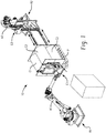
- an exemplary system 10 including a first robot R1 and a second robot R2.
- Each robot R1 and R2 includes an articulated robotic arm A1 and A2, respectively.
- Each robotic arm A1 and A2 has mounted thereon a respective end effector E1 and E2.
- Each end effector E1 and E2 is supported by its associated robotic arm A1 or A2 for movement in the X-Y-Z dimensions, as well as rotation relative to the robotic arm to which it is attached. This configuration allows virtually limitless positioning and/or orientation of the end effectors E1 and E2 with respect to the object or objects to be strapped.
- the objects to be strapped include four rolls of coiled material C1, C2, C3 and C4 (C4 not visible in FIG. 1 ), such as rolls of plastic or paper sheet material.
- the rolls C1-C4 are initially supported in a 2X2 stacked configuration on a pallet P or other support.
- Each of the rolls includes a void in the form of a central bore or opening O (see FIG. 4 ) extending therethrough, through which strapping material is to be passed to secure adjacent rolls together. That is, the present disclosure provides an automated system for positioning strapping material to form a loop extending through each central bore O of two adjacent rolls of coiled material.
- end effector E1 and E2 are positioned relative to the rolls C2 and C3 such that corresponding portions of a strapping chute extend through the central bores of each roll.
- end effector E2 includes a C-shape chute having distal end portions inserted into the central bores of the rolls C2 and C3 a sufficient distance to mate, engage with, or otherwise cooperate with a corresponding chute portion of end effector E1 such that a generally continuous chute CH (as shown in FIG. 5 ) is defined by the first and second end effectors, said chute CH extending through both central bores O of the rolls C2 and C3 and about a portion of each axial end face of each of the rolls C2 and C3.
- each end effector can be done using computer vision techniques and/or other positioning methods adapted to locate the central bore of each roll and move the end effectors into position.
- one end effector is configured to locate the central bores via a laser, and the other end effector is configured to then come into mating position with the first end effector.
- a magnetic switch or other sensing device can be provided to confirm the chute portions of the first and second end effectors E1 and E2 are in mating position to define the generally continuous chute CH.
- strapping S is deployed via end effector E1.
- the strapping S is advanced through the central bores of rolls C2 and C3 via chute CH and around the axial end faces of the same until the strapping S is returned to end effector E1.
- a tensioning mechanism is then deployed to tension the strapping to thereby draw rolls C2 and C3 together.
- the strapping is secured, such as by heat or friction welding, and trimmed as needed.
- free end is the terminal end of the strapping material that is initially advanced through the chute, while the standing portion of the strapping material is any portion of the strapping material that is not the free end.
- securing rolls C1-C4 together generally includes strapping each roll individually to at least two other rolls.
- strapping may typically be installed between rolls C1 and C2, C2 and C3, C3 and C4, and C4 and C1. Further strapping can be installed diagonally between rolls C1 and C3 and/or C2 and C4, for example.
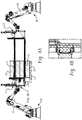
- FIG. 5 is a cross-sectional view taken through end effectors E1 and E2 illustrating the strapping chute CH formed as a generally continuous loop when end effectors E1 and E2 are positioned with their respective chute portions in abutting engagement.
- the structural members of each end effector E1/E2 forming the strapping chute CH are generally the same and will be described together.
- each end effector includes a stationary chute SC and a movable chute MC.
- a vertical chute VC connects the stationary chute SC and the movable chute MC thereby forming the general c-shape chute portion referred to above.
- Each of the stationary chute SC, movable chute MC and vertical chute VC are supported by a frame F of the end effector, which in turn is connected to a respective robot R1 or R2 (R2 not shown in FIG. 5 ).
- the stationary chute SC is fixed relative to the vertical chute VC and the movable chute MC is movable relative to the stationary chute SC along the vertical chute VC.
- the movable chute MC is movable vertically in FIG. 5 to change the vertical spacing of the movable chute MC relative to the stationary chute SC so as to change a vertical dimension of the chute CH. It will further be appreciated that both the movable chute MC and the stationary chute SC can have telescoping portions thereof for extending/retracting so as to change a horizontal dimension of the chute CH. In other embodiments, the movable and stationary chutes MC and SC are of a fixed length such that the horizontal dimension of the chute CH is fixed.
- the chute CH is formed from a plurality of opposed generally L-shape (in cross-section) chute brackets CB (See FIG. 7 ) approximately 10.16 to 20.32 centimeters (4 to 8 inches) long that are aligned end-to-end and supported along the vertical chute VC, movable MC and stationary chute SC portions of each end effector.
- Each bracket is pivotally secured and biased towards a closed position for forming the chute CH therebetween.
- the chute brackets CB can pivot away from each other to an open position to release the strap as tension is drawn on the strap. After releasing the strap, the chute brackets CB return to the closed position.
- Each movable chute MC is coupled to a servo motor SM for precise adjustment of the movable chute MC in the vertical direction, as will be described in more detail below.
- Vertical adjustment of the movable chute MC is useful for accommodating coils of material of different diameters by adjusting the vertical dimension of the chute CH.
- end effector E1 and end effector E2 operate in a master/slave arrangement.
- end effector E1 is configured to locate one or more hollow central bores or openings O in one or more coils of material, and advance the stationary chute SC and movable chute MC into the opening(s) in the coiled material until fully engaged such that a strapping head SH supported on the vertical chute VC is adjacent the coil of material.
- end effector E2 is configured to mirror the movement of end effector E1 so as to align and extend its movable chute MC and stationary chute SC into the opening(s) of the coiled material from the opposite side, and mate/abut with the stationary chute SC and movable chute MC of end effector E1.
- end effector E1/E2 occurs simultaneously, with end effector E2 essentially mirroring movement of end effector E1 as the movable and stationary chutes of each end effector are aligned and inserted in the central bore of the coiled material.
- end effector E1 may be manipulated first, with end effector E2 being manipulated after end effector E1 has first been aligned and inserted in the coiled material.
- the movable chutes MC and/or stationary chutes each include a transition block TB at a terminal end thereof that includes one or more of 1) hardware for detecting both the location of the central bore, 2) hardware for detecting when the chutes of end effector E1 are engaged/abutted with the chutes of end effector E2, and or 3) an alignment pin or other structure for ensuring accurate alignment of the components when in abutting engagement.
- FIGS. 8-13 are best seen in FIGS. 8-13 .
- a laser switch LS is provided for locating voids (e.g., the central bore O of the coiled material).
- Other sensors can be used in place of or in addition to the laser switch for sensing the central bore. Such sensors can include for example, ultrasonic sensors, cameras, electronic eyes, etc.
- Chute CH is shown as a dashed line in FIG. 8 because it is generally concealed in this view.
- a magnetic switch MS is configured to detect when the movable chutes MC of each end effector E1 and E2 are in abutting engagement. It will be appreciated that other devices for sensing engagement between the movable chutes can be provided (e.g., mechanical switches, etc.).
- the end effectors E1/E2 can be equipped to detect when the movable chutes are abuttingly engaged based on force vs. displacement analysis wherein an increase in force and/or a decrease in displacement of one or both of the end effectors generally indicates the movable chutes are abuttingly engaged.
- transition blocks TB of the stationary chutes SC are shown. Like the transition blocks TB of the movable chutes MC, the transition blocks TB can be secured to the stationary chutes SC with fasteners, such as bolts B, or the like. Although not shown, it will be appreciated that the transition blocks TB of the stationary chutes SC can also include one or more sensors as described in connection with the transition block TB of the moveable chutes MC.
- FIGS. 10-13 illustrate various views of an exemplary chute alignment pin AP for aligning respective transition blocks TB.
- Chute alignment pin AP is received in an alignment bore AB when the movable chute MC and stationary chute SC are fully engaged with respective movable chute MC and stationary chute SC of the other end effector.
- the alignment pin AP ensures precise alignment of the transition blocks TB to reduce or eliminate jamming of strapping during advancement of the strap through the chute C.
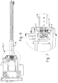
- FIGS. 14 and 15 a cross-section of end effector E1 and related components is shown.
- the strapping head SH can be any suitable strapping head.
- the exemplary strapping head SH operates to sever and bond the strap material after it is fed through the chute CH and tensioned by strap feeder/tensioner SFT.
- the strap feeder/tensioner SFT can be any suitable strap feeder/tensioner.
- the present exemplary system utilizes a strap transition component STC for guiding the strapping material S into the strapping head SH and chute CH.
- the strap transition component STC has a mounting tab MT for securing to the system, and a channel CH for guiding the strap material.
- the strap transition component STC is mounted such that the channel CH is oriented to provide a gradual transition of the approach angle of the strapping material S to the strapping head SH.
- the STC retains and controls the transition of the strap on all four sides as it approaches the main chute area.
- aspects of the present disclosure permit positioning of the end effectors E1/E2 in a wide variety of positions and orientations to enable the machine 10 to install such strapping in the configurations mentioned in the previous paragraph (as well as many other configurations) without the need to reposition the rolls C1-C4.
- the chute portions of one or both end effectors can be adjustable in length and/or lateral spacing to accommodate rolls of coiled material having various axial lengths and/or diameters.
- multiple chutes can be configured to allow simultaneously strapping of more than two rolls of material.
- the chute components can be duplicated to provide a pair of chutes CH so that pairs of rolls C1/C2 and C3/C4 can be strapped together simultaneously.
- the transverse spacing between the respective dual chutes can be adjustable to accommodate rolls of different sizes.
- Suitable strapping heads for use with aspects of the present disclosure are available commercially.
- the strapping chute components e.g., the portions of the movable chutes MC, stationary chutes SC and vertical chute VC
- the strapping chute components are also available commercially.
- the system can be used to apply strapping to products supported on a shipping pallet, and/or to secure coils of material in the coiled configuration.
- the system can further include a conveyor or other transport device for advancing products or the like into position for strapping.
- the exemplary system in accordance with the present disclosure therefore, permits application and installation of strapping to many more product types and configurations than prior art fixed-type (e.g., horizontal or vertical) strapping machines.
- the exemplary robotic strapping machine of the present disclosure has been designed to have the capability of automatically strapping products together at a variety of load types, orientations, configurations and sizes.
- the machine is adaptable to use with a wide variety of products and in a wide variety of orientations and departs from standalone machines that can only perform a limited number of functions in a limited or single orientation.
- the system of the present disclosure utilizes robotic arms to make almost unlimited motions to position a pair of strapping end effectors for strapping through voids and/or around perimeters of objects, such as coils of material, for example.
- the end effectors are specifically designed to perform these functions by having integrated motion of its strapping chutes for different widths and lengths of products/objects.
- the tooling side end effector is configured to control the feeding of the strap through the chutes, tension the strap, weld and cut the strap.
- the integrated design allows for the tensioner module and sealer module to be integrated to the tooling head end effector so that the robot can make the motions needed to complete its tasks.
- the tooling in the tooling head has been specifically designed to allow for all the automated motions to complete strapping as needed.
- the present exemplary system can be used to strap a wide variety of materials besides rolled material, which can provide added value to the system particularly in settings where both rolled and non-rolled materials are to be strapped.
Landscapes
- Engineering & Computer Science (AREA)
- Mechanical Engineering (AREA)
- Basic Packing Technique (AREA)
Claims (15)
- Système de cerclage (10) destiné à l'application de manière automatique de cerclage à au moins un objet associé, le système de cerclage (10) comprenant :un premier organe effecteur terminal (E1) et un second organe effecteur terminal (E2), chaque organe effecteur terminal (E1, E2) pouvant être monté sur un positionneur multiaxes (R1, R2) etcomportant au moins une partie d'une glissière (CH), l'organe effecteur terminal (E1, E2) étant mobile l'un par rapport à l'autre lorsqu'il est monté sur un bras robotisé de sorte que les parties de glissière de chaque organe effecteur terminal (E1, E2) peuvent être regroupées de manière sélective dans une pluralité d'orientations pour définir une boucle de glissière continue d'une façon générale à travers laquelle un matériau de cerclage peut être avancé pour entourer ledit au moins un objet associé situé au moins partiellement à l'intérieur de la boucle de glissière ;dans lequel au moins une parmi les parties de la glissière est réglable pour modifier une dimension de la glissière (CH).
- Système de cerclage (10) selon la revendication 1, dans lequel au moins un parmi les organes effecteurs terminaux (E1, E2) comprend en outre une tête de cerclage (SH) conçue pour retenir, réunir et sectionner des parties adjacentes d'un matériau de cerclage après qu'il est avancé à travers la glissière (CH).
- Système de cerclage (10) selon la revendication 1, dans lequel au moins un parmi les organes effecteurs terminaux (E1, E2) comprend en outre un dispositif de distribution/tensionnement du cerclage (SFT),
le dispositif de distribution/tensionnement du cerclage (SFT) conçu pour avancer le matériau de cerclage à travers la glissière (CH), et pour appliquer une tension sur le matériau de cerclage après l'avancement du matériau de cerclage à travers la glissière (CH) de manière à tirer le matériau de cerclage contre ledit au moins un objet associé avant que la tête de cerclage (SH) ne réunisse et ne sectionne le matériau de cerclage. - Machine de cerclage selon la revendication 1, dans laquelle au moins une parmi les parties de glissière est en forme de C, grâce à quoi lorsque les parties de glissière sont regroupées, la glissière (CH) est une glissière rectangulaire.
- Machine de cerclage selon la revendication 4, dans laquelle ladite au moins une partie de glissière en forme de C (CH) est constituée d'une partie glissière verticale (VC), d'une glissière fixe (CH) fixée à la partie de glissière verticale (VC) et s'étendant à angle droit et d'une partie mobile de la partie de glissière (MC) raccordée de manière mobile à la partie verticale de la partie de glissière (VC) et s'étendant à angle droit de celui-ci.
- Machine de cerclage selon la revendication 1, comprenant en outre un capteur (LS) monté sur au moins une parmi les parties de glissière destinées à détecter un vide dans ledit au moins un objet associé.
- Machine de cerclage selon la revendication 1, comprenant en outre un capteur (MS) destiné à détecter lorsque les parties de glissière sont entrées en prise de manière à venir en butée.
- Machine de cerclage selon la revendication 1, dans laquelle les parties de glissière comportent des supports de glissière pouvant pivoter (CB) adaptés à se déplacer entre une position fermée destinée à la rétention d'un matériau de cerclage pendant la distribution du matériau de cerclage à travers la glissière (CH) et une position ouverte destinée à relâcher le matériau de cerclage lorsque la tension est appliquée sur le matériau de cerclage.
- Machine de cerclage selon la revendication 1, dans laquelle les parties de glissière de chaque organe effecteur terminal (E1, E2) comportent une partie saillante ou un renfoncement (AP, AB) destiné à l'accouplement avec un renfoncement ou une partie saillante correspondant (AP, AB) sur l'autre lorsque les parties de glissière sont regroupées, grâce à quoi les parties saillantes/renfoncements alignent les partie de glissière de chaque organe effecteur terminal (E1, E2) lors de l'entrée en prise en butée l'une avec l'autre.
- Machine de cerclage selon la revendication 1, comprenant en outre les positionneurs multiaxes (R1, R2), dans laquelle l'organe le premier et le second organe effecteur terminal (E1, E2) montés sur un positionneur multiaxes respectif (R1, R2), dans laquelle l'organe effecteur terminal (E1, E2) est mobile dans au moins six axes et dans laquelle les positionneurs multiaxes (R1, R2) sont des bras robotisés.
- Procédé d'installation de manière automatique du matériau de cerclage sur un objet associé présentant un vide, le procédé comprenant :le positionnement d'une première partie de glissière à l'intérieur du vide ;l'assemblage de la première partie de glissière à une seconde partie de glissière pour former une glissière continue (CH) ;l'avancement d'un matériau de cerclage (S) à travers la glissière continue (CH) pour former une boucle de matériau de cerclage ;l'assemblage d'une extrémité libre du matériau de cerclage à la partie immobile du matériau de cerclage pour former ainsi une boucle immobilisée du matériau de cerclage passant à travers le vide dans lequel au moins une parmi la première partie de glissière et/ou la seconde partie de glissière fait partie d'un organe effecteur terminal (E1, E2) monté sur un bras robotisé.
- Procédé selon la revendication 11, dans lequel la première partie de glissière fait partie d'un premier organe effecteur terminal (E1, E2) monté sur un premier positionneur multiaxes (R1, R2) et la seconde partie de glissière fait partie d'un second organe effecteur terminal (E1, E2) monté sur un second positionneur multiaxes (R1, R2), dans lequel le positionnement de la première partie de glissière comprend la localisation du vide dans l'objet associé à l'aide d'un capteur monté sur le premier organe effecteur terminal (E1, E2) et l'avancement de la première partie de glissière au moins partiellement dans le vide, dans lequel l'assemblage de la première partie de glissière à la seconde partie de glissière comprend l'avancement de la seconde partie de glissière au moins partiellement dans le vide dans l'objet associé d'un côté opposé à la première partie de glissière de sorte que les première et seconde parties de glissière soient réunies à l'intérieur du vide de l'objet associé.
- Procédé selon la revendication 12, dans lequel les première et seconde parties de glissière sont simultanément groupées en entrée en prise en butée à l'intérieur du vide.
- Procédé selon la revendication 13, dans lequel le premier bras robotisé et le second bras robotisé sont commandés dans une configuration maître/esclave avec le second déplacement en miroir de bras robotisé du premier bras robotisé.
- Procédé selon la revendication 14, comprenant en outre le tensionnement du matériau de cerclage (6) avant d'assembler l'extrémité libre du matériau de cerclage (S) à la partie immobile du matériau de cerclage.
Applications Claiming Priority (2)
| Application Number | Priority Date | Filing Date | Title |
|---|---|---|---|
| US201662358368P | 2016-07-05 | 2016-07-05 | |
| PCT/US2017/035895 WO2018009292A1 (fr) | 2016-07-05 | 2017-06-05 | Machine et procédé de cerclage robotisé |
Publications (2)
| Publication Number | Publication Date |
|---|---|
| EP3481729A1 EP3481729A1 (fr) | 2019-05-15 |
| EP3481729B1 true EP3481729B1 (fr) | 2021-04-14 |
Family
ID=59153283
Family Applications (1)
| Application Number | Title | Priority Date | Filing Date |
|---|---|---|---|
| EP17732651.9A Active EP3481729B1 (fr) | 2016-07-05 | 2017-06-05 | Machine de cerclage robotise et procede |
Country Status (3)
| Country | Link |
|---|---|
| US (2) | US11142359B2 (fr) |
| EP (1) | EP3481729B1 (fr) |
| WO (1) | WO2018009292A1 (fr) |
Families Citing this family (7)
| Publication number | Priority date | Publication date | Assignee | Title |
|---|---|---|---|---|
| SE545823C2 (en) * | 2020-04-30 | 2024-02-13 | Lamiflex Group Ab | Robot Tool, Robot System and Method for Coil Packaging |
| SE547304C2 (en) * | 2020-12-23 | 2025-06-24 | Lamiflex Group Ab | Robot System and Method for Coil Packaging |
| US20230391481A1 (en) * | 2022-06-01 | 2023-12-07 | Taylor-Winfield Technologies, Inc. | Robotic strapping machine with pivoting strapping head and method |
| US12371214B2 (en) * | 2023-05-08 | 2025-07-29 | Lamiflex Group Ab | Edge protection mounting device in a system for sheet coil packaging |
| US12371209B2 (en) * | 2023-05-08 | 2025-07-29 | Lamiflex Group Ab | Edge protection mounting in a system for sheet coil packaging |
| US12312109B2 (en) * | 2023-06-02 | 2025-05-27 | Slab Innovation Inc. | Adaptable spacer roping installation system for casted concrete products or the likes and palletizing system therewith |
| US12371208B2 (en) * | 2023-10-05 | 2025-07-29 | Lamiflex Group Ab | Sheet coil packaging with end attachment |
Family Cites Families (16)
| Publication number | Priority date | Publication date | Assignee | Title |
|---|---|---|---|---|
| FR2057524A5 (fr) | 1969-08-25 | 1971-05-21 | Ural Z Tyazhelogo | |
| US4829753A (en) * | 1988-01-15 | 1989-05-16 | Bricmont Francis H | Apparatus for wrapping overlapping laps of strip material over a cylindrical object having an axial opening therein |
| US4951562A (en) * | 1989-03-16 | 1990-08-28 | Signode Corporation | Strapping machine for compressible loads |
| US5282347A (en) * | 1991-11-12 | 1994-02-01 | John Lysaght (Australia) Limited | Wrapping apparatus |
| US5400706A (en) | 1993-09-21 | 1995-03-28 | Signode Corporation | Machine for strapping load-carrying skid |
| US5540142A (en) | 1993-12-17 | 1996-07-30 | Signode Corporation | Machine for strapping sheet metal coil |
| FI105666B (fi) * | 1998-02-11 | 2000-09-29 | Haloila M Oy Ab | Käärintälaite |
| JP3774626B2 (ja) * | 1999-01-29 | 2006-05-17 | 鋼鈑工業株式会社 | 包装装置 |
| FI20060457A0 (fi) | 2006-05-10 | 2006-05-10 | Juha-Matti Laensikallio | Käärintälaite |
| US8037661B2 (en) * | 2007-01-12 | 2011-10-18 | Illinois Tool Works Inc. | Shuttle change system and method for wrapping apparatus |
| US7526995B2 (en) * | 2007-02-28 | 2009-05-05 | H.W.J. Designs For Agribusiness, Inc. | Strap welding system and method |
| US8051770B2 (en) | 2008-06-11 | 2011-11-08 | Posco M-Tech | Robot binding apparatus for coil packaging |
| US8042460B2 (en) * | 2008-06-11 | 2011-10-25 | Posco M-Tech | Head unit for coil packaging |
| US7861649B2 (en) * | 2008-12-19 | 2011-01-04 | Illinois Tool Works Inc. | Self-adjusting stripper pin for strapping machine strap chute |
| US8020488B1 (en) * | 2010-03-08 | 2011-09-20 | Tekpak Corporation | Strapping machine |
| NL2012215C2 (nl) | 2014-02-06 | 2015-08-10 | Bandall Benelux B V | Inrichting voor het rond een product aanbrengen van een band flexibel materiaal. |
-
2017
- 2017-06-05 US US16/306,923 patent/US11142359B2/en active Active - Reinstated
- 2017-06-05 WO PCT/US2017/035895 patent/WO2018009292A1/fr not_active Ceased
- 2017-06-05 EP EP17732651.9A patent/EP3481729B1/fr active Active
-
2021
- 2021-09-08 US US17/468,807 patent/US11987407B2/en active Active
Non-Patent Citations (1)
| Title |
|---|
| None * |
Also Published As
| Publication number | Publication date |
|---|---|
| US11987407B2 (en) | 2024-05-21 |
| US20220089305A1 (en) | 2022-03-24 |
| EP3481729A1 (fr) | 2019-05-15 |
| WO2018009292A1 (fr) | 2018-01-11 |
| US11142359B2 (en) | 2021-10-12 |
| US20190291901A1 (en) | 2019-09-26 |
Similar Documents
| Publication | Publication Date | Title |
|---|---|---|
| US11987407B2 (en) | Robotic strapping machine and method | |
| CN101180152B (zh) | 用于制作所需长度的带材的设备以及制作该带材的方法 | |
| CN110883414B (zh) | 带有用于高速生产焊接的浮动式焊接器的系统和方法 | |
| US6907711B2 (en) | Sheet package producing system, sheet handling device, and fillet folding device | |
| TW201304888A (zh) | 進給緊固件之方法及裝置 | |
| US20100024188A1 (en) | Strap Removal System | |
| WO2015136732A1 (fr) | Dispositif et procédé de coupe | |
| EP1857219B1 (fr) | Systèmes et procédés de positionnement structurel montés sur tête d'outil | |
| US20080229712A1 (en) | Self-Aligning Former Assembly | |
| MX2014011664A (es) | Metodo para hacer un borde de alambre y aparato para poner en practica el metodo. | |
| WO2015136715A1 (fr) | Dispositif de coupe | |
| CA2059050C (fr) | Dispositif d'actionnement du systeme d'attache pour un chassis de fixation monte sur convoyeur | |
| CN117157167A (zh) | 用于将多个坯件焊接成部件的系统 | |
| US20230391481A1 (en) | Robotic strapping machine with pivoting strapping head and method | |
| EP0615317A2 (fr) | Dispositif de guidage de câble électrique | |
| US4701238A (en) | Wrapping machine | |
| EP0648443B1 (fr) | Appareil d'inspection d'état d'accouplement des butées d'extrémité des fermetures à glissière et machine pour fixer des butées d'extrémité équipée d'un tel appareil | |
| WO2017183119A1 (fr) | Dispositif de fabrication de fermeture à glissière et procédé de fabrication de fermeture à glissière | |
| JP2019029337A (ja) | 電線溶着装置 | |
| KR101148073B1 (ko) | 이송장치 및 이를 구비한 용접장치 | |
| EP0753911B1 (fr) | Dispositif de guidage et de coupage de fils | |
| EP3167969B1 (fr) | Machine pour traiter des barres en aluminium, alliages légers, pvc ou analogues | |
| JPWO2018134912A1 (ja) | 部品挿入機 | |
| US12378091B2 (en) | Application device having a helix feed, robot device and production system | |
| JPH0732499Y2 (ja) | 部品分離供給装置 |
Legal Events
| Date | Code | Title | Description |
|---|---|---|---|
| STAA | Information on the status of an ep patent application or granted ep patent |
Free format text: STATUS: UNKNOWN |
|
| STAA | Information on the status of an ep patent application or granted ep patent |
Free format text: STATUS: THE INTERNATIONAL PUBLICATION HAS BEEN MADE |
|
| PUAI | Public reference made under article 153(3) epc to a published international application that has entered the european phase |
Free format text: ORIGINAL CODE: 0009012 |
|
| STAA | Information on the status of an ep patent application or granted ep patent |
Free format text: STATUS: REQUEST FOR EXAMINATION WAS MADE |
|
| 17P | Request for examination filed |
Effective date: 20190107 |
|
| AK | Designated contracting states |
Kind code of ref document: A1 Designated state(s): AL AT BE BG CH CY CZ DE DK EE ES FI FR GB GR HR HU IE IS IT LI LT LU LV MC MK MT NL NO PL PT RO RS SE SI SK SM TR |
|
| AX | Request for extension of the european patent |
Extension state: BA ME |
|
| DAV | Request for validation of the european patent (deleted) | ||
| DAX | Request for extension of the european patent (deleted) | ||
| STAA | Information on the status of an ep patent application or granted ep patent |
Free format text: STATUS: EXAMINATION IS IN PROGRESS |
|
| 17Q | First examination report despatched |
Effective date: 20200306 |
|
| GRAP | Despatch of communication of intention to grant a patent |
Free format text: ORIGINAL CODE: EPIDOSNIGR1 |
|
| STAA | Information on the status of an ep patent application or granted ep patent |
Free format text: STATUS: GRANT OF PATENT IS INTENDED |
|
| INTG | Intention to grant announced |
Effective date: 20201123 |
|
| GRAS | Grant fee paid |
Free format text: ORIGINAL CODE: EPIDOSNIGR3 |
|
| GRAA | (expected) grant |
Free format text: ORIGINAL CODE: 0009210 |
|
| STAA | Information on the status of an ep patent application or granted ep patent |
Free format text: STATUS: THE PATENT HAS BEEN GRANTED |
|
| AK | Designated contracting states |
Kind code of ref document: B1 Designated state(s): AL AT BE BG CH CY CZ DE DK EE ES FI FR GB GR HR HU IE IS IT LI LT LU LV MC MK MT NL NO PL PT RO RS SE SI SK SM TR |
|
| REG | Reference to a national code |
Ref country code: GB Ref legal event code: FG4D |
|
| REG | Reference to a national code |
Ref country code: CH Ref legal event code: EP |
|
| REG | Reference to a national code |
Ref country code: DE Ref legal event code: R096 Ref document number: 602017036668 Country of ref document: DE |
|
| REG | Reference to a national code |
Ref country code: IE Ref legal event code: FG4D |
|
| REG | Reference to a national code |
Ref country code: AT Ref legal event code: REF Ref document number: 1382170 Country of ref document: AT Kind code of ref document: T Effective date: 20210515 |
|
| REG | Reference to a national code |
Ref country code: SE Ref legal event code: TRGR |
|
| REG | Reference to a national code |
Ref country code: LT Ref legal event code: MG9D |
|
| REG | Reference to a national code |
Ref country code: AT Ref legal event code: MK05 Ref document number: 1382170 Country of ref document: AT Kind code of ref document: T Effective date: 20210414 |
|
| REG | Reference to a national code |
Ref country code: NL Ref legal event code: MP Effective date: 20210414 |
|
| PG25 | Lapsed in a contracting state [announced via postgrant information from national office to epo] |
Ref country code: FI Free format text: LAPSE BECAUSE OF FAILURE TO SUBMIT A TRANSLATION OF THE DESCRIPTION OR TO PAY THE FEE WITHIN THE PRESCRIBED TIME-LIMIT Effective date: 20210414 Ref country code: LT Free format text: LAPSE BECAUSE OF FAILURE TO SUBMIT A TRANSLATION OF THE DESCRIPTION OR TO PAY THE FEE WITHIN THE PRESCRIBED TIME-LIMIT Effective date: 20210414 Ref country code: NL Free format text: LAPSE BECAUSE OF FAILURE TO SUBMIT A TRANSLATION OF THE DESCRIPTION OR TO PAY THE FEE WITHIN THE PRESCRIBED TIME-LIMIT Effective date: 20210414 Ref country code: HR Free format text: LAPSE BECAUSE OF FAILURE TO SUBMIT A TRANSLATION OF THE DESCRIPTION OR TO PAY THE FEE WITHIN THE PRESCRIBED TIME-LIMIT Effective date: 20210414 Ref country code: BG Free format text: LAPSE BECAUSE OF FAILURE TO SUBMIT A TRANSLATION OF THE DESCRIPTION OR TO PAY THE FEE WITHIN THE PRESCRIBED TIME-LIMIT Effective date: 20210714 Ref country code: AT Free format text: LAPSE BECAUSE OF FAILURE TO SUBMIT A TRANSLATION OF THE DESCRIPTION OR TO PAY THE FEE WITHIN THE PRESCRIBED TIME-LIMIT Effective date: 20210414 |
|
| PG25 | Lapsed in a contracting state [announced via postgrant information from national office to epo] |
Ref country code: GR Free format text: LAPSE BECAUSE OF FAILURE TO SUBMIT A TRANSLATION OF THE DESCRIPTION OR TO PAY THE FEE WITHIN THE PRESCRIBED TIME-LIMIT Effective date: 20210715 Ref country code: LV Free format text: LAPSE BECAUSE OF FAILURE TO SUBMIT A TRANSLATION OF THE DESCRIPTION OR TO PAY THE FEE WITHIN THE PRESCRIBED TIME-LIMIT Effective date: 20210414 Ref country code: IS Free format text: LAPSE BECAUSE OF FAILURE TO SUBMIT A TRANSLATION OF THE DESCRIPTION OR TO PAY THE FEE WITHIN THE PRESCRIBED TIME-LIMIT Effective date: 20210814 Ref country code: PL Free format text: LAPSE BECAUSE OF FAILURE TO SUBMIT A TRANSLATION OF THE DESCRIPTION OR TO PAY THE FEE WITHIN THE PRESCRIBED TIME-LIMIT Effective date: 20210414 Ref country code: NO Free format text: LAPSE BECAUSE OF FAILURE TO SUBMIT A TRANSLATION OF THE DESCRIPTION OR TO PAY THE FEE WITHIN THE PRESCRIBED TIME-LIMIT Effective date: 20210714 Ref country code: PT Free format text: LAPSE BECAUSE OF FAILURE TO SUBMIT A TRANSLATION OF THE DESCRIPTION OR TO PAY THE FEE WITHIN THE PRESCRIBED TIME-LIMIT Effective date: 20210816 Ref country code: RS Free format text: LAPSE BECAUSE OF FAILURE TO SUBMIT A TRANSLATION OF THE DESCRIPTION OR TO PAY THE FEE WITHIN THE PRESCRIBED TIME-LIMIT Effective date: 20210414 |
|
| REG | Reference to a national code |
Ref country code: DE Ref legal event code: R097 Ref document number: 602017036668 Country of ref document: DE |
|
| PG25 | Lapsed in a contracting state [announced via postgrant information from national office to epo] |
Ref country code: MC Free format text: LAPSE BECAUSE OF FAILURE TO SUBMIT A TRANSLATION OF THE DESCRIPTION OR TO PAY THE FEE WITHIN THE PRESCRIBED TIME-LIMIT Effective date: 20210414 Ref country code: DK Free format text: LAPSE BECAUSE OF FAILURE TO SUBMIT A TRANSLATION OF THE DESCRIPTION OR TO PAY THE FEE WITHIN THE PRESCRIBED TIME-LIMIT Effective date: 20210414 Ref country code: EE Free format text: LAPSE BECAUSE OF FAILURE TO SUBMIT A TRANSLATION OF THE DESCRIPTION OR TO PAY THE FEE WITHIN THE PRESCRIBED TIME-LIMIT Effective date: 20210414 Ref country code: CZ Free format text: LAPSE BECAUSE OF FAILURE TO SUBMIT A TRANSLATION OF THE DESCRIPTION OR TO PAY THE FEE WITHIN THE PRESCRIBED TIME-LIMIT Effective date: 20210414 Ref country code: ES Free format text: LAPSE BECAUSE OF FAILURE TO SUBMIT A TRANSLATION OF THE DESCRIPTION OR TO PAY THE FEE WITHIN THE PRESCRIBED TIME-LIMIT Effective date: 20210414 Ref country code: RO Free format text: LAPSE BECAUSE OF FAILURE TO SUBMIT A TRANSLATION OF THE DESCRIPTION OR TO PAY THE FEE WITHIN THE PRESCRIBED TIME-LIMIT Effective date: 20210414 Ref country code: SM Free format text: LAPSE BECAUSE OF FAILURE TO SUBMIT A TRANSLATION OF THE DESCRIPTION OR TO PAY THE FEE WITHIN THE PRESCRIBED TIME-LIMIT Effective date: 20210414 Ref country code: SK Free format text: LAPSE BECAUSE OF FAILURE TO SUBMIT A TRANSLATION OF THE DESCRIPTION OR TO PAY THE FEE WITHIN THE PRESCRIBED TIME-LIMIT Effective date: 20210414 |
|
| REG | Reference to a national code |
Ref country code: CH Ref legal event code: PL |
|
| PLBE | No opposition filed within time limit |
Free format text: ORIGINAL CODE: 0009261 |
|
| STAA | Information on the status of an ep patent application or granted ep patent |
Free format text: STATUS: NO OPPOSITION FILED WITHIN TIME LIMIT |
|
| REG | Reference to a national code |
Ref country code: BE Ref legal event code: MM Effective date: 20210630 |
|
| 26N | No opposition filed |
Effective date: 20220117 |
|
| PG25 | Lapsed in a contracting state [announced via postgrant information from national office to epo] |
Ref country code: LU Free format text: LAPSE BECAUSE OF NON-PAYMENT OF DUE FEES Effective date: 20210605 |
|
| PG25 | Lapsed in a contracting state [announced via postgrant information from national office to epo] |
Ref country code: LI Free format text: LAPSE BECAUSE OF NON-PAYMENT OF DUE FEES Effective date: 20210630 Ref country code: IE Free format text: LAPSE BECAUSE OF NON-PAYMENT OF DUE FEES Effective date: 20210605 Ref country code: CH Free format text: LAPSE BECAUSE OF NON-PAYMENT OF DUE FEES Effective date: 20210630 |
|
| PG25 | Lapsed in a contracting state [announced via postgrant information from national office to epo] |
Ref country code: IS Free format text: LAPSE BECAUSE OF FAILURE TO SUBMIT A TRANSLATION OF THE DESCRIPTION OR TO PAY THE FEE WITHIN THE PRESCRIBED TIME-LIMIT Effective date: 20210814 Ref country code: AL Free format text: LAPSE BECAUSE OF FAILURE TO SUBMIT A TRANSLATION OF THE DESCRIPTION OR TO PAY THE FEE WITHIN THE PRESCRIBED TIME-LIMIT Effective date: 20210414 |
|
| PG25 | Lapsed in a contracting state [announced via postgrant information from national office to epo] |
Ref country code: IT Free format text: LAPSE BECAUSE OF FAILURE TO SUBMIT A TRANSLATION OF THE DESCRIPTION OR TO PAY THE FEE WITHIN THE PRESCRIBED TIME-LIMIT Effective date: 20210414 Ref country code: BE Free format text: LAPSE BECAUSE OF NON-PAYMENT OF DUE FEES Effective date: 20210630 |
|
| PG25 | Lapsed in a contracting state [announced via postgrant information from national office to epo] |
Ref country code: CY Free format text: LAPSE BECAUSE OF FAILURE TO SUBMIT A TRANSLATION OF THE DESCRIPTION OR TO PAY THE FEE WITHIN THE PRESCRIBED TIME-LIMIT Effective date: 20210414 |
|
| PG25 | Lapsed in a contracting state [announced via postgrant information from national office to epo] |
Ref country code: HU Free format text: LAPSE BECAUSE OF FAILURE TO SUBMIT A TRANSLATION OF THE DESCRIPTION OR TO PAY THE FEE WITHIN THE PRESCRIBED TIME-LIMIT; INVALID AB INITIO Effective date: 20170605 |
|
| PG25 | Lapsed in a contracting state [announced via postgrant information from national office to epo] |
Ref country code: MK Free format text: LAPSE BECAUSE OF FAILURE TO SUBMIT A TRANSLATION OF THE DESCRIPTION OR TO PAY THE FEE WITHIN THE PRESCRIBED TIME-LIMIT Effective date: 20210414 |
|
| PG25 | Lapsed in a contracting state [announced via postgrant information from national office to epo] |
Ref country code: MT Free format text: LAPSE BECAUSE OF FAILURE TO SUBMIT A TRANSLATION OF THE DESCRIPTION OR TO PAY THE FEE WITHIN THE PRESCRIBED TIME-LIMIT Effective date: 20210414 |
|
| PGFP | Annual fee paid to national office [announced via postgrant information from national office to epo] |
Ref country code: DE Payment date: 20250509 Year of fee payment: 9 |
|
| PGFP | Annual fee paid to national office [announced via postgrant information from national office to epo] |
Ref country code: GB Payment date: 20250508 Year of fee payment: 9 |
|
| PGFP | Annual fee paid to national office [announced via postgrant information from national office to epo] |
Ref country code: FR Payment date: 20250512 Year of fee payment: 9 |
|
| PGFP | Annual fee paid to national office [announced via postgrant information from national office to epo] |
Ref country code: SE Payment date: 20250609 Year of fee payment: 9 |
|
| PG25 | Lapsed in a contracting state [announced via postgrant information from national office to epo] |
Ref country code: TR Free format text: LAPSE BECAUSE OF FAILURE TO SUBMIT A TRANSLATION OF THE DESCRIPTION OR TO PAY THE FEE WITHIN THE PRESCRIBED TIME-LIMIT Effective date: 20210414 |