EP3481763B1 - Élément de préhension de goulot comportant un verrouillage - Google Patents
Élément de préhension de goulot comportant un verrouillage Download PDFInfo
- Publication number
- EP3481763B1 EP3481763B1 EP17828245.5A EP17828245A EP3481763B1 EP 3481763 B1 EP3481763 B1 EP 3481763B1 EP 17828245 A EP17828245 A EP 17828245A EP 3481763 B1 EP3481763 B1 EP 3481763B1
- Authority
- EP
- European Patent Office
- Prior art keywords
- central shaft
- gripper
- gripper assembly
- cam follower
- cam
- Prior art date
- Legal status (The legal status is an assumption and is not a legal conclusion. Google has not performed a legal analysis and makes no representation as to the accuracy of the status listed.)
- Active
Links
Images





Classifications
-
- B—PERFORMING OPERATIONS; TRANSPORTING
- B67—OPENING, CLOSING OR CLEANING BOTTLES, JARS OR SIMILAR CONTAINERS; LIQUID HANDLING
- B67C—CLEANING, FILLING WITH LIQUIDS OR SEMILIQUIDS, OR EMPTYING, OF BOTTLES, JARS, CANS, CASKS, BARRELS, OR SIMILAR CONTAINERS, NOT OTHERWISE PROVIDED FOR; FUNNELS
- B67C3/00—Bottling liquids or semiliquids; Filling jars or cans with liquids or semiliquids using bottling or like apparatus; Filling casks or barrels with liquids or semiliquids
- B67C3/02—Bottling liquids or semiliquids; Filling jars or cans with liquids or semiliquids using bottling or like apparatus
- B67C3/22—Details
- B67C3/24—Devices for supporting or handling bottles
- B67C3/242—Devices for supporting or handling bottles engaging with bottle necks
-
- B—PERFORMING OPERATIONS; TRANSPORTING
- B25—HAND TOOLS; PORTABLE POWER-DRIVEN TOOLS; MANIPULATORS
- B25J—MANIPULATORS; CHAMBERS PROVIDED WITH MANIPULATION DEVICES
- B25J15/00—Gripping heads and other end effectors
- B25J15/0033—Gripping heads and other end effectors with gripping surfaces having special shapes
- B25J15/0038—Cylindrical gripping surfaces
-
- B—PERFORMING OPERATIONS; TRANSPORTING
- B25—HAND TOOLS; PORTABLE POWER-DRIVEN TOOLS; MANIPULATORS
- B25J—MANIPULATORS; CHAMBERS PROVIDED WITH MANIPULATION DEVICES
- B25J15/00—Gripping heads and other end effectors
- B25J15/02—Gripping heads and other end effectors servo-actuated
- B25J15/0253—Gripping heads and other end effectors servo-actuated comprising parallel grippers
- B25J15/028—Gripping heads and other end effectors servo-actuated comprising parallel grippers actuated by cams
-
- B—PERFORMING OPERATIONS; TRANSPORTING
- B65—CONVEYING; PACKING; STORING; HANDLING THIN OR FILAMENTARY MATERIAL
- B65G—TRANSPORT OR STORAGE DEVICES, e.g. CONVEYORS FOR LOADING OR TIPPING, SHOP CONVEYOR SYSTEMS OR PNEUMATIC TUBE CONVEYORS
- B65G47/00—Article or material-handling devices associated with conveyors; Methods employing such devices
- B65G47/74—Feeding, transfer, or discharging devices of particular kinds or types
- B65G47/90—Devices for picking-up and depositing articles or materials
- B65G47/904—Devices for picking-up and depositing articles or materials provided with rotary movements only
-
- B—PERFORMING OPERATIONS; TRANSPORTING
- B65—CONVEYING; PACKING; STORING; HANDLING THIN OR FILAMENTARY MATERIAL
- B65G—TRANSPORT OR STORAGE DEVICES, e.g. CONVEYORS FOR LOADING OR TIPPING, SHOP CONVEYOR SYSTEMS OR PNEUMATIC TUBE CONVEYORS
- B65G2201/00—Indexing codes relating to handling devices, e.g. conveyors, characterised by the type of product or load being conveyed or handled
- B65G2201/02—Articles
- B65G2201/0235—Containers
- B65G2201/0244—Bottles
- B65G2201/0247—Suspended bottles
Definitions
- the present disclosure relates to a gripper assembly for gripping and locking a portion of a container, such as a bottle neck.
- packages such as bottles
- the bottles may be washed, rinsed, sterilized, shaped, and/or printed on before the bottles are filled with a product.
- the bottles may be manipulated by a bottle conveyor or handling device.
- the bottle conveyor or handling device may adjust a position and/or orientation of the bottle and/or transport the bottle to various stations within a packaging facility.
- the various stations may include a washing station, a rinsing station, a sterilization station, a shaping station, a printing station, and/or other suitable stations.
- a bottle conveyor or handling device includes a gripper assembly.
- the gripper assembly may be configured to grip a portion of a bottle, such as a bottle neck.
- the gripper assembly may include grippers configured to grip a bottle neck.
- the grippers may include a set of jaws that may be selectively moveable between an opened and a closed position.
- the jaws may be controlled and/or moved by various suitable means.
- the jaws may be electrically or pneumatically controlled. Electrical and/or pneumatic control systems may require various electrical and/or pneumatic components to be disposed on, coupled to, and/or attached to the bottle conveyor or handling device.
- the electrical and/or pneumatic components may limit a range of motion of the bottle conveyor or handling device and/or get in the way of various components of the bottle conveyor or handling device and/or various components of the packing facility. Accordingly, a gripper assembly configured to mechanically control grippers may be desirable.
- PCT publication WO 2011/121 007 A1 discloses a gripper assembly according to the preamble of claim 1.
- Said publication discloses a device for transporting a tubular preform, wherein the device comprises a gripper for gripping the preform externally by its neck, wherein the gripper is mounted to rotate around a vertical axis of rotation on a plate so as to cause the preform gripped to rotate around its main axis, wherein the device further comprises a first jaw and a second jaw opposite the gripper, each of which is intended to cooperate with an angular sector of the external face of the neck of the preform, at least one of the two jaws being movable in a direction generally orthogonal to the axis of rotation of the gripper.
- the invention provides a gripper assembly according to claim 1.
- Said gripper assembly for gripping a portion of a container includes a central shaft, a spindle configured to rotate about a vertical axis, and a first cam follower.
- the assembly also includes an actuating plate disposed on or about the spindle. The actuating plate is configured to actuate toward the central shaft in response to a force applied to the first cam follower.
- the assembly also includes a gripper configured to grip a portion of a container and including a pair of jaws. The gripper is configured to at least one of open and close in response to the actuating plate being actuated toward the central shaft. Further, the assembly includes a locking cam configured to contact the first cam follower and in at least one position to limit movement of the actuating plate toward the central shaft.
- containers such as bottles
- the containers and/or bottles may be manipulated and/or positioned by a bottle conveyor or handling device.
- the bottle conveyor or handling device may adjust a position of the container and/or bottle and/or transport the container and/or bottle to various stations.
- the various stations may include a bottle loading station, a bottle unloading station, a washing station, a rinsing station, a sterilization station, a shaping station, a printing station, and/or other suitable stations.
- the bottle conveyor or handling device may include a gripping assembly configured to grip at least a portion of the container and/or bottle while the bottle conveyor or handling device conveys the gripper assembly through the packaging facility.
- the assembly 10 may include a first or lower portion 12 and a second or upper portion 14.
- the first portion 12 may include the spindle 16 of the gripper assembly 10.
- the spindle 16 may include a first face 18 and a second face 20.
- the spindle 16 is configured to rotate about a vertical axis and may rotate about the central shaft 22, as generally illustrated in FIG. 2 .
- the assembly 10 includes one or more grippers 24.
- a gripper 24 may include an attachment end 26.
- the attachment end 26 may be attached and/or connected to a portion of a bracket 28.
- the bracket 28 may be attached and/or connected to the second face 20 of the spindle 16.
- the bracket 28 may be configured to rotate substantially in tandem with the spindle 16.
- the gripper element 24 includes a first jaw 30 and a second jaw 32.
- the first jaw 30 may be attached and/or connected to a portion of a bracket 28.
- the first jaw 30 may be attached and/or connected to a portion of the bracket 28, for example, via one or more fasteners.
- the second jaw 32 may be attached and/or connected to a portion of the bracket 28.
- the second jaw 32 may be attached and/or connected to a portion of the bracket 28, for example, via one or more fasteners.
- the fasteners may comprise, but are not limited to, socket head cap screws, screws, pins, dowel pins, rivets, weld joints, and/or other suitable fasteners.
- the gripper 24 includes a receiving portion 34.
- the receiving portion 34 may be disposed at an end of the gripper 24 that is opposite the attachment end 26.
- the receiving portion 34 includes an opening 36.
- the opening 36 is configured to receive a portion of a container and/or bottle.
- the opening 36 may be configured to receive a portion of a bottle neck.
- the receiving portion 34 may include a plurality of retainers 38.
- the retainers 38 may be disposed on one or more of a first jaw 30 and a second jaw 32.
- the retainers 38 may comprise a one or more recesses and/or protrusions.
- the retainers 38 may include a plurality of threads configured to operationally or functionally mate with a plurality of threads associated with a bottle neck. In this manner, a bottle neck may fit securely and/or snuggly within the opening 36.
- the gripper 24 may be an interchangeable component of the assembly 10.
- the gripper 24 may be detached and/or removed from the bracket 28.
- Another gripper which may be a substitute gripper, may then be attached and/or connected to the bracket 28.
- the substitute gripper may include a plurality of recesses and/or protrusions configured to receive and/or mate with a portion of a container and/or bottle.
- the substitute gripper may be configured to operationally or functionally mate with a different size and/or configured bottle neck than the gripper 24. That is, by permitting use of various grippers, the assembly 10 may be configured to grip containers and/or bottles having various shapes, sizes, and/or characteristics.
- the assembly 10 may include one or more standoffs 40.
- the one or more standoffs 40 may extend away from a portion of a bearing plate 42.
- the one or more standoffs 40 may be configured to attach and/or connect the assembly 10 to a container and/or bottle conveyance system.
- the bearing plate 42 may be configured to support and/or connect the assembly 10 when the assembly 10 is attached and/or connected to a conveyance or handling system.
- the one or more standoffs 40 may be received by and/or connected to a bottle conveyor or handling device.
- the bottle processing line may include various bottle processing stations.
- the bottle processing stations may include a bottle loading station, a bottle unloading station, a rinse station, a printing station, and/or other suitable processing stations.
- the assembly 10 may be conveyed through a bottle processing line when the assembly 10 is received by and/or connected to the bottle conveyor or handling device.
- the bearing plate 42 may include a number plate 44.
- the number plate 44 may include an identifier associated with the assembly 10.
- the identifier may include a serial number, station number, or other suitable identifiers.
- a central shaft 22 may pass through an aperture disposed in the bearing plate 42.
- the central shaft 22 may extend vertically between the first portion 12 and the second portion 14.
- a first end of the central shaft 22 may be attached and/or connected to the spindle 16.
- the first end of the central shaft 22 may be disposed at or near the second face 20 of the spindle 16.
- the assembly 10 may include an encoder 46.
- the encoder 46 may include an encoder ring mount 48 and an encoder ring 50.
- An encoder ring mount 48 may be configured to support an encoder ring 50.
- an encoder ring 50 may be attached and/or connected to the encoder ring mount 48 via one or more fasteners.
- the fasteners may include, but are not limited to, socket head cap screws, screws, pins, dowel pins, rivets, weld joints, and/or other suitable fasteners.
- the encoder ring mount 48 may include a shaft collar 52.
- a second end of the central shaft 22 may extend vertically through a bearing plate 42, an encoder ring 50, and an encoder ring mount 48.
- the second end of the central shaft 22 may extend into the shaft collar 52.
- the shaft collar 52 may include one or more clamps 54.
- the one or more clamps 54 may be configured to secure the central shaft 22 to the shaft collar 52.
- a clamp 54 may secure the central shaft 22 to the shaft collar 52 via one more fasteners 56.
- the fasteners 56 may include, but are not limited to, socket head cap screws, screws, pins, dowel pins, rivets, weld joints, and/or other suitable fasteners.
- an encoder 46 may include a receiving portion 58.
- the receive portion 58 may be configured to receive a component associated with a container and/or bottle conveyor or handling device.
- a bottle conveyor or handling device may include an insert configured to be inserted into the receiving portion 58.
- the insert may be in communication with a controller associated with the bottle conveyor or handling device.
- the insert may be selectively controlled by the controller.
- the controller may instruct an insert to rotate about a vertical axis.
- the controller may instruct the insert to rotate until a container and/or bottle gripped by the grippers is in a desired position.
- the central shaft 22 may rotate in response to the insert being rotated.
- an encoder 46, a spindle 16, and a gripper 24 may rotate substantially in tandem in response to the controller instructing the insert to rotate.
- an encoder ring 50 may be include an incremental encoder and/or other suitable encoder.
- the encoder ring 50 may be configured to provide position feedback associated with the encoder ring 50.
- the encoder ring 50 may include a plurality of position indicators 60.
- the position indicators 60 may indicate a relative position of the encoder ring 50.
- the relative position of the encoder ring 50 may correspond to a relative position of the spindle 16. That is, a position of the position indicators 60 may correspond to a position of the spindle 16.
- a bottle conveyor or handling device may include an encoder reader.
- the encoder reader may include an optical reading device, and/or other suitable encoder reading device, configured to determine a position of a spindle 16 based on a position of the position indicators 60.
- the encoder reader may communicate a position of the spindle 16 to the controller.
- the controller may instruct the insert to rotate in response to the received position of the spindle 16.
- a bottle loaded and/or gripped in the gripper 24 may be rotated to a desired position.
- the assembly 10 may be conveyed by a bottle conveyor or handling device to a printing station.
- the spindle 16 may be rotated such that a bottle loaded into the gripper 24 is properly aligned with respect to a device, such as a printer.
- the gripper assembly 10 comprises an actuating plate 62 and a cam follower 64.
- the spindle 16 may include said actuating plate 62 and said cam follower 64.
- the cam follower 64 may be disposed on a portion of the actuating plate 62.
- the cam follower 64 may be attached to the actuating plate 62 via a fastener 66.
- a fastener 66 may be configured to engage a shaft associated with the cam follower 64.
- the actuating plate 62 may be disposed on the second side 20 of the spindle 16. Being disposed on or about the spindle 16, the actuating plate 62 is configured to actuate toward the central shaft 22 in response to a force applied to the cam follower 64.
- the actuating plate 62 may be configured to actuate and/or slide in a direction that is substantially perpendicular to the central shaft 22.
- the actuating plate 62 may be mounted on a linear ball bearing carriage and rail system.
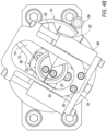
- the spindle 16 may include a biasing spring 68, as generally illustrated in FIG. 4A .
- the biasing spring 68 may include a compression spring and/or other suitable spring.
- the biasing spring 68 may be configured to bias the actuating plate 62 outward away from the central shaft 22.
- the assembly 10 may be conveyed through various bottle processing stations, as described.
- a component of the a bottle processing station may be configured to engage the cam follower 64.
- an actuating component of the processing station may apply a force on the cam follower 64 in the direction of the central shaft 22.
- the cam follower 64 may be configured to connect and/or engage with the actuating component.
- the actuating component may apply a force that is greater than a biasing force applied on the actuating plate 62 by a biasing mechanism, such as a biasing spring 68.
- the actuating plate 62 may actuate toward the central shaft 22 in response to the force being applied to the cam follower 64.
- the actuating plate 62 may move away from the central shaft 22 when the force being applied to the cam follower 64 is less than the biasing force applied to the actuating plate 62 by the biasing spring 68.
- the assembly 10 includes a locking cam 70.
- the locking cam 70 may be attached and/or connected to the bearing plate 42.
- the locking cam 70 may extend away from the bearing plate 42 toward the spindle 16.
- the locking cam 70 is configured to contact the cam follower 64 and in at least one position to limit movement of the actuating plate 62 toward the central shaft 22.
- the spindle 16 may rotate, as described.
- the cam follower 64 may make contact with the locking cam 70 in response to the spindle 16 rotating.
- the cam follower 64 may be forced outward away from the central shaft 22 in response to the cam follower 64 making contact with the locking cam 70.
- the actuating plate 62 would be actuated away from the central shaft 22 in response to the cam follower 64 being forced outward away from the central shaft 22.
- the bracket 28 may include a cam plate 72, as generally illustrated in FIGS. 3 and 11 .
- the cam plate 72 may be attached and/or connected, such as, to the actuating plate 62 via one or more fasteners.
- the fasteners may include, but are not limited to, socket head cap screws, screws, pins, dowel pins, rivets, weld joints, and/or other suitable fasteners.
- the cam plate 72 may include a follower track 74.
- the follower track 74 may comprise a recess, aperture and/or cutaway portion of the cam plate 72.
- the bracket 28 may include a standoff 76.
- the standoff 76 may be attached and/or connected to a tie bar and/or cross member 78, such as generally illustrated in FIG. 4A and 7 . Additionally, or alternatively, the standoff 76 may be attached and/or connected to an upper portion 80 of the bracket 28.
- a gripper 24 may be attached and/or connected to a portion of the bracket 28.
- the gripper 24 may include a first jaw 30 and a second jaw 32.
- the first jaw 30 may be attached and/or connected to the standoff 76.
- the first jaw 30 may be attached and/or connected to the standoff 76 via one or more fasteners.
- the fasteners may include, but are not limited to, socket head cap screws, screws, pins, dowel pins, rivets, weld joints, and/or other suitable fasteners.
- the first jaw 30 may be a stationary portion of the gripper 24.
- a bracket 28 may include one or more guide shafts 82.
- the one or more guide shafts 82 may extend between the cross member 78 and the upper portion 80.
- the upper portion 80 may include one or more projections 84.
- the one or more projections 84 may extend away from the upper portion 80.
- the one or more projections 84 may substantially align with the cross member 78.
- the one or more guide shafts 82 may include a corresponding bearing housing 86.
- the bearing housings 86 may include a plurality of ball bearings configured to roll and/or slide along corresponding guide shafts 82.
- a bracket 28 may include bridge plate 88.
- the bridge plate 88 may extend between the bearing housings 86.
- the second jaw 32 may be attached and/or connected to the bridge plate 88 via one or more fasteners.
- the fasteners may include, but are not limited to, socket head cap screws, screws, pins, dowel pins, rivets, weld joints, and/or other suitable fasteners.
- the bridge plate 88 may include a cam follower 90
- the cam follower 90 may be positioned within the follower track 74.
- the cam plate 72 may be configured to actuate and/or slide the cam follower 90 away from the central shaft 22.
- the cam plate 72 may be attached and/or connected to the actuating plate 62. As the actuating plate 62 is actuated toward the central shaft 22 (e.g., in response to the cam follower 64 being acted upon by a component of a processing station), the cam plate 72 may be actuated toward the central shaft 22.
- a cam follower 90 may be positioned within the follower track 74.
- the follower track 74 may be configured to guide the cam follower 90 away from the central shaft 22 as cam plate 72 is being actuated toward the central shaft 22.
- the bridge plate 88 may be pulled and/or slid away from the central shaft 22, in response to the cam follower 90 being guided by the follower track 74.
- the bearing housings 86 may roll and/or slid along the guide shafts 82.
- the second jaw 32 may be pulled and/or slid away from the first jaw 30 in response to the bridge plate 88 being pulled and/or slid away from the central shaft 22.
- an assembly 10 may be conveyed and/or provided to a bottle loading station associated with a bottle processing line.
- a component of the bottle loading station may apply a force on the cam follower 64.
- the actuating plate 62 actuating toward the central shaft 22 in response to the force being applied to the cam follower 64.
- the cam plate 72 may be actuated toward the central shaft 22 in response to the actuating plate 62 being actuated.
- the cam follower 90 may be guided by the follower track 74 in response to the cam plate 72 being actuated.
- the second jaw 32 may be pulled and/or slid away from the first jaw 30 in response to the cam follower 90 being guided by the follower track 74.
- a portion of a bottle may be inserted into a space between the first jaw 30 and the second jaw 32 by a bottle loading component of a bottle loading station.
- the force applied to the cam follower 64 may be reduced and/or removed.
- the actuating plate 62 may be actuated away from the central shaft 22 in response to a biasing force being applied by the biasing spring 68 on the actuating plate 62.
- the cam plate 72 may be pulled and/or forced away from the central shaft 22 by the actuating plate 62.
- the cam follower 90 may be guided by the follower track 74 toward the central shaft 22.
- the second jaw 32 may be pulled and/or slid toward the first jaw 30 in response to the cam follower 90 being guided by the follower track 74.
- the bottle inserted into the space between the first jaw 30 and the second jaw 32 may be gripped and/or held by the first jaw 30 and the second jaw 32.
- the spindle 16 may be rotated such that the cam follower 64 makes contact with the locking cam 70.
- the locking cam 70 may be configured to pull the cam follower 64 away from the central shaft 22 when the cam follower 64 makes contact with the locking cam 70.
- the second jaw 32 may be pulled and/or slid toward the first jaw 30.
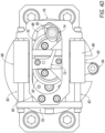
- the spindle 16 may be rotated to a locked position as generally illustrated in FIG. 4C .
- the locking cam 70 is configured to limit and/or prevent movement of the cam follower 64 in the direction of the central shaft 22.
- the cam follower 64 may be incidentally acted upon and/or actuated toward the central shaft 22.
- the locked cam 70 may prevent the cam follower 64 from actuating toward the central shaft 22, thereby preventing the second jaw 32 from being pulled and/or slid away from the first jaw 30 as described above. In this manner, the bottle is locked into the gripper 24.
- FIG. 5 generally illustrates a side view of a gripper assembly, including cross-section reference lines, embodying principles of the present disclosure.
- FIG. 8 generally illustrates a vertical cross-sectional view of a gripper assembly taken about line 8 as generally illustrated in FIG. 5 .
- FIG. 9 generally illustrates a horizontal cross-sectional view of a gripper assembly taken about line 9 as generally illustrated in FIG. 5 .
- FIG 10 generally illustrates a horizontal cross-sectional view of a gripper assembly taken about line 10 as generally illustrated in FIG. 5 .
- FIG. 11 generally illustrates a horizontal cross-sectional view taken about line 11 as illustrated in FIG. 5 .
- FIG. 12 generally illustrates a horizontal cross-sectional view of a gripper element taken about line 12 as illustrated in FIG. 5 .
Landscapes
- Engineering & Computer Science (AREA)
- Mechanical Engineering (AREA)
- Robotics (AREA)
- Filling Of Jars Or Cans And Processes For Cleaning And Sealing Jars (AREA)
- Specific Conveyance Elements (AREA)
Claims (11)
- Ensemble de préhension (10) pour saisir une partie d'un récipient, comprenant :un arbre central (22);une broche (16) configurée pour tourner autour d'un axe vertical ;un premier suiveur de came (64);une plaque d'actionnement (62); etune pince (24) configurée pour saisir une partie d'un récipient et comprenant une première mâchoire (30) et une deuxième mâchoire (32) formant une paire de mâchoires,la plaque d'actionnement (62) étant disposée sur ou autour de la broche (16), la plaque d'actionnement (62) étant configurée pour s'actionner vers l'arbre central (22) en réponse à l'application d'une force au premier suiveur de came (64) ;la pince (24) étant configurée pour au moins s'ouvrir et se fermer en réponse à l'actionnement de la plaque d'actionnement (62) vers l'arbre central (22); caractérisé parune came de verrouillage (70) configurée pour entrer en contact avec le premier suiveur de came (64) et dans au moins une position pour limiter le mouvement de la plaque d'actionnement (62) vers l'arbre central (22).
- Ensemble de préhension (10) selon la revendication 1, comprenant un ressort (68) configuré pour solliciter la plaque d'actionnement (62) à l'opposé de l'arbre central (22).
- Ensemble de préhension (10) selon la revendication 1 ou 2, comprenant un support (28) configuré pour supporter la pince (24).
- Ensemble de préhension (10) selon l'une quelconque des revendications 1 à 3, dans lequel la deuxième mâchoire (32) est configurée pour se déplacer ou pour se translater en s'éloignant de la première mâchoire (30) en réponse à l'actionnement de la plaque d'actionnement (62) vers l'arbre central (22).
- Ensemble de préhension (10) selon l'une quelconque des revendications 1 à 4, comprenant une plaque à came (72) disposée sur la plaque d'actionnement (62), la plaque à came (72) comprenant une piste de suiveur (74).
- Ensemble de préhension (10) selon la revendication 5, dans lequel la deuxième mâchoire (32) comprend un deuxième suiveur de came (90), en particulier dans lequel la piste de suiveur (74) est configurée pour guider le deuxième suiveur de came (90) à l'écart de l'arbre central (22) en réponse au déplacement ou à la translation de la plaque d'actionnement (62) vers l'arbre central (22)
- Ensemble de préhension (10) selon l'une quelconque des revendications 1 à 4, comprenant une plaque de came (72) configurée pour guider un deuxième suiveur de came (90) associé à au moins l'une des mâchoires (30, 32) à l'écart de l'arbre central (22).
- Ensemble de préhension (10) selon la revendication 7, dans lequel les mâchoires (30, 32) sont configurées pour s'ouvrir en réponse au guidage du deuxième suiveur de came (90) par la plaque de came (72).
- Ensemble de préhension (10) selon l'une quelconque des revendications 1 à 8, comprenant un anneau codeur (50) configuré pour indiquer une position de la broche.
- L'ensemble de préhension (10) selon la revendication 9, dans lequel la broche (16) est configurée pour être sélectivement tournée sur la base d'une position identifiée ou désignée.
- Ensemble de préhension (10) selon l'une quelconque des revendications 1 à 10, dans lequel la partie du récipient comprend une partie de col du récipient.
Applications Claiming Priority (2)
| Application Number | Priority Date | Filing Date | Title |
|---|---|---|---|
| US201662360706P | 2016-07-11 | 2016-07-11 | |
| PCT/US2017/041362 WO2018013478A1 (fr) | 2016-07-11 | 2017-07-10 | Élément de préhension de goulot comportant un verrouillage |
Publications (4)
| Publication Number | Publication Date |
|---|---|
| EP3481763A1 EP3481763A1 (fr) | 2019-05-15 |
| EP3481763A4 EP3481763A4 (fr) | 2020-05-20 |
| EP3481763C0 EP3481763C0 (fr) | 2024-02-28 |
| EP3481763B1 true EP3481763B1 (fr) | 2024-02-28 |
Family
ID=60953368
Family Applications (1)
| Application Number | Title | Priority Date | Filing Date |
|---|---|---|---|
| EP17828245.5A Active EP3481763B1 (fr) | 2016-07-11 | 2017-07-10 | Élément de préhension de goulot comportant un verrouillage |
Country Status (5)
| Country | Link |
|---|---|
| US (1) | US10836623B2 (fr) |
| EP (1) | EP3481763B1 (fr) |
| CA (1) | CA3030344C (fr) |
| MX (1) | MX2019000475A (fr) |
| WO (1) | WO2018013478A1 (fr) |
Families Citing this family (2)
| Publication number | Priority date | Publication date | Assignee | Title |
|---|---|---|---|---|
| CN111606282B (zh) * | 2020-05-21 | 2021-10-26 | 江苏亚盛休闲用品有限公司 | 一种对塑料罐进行液体灌装的设备 |
| US12326744B2 (en) * | 2023-02-23 | 2025-06-10 | Equashield Medical Ltd | Robotic pharmaceutical preparation system having a movable platform |
Family Cites Families (13)
| Publication number | Priority date | Publication date | Assignee | Title |
|---|---|---|---|---|
| US3590982A (en) * | 1969-05-19 | 1971-07-06 | Owens Illinois Inc | Article transfer apparatus |
| US3802942A (en) | 1971-12-20 | 1974-04-09 | Owens Illinois Inc | Machine for producing a plastic-covered glass container |
| US3860104A (en) | 1973-04-19 | 1975-01-14 | Indian Head Inc | Bottle conveyor system including adjustable height continuous belt conveyor and positive lock spray shielded rotatable bottle carrier |
| US3944058A (en) * | 1973-04-19 | 1976-03-16 | Indian Head Inc. | Bottle conveyor system including adjustable height continuous belt conveyor and positive lock spray shielded rotatable bottle carrier |
| ITMI20030194A1 (it) | 2003-02-05 | 2004-08-06 | Smi Spa | Stella con bracci a passo variabile per macchine rotative |
| DE10346044B4 (de) * | 2003-10-02 | 2016-04-28 | Khs Gmbh | Behandlungsmaschine für Behälter wie Flaschen, Dosen und dgl. |
| US7021453B2 (en) | 2003-11-13 | 2006-04-04 | Hartness International, Inc. | Conveyor with gear mechanism gripper and related conveyor link |
| DE102004034306B3 (de) * | 2004-07-15 | 2006-04-13 | Krones Ag | Greifer für Behälter und Behälterbehandlungsmaschine |
| DE102007054388A1 (de) | 2007-11-09 | 2009-05-14 | Khs Corpoplast Gmbh & Co. Kg | Vorrichtung zur Handhabung von Werkstücken |
| DE102009043984A1 (de) * | 2009-09-11 | 2011-03-17 | Krones Ag | Greifeinheit zum Haltern und Bewegen von Artikeln |
| FR2958275B1 (fr) | 2010-03-31 | 2012-08-10 | Sidel Participations | Dispositif pour le transport d'une preforme avec rotation de la preforme autour de son axe principal |
| DE202013101048U1 (de) * | 2013-03-11 | 2013-03-15 | Krones Ag | Vorrichtung zum Behandeln von Behältnissen mit Kunststoffführungsrollen aus Polyamidimid |
| IT201800003295A1 (it) * | 2018-03-06 | 2019-09-06 | Smi Spa | Dispositivo di manipolazione di contenitori dotato di pinze ad apertura comandata |
-
2017
- 2017-07-10 WO PCT/US2017/041362 patent/WO2018013478A1/fr not_active Ceased
- 2017-07-10 US US16/311,291 patent/US10836623B2/en active Active
- 2017-07-10 MX MX2019000475A patent/MX2019000475A/es unknown
- 2017-07-10 EP EP17828245.5A patent/EP3481763B1/fr active Active
- 2017-07-10 CA CA3030344A patent/CA3030344C/fr active Active
Also Published As
| Publication number | Publication date |
|---|---|
| MX2019000475A (es) | 2019-08-16 |
| US10836623B2 (en) | 2020-11-17 |
| US20190210858A1 (en) | 2019-07-11 |
| CA3030344C (fr) | 2023-09-19 |
| EP3481763A4 (fr) | 2020-05-20 |
| EP3481763C0 (fr) | 2024-02-28 |
| EP3481763A1 (fr) | 2019-05-15 |
| CA3030344A1 (fr) | 2018-01-18 |
| WO2018013478A1 (fr) | 2018-01-18 |
Similar Documents
| Publication | Publication Date | Title |
|---|---|---|
| US10265906B2 (en) | Device and method for transporting and handling containers | |
| CN102470996B (zh) | 用于星型输送机的夹持装置和星型输送机 | |
| EP2673118B1 (fr) | Robot avec ensemble de préhension | |
| US10000027B2 (en) | Apparatus and method for reshaping plastic preforms into plastic containers with an automatic changing device for handling parts | |
| EP3700846B1 (fr) | Appareil pour redresser des contenants disposés de manière aléatoire | |
| JP6985683B2 (ja) | ロボットシステム、ロボットシステムの制御方法および処理システム | |
| EP2617535A2 (fr) | Robot, main de robot et procédé de réglage de position de support de main de robot | |
| US20220306401A1 (en) | Clamp device and method for transporting a container | |
| CN104494116B (zh) | 具有换件机器人的吹塑机及其操作方法 | |
| EP3154881B1 (fr) | Système de transfert | |
| CN104552891A (zh) | 具有换件机器人的具备附加处理功能的吹塑机 | |
| CN107835786A (zh) | 用于保持容器的保持设备 | |
| KR20200040162A (ko) | 컨테이너용 이송 시스템 | |
| US20120205928A1 (en) | Gripper Assembly for Mechanical Device | |
| EP3481763B1 (fr) | Élément de préhension de goulot comportant un verrouillage | |
| CN113697473A (zh) | 夹紧设备和容器处理设备 | |
| EP3917863B1 (fr) | Système de manutention de conteneurs équipés d'un emballage et ayant un embout présentant un plan de symétrie traversante et méthode de manutention relative desdits conteneurs | |
| CN109963798B (zh) | 输送包括配有颈部的中空体的热塑性材料物件的系统 | |
| CN102639312A (zh) | 用于操作工件的装置 | |
| EP3321196B1 (fr) | Appareil et procédé pour emballer des produits dans des contenants préfabriqués | |
| EP3781500A1 (fr) | Dispositif de préhension de récipients | |
| US12115714B2 (en) | Gripper for holding workpieces, in particular preforms or containers | |
| JP2016011209A (ja) | ワーク搬送システム | |
| CN118871371A (zh) | 用于线性电驱动传送装置的控制概念 | |
| WO2026027051A1 (fr) | Pince multiformat pour bouteilles à mécanisme à double tige |
Legal Events
| Date | Code | Title | Description |
|---|---|---|---|
| STAA | Information on the status of an ep patent application or granted ep patent |
Free format text: STATUS: THE INTERNATIONAL PUBLICATION HAS BEEN MADE |
|
| PUAI | Public reference made under article 153(3) epc to a published international application that has entered the european phase |
Free format text: ORIGINAL CODE: 0009012 |
|
| STAA | Information on the status of an ep patent application or granted ep patent |
Free format text: STATUS: REQUEST FOR EXAMINATION WAS MADE |
|
| 17P | Request for examination filed |
Effective date: 20190208 |
|
| AK | Designated contracting states |
Kind code of ref document: A1 Designated state(s): AL AT BE BG CH CY CZ DE DK EE ES FI FR GB GR HR HU IE IS IT LI LT LU LV MC MK MT NL NO PL PT RO RS SE SI SK SM TR |
|
| AX | Request for extension of the european patent |
Extension state: BA ME |
|
| DAV | Request for validation of the european patent (deleted) | ||
| DAX | Request for extension of the european patent (deleted) | ||
| A4 | Supplementary search report drawn up and despatched |
Effective date: 20200420 |
|
| RIC1 | Information provided on ipc code assigned before grant |
Ipc: B25J 15/02 20060101ALI20200414BHEP Ipc: B67C 3/24 20060101AFI20200414BHEP Ipc: B65G 47/90 20060101ALI20200414BHEP |
|
| GRAP | Despatch of communication of intention to grant a patent |
Free format text: ORIGINAL CODE: EPIDOSNIGR1 |
|
| STAA | Information on the status of an ep patent application or granted ep patent |
Free format text: STATUS: GRANT OF PATENT IS INTENDED |
|
| INTG | Intention to grant announced |
Effective date: 20230309 |
|
| GRAJ | Information related to disapproval of communication of intention to grant by the applicant or resumption of examination proceedings by the epo deleted |
Free format text: ORIGINAL CODE: EPIDOSDIGR1 |
|
| GRAL | Information related to payment of fee for publishing/printing deleted |
Free format text: ORIGINAL CODE: EPIDOSDIGR3 |
|
| GRAS | Grant fee paid |
Free format text: ORIGINAL CODE: EPIDOSNIGR3 |
|
| STAA | Information on the status of an ep patent application or granted ep patent |
Free format text: STATUS: REQUEST FOR EXAMINATION WAS MADE |
|
| GRAP | Despatch of communication of intention to grant a patent |
Free format text: ORIGINAL CODE: EPIDOSNIGR1 |
|
| STAA | Information on the status of an ep patent application or granted ep patent |
Free format text: STATUS: GRANT OF PATENT IS INTENDED |
|
| INTC | Intention to grant announced (deleted) | ||
| INTG | Intention to grant announced |
Effective date: 20230804 |
|
| GRAA | (expected) grant |
Free format text: ORIGINAL CODE: 0009210 |
|
| STAA | Information on the status of an ep patent application or granted ep patent |
Free format text: STATUS: THE PATENT HAS BEEN GRANTED |
|
| AK | Designated contracting states |
Kind code of ref document: B1 Designated state(s): AL AT BE BG CH CY CZ DE DK EE ES FI FR GB GR HR HU IE IS IT LI LT LU LV MC MK MT NL NO PL PT RO RS SE SI SK SM TR |
|
| REG | Reference to a national code |
Ref country code: GB Ref legal event code: FG4D |
|
| REG | Reference to a national code |
Ref country code: CH Ref legal event code: EP |
|
| REG | Reference to a national code |
Ref country code: DE Ref legal event code: R096 Ref document number: 602017079597 Country of ref document: DE |
|
| REG | Reference to a national code |
Ref country code: IE Ref legal event code: FG4D |
|
| U01 | Request for unitary effect filed |
Effective date: 20240327 |
|
| U07 | Unitary effect registered |
Designated state(s): AT BE BG DE DK EE FI FR IT LT LU LV MT NL PT SE SI Effective date: 20240410 |
|
| PG25 | Lapsed in a contracting state [announced via postgrant information from national office to epo] |
Ref country code: IS Free format text: LAPSE BECAUSE OF FAILURE TO SUBMIT A TRANSLATION OF THE DESCRIPTION OR TO PAY THE FEE WITHIN THE PRESCRIBED TIME-LIMIT Effective date: 20240628 |
|
| PG25 | Lapsed in a contracting state [announced via postgrant information from national office to epo] |
Ref country code: GR Free format text: LAPSE BECAUSE OF FAILURE TO SUBMIT A TRANSLATION OF THE DESCRIPTION OR TO PAY THE FEE WITHIN THE PRESCRIBED TIME-LIMIT Effective date: 20240529 |
|
| PG25 | Lapsed in a contracting state [announced via postgrant information from national office to epo] |
Ref country code: RS Free format text: LAPSE BECAUSE OF FAILURE TO SUBMIT A TRANSLATION OF THE DESCRIPTION OR TO PAY THE FEE WITHIN THE PRESCRIBED TIME-LIMIT Effective date: 20240528 Ref country code: HR Free format text: LAPSE BECAUSE OF FAILURE TO SUBMIT A TRANSLATION OF THE DESCRIPTION OR TO PAY THE FEE WITHIN THE PRESCRIBED TIME-LIMIT Effective date: 20240228 |
|
| PG25 | Lapsed in a contracting state [announced via postgrant information from national office to epo] |
Ref country code: ES Free format text: LAPSE BECAUSE OF FAILURE TO SUBMIT A TRANSLATION OF THE DESCRIPTION OR TO PAY THE FEE WITHIN THE PRESCRIBED TIME-LIMIT Effective date: 20240228 |
|
| PG25 | Lapsed in a contracting state [announced via postgrant information from national office to epo] |
Ref country code: RS Free format text: LAPSE BECAUSE OF FAILURE TO SUBMIT A TRANSLATION OF THE DESCRIPTION OR TO PAY THE FEE WITHIN THE PRESCRIBED TIME-LIMIT Effective date: 20240528 Ref country code: NO Free format text: LAPSE BECAUSE OF FAILURE TO SUBMIT A TRANSLATION OF THE DESCRIPTION OR TO PAY THE FEE WITHIN THE PRESCRIBED TIME-LIMIT Effective date: 20240528 Ref country code: IS Free format text: LAPSE BECAUSE OF FAILURE TO SUBMIT A TRANSLATION OF THE DESCRIPTION OR TO PAY THE FEE WITHIN THE PRESCRIBED TIME-LIMIT Effective date: 20240628 Ref country code: HR Free format text: LAPSE BECAUSE OF FAILURE TO SUBMIT A TRANSLATION OF THE DESCRIPTION OR TO PAY THE FEE WITHIN THE PRESCRIBED TIME-LIMIT Effective date: 20240228 Ref country code: GR Free format text: LAPSE BECAUSE OF FAILURE TO SUBMIT A TRANSLATION OF THE DESCRIPTION OR TO PAY THE FEE WITHIN THE PRESCRIBED TIME-LIMIT Effective date: 20240529 Ref country code: ES Free format text: LAPSE BECAUSE OF FAILURE TO SUBMIT A TRANSLATION OF THE DESCRIPTION OR TO PAY THE FEE WITHIN THE PRESCRIBED TIME-LIMIT Effective date: 20240228 |
|
| PG25 | Lapsed in a contracting state [announced via postgrant information from national office to epo] |
Ref country code: PL Free format text: LAPSE BECAUSE OF FAILURE TO SUBMIT A TRANSLATION OF THE DESCRIPTION OR TO PAY THE FEE WITHIN THE PRESCRIBED TIME-LIMIT Effective date: 20240228 |
|
| PG25 | Lapsed in a contracting state [announced via postgrant information from national office to epo] |
Ref country code: PL Free format text: LAPSE BECAUSE OF FAILURE TO SUBMIT A TRANSLATION OF THE DESCRIPTION OR TO PAY THE FEE WITHIN THE PRESCRIBED TIME-LIMIT Effective date: 20240228 |
|
| PG25 | Lapsed in a contracting state [announced via postgrant information from national office to epo] |
Ref country code: SM Free format text: LAPSE BECAUSE OF FAILURE TO SUBMIT A TRANSLATION OF THE DESCRIPTION OR TO PAY THE FEE WITHIN THE PRESCRIBED TIME-LIMIT Effective date: 20240228 |
|
| PG25 | Lapsed in a contracting state [announced via postgrant information from national office to epo] |
Ref country code: CZ Free format text: LAPSE BECAUSE OF FAILURE TO SUBMIT A TRANSLATION OF THE DESCRIPTION OR TO PAY THE FEE WITHIN THE PRESCRIBED TIME-LIMIT Effective date: 20240228 |
|
| PG25 | Lapsed in a contracting state [announced via postgrant information from national office to epo] |
Ref country code: SK Free format text: LAPSE BECAUSE OF FAILURE TO SUBMIT A TRANSLATION OF THE DESCRIPTION OR TO PAY THE FEE WITHIN THE PRESCRIBED TIME-LIMIT Effective date: 20240228 |
|
| PG25 | Lapsed in a contracting state [announced via postgrant information from national office to epo] |
Ref country code: SM Free format text: LAPSE BECAUSE OF FAILURE TO SUBMIT A TRANSLATION OF THE DESCRIPTION OR TO PAY THE FEE WITHIN THE PRESCRIBED TIME-LIMIT Effective date: 20240228 Ref country code: SK Free format text: LAPSE BECAUSE OF FAILURE TO SUBMIT A TRANSLATION OF THE DESCRIPTION OR TO PAY THE FEE WITHIN THE PRESCRIBED TIME-LIMIT Effective date: 20240228 Ref country code: RO Free format text: LAPSE BECAUSE OF FAILURE TO SUBMIT A TRANSLATION OF THE DESCRIPTION OR TO PAY THE FEE WITHIN THE PRESCRIBED TIME-LIMIT Effective date: 20240228 Ref country code: CZ Free format text: LAPSE BECAUSE OF FAILURE TO SUBMIT A TRANSLATION OF THE DESCRIPTION OR TO PAY THE FEE WITHIN THE PRESCRIBED TIME-LIMIT Effective date: 20240228 |
|
| REG | Reference to a national code |
Ref country code: DE Ref legal event code: R097 Ref document number: 602017079597 Country of ref document: DE |
|
| PLBE | No opposition filed within time limit |
Free format text: ORIGINAL CODE: 0009261 |
|
| STAA | Information on the status of an ep patent application or granted ep patent |
Free format text: STATUS: NO OPPOSITION FILED WITHIN TIME LIMIT |
|
| 26N | No opposition filed |
Effective date: 20241129 |
|
| PG25 | Lapsed in a contracting state [announced via postgrant information from national office to epo] |
Ref country code: MC Free format text: LAPSE BECAUSE OF FAILURE TO SUBMIT A TRANSLATION OF THE DESCRIPTION OR TO PAY THE FEE WITHIN THE PRESCRIBED TIME-LIMIT Effective date: 20240228 |
|
| REG | Reference to a national code |
Ref country code: CH Ref legal event code: PL |
|
| U90 | Renewal fees not paid: noting of loss of rights |
Free format text: RENEWAL FEE NOT PAID FOR YEAR 08 Effective date: 20250214 |
|
| PG25 | Lapsed in a contracting state [announced via postgrant information from national office to epo] |
Ref country code: CH Free format text: LAPSE BECAUSE OF NON-PAYMENT OF DUE FEES Effective date: 20240731 |
|
| U50 | Request for re-establishment of rights filed [unitary effect] |
Free format text: RE-ESTABLISHMENT OF RIGHTS REQUESTED DUE TO A NOTIFICATION OF LAPSE Effective date: 20250325 |
|
| PG25 | Lapsed in a contracting state [announced via postgrant information from national office to epo] |
Ref country code: IE Free format text: LAPSE BECAUSE OF NON-PAYMENT OF DUE FEES Effective date: 20240710 |
|
| U20 | Renewal fee for the european patent with unitary effect paid |
Year of fee payment: 9 Effective date: 20250728 |
|
| U53 | Request for re-establishment of rights accepted [unitary effect] |
Effective date: 20250827 |
|
| U20 | Renewal fee for the european patent with unitary effect paid |
Year of fee payment: 9 Effective date: 20250728 |
|
| PGFP | Annual fee paid to national office [announced via postgrant information from national office to epo] |
Ref country code: GB Payment date: 20250722 Year of fee payment: 9 |
|
| PG25 | Lapsed in a contracting state [announced via postgrant information from national office to epo] |
Ref country code: CY Free format text: LAPSE BECAUSE OF FAILURE TO SUBMIT A TRANSLATION OF THE DESCRIPTION OR TO PAY THE FEE WITHIN THE PRESCRIBED TIME-LIMIT; INVALID AB INITIO Effective date: 20170710 |
|
| PG25 | Lapsed in a contracting state [announced via postgrant information from national office to epo] |
Ref country code: HU Free format text: LAPSE BECAUSE OF FAILURE TO SUBMIT A TRANSLATION OF THE DESCRIPTION OR TO PAY THE FEE WITHIN THE PRESCRIBED TIME-LIMIT; INVALID AB INITIO Effective date: 20170710 |