EP3482016B1 - Dispositif d'écran - Google Patents
Dispositif d'écran Download PDFInfo
- Publication number
- EP3482016B1 EP3482016B1 EP18747020.8A EP18747020A EP3482016B1 EP 3482016 B1 EP3482016 B1 EP 3482016B1 EP 18747020 A EP18747020 A EP 18747020A EP 3482016 B1 EP3482016 B1 EP 3482016B1
- Authority
- EP
- European Patent Office
- Prior art keywords
- collector
- screen device
- spout
- seal
- shaped piece
- Prior art date
- Legal status (The legal status is an assumption and is not a legal conclusion. Google has not performed a legal analysis and makes no representation as to the accuracy of the status listed.)
- Active
Links
Images




Classifications
-
- E—FIXED CONSTRUCTIONS
- E04—BUILDING
- E04F—FINISHING WORK ON BUILDINGS, e.g. STAIRS, FLOORS
- E04F10/00—Sunshades, e.g. Florentine blinds or jalousies; Outside screens; Awnings or baldachins
-
- E—FIXED CONSTRUCTIONS
- E04—BUILDING
- E04F—FINISHING WORK ON BUILDINGS, e.g. STAIRS, FLOORS
- E04F10/00—Sunshades, e.g. Florentine blinds or jalousies; Outside screens; Awnings or baldachins
- E04F10/02—Sunshades, e.g. Florentine blinds or jalousies; Outside screens; Awnings or baldachins of flexible canopy materials, e.g. canvas ; Baldachins
- E04F10/06—Sunshades, e.g. Florentine blinds or jalousies; Outside screens; Awnings or baldachins of flexible canopy materials, e.g. canvas ; Baldachins comprising a roller-blind with means for holding the end away from a building
- E04F10/0685—Covers or housings for the rolled-up blind
-
- E—FIXED CONSTRUCTIONS
- E04—BUILDING
- E04H—BUILDINGS OR LIKE STRUCTURES FOR PARTICULAR PURPOSES; SWIMMING OR SPLASH BATHS OR POOLS; MASTS; FENCING; TENTS OR CANOPIES, IN GENERAL
- E04H6/00—Buildings for parking cars, rolling-stock, aircraft, vessels or like vehicles, e.g. garages
- E04H6/02—Small garages, e.g. for one or two cars
- E04H6/025—Small garages, e.g. for one or two cars in the form of an overhead canopy, e.g. carports
-
- E—FIXED CONSTRUCTIONS
- E04—BUILDING
- E04B—GENERAL BUILDING CONSTRUCTIONS; WALLS, e.g. PARTITIONS; ROOFS; FLOORS; CEILINGS; INSULATION OR OTHER PROTECTION OF BUILDINGS
- E04B1/00—Constructions in general; Structures which are not restricted either to walls, e.g. partitions, or floors or ceilings or roofs
- E04B1/0046—Loggias
-
- E—FIXED CONSTRUCTIONS
- E04—BUILDING
- E04B—GENERAL BUILDING CONSTRUCTIONS; WALLS, e.g. PARTITIONS; ROOFS; FLOORS; CEILINGS; INSULATION OR OTHER PROTECTION OF BUILDINGS
- E04B1/00—Constructions in general; Structures which are not restricted either to walls, e.g. partitions, or floors or ceilings or roofs
- E04B1/18—Structures comprising elongated load-supporting parts, e.g. columns, girders, skeletons
- E04B1/24—Structures comprising elongated load-supporting parts, e.g. columns, girders, skeletons the supporting parts consisting of metal
- E04B1/2403—Connection details of the elongated load-supporting parts
- E04B2001/2409—Hooks, dovetails or other interlocking connections
-
- E—FIXED CONSTRUCTIONS
- E04—BUILDING
- E04B—GENERAL BUILDING CONSTRUCTIONS; WALLS, e.g. PARTITIONS; ROOFS; FLOORS; CEILINGS; INSULATION OR OTHER PROTECTION OF BUILDINGS
- E04B1/00—Constructions in general; Structures which are not restricted either to walls, e.g. partitions, or floors or ceilings or roofs
- E04B1/18—Structures comprising elongated load-supporting parts, e.g. columns, girders, skeletons
- E04B1/24—Structures comprising elongated load-supporting parts, e.g. columns, girders, skeletons the supporting parts consisting of metal
- E04B1/2403—Connection details of the elongated load-supporting parts
- E04B2001/2451—Connections between closed section profiles
-
- E—FIXED CONSTRUCTIONS
- E04—BUILDING
- E04C—STRUCTURAL ELEMENTS; BUILDING MATERIALS
- E04C3/00—Structural elongated elements designed for load-supporting
- E04C3/02—Joists; Girders, trusses, or trusslike structures, e.g. prefabricated; Lintels; Transoms; Braces
- E04C3/04—Joists; Girders, trusses, or trusslike structures, e.g. prefabricated; Lintels; Transoms; Braces of metal
- E04C2003/0404—Joists; Girders, trusses, or trusslike structures, e.g. prefabricated; Lintels; Transoms; Braces of metal beams, girders, or joists characterised by cross-sectional aspects
- E04C2003/0408—Joists; Girders, trusses, or trusslike structures, e.g. prefabricated; Lintels; Transoms; Braces of metal beams, girders, or joists characterised by cross-sectional aspects characterised by assembly or the cross-section
- E04C2003/0413—Joists; Girders, trusses, or trusslike structures, e.g. prefabricated; Lintels; Transoms; Braces of metal beams, girders, or joists characterised by cross-sectional aspects characterised by assembly or the cross-section being built up from several parts
- E04C2003/0417—Joists; Girders, trusses, or trusslike structures, e.g. prefabricated; Lintels; Transoms; Braces of metal beams, girders, or joists characterised by cross-sectional aspects characterised by assembly or the cross-section being built up from several parts demountable
-
- E—FIXED CONSTRUCTIONS
- E04—BUILDING
- E04C—STRUCTURAL ELEMENTS; BUILDING MATERIALS
- E04C3/00—Structural elongated elements designed for load-supporting
- E04C3/02—Joists; Girders, trusses, or trusslike structures, e.g. prefabricated; Lintels; Transoms; Braces
- E04C3/04—Joists; Girders, trusses, or trusslike structures, e.g. prefabricated; Lintels; Transoms; Braces of metal
- E04C2003/0404—Joists; Girders, trusses, or trusslike structures, e.g. prefabricated; Lintels; Transoms; Braces of metal beams, girders, or joists characterised by cross-sectional aspects
- E04C2003/0426—Joists; Girders, trusses, or trusslike structures, e.g. prefabricated; Lintels; Transoms; Braces of metal beams, girders, or joists characterised by cross-sectional aspects characterised by material distribution in cross section
- E04C2003/0439—Joists; Girders, trusses, or trusslike structures, e.g. prefabricated; Lintels; Transoms; Braces of metal beams, girders, or joists characterised by cross-sectional aspects characterised by material distribution in cross section the cross-section comprising open parts and hollow parts
-
- E—FIXED CONSTRUCTIONS
- E04—BUILDING
- E04C—STRUCTURAL ELEMENTS; BUILDING MATERIALS
- E04C3/00—Structural elongated elements designed for load-supporting
- E04C3/02—Joists; Girders, trusses, or trusslike structures, e.g. prefabricated; Lintels; Transoms; Braces
- E04C3/04—Joists; Girders, trusses, or trusslike structures, e.g. prefabricated; Lintels; Transoms; Braces of metal
- E04C2003/0404—Joists; Girders, trusses, or trusslike structures, e.g. prefabricated; Lintels; Transoms; Braces of metal beams, girders, or joists characterised by cross-sectional aspects
- E04C2003/0443—Joists; Girders, trusses, or trusslike structures, e.g. prefabricated; Lintels; Transoms; Braces of metal beams, girders, or joists characterised by cross-sectional aspects characterised by substantial shape of the cross-section
- E04C2003/046—L- or T-shaped
-
- E—FIXED CONSTRUCTIONS
- E04—BUILDING
- E04D—ROOF COVERINGS; SKY-LIGHTS; GUTTERS; ROOF-WORKING TOOLS
- E04D13/00—Special arrangements or devices in connection with roof coverings; Protection against birds; Roof drainage ; Sky-lights
- E04D13/04—Roof drainage; Drainage fittings in flat roofs, balconies or the like
- E04D13/08—Down pipes; Special clamping means therefor
- E04D2013/0893—Down pipes; Special clamping means therefor incorporated in building structure
-
- E—FIXED CONSTRUCTIONS
- E06—DOORS, WINDOWS, SHUTTERS, OR ROLLER BLINDS IN GENERAL; LADDERS
- E06B—FIXED OR MOVABLE CLOSURES FOR OPENINGS IN BUILDINGS, VEHICLES, FENCES OR LIKE ENCLOSURES IN GENERAL, e.g. DOORS, WINDOWS, BLINDS, GATES
- E06B9/00—Screening or protective devices for wall or similar openings, with or without operating or securing mechanisms; Closures of similar construction
- E06B9/24—Screens or other constructions affording protection against light, especially against sunshine; Similar screens for privacy or appearance; Slat blinds
- E06B9/40—Roller blinds
- E06B2009/405—Two rollers
Definitions
- This invention relates to a screen device comprising
- Screen devices to which this invention relates are generally arranged to screen, or conversely to liberate, an outdoor space.
- screen devices of this type are frequently arranged in dwellings, restaurants, shops and the like in order to screen an outside terrace or the like from sunrays, precipitation and/or wind, or, conversely, to temporarily admit sunrays.
- These screen devices can be constructed in the form of awnings, pergolas, verandas, terrace canopies, carports, etc.
- a screen construction of this type typically comprises a roof construction (canopy) which is at least partially supported by columns.
- the canopy generally comprises a plurality of beams as construction elements, which are assembled to form one or more frameworks.
- a framework of this type is typically supported on four (or more) columns or is typically fastened on one or more sides, for support purposes, to a wall, and supported on another side by two (or more) columns.
- the columns are - just like the beams - construction elements of the screen device.
- a beam can be fastened to an adjacent beam as an adjacent construction element, and/or to a column as an adjacent construction element.
- the canopy can be of fixed construction, or can comprise a rollable and unrollable screen, or can comprise slats, etc., whether rotatable and/or retractable or not.
- the screen devices of this type are often provided with electrical apparatus such as lighting and/or heating. Furthermore, these screen devices are laterally also often provided with screens in order to screen the opening between two columns. This opening can herein be screened, for example, with a screen which is rollable and unreliable on a screen roller. It is also possible for sliding walls to be provided herein.
- a screen device of this type having a said end plate and a said collector is known, for example, from WO2015104675A1 .
- a problem with the screen devices of this type is, however, to ensure the water tightness of the connection of the spout-shaped piece on top of the edge of the collector.
- the object of this invention is to at least partially remedy the said problems and to obtain an improved water tightness of the said connection.
- the collector in the screen device such that it is fastenable in a height-adjustable manner at more than one point, more control is established over the positioning thereof, irrespective of a correct alignment of other components of the screen device relative to one another. In this way, this collector can be more accurately connected up to the spout-shaped piece, without, for this purpose, damaging the seal.
- the collector By providing the collector such that it is adjustable in height at two points, a certain tilting relative to the spout-shaped piece can already be realized.
- the collector is, however, provided such that it is adjustable in height at at least 3 points which are not all in line, so that the collector can be tilted in more than one direction relative to this spout-shaped piece.
- the said adjacent construction element can in this case, for example, be another beam of the screen device, or can be a column of the screen device.
- the adjacent construction element is an adjacent beam
- precipitation is typically passed, via the collector, between the beams.
- the adjacent construction element is a column
- precipitation passed via the collector is drained off via this column.
- this collector can be provided in a height-adjustable manner on top of the column.
- the column itself is then preferably provided with a drainpipe in its cavity.
- the collector is then preferably provided with a connecting piece in order to connect it to this drainpipe in order to let precipitation flow into the cavity of the column.
- the fastening means preferably comprise a fastening body, which forms part of or is fastened to the beam and/or the adjacent construction element, for the height-adjustable fastening of the collector hereto.
- This fastening body can in this case, for example, form part of or be fastened to the said end plate.
- a screen device of this type can comprise one such fastening body for all points, or can comprise a plurality of fastening bodies which are each provided for the height adjustment of the collector at one or more of the said points. With a view to ease of assembly, preferably only one such fastening body is provided for all points.
- the said fastening body extends in the mounted state, at the said points, above the collector.
- the collector is then, at the said points, suspended from this fastening body and raised to a greater or lesser extent towards this fastening body in order to provide its height adjustability.
- the fastening means comprise for each point an adjusting screw for the, at that point, height-adjustable fastening of the collector to the fastening body.
- the collector is preferably, for each point, provided with a cavity having an internal screw thread, conforming to the external screw thread of the corresponding adjusting screw.
- the collector is preferably provided with a raised edge, which is constructed such that it tapers towards the fastening body. With the aid of a raised edge of this type, precipitation which is passed via the collector can be easily kept away from the herewith demarcated cavity with internal screw thread.
- At least one said point, in the mounted state is preferably arranged adjacent to the spout-shaped piece. If a plurality of spout-shaped pieces of a plurality of head pieces can connect to a plurality of beams on a collector of this type, such a point is preferably provided in the area of each of these spout-shaped pieces.
- the said edge of the collector preferably comprises at least one insertion cavity, into which the spout-shaped piece is placeable in order to fit this on top of this edge.
- a plurality of such insertion cavities can be provided for the connection of a plurality of corresponding spout-shaped pieces to this collector.
- a collector can, for example, be standardly provided with the maximum number of such insertion cavities which might be necessary in a screen device, wherein these insertion cavities can initially be closed off with the aid of a fill-in element. Where necessary, this fill-in element can then be removed in order to make room for a spout-shaped piece which is to be fitted herein.
- a screen device preferably further comprises a sealant, which is fitted, at the said edge of the collector, between the collector and the spout-shaped piece.
- sealant can be used.
- This sealant can be applied, for example, in the form of a silicone. This is, however, rather laborious and not very reliable, given that the accurate application thereof is heavily dependent on the persons who fit the screen device. Preferredly, this sealant is therefore rather provided in the form of a seal.
- the said edge of the collector is preferably provided, in addition to this seal, with a raised edge, which rises less high than the seal. With the aid of a raised edge of this type, possible damage to the seal as a result of the over-hard tensioning of the collector against the spout-shaped piece can be avoided.
- the seal itself is preferably centrally provided with a raised rib, which on both sides is bounded by a groove in the seal. In this way, the material of the seal, when the collector is tensioned against the spout-shaped piece, can be neatly distributed without the seal being hereupon torn. If the said edge of the collector is here also provided with a said raised edge, then the grooves in the seal preferably extend below this raised edge, whilst the raised rib rises above this raised edge.
- the seal and the collector form part of a same piece. This again reduces the risk of mispositioning of the seal as a result of snarling, for example, and possible damaging of the rib.
- the seal can herein be formed, for example, by co-injection moulding with the collector.
- the collector is realized as a collecting basin.
- this seal in the mounted state, is preferably fitted over the complete top edge of the collecting basin.
- the screen device (1) depicted in Figure 7 comprises a plurality of beams (3), as construction elements, which are assembled into frameworks which, on the one hand, are fastened to existing buildings (32) and, on the other hand, are supported by a plurality of columns (5) as construction elements of the screen device (1).
- the screen device (1) also comprises fill-in elements (not depicted) for forming a, whether movable or immovable, filling of the frameworks as a canopy (2) and possible, whether movable or immovable, wall-forming fill-in elements (not depicted).
- Filling elements for filling in the frameworks as a canopy (2) can be fixed fill-in elements or movable fill-in elements.
- the movable fill-in elements are typically screens which are rollable and unrollable on a screen roller, and/or tiltable and/or retractable slats, etc.
- the movable fill-in elements form in the closed position a watertight roof, which is typically drained of water towards the beams (3) and, from there, via adjacent beams (3) and/or columns (5).
- this roof can be at least partially opened and/or closed in order thus, according to choice, to admit sun and/or wind, or else screen these off.
- Wall-forming fill-in elements are typically intended to screen openings under the canopy (2), between columns (5). These can likewise be fixed fill-in elements or movable fill-in elements. Movable fill-in elements are typically screens which are rollable and unrollable on a screen roller, or wall elements which are arranged displaceably relative to one another, etc.
- the beams (3) and columns (5), or parts thereof, can be produced from aluminium, for example by extrusion. It is also conceivable to produce these beams (3) and columns (5), for example, from steel, or from stainless steel, or from wood, etc.
- the beams (3) are of hollow construction and are provided with an internal gutter (6) for the drainage of precipitation falling on the canopy (2).
- One or more columns (5) may also be of hollow construction for the further drainage of this precipitation from the beams (3).
- the beams (3) and the columns (5) are mutually connected with the aid of end plates (7, 22).
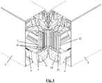
- An example of such a coupling of a beam (3) to an adjacent beam (4) as the adjacent construction element is depicted in Figure 1 .
- a beam (3) of this type can also be coupled to a column (5) as the adjacent construction element.
- the end plates (7, 22) respectively comprise a flow-through opening (8), which, after fastening of the end plate (7, 22) onto a corresponding beam (3, 4), connects to the internal gutter (6) thereof in order to allow precipitation drained off with this beam (3) to flow through here, or to allow precipitation to flow through here from an adjacent beam (3) into the cavity (10) of this beam (4) in order to further drain it off via the internal gutter (6) hereof.
- the screen device (1) further comprises collectors (11) which correspond with the end plates (7, 22) and which are provided to be mounted connecting to the flow-through opening (8), as can be seen in Figures 4 to 6 .
- the end plates (7, 22) Adjoining the flow-through opening (8), the end plates (7, 22) comprise a spout-shaped piece (9, 23).
- the collectors (11) are realized as a collecting basin, which at their top edge (12) comprise four insertion cavities (17), so that the necessary spout-shaped pieces (9, 23) can be fitted herein.
- two of the four insertion cavities (17) are provided with a fill-in element (31). It is possible to initially provide all insertion cavities (17) with such a fill-in element (31) and only to liberate only those insertion cavities (17) where a connection of a spout-shaped piece (9) hereto is necessary.
- a collector (11) which is provided for a connection between two beams (3, 4), without support of a column (5), in order herewith to transfer precipitation of the internal gutter (6) out of the one beam (3) to the internal gutter (6) of the other beam (4).
- This screen device (1) may also comprise one or more collectors, which are provided for a connection of a beam (3) to a column (5), wherein this collector is then preferably provided with a connector for connecting this collector to a drainpipe which can be fitted in the cavity of the column (5).
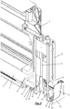
- the screen device (1) comprises a fastening body (13), which is fastenable to the end plates (7, 22) and for this purpose is provided with holes (29), in which pins (30) on the end plates (7, 22) can be fitted.
- adjusting screws (14) which at the bottom are provided with an external screw thread, corresponding with an internal screw thread in cavities (15) which are provided in the collector (11).
- the inclination of the collector (11) can in this way be adjusted relative to both beams (3, 4), and this irrespective of the accuracy with which both beams (3, 4) are aligned relative to each other.
- the said points (15) are respectively arranged adjacent to a said insertion cavity (17).
- the collector (11) is provided with a raised edge (16), which is constructed such that it tapers towards the fastening body (13). Precipitation which flows through the collector (11) is in this way kept away from these cavities (15).
- a fastening plate (27) can be fastened, this, for example, with the aid of a screw which engages in the central duct (25) in the collector (11). This screw can possibly be tightened through the central duct (24) in the fastening body (13).
- a finishing plate (26) can underneath be fastened, wherein the inclination of the finishing plate (26) relative to the inclination of the collector (11) can be adapted, for example, with the aid of spacers (28), the height of which can for this purpose be adapted by breaking off or sawing off a part of these spacers (28). In this way, the aesthetic end result of the connection of the beams (3, 4) is completely decoupled from the positioning of the collector (11).
- the top edge (12) of the collector (11) is provided with a seal (18), which in the mounted state seals the connection between the collector (11) and the spout-shaped piece (9, 23).
- the top edge (12) is provided with a raised edge (21), which defines the boundary to where the collector (11) can be tensioned against the spout-shaped piece (9, 23), so that the seal (18) cannot get damaged but ensures a satisfactory sealing.
- the seal (18) is further provided with a central raised rib (19), which rises above this raised edge (21) and which on both sides is bounded by a groove (20) in the seal (18), which groove extends less high than the raised edge (21), this in order to still further limit the chance of damage to the seal (18).
Landscapes
- Engineering & Computer Science (AREA)
- Architecture (AREA)
- Civil Engineering (AREA)
- Structural Engineering (AREA)
- Roof Covering Using Slabs Or Stiff Sheets (AREA)
- Catching Or Destruction (AREA)
Claims (15)
- Dispositif de protection (1) comprenant :- un auvent (2), qui comprend une poutre (3), dans lequel cette poutre (3) peut être fixée à au moins un élément de construction adjacent (4) du dispositif de protection (1) et comprend une gouttière interne (6) pour le drainage des précipitations tombant sur l'auvent (2) ;- une plaque d'extrémité (7) pouvant être fixée à une extrémité de la poutre (3) ou faisant partie d'une extrémité de celle-ci, pour fixer la poutre (3) à l'élément de construction adjacent (4), et qui est pourvue d'une ouverture de passage (8) et d'une pièce en forme de bec (9) attenante à cette ouverture de passage (8), afin de permettre aux précipitations de s'écouler par cette ouverture (8) et cette pièce en forme de bec (9) hors de la gouttière interne (6) dans une cavité (10) de l'élément de construction adjacent (4) ;- et un collecteur (11), qui peut être placé entre la poutre (3) et l'élément de construction adjacent (4), de manière attenante à la pièce en forme de bec (9) de la plaque d'extrémité (7) et de manière attenante à la cavité (10) de l'élément de construction adjacent (4), pour le passage des précipitations drainées de la pièce en forme de bec (9) vers la cavité (10) de l'élément de construction adjacent (4), la pièce en forme de bec (9) étant ajustée au-dessus d'un bord (12) du collecteur (11) ;le dispositif de protection (1) comprenant des moyens de fixation (13, 14) pour fixer le collecteur (11) dans le dispositif de protection (1) de telle sorte que ledit collecteur soit réglable en hauteur sur plusieurs points (15) .
- Dispositif de protection (1) selon la revendication 1, caractérisé en ce que les moyens de fixation (13, 14) comprennent un corps de fixation (13) qui fait partie de la poutre (3) et/ou de l'élément de construction adjacent (4) ou qui est fixé à ceux-ci, pour la fixation réglable en hauteur du collecteur (11).
- Dispositif de protection (1) selon la revendication 2, caractérisé en ce que le corps de fixation (13) s'étend à l'état monté, au niveau desdits points (15), au-dessus du collecteur (11).
- Dispositif de protection (1) selon l'une des revendications 2 et 3, caractérisé en ce que les moyens de fixation (13, 14) comprennent pour chaque point (15) une vis de réglage (14) pour la fixation réglable en hauteur, à ce point (15), du collecteur (11) sur le corps de fixation (13).
- Dispositif de protection (1) selon les revendications 3 et 4, caractérisé en ce que le collecteur (11) est pourvu, pour chaque point (15), d'une cavité présentant un filetage intérieur (15) conforme au filetage extérieur de la vis de réglage (14) correspondante, et autour de cette cavité (14) comprend un bord surélevé (16) qui, vu à l'état monté, est réalisé de telle façon qu'il diminue progressivement vers le corps de fixation (13).
- Dispositif de protection (1) selon l'une des revendications précédentes, caractérisé en ce qu'au moins un desdits points (15), à l'état monté, est disposé de manière attenante à la pièce en forme de bec (9).
- Dispositif de protection (1) selon l'une des revendications précédentes, caractérisé en ce que ledit bord (12) du collecteur (11) comporte au moins une cavité d'insertion (17), dans laquelle la pièce en forme de bec (9) peut être placée afin d'ajuster celle-ci au-dessus de ce bord (12).
- Dispositif de protection (1) selon l'une des revendications précédentes, le dispositif de protection (1) comprenant un matériau d'étanchéité (18) qui, à l'état monté, est ajusté sur ledit bord (12) du collecteur (11), entre le collecteur (11) et la pièce en forme de bec (9).
- Dispositif de protection (1) selon la revendication 8, caractérisé en ce que le matériau d'étanchéité (18) est prévu sous la forme d'un joint d'étanchéité (18).
- Dispositif de protection (1) selon la revendication 9, caractérisé en ce que ledit bord (12) du collecteur (11) est pourvu, en plus du joint d'étanchéité (18), d'un bord surélevé (21), qui monte moins haut que le joint d'étanchéité (18).
- Dispositif de protection (1) selon la revendication 9 ou 10, caractérisé en ce que le joint d'étanchéité (18) est pourvu au centre d'une nervure surélevée (19) qui est limitée des deux côtés par une rainure (20) dans le joint d'étanchéité (18).
- Dispositif de protection (1) selon l'une des revendications 9 à 11, caractérisé en ce que le joint d'étanchéité (18) et le collecteur (11) font partie d'une même pièce.
- Dispositif de protection (1) selon la revendication 12, caractérisé en ce que le joint d'étanchéité (18) est formé par moulage par co-injection avec le collecteur (11) .
- Dispositif de protection (1) selon l'une des revendications précédentes, caractérisé en ce que le collecteur (11) est réalisé sous la forme d'un bassin collecteur (11).
- Dispositif de protection (1) selon l'une des revendications 9 à 13 et 14, caractérisé en ce que le joint d'étanchéité (18), à l'état monté, est ajusté sur le bord supérieur complet (12) du bassin collecteur (11).
Applications Claiming Priority (2)
| Application Number | Priority Date | Filing Date | Title |
|---|---|---|---|
| BE2017/5506A BE1025403B1 (nl) | 2017-07-17 | 2017-07-17 | Scherminrichting |
| PCT/IB2018/055234 WO2019053523A1 (fr) | 2017-07-17 | 2018-07-16 | Dispositif de protection |
Publications (2)
| Publication Number | Publication Date |
|---|---|
| EP3482016A1 EP3482016A1 (fr) | 2019-05-15 |
| EP3482016B1 true EP3482016B1 (fr) | 2020-01-22 |
Family
ID=59506015
Family Applications (1)
| Application Number | Title | Priority Date | Filing Date |
|---|---|---|---|
| EP18747020.8A Active EP3482016B1 (fr) | 2017-07-17 | 2018-07-16 | Dispositif d'écran |
Country Status (3)
| Country | Link |
|---|---|
| EP (1) | EP3482016B1 (fr) |
| BE (1) | BE1025403B1 (fr) |
| WO (1) | WO2019053523A1 (fr) |
Families Citing this family (3)
| Publication number | Priority date | Publication date | Assignee | Title |
|---|---|---|---|---|
| US10851544B1 (en) * | 2020-01-07 | 2020-12-01 | Dee Volin | Multi-function wind-directing leaf-separating-and-discharging rainwater-sealing automatic-multi-screen-raising-and-lowering multi-screen-securing fruit-drying-and-sorting truck-tonneau-covering rainwater-channeling-and-collecting leaf-filtering height-and-angle-adjustable louvered pergola |
| BE1028224B1 (nl) * | 2020-04-21 | 2021-11-23 | Renson Sunprotection Screens | Een overkapping |
| BE1029489B1 (nl) | 2021-06-10 | 2023-01-16 | Renson Sunprotection Screens | Een terrasoverkapping |
Family Cites Families (1)
| Publication number | Priority date | Publication date | Assignee | Title |
|---|---|---|---|---|
| BE1021793B1 (nl) * | 2014-01-10 | 2016-01-18 | Renson Sunprotection Screens Nv | Scherminrichting |
-
2017
- 2017-07-17 BE BE2017/5506A patent/BE1025403B1/nl not_active IP Right Cessation
-
2018
- 2018-07-16 WO PCT/IB2018/055234 patent/WO2019053523A1/fr not_active Ceased
- 2018-07-16 EP EP18747020.8A patent/EP3482016B1/fr active Active
Non-Patent Citations (1)
| Title |
|---|
| None * |
Also Published As
| Publication number | Publication date |
|---|---|
| WO2019053523A1 (fr) | 2019-03-21 |
| EP3482016A1 (fr) | 2019-05-15 |
| BE1025403A1 (nl) | 2019-02-08 |
| BE1025403B1 (nl) | 2019-02-15 |
Similar Documents
| Publication | Publication Date | Title |
|---|---|---|
| EP3092351B1 (fr) | Dispositif d'écran | |
| US12203270B2 (en) | Terrace canopy | |
| EP3303726B1 (fr) | Dispositif d'ecran | |
| EP3482016B1 (fr) | Dispositif d'écran | |
| US20240360659A1 (en) | A terrace canopy and method for producing same | |
| KR102157128B1 (ko) | 조립이 용이한 용마루 구조 | |
| US12546133B2 (en) | Terrace canopy | |
| JP6832074B2 (ja) | 建物の排水構造及び建物 | |
| JP6134948B2 (ja) | 建物外部構築物 | |
| JP4323727B2 (ja) | ル−フドレインの過流防止装置 | |
| JP2020159130A (ja) | 屋根構造体 | |
| JP2015132117A (ja) | 建物外部構築物 |
Legal Events
| Date | Code | Title | Description |
|---|---|---|---|
| STAA | Information on the status of an ep patent application or granted ep patent |
Free format text: STATUS: UNKNOWN |
|
| STAA | Information on the status of an ep patent application or granted ep patent |
Free format text: STATUS: THE INTERNATIONAL PUBLICATION HAS BEEN MADE |
|
| PUAI | Public reference made under article 153(3) epc to a published international application that has entered the european phase |
Free format text: ORIGINAL CODE: 0009012 |
|
| STAA | Information on the status of an ep patent application or granted ep patent |
Free format text: STATUS: REQUEST FOR EXAMINATION WAS MADE |
|
| 17P | Request for examination filed |
Effective date: 20181003 |
|
| AK | Designated contracting states |
Kind code of ref document: A1 Designated state(s): AL AT BE BG CH CY CZ DE DK EE ES FI FR GB GR HR HU IE IS IT LI LT LU LV MC MK MT NL NO PL PT RO RS SE SI SK SM TR |
|
| AX | Request for extension of the european patent |
Extension state: BA ME |
|
| GRAP | Despatch of communication of intention to grant a patent |
Free format text: ORIGINAL CODE: EPIDOSNIGR1 |
|
| STAA | Information on the status of an ep patent application or granted ep patent |
Free format text: STATUS: GRANT OF PATENT IS INTENDED |
|
| INTG | Intention to grant announced |
Effective date: 20190809 |
|
| GRAS | Grant fee paid |
Free format text: ORIGINAL CODE: EPIDOSNIGR3 |
|
| GRAA | (expected) grant |
Free format text: ORIGINAL CODE: 0009210 |
|
| STAA | Information on the status of an ep patent application or granted ep patent |
Free format text: STATUS: THE PATENT HAS BEEN GRANTED |
|
| DAV | Request for validation of the european patent (deleted) | ||
| DAX | Request for extension of the european patent (deleted) | ||
| AK | Designated contracting states |
Kind code of ref document: B1 Designated state(s): AL AT BE BG CH CY CZ DE DK EE ES FI FR GB GR HR HU IE IS IT LI LT LU LV MC MK MT NL NO PL PT RO RS SE SI SK SM TR |
|
| REG | Reference to a national code |
Ref country code: GB Ref legal event code: FG4D |
|
| REG | Reference to a national code |
Ref country code: CH Ref legal event code: EP |
|
| REG | Reference to a national code |
Ref country code: AT Ref legal event code: REF Ref document number: 1226990 Country of ref document: AT Kind code of ref document: T Effective date: 20200215 |
|
| REG | Reference to a national code |
Ref country code: IE Ref legal event code: FG4D |
|
| REG | Reference to a national code |
Ref country code: DE Ref legal event code: R096 Ref document number: 602018002136 Country of ref document: DE |
|
| REG | Reference to a national code |
Ref country code: CH Ref legal event code: NV Representative=s name: VALIPAT S.A. C/O BOVARD SA NEUCHATEL, CH |
|
| REG | Reference to a national code |
Ref country code: NL Ref legal event code: FP |
|
| REG | Reference to a national code |
Ref country code: LT Ref legal event code: MG4D |
|
| PG25 | Lapsed in a contracting state [announced via postgrant information from national office to epo] |
Ref country code: PT Free format text: LAPSE BECAUSE OF FAILURE TO SUBMIT A TRANSLATION OF THE DESCRIPTION OR TO PAY THE FEE WITHIN THE PRESCRIBED TIME-LIMIT Effective date: 20200614 Ref country code: NO Free format text: LAPSE BECAUSE OF FAILURE TO SUBMIT A TRANSLATION OF THE DESCRIPTION OR TO PAY THE FEE WITHIN THE PRESCRIBED TIME-LIMIT Effective date: 20200422 Ref country code: RS Free format text: LAPSE BECAUSE OF FAILURE TO SUBMIT A TRANSLATION OF THE DESCRIPTION OR TO PAY THE FEE WITHIN THE PRESCRIBED TIME-LIMIT Effective date: 20200122 Ref country code: FI Free format text: LAPSE BECAUSE OF FAILURE TO SUBMIT A TRANSLATION OF THE DESCRIPTION OR TO PAY THE FEE WITHIN THE PRESCRIBED TIME-LIMIT Effective date: 20200122 |
|
| PG25 | Lapsed in a contracting state [announced via postgrant information from national office to epo] |
Ref country code: SE Free format text: LAPSE BECAUSE OF FAILURE TO SUBMIT A TRANSLATION OF THE DESCRIPTION OR TO PAY THE FEE WITHIN THE PRESCRIBED TIME-LIMIT Effective date: 20200122 Ref country code: IS Free format text: LAPSE BECAUSE OF FAILURE TO SUBMIT A TRANSLATION OF THE DESCRIPTION OR TO PAY THE FEE WITHIN THE PRESCRIBED TIME-LIMIT Effective date: 20200522 Ref country code: LV Free format text: LAPSE BECAUSE OF FAILURE TO SUBMIT A TRANSLATION OF THE DESCRIPTION OR TO PAY THE FEE WITHIN THE PRESCRIBED TIME-LIMIT Effective date: 20200122 Ref country code: GR Free format text: LAPSE BECAUSE OF FAILURE TO SUBMIT A TRANSLATION OF THE DESCRIPTION OR TO PAY THE FEE WITHIN THE PRESCRIBED TIME-LIMIT Effective date: 20200423 Ref country code: HR Free format text: LAPSE BECAUSE OF FAILURE TO SUBMIT A TRANSLATION OF THE DESCRIPTION OR TO PAY THE FEE WITHIN THE PRESCRIBED TIME-LIMIT Effective date: 20200122 Ref country code: BG Free format text: LAPSE BECAUSE OF FAILURE TO SUBMIT A TRANSLATION OF THE DESCRIPTION OR TO PAY THE FEE WITHIN THE PRESCRIBED TIME-LIMIT Effective date: 20200422 |
|
| REG | Reference to a national code |
Ref country code: DE Ref legal event code: R097 Ref document number: 602018002136 Country of ref document: DE |
|
| PG25 | Lapsed in a contracting state [announced via postgrant information from national office to epo] |
Ref country code: RO Free format text: LAPSE BECAUSE OF FAILURE TO SUBMIT A TRANSLATION OF THE DESCRIPTION OR TO PAY THE FEE WITHIN THE PRESCRIBED TIME-LIMIT Effective date: 20200122 Ref country code: ES Free format text: LAPSE BECAUSE OF FAILURE TO SUBMIT A TRANSLATION OF THE DESCRIPTION OR TO PAY THE FEE WITHIN THE PRESCRIBED TIME-LIMIT Effective date: 20200122 Ref country code: SM Free format text: LAPSE BECAUSE OF FAILURE TO SUBMIT A TRANSLATION OF THE DESCRIPTION OR TO PAY THE FEE WITHIN THE PRESCRIBED TIME-LIMIT Effective date: 20200122 Ref country code: EE Free format text: LAPSE BECAUSE OF FAILURE TO SUBMIT A TRANSLATION OF THE DESCRIPTION OR TO PAY THE FEE WITHIN THE PRESCRIBED TIME-LIMIT Effective date: 20200122 Ref country code: LT Free format text: LAPSE BECAUSE OF FAILURE TO SUBMIT A TRANSLATION OF THE DESCRIPTION OR TO PAY THE FEE WITHIN THE PRESCRIBED TIME-LIMIT Effective date: 20200122 Ref country code: DK Free format text: LAPSE BECAUSE OF FAILURE TO SUBMIT A TRANSLATION OF THE DESCRIPTION OR TO PAY THE FEE WITHIN THE PRESCRIBED TIME-LIMIT Effective date: 20200122 Ref country code: SK Free format text: LAPSE BECAUSE OF FAILURE TO SUBMIT A TRANSLATION OF THE DESCRIPTION OR TO PAY THE FEE WITHIN THE PRESCRIBED TIME-LIMIT Effective date: 20200122 Ref country code: CZ Free format text: LAPSE BECAUSE OF FAILURE TO SUBMIT A TRANSLATION OF THE DESCRIPTION OR TO PAY THE FEE WITHIN THE PRESCRIBED TIME-LIMIT Effective date: 20200122 |
|
| PLBE | No opposition filed within time limit |
Free format text: ORIGINAL CODE: 0009261 |
|
| STAA | Information on the status of an ep patent application or granted ep patent |
Free format text: STATUS: NO OPPOSITION FILED WITHIN TIME LIMIT |
|
| 26N | No opposition filed |
Effective date: 20201023 |
|
| PG25 | Lapsed in a contracting state [announced via postgrant information from national office to epo] |
Ref country code: SI Free format text: LAPSE BECAUSE OF FAILURE TO SUBMIT A TRANSLATION OF THE DESCRIPTION OR TO PAY THE FEE WITHIN THE PRESCRIBED TIME-LIMIT Effective date: 20200122 Ref country code: PL Free format text: LAPSE BECAUSE OF FAILURE TO SUBMIT A TRANSLATION OF THE DESCRIPTION OR TO PAY THE FEE WITHIN THE PRESCRIBED TIME-LIMIT Effective date: 20200122 Ref country code: MC Free format text: LAPSE BECAUSE OF FAILURE TO SUBMIT A TRANSLATION OF THE DESCRIPTION OR TO PAY THE FEE WITHIN THE PRESCRIBED TIME-LIMIT Effective date: 20200122 |
|
| PG25 | Lapsed in a contracting state [announced via postgrant information from national office to epo] |
Ref country code: LU Free format text: LAPSE BECAUSE OF NON-PAYMENT OF DUE FEES Effective date: 20200716 |
|
| PG25 | Lapsed in a contracting state [announced via postgrant information from national office to epo] |
Ref country code: IE Free format text: LAPSE BECAUSE OF NON-PAYMENT OF DUE FEES Effective date: 20200716 |
|
| PG25 | Lapsed in a contracting state [announced via postgrant information from national office to epo] |
Ref country code: MT Free format text: LAPSE BECAUSE OF FAILURE TO SUBMIT A TRANSLATION OF THE DESCRIPTION OR TO PAY THE FEE WITHIN THE PRESCRIBED TIME-LIMIT Effective date: 20200122 Ref country code: CY Free format text: LAPSE BECAUSE OF FAILURE TO SUBMIT A TRANSLATION OF THE DESCRIPTION OR TO PAY THE FEE WITHIN THE PRESCRIBED TIME-LIMIT Effective date: 20200122 |
|
| PG25 | Lapsed in a contracting state [announced via postgrant information from national office to epo] |
Ref country code: MK Free format text: LAPSE BECAUSE OF FAILURE TO SUBMIT A TRANSLATION OF THE DESCRIPTION OR TO PAY THE FEE WITHIN THE PRESCRIBED TIME-LIMIT Effective date: 20200122 Ref country code: AL Free format text: LAPSE BECAUSE OF FAILURE TO SUBMIT A TRANSLATION OF THE DESCRIPTION OR TO PAY THE FEE WITHIN THE PRESCRIBED TIME-LIMIT Effective date: 20200122 |
|
| GBPC | Gb: european patent ceased through non-payment of renewal fee |
Effective date: 20220716 |
|
| PG25 | Lapsed in a contracting state [announced via postgrant information from national office to epo] |
Ref country code: GB Free format text: LAPSE BECAUSE OF NON-PAYMENT OF DUE FEES Effective date: 20220716 |
|
| P01 | Opt-out of the competence of the unified patent court (upc) registered |
Effective date: 20230327 |
|
| PGFP | Annual fee paid to national office [announced via postgrant information from national office to epo] |
Ref country code: TR Payment date: 20230714 Year of fee payment: 6 |
|
| REG | Reference to a national code |
Ref country code: NL Ref legal event code: HC Owner name: RENSON OUTDOOR NV; BE Free format text: DETAILS ASSIGNMENT: CHANGE OF OWNER(S), CHANGE OF OWNER(S) NAME; FORMER OWNER NAME: RENSON SUNPROTECTION SCREENS NV Effective date: 20241023 |
|
| REG | Reference to a national code |
Ref country code: BE Ref legal event code: HC Owner name: RENSON OUTDOOR; BE Free format text: DETAILS ASSIGNMENT: CHANGE OF OWNER(S), CHANGE OF OWNER(S) NAME; FORMER OWNER NAME: RENSON SUNPROTECTION SCREENS NV Effective date: 20240909 |
|
| REG | Reference to a national code |
Ref country code: AT Ref legal event code: HC Ref document number: 1226990 Country of ref document: AT Kind code of ref document: T Owner name: RENSON OUTDOOR NV, BE Effective date: 20241205 |
|
| PGFP | Annual fee paid to national office [announced via postgrant information from national office to epo] |
Ref country code: NL Payment date: 20250721 Year of fee payment: 8 |
|
| REG | Reference to a national code |
Ref country code: DE Ref legal event code: R081 Ref document number: 602018002136 Country of ref document: DE Owner name: RENSON OUTDOOR NV, BE Free format text: FORMER OWNER: RENSON SUNPROTECTION-SCREENS NV, WAREGEM, BE |
|
| PGFP | Annual fee paid to national office [announced via postgrant information from national office to epo] |
Ref country code: DE Payment date: 20250722 Year of fee payment: 8 |
|
| PGFP | Annual fee paid to national office [announced via postgrant information from national office to epo] |
Ref country code: IT Payment date: 20250724 Year of fee payment: 8 |
|
| PGFP | Annual fee paid to national office [announced via postgrant information from national office to epo] |
Ref country code: BE Payment date: 20250718 Year of fee payment: 8 |
|
| PGFP | Annual fee paid to national office [announced via postgrant information from national office to epo] |
Ref country code: AT Payment date: 20250722 Year of fee payment: 8 Ref country code: FR Payment date: 20250725 Year of fee payment: 8 |
|
| PGFP | Annual fee paid to national office [announced via postgrant information from national office to epo] |
Ref country code: CH Payment date: 20250801 Year of fee payment: 8 |