EP3482023B1 - Einbruchverhindernder zylinder für schlösser - Google Patents
Einbruchverhindernder zylinder für schlösser Download PDFInfo
- Publication number
- EP3482023B1 EP3482023B1 EP16770804.9A EP16770804A EP3482023B1 EP 3482023 B1 EP3482023 B1 EP 3482023B1 EP 16770804 A EP16770804 A EP 16770804A EP 3482023 B1 EP3482023 B1 EP 3482023B1
- Authority
- EP
- European Patent Office
- Prior art keywords
- diameter
- shaped
- mushroom
- cylinder
- contoured annular
- Prior art date
- Legal status (The legal status is an assumption and is not a legal conclusion. Google has not performed a legal analysis and makes no representation as to the accuracy of the status listed.)
- Active
Links
Images




Classifications
-
- E—FIXED CONSTRUCTIONS
- E05—LOCKS; KEYS; WINDOW OR DOOR FITTINGS; SAFES
- E05B—LOCKS; ACCESSORIES THEREFOR; HANDCUFFS
- E05B27/00—Cylinder locks or other locks with tumbler pins or balls that are set by pushing the key in
- E05B27/0003—Details
- E05B27/0017—Tumblers or pins
- E05B27/0021—Tumblers or pins having movable parts
-
- E—FIXED CONSTRUCTIONS
- E05—LOCKS; KEYS; WINDOW OR DOOR FITTINGS; SAFES
- E05B—LOCKS; ACCESSORIES THEREFOR; HANDCUFFS
- E05B27/00—Cylinder locks or other locks with tumbler pins or balls that are set by pushing the key in
- E05B27/0057—Cylinder locks or other locks with tumbler pins or balls that are set by pushing the key in with increased picking resistance
- E05B27/0067—Cylinder locks or other locks with tumbler pins or balls that are set by pushing the key in with increased picking resistance whereby a small rotation without the correct key blocks further movement of a tumbler
Definitions
- the present invention relates to an anti-intrusion cylinder for locks, in particular in order to prevent, using the lock alone, the key from being cloned by making a perfect impression of the internal components for coding the lock.
- the key by way of its contoured (encoded) profile, acts on the upper surface of the pins, lowering them and bringing the discontinuity surface that separates the bottom of the pin from the apex of the counterpin into perfect alignment with the discontinuity surface present between rotor and stator, which can be substantially mutually disengaged (with the key inserted).
- the rotor (with the key inserted, therefore with the pins lowered according to the coding) can be rotated by turning the head of the key which protrudes from the cylinder: in this manner the opening of the lock is permitted.
- a non-encoded key is used, of the same type as that associated with a determined cylinder.
- Such key has previously been shaped by making a succession of grooves of depth equal to or deeper than the maximum depth present in the original key and filling such grooves with plastic elements (wax and plasticine) with a predefined degree of elasticity and ductility.
- the individual pins Following a certain number of successive alternate rotations, clockwise and anticlockwise, of the key, the individual pins, under the thrust of the respective elastic elements, gouge the plastic filling element of the respective grooves, advancing until they bring the discontinuity surface that separates the bottom of the pin from the apex of the counterpin into perfect alignment with the discontinuity surface present between rotor and stator (the position in which the rotor can be rotated by turning the head of the key which protrudes from the cylinder: in this manner the opening of the lock is permitted).
- Document D1 discloses an anti-intrusion cylinder for locks according to the preamble of claim 1. Furthermore, in this document a single contoured annular body is fitted, with mechanical play, to the over the mushroom-shaped terminal of a pin shank.
- the aim of the present invention is to solve the above mentioned drawbacks, by providing an anti-intrusion cylinder for locks which is highly secure against methods of cloning the key from the lock alone.
- an object of the invention is to provide an anti-intrusion cylinder for locks which is low cost, easily and practically implemented and safely applied.
- an anti-intrusion cylinder for locks of the type comprising a stator which is provided with a substantially cylindrical longitudinal cavity for accommodating a rotor with a longitudinal seat for the insertion of a key, said rotor and said stator comprising a plurality of channels, which are substantially aligned and facing when the cylinder is in the locked configuration, said channels accommodating respective pins, counterpins and optional elastic means which are adapted to prevent the rotation of the rotor in the stator in the absence of the key from said longitudinal seat, at least one of said pins comprising a shank, said shank being provided with a mushroom-shaped terminal with a diameter smaller than the diameter of said shank, said terminal being faced toward and proximate to the corresponding counterpin, characterized in that at least two contoured annular bodies with a substantially similar diameter to the diameter of said channel are mutually arranged in a column and are fitted, with mechanical play, over said mushroom-shaped terminal.
- the reference numeral 1 generally indicates an anti-intrusion cylinder for locks.
- the cylinder 1 comprises a stator 2 which is provided with a substantially cylindrical longitudinal cavity 3 for accommodating a rotor 4.
- the rotor 4 in turn is affected by a longitudinal seat 5 which is intended to receive a key 6: the insertion of the respective key 6 into the seat 5 determines the ability to rotate the rotor 4 with respect to the stator 2, thus opening the lock with which the cylinder 1 is associated.
- the rotor 4 and the stator 2 comprise a plurality of channels 7, which are substantially aligned and facing when the cylinder 1 is in the locked configuration.
- the channels 7 accommodate respective pins 8, counterpins 9 and optional elastic means 7a which are adapted to prevent the rotation of the rotor 4 in the stator 2 in the absence of the key 6 in the longitudinal seat 5.
- At least one of the pins 8 can positively comprise a shank 10, which is accommodated slideably in the stator portion 2 of a respective channel 7.
- the shank 10 is provided, according to the invention, with a mushroom-shaped terminal 11 with a diameter smaller than the diameter of the shank 10.
- the terminal 11 is faced toward and proximate to the corresponding counterpin 9, in particular the end face 12 of the counterpin 9.
- At least two contoured annular bodies 13, which has a substantially similar diameter to the diameter of the channel 7, is fitted, with mechanical play, over the mushroom-shaped terminal 11.
- the mushroom-shaped terminal 11 can positively comprise a stem 14, which has a first diameter of a value comprised between 1/6 and 3/4 of the diameter of the channel 7, surmounted by a plug 15, which has a second diameter of a value comprised between 1/5 and 5/6 of the diameter of the channel 7.
- the mushroom-shaped terminal 11 can be shaped like the head of a screw engaged axially on a respective pin 8, on an end face thereof.
- the contoured annular body 13 comprises an inner through opening 16 which has a diameter larger than the first diameter of the stem 14 and than the second diameter of the plug 15.
- the maximum diameter of the plug 15 can also advantageously be smaller than the diameter of the through opening 16 of the contoured annular body 13, especially if the pin 8 is made in one piece that comprises its terminal 11. In this manner it will be possible to engage the contoured annular body 13 on the pin 8 (in particular on its terminal 11) easily.
- the contoured annular body 13 can move with respect to the mushroom-shaped terminal 11 (while still remaining locked between the plug 15 and the lower end of the pin 8): in particular it can perform translational movements, arranging itself according to various possible misalignments with respect to the coaxial and aligned condition, and rotational movements, inclining itself with respect to the axis of the stem 14.
- contoured annular body 13 (fitted, with a predefined mechanical play, over the stem 14 of the mushroom-shaped terminal 11) is locked between the plug 15, below, and the end face of the shank 10, above.
- the inner through opening 16 of the contoured annular body 13 can conveniently comprise a first through hole 17 with a diameter that is complementary to the diameter of the plug 15 (in order to prevent the accidental disengagement of the annular body 13 from the mushroom-shaped terminal 11) and an external receptacle 18 with a diameter larger than the diameter of the plug 15; such receptacle 18 is adapted to temporarily accommodate the plug 15.
- the first through hole 17 has a diameter that is complementary to the diameter of the plug 15 means that it will have a measurement proximate to that of the diameter of the plug; substantially it can be slightly smaller, the same, or slightly larger.
- contoured annular body 13 can profitably have an outer shape structure that is preferably chosen from among cylindrical, toroidal, cask-shaped, frustum-shaped, prismatic, truncated pyramid shaped, teardrop portion shaped and a combination thereof.
- the annular body 13 will perform a different locking action in the event of attempts at tampering.
- a shape structure that has a curved or roundish outer shape will facilitate the annular body 13 in taking up inclined configurations (inclined with respect to the mushroom-shaped terminal 11) in that the absence of corner edges will enable easier rotation movements.
- a cylindrical shape structure or one that is frustum-shaped, prismatic, truncated pyramid shaped and the like, will be more subject to translational misalignment movements of the axis of symmetry of the body 13 with respect to the axis of symmetry of the mushroom-shaped terminal 11.
- the pin 8 can also have an outer shape structure preferably chosen from among cylindrical, toroidal, cask-shaped, frustum-shaped, prismatic, truncated pyramid shaped, teardrop portion shaped and a combination thereof.
- the annular body 13 will perform a different locking action in the event of attempts at tampering.
- a shape structure that has a curved or roundish outer shape will facilitate the annular body 13 in taking up inclined configurations (inclined with respect to the mushroom-shaped terminal 11) in that the absence of corner edges will enable easier rotation movements.
- a cylindrical shape structure or one that is frustum-shaped, prismatic, truncated pyramid shaped and the like, will be more subject to translational misalignment movements of the axis of symmetry of the body 13 with respect to the axis of symmetry of the mushroom-shaped terminal 11.
- the contoured annular bodies 13 are at least two in number, mutually arranged in a column and fitted, with mechanical play, over the mushroom-shaped terminal 11.
- contoured annular bodies 13 mutually arranged in a column can be mutually identical or different.
- At least one first contoured annular body 13 could also comprise a recess for the partial accommodation of at least one portion of at least one second contoured annular body 13, so that they can also assume a configuration of mutual mating (and optional partial accommodation of the one in the other).
- first contoured body 13 and of the corresponding portion in the second contoured body 13 is in any case not necessary for the correct operation of the invention; the contoured bodies 13 could in fact have their mutual abutment faces flat or contoured completely independently of each other.
- the cylinder 1 according to the invention can achieve extremely high standards of security if there is a plurality (in particular at least two) of pins 8 provided with the shank 10 with a mushroom-shaped terminal 11 (of diameter smaller than the diameter of the shank 10), and with at least one contoured annular body 13 which is fitted, with mechanical play, over the mushroom-shaped terminal 11: such pins 8 according to the invention can be effectively distributed in different channels 7.
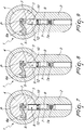
- the ill-intentioned individual will exert a mechanical moment in order to impose a rotation of the rotor 4 clockwise and, subsequently, anticlockwise, by way of such key 6a, in order to cause the oscillation of the pins 8 (as shown in the accompanying Figures 7, 8, 9 ).
- the annular body 13 will always abut with a surface thereof on the rotor 4, making a further lifting of the pin 8 inside the respective channel 7 impossible, and making it effectively impossible to make a perfect impression of the internal encoding components of the lock and therefore to make a perfect copy of the original key 6.
- the present invention solves the above mentioned problems, by providing an anti-intrusion cylinder 1 for locks which is highly secure against methods of cloning the key from the lock alone.
- the present invention makes it possible to provide an anti-intrusion cylinder 1 for locks relatively simply and at substantially low cost: such characteristics ensure a secure practical application of the present invention.
- the materials employed, as well as the dimensions, may be any according to requirements and to the state of the art.
Landscapes
- Lock And Its Accessories (AREA)
Claims (9)
- Ein einbruchverhindernder Zylinder für Schlösser, von der Art, die einen Stator (2) umfasst, der mit einem im Wesentlichen zylindrischen länglichen Hohlraum (3) für die Aufnahme eines Rotors (4) mit einem länglichen Sitz (5) zum Einführen eines Schlüssels (6) ausgestattet ist, wobei der Rotor (4) und der Stator (2) eine Vielzahl von Kanälen (7) umfassen, die im Wesentlichen ausgerichtet und einander zugewandt sind, wenn sich der Zylinder (1) in der geschlossenen Konfiguration befindet; wobei die Kanäle (7) entsprechende Stifte (8), Gegenstifte (9) und optionale elastische Mittel (7a) aufnehmen, die ausgebildet sind, um die Drehung des Rotors (4) im Stator (2) bei Abwesenheit des Schlüssels (6) in dem länglichen Sitz (5) zu verhindern; wobei mindestens einer der Stifte (8) einen Schaft (10) umfasst, wobei der Schaft (10) mit einem pilzförmigen Ende (11) mit einem Durchmesser versehen ist, der kleiner ist als der Durchmesser des Schafts (10), wobei das Ende (11) dem entsprechenden Gegenstift (9) zugewandt ist und an ihn angrenzt; dadurch gekennzeichnet, dass mindestens zwei konturierte ringförmige Körper (13) mit einem Durchmesser, der im Wesentlichen ähnlich dem Durchmesser des Kanals (7) ist, miteinander in einer Säule angeordnet und mit mechanischem Spiel über dem pilzförmigen Ende (11) aufgesetzt sind.
- Der Zylinder gemäß Anspruch 1, dadurch gekennzeichnet, dass das pilzförmige Ende (11) einen Schaft (14) umfasst, der einen ersten Durchmesser mit einem Wert zwischen 1/6 und ¾ des Durchmessers des Kanals (7) hat, überragt von einem Stopfen (15), der einen zweiten Durchmesser mit einem Wert zwischen 1/5 und 5/6 des Durchmessers des Kanals (7) hat.
- Der Zylinder gemäß Anspruch 2, dadurch gekennzeichnet, dass die konturierten ringförmigen Körper (13) eine innere Durchgangsöffnung (16) umfassen, die einen Durchmesser hat, der größer ist als der erste Durchmesser des Schafts (14) und im Wesentlichen komplementär zu dem zweiten Durchmesser des Stopfens (15) ist.
- Der Zylinder gemäß Anspruch 3, dadurch gekennzeichnet, dass die konturierten ringförmigen Körper (13) mit mechanischem Spiel über den Schaft (14) des pilzförmigen Endes (11) aufgesetzt sind und zwischen dem Stopfen (15), unten, und der Endfläche des Schafts (10), oben, angeordnet ist.
- Der Zylinder gemäß einem oder mehreren der obigen Ansprüche, dadurch gekennzeichnet, dass die innere Durchgangsöffnung (16) der konturierten ringförmigen Körper (13) ein erstes Durchgangsloch (17) mit einem Durchmesser umfasst, der komplementär zum Durchmesser des Stopfens (15) ist, und einen äußeren Sitz (18) mit einem Durchmesser, der größer ist als der Durchmesser des Stopfens (15) und ausgebildet, um den Stopfen (15) vorübergehend aufzunehmen.
- Der Zylinder gemäß einem oder mehreren der obigen Ansprüche, dadurch gekennzeichnet, dass der Stift (8) und/oder die konturierten ringförmigen Körper (13) eine äußere Form haben, die vorzugsweise gewählt ist aus zylindrisch, ringförmig, tonnenförmig, kegelstumpfförmig, prismatisch, pyramidenstumpfförmig, tropfenteilförmig und einer Kombination davon.
- Der Zylinder gemäß einem oder mehreren der obigen Ansprüche, dadurch gekennzeichnet, dass die konturierten ringförmigen Körper (13), die miteinander in einer Säule angeordnet sind, identisch miteinander sind.
- Der Zylinder gemäß einem oder mehreren der obigen Ansprüche, dadurch gekennzeichnet, dass die konturierten ringförmigen Körper (13), die miteinander in einer Säule angeordnet sind, verschieden voneinander sind, wobei mindestens ein erster konturierter ringförmiger Körper (13) eine Vertiefung zur partiellen Aufnahme mindestens eines Abschnitts mindestens eines zweiten konturierten ringförmigen Körpers (13) umfasst.
- Der Zylinder gemäß einem oder mehreren der obigen Ansprüche, dadurch gekennzeichnet, dass die Stifte (8), ausgestattet mit dem mindestens einen Schaft (10) mit pilzförmigem Ende (11), das einen kleineren Durchmesser hat als der Schaft (10), und mit mindestens zwei konturierten ringförmigen Körpern (13), die mit mechanischem Spiel über das pilzförmige Ende (11) aufgesetzt sind, mindestens zwei an der Zahl sind, verteilt in verschiedenen Kanälen (7).
Applications Claiming Priority (1)
| Application Number | Priority Date | Filing Date | Title |
|---|---|---|---|
| PCT/IT2016/000173 WO2018011828A1 (en) | 2016-07-11 | 2016-07-11 | Anti-intrusion cylinder for locks |
Publications (2)
| Publication Number | Publication Date |
|---|---|
| EP3482023A1 EP3482023A1 (de) | 2019-05-15 |
| EP3482023B1 true EP3482023B1 (de) | 2020-05-27 |
Family
ID=56997521
Family Applications (1)
| Application Number | Title | Priority Date | Filing Date |
|---|---|---|---|
| EP16770804.9A Active EP3482023B1 (de) | 2016-07-11 | 2016-07-11 | Einbruchverhindernder zylinder für schlösser |
Country Status (4)
| Country | Link |
|---|---|
| EP (1) | EP3482023B1 (de) |
| ES (1) | ES2811920T3 (de) |
| PT (1) | PT3482023T (de) |
| WO (1) | WO2018011828A1 (de) |
Cited By (1)
| Publication number | Priority date | Publication date | Assignee | Title |
|---|---|---|---|---|
| EP4671471A1 (de) * | 2024-06-25 | 2025-12-31 | Securemme S.r.L. | Schliesszylinder und dazugehöriger schlüssel |
Family Cites Families (4)
| Publication number | Priority date | Publication date | Assignee | Title |
|---|---|---|---|---|
| US2111515A (en) * | 1937-03-15 | 1938-03-15 | Herbert H Rauh | Lock |
| US2158501A (en) * | 1938-08-03 | 1939-05-16 | Independent Lock Co | Tumbler lock |
| DE1122866B (de) * | 1960-03-26 | 1962-01-25 | Voss Kg J | Zylinderschloss mit zweiteiligen, abgesetzten Zuhaltungsstiften |
| ITBO20040078A1 (it) * | 2004-02-18 | 2004-05-18 | Cisa Spa | Serratura con organi antimanimissione e relativa chiave |
-
2016
- 2016-07-11 EP EP16770804.9A patent/EP3482023B1/de active Active
- 2016-07-11 WO PCT/IT2016/000173 patent/WO2018011828A1/en not_active Ceased
- 2016-07-11 ES ES16770804T patent/ES2811920T3/es active Active
- 2016-07-11 PT PT167708049T patent/PT3482023T/pt unknown
Non-Patent Citations (1)
| Title |
|---|
| None * |
Cited By (1)
| Publication number | Priority date | Publication date | Assignee | Title |
|---|---|---|---|---|
| EP4671471A1 (de) * | 2024-06-25 | 2025-12-31 | Securemme S.r.L. | Schliesszylinder und dazugehöriger schlüssel |
Also Published As
| Publication number | Publication date |
|---|---|
| WO2018011828A1 (en) | 2018-01-18 |
| ES2811920T3 (es) | 2021-03-15 |
| PT3482023T (pt) | 2020-08-26 |
| EP3482023A1 (de) | 2019-05-15 |
Similar Documents
| Publication | Publication Date | Title |
|---|---|---|
| US3418833A (en) | Tamperproof cylinder lock | |
| US4377940A (en) | Impression-resistant lock | |
| CA2681671C (en) | Hierarchical cylinder lock system | |
| TWI502120B (zh) | 鎖心 | |
| US20200024865A1 (en) | Lockdown cylinder locks | |
| CN106574467A (zh) | 圆柱锁 | |
| EP3482023B1 (de) | Einbruchverhindernder zylinder für schlösser | |
| EP3022371B1 (de) | Einbruchssicherer schlosszylinder | |
| US9353548B2 (en) | Rekeyable cylinder | |
| EP3443186B1 (de) | Einbruchverhindernder zylinder für schlösser | |
| EP3321454B1 (de) | Hochsichere verriegelungsvorrichtung | |
| CN105239836B (zh) | 一种弹子锁 | |
| CN201891299U (zh) | 一种齿条锁珠式空转锁芯 | |
| CN102140867A (zh) | 具有防撬安全特征的挂锁 | |
| CN102864978B (zh) | 锁芯锁定机构 | |
| CA3000930C (en) | Lock and key assembly | |
| CN102080472B (zh) | 一种齿条锁珠式空转锁芯 | |
| CN106032818A (zh) | 防盗螺丝 | |
| CN205400295U (zh) | 一种锁具 | |
| CN1184401C (zh) | 具有多种开闭结构的弹片防盗锁头 | |
| JP4202464B2 (ja) | ディスクタンブラー錠 | |
| CN203430174U (zh) | 改进锁定键的防盗锁头 | |
| CN204152321U (zh) | 一种钥匙锁与密码锁组合的防盗锁 | |
| CN105257101A (zh) | 一种防暴力开启锁具 | |
| CN203462840U (zh) | 一种锁芯与离合芯相结合的锁体 |
Legal Events
| Date | Code | Title | Description |
|---|---|---|---|
| STAA | Information on the status of an ep patent application or granted ep patent |
Free format text: STATUS: THE INTERNATIONAL PUBLICATION HAS BEEN MADE |
|
| PUAI | Public reference made under article 153(3) epc to a published international application that has entered the european phase |
Free format text: ORIGINAL CODE: 0009012 |
|
| STAA | Information on the status of an ep patent application or granted ep patent |
Free format text: STATUS: REQUEST FOR EXAMINATION WAS MADE |
|
| 17P | Request for examination filed |
Effective date: 20190206 |
|
| AK | Designated contracting states |
Kind code of ref document: A1 Designated state(s): AL AT BE BG CH CY CZ DE DK EE ES FI FR GB GR HR HU IE IS IT LI LT LU LV MC MK MT NL NO PL PT RO RS SE SI SK SM TR |
|
| AX | Request for extension of the european patent |
Extension state: BA ME |
|
| DAV | Request for validation of the european patent (deleted) | ||
| DAX | Request for extension of the european patent (deleted) | ||
| GRAP | Despatch of communication of intention to grant a patent |
Free format text: ORIGINAL CODE: EPIDOSNIGR1 |
|
| STAA | Information on the status of an ep patent application or granted ep patent |
Free format text: STATUS: GRANT OF PATENT IS INTENDED |
|
| INTG | Intention to grant announced |
Effective date: 20191209 |
|
| GRAS | Grant fee paid |
Free format text: ORIGINAL CODE: EPIDOSNIGR3 |
|
| GRAA | (expected) grant |
Free format text: ORIGINAL CODE: 0009210 |
|
| STAA | Information on the status of an ep patent application or granted ep patent |
Free format text: STATUS: THE PATENT HAS BEEN GRANTED |
|
| AK | Designated contracting states |
Kind code of ref document: B1 Designated state(s): AL AT BE BG CH CY CZ DE DK EE ES FI FR GB GR HR HU IE IS IT LI LT LU LV MC MK MT NL NO PL PT RO RS SE SI SK SM TR |
|
| REG | Reference to a national code |
Ref country code: GB Ref legal event code: FG4D |
|
| REG | Reference to a national code |
Ref country code: CH Ref legal event code: EP |
|
| REG | Reference to a national code |
Ref country code: AT Ref legal event code: REF Ref document number: 1274701 Country of ref document: AT Kind code of ref document: T Effective date: 20200615 |
|
| REG | Reference to a national code |
Ref country code: DE Ref legal event code: R096 Ref document number: 602016037104 Country of ref document: DE |
|
| REG | Reference to a national code |
Ref country code: PT Ref legal event code: SC4A Ref document number: 3482023 Country of ref document: PT Date of ref document: 20200826 Kind code of ref document: T Free format text: AVAILABILITY OF NATIONAL TRANSLATION Effective date: 20200813 |
|
| REG | Reference to a national code |
Ref country code: LT Ref legal event code: MG4D |
|
| PG25 | Lapsed in a contracting state [announced via postgrant information from national office to epo] |
Ref country code: SE Free format text: LAPSE BECAUSE OF FAILURE TO SUBMIT A TRANSLATION OF THE DESCRIPTION OR TO PAY THE FEE WITHIN THE PRESCRIBED TIME-LIMIT Effective date: 20200527 Ref country code: IS Free format text: LAPSE BECAUSE OF FAILURE TO SUBMIT A TRANSLATION OF THE DESCRIPTION OR TO PAY THE FEE WITHIN THE PRESCRIBED TIME-LIMIT Effective date: 20200927 Ref country code: GR Free format text: LAPSE BECAUSE OF FAILURE TO SUBMIT A TRANSLATION OF THE DESCRIPTION OR TO PAY THE FEE WITHIN THE PRESCRIBED TIME-LIMIT Effective date: 20200828 Ref country code: NO Free format text: LAPSE BECAUSE OF FAILURE TO SUBMIT A TRANSLATION OF THE DESCRIPTION OR TO PAY THE FEE WITHIN THE PRESCRIBED TIME-LIMIT Effective date: 20200827 Ref country code: FI Free format text: LAPSE BECAUSE OF FAILURE TO SUBMIT A TRANSLATION OF THE DESCRIPTION OR TO PAY THE FEE WITHIN THE PRESCRIBED TIME-LIMIT Effective date: 20200527 Ref country code: LT Free format text: LAPSE BECAUSE OF FAILURE TO SUBMIT A TRANSLATION OF THE DESCRIPTION OR TO PAY THE FEE WITHIN THE PRESCRIBED TIME-LIMIT Effective date: 20200527 |
|
| REG | Reference to a national code |
Ref country code: NL Ref legal event code: MP Effective date: 20200527 |
|
| PG25 | Lapsed in a contracting state [announced via postgrant information from national office to epo] |
Ref country code: LV Free format text: LAPSE BECAUSE OF FAILURE TO SUBMIT A TRANSLATION OF THE DESCRIPTION OR TO PAY THE FEE WITHIN THE PRESCRIBED TIME-LIMIT Effective date: 20200527 Ref country code: HR Free format text: LAPSE BECAUSE OF FAILURE TO SUBMIT A TRANSLATION OF THE DESCRIPTION OR TO PAY THE FEE WITHIN THE PRESCRIBED TIME-LIMIT Effective date: 20200527 Ref country code: RS Free format text: LAPSE BECAUSE OF FAILURE TO SUBMIT A TRANSLATION OF THE DESCRIPTION OR TO PAY THE FEE WITHIN THE PRESCRIBED TIME-LIMIT Effective date: 20200527 Ref country code: BG Free format text: LAPSE BECAUSE OF FAILURE TO SUBMIT A TRANSLATION OF THE DESCRIPTION OR TO PAY THE FEE WITHIN THE PRESCRIBED TIME-LIMIT Effective date: 20200827 |
|
| REG | Reference to a national code |
Ref country code: AT Ref legal event code: MK05 Ref document number: 1274701 Country of ref document: AT Kind code of ref document: T Effective date: 20200527 |
|
| PG25 | Lapsed in a contracting state [announced via postgrant information from national office to epo] |
Ref country code: NL Free format text: LAPSE BECAUSE OF FAILURE TO SUBMIT A TRANSLATION OF THE DESCRIPTION OR TO PAY THE FEE WITHIN THE PRESCRIBED TIME-LIMIT Effective date: 20200527 Ref country code: AL Free format text: LAPSE BECAUSE OF FAILURE TO SUBMIT A TRANSLATION OF THE DESCRIPTION OR TO PAY THE FEE WITHIN THE PRESCRIBED TIME-LIMIT Effective date: 20200527 |
|
| PG25 | Lapsed in a contracting state [announced via postgrant information from national office to epo] |
Ref country code: EE Free format text: LAPSE BECAUSE OF FAILURE TO SUBMIT A TRANSLATION OF THE DESCRIPTION OR TO PAY THE FEE WITHIN THE PRESCRIBED TIME-LIMIT Effective date: 20200527 Ref country code: SM Free format text: LAPSE BECAUSE OF FAILURE TO SUBMIT A TRANSLATION OF THE DESCRIPTION OR TO PAY THE FEE WITHIN THE PRESCRIBED TIME-LIMIT Effective date: 20200527 Ref country code: DK Free format text: LAPSE BECAUSE OF FAILURE TO SUBMIT A TRANSLATION OF THE DESCRIPTION OR TO PAY THE FEE WITHIN THE PRESCRIBED TIME-LIMIT Effective date: 20200527 Ref country code: CZ Free format text: LAPSE BECAUSE OF FAILURE TO SUBMIT A TRANSLATION OF THE DESCRIPTION OR TO PAY THE FEE WITHIN THE PRESCRIBED TIME-LIMIT Effective date: 20200527 Ref country code: AT Free format text: LAPSE BECAUSE OF FAILURE TO SUBMIT A TRANSLATION OF THE DESCRIPTION OR TO PAY THE FEE WITHIN THE PRESCRIBED TIME-LIMIT Effective date: 20200527 Ref country code: RO Free format text: LAPSE BECAUSE OF FAILURE TO SUBMIT A TRANSLATION OF THE DESCRIPTION OR TO PAY THE FEE WITHIN THE PRESCRIBED TIME-LIMIT Effective date: 20200527 |
|
| REG | Reference to a national code |
Ref country code: DE Ref legal event code: R119 Ref document number: 602016037104 Country of ref document: DE |
|
| PG25 | Lapsed in a contracting state [announced via postgrant information from national office to epo] |
Ref country code: PL Free format text: LAPSE BECAUSE OF FAILURE TO SUBMIT A TRANSLATION OF THE DESCRIPTION OR TO PAY THE FEE WITHIN THE PRESCRIBED TIME-LIMIT Effective date: 20200527 Ref country code: MC Free format text: LAPSE BECAUSE OF FAILURE TO SUBMIT A TRANSLATION OF THE DESCRIPTION OR TO PAY THE FEE WITHIN THE PRESCRIBED TIME-LIMIT Effective date: 20200527 Ref country code: SK Free format text: LAPSE BECAUSE OF FAILURE TO SUBMIT A TRANSLATION OF THE DESCRIPTION OR TO PAY THE FEE WITHIN THE PRESCRIBED TIME-LIMIT Effective date: 20200527 |
|
| REG | Reference to a national code |
Ref country code: CH Ref legal event code: PL |
|
| REG | Reference to a national code |
Ref country code: ES Ref legal event code: FG2A Ref document number: 2811920 Country of ref document: ES Kind code of ref document: T3 Effective date: 20210315 |
|
| PLBE | No opposition filed within time limit |
Free format text: ORIGINAL CODE: 0009261 |
|
| STAA | Information on the status of an ep patent application or granted ep patent |
Free format text: STATUS: NO OPPOSITION FILED WITHIN TIME LIMIT |
|
| REG | Reference to a national code |
Ref country code: BE Ref legal event code: MM Effective date: 20200731 |
|
| PG25 | Lapsed in a contracting state [announced via postgrant information from national office to epo] |
Ref country code: LU Free format text: LAPSE BECAUSE OF NON-PAYMENT OF DUE FEES Effective date: 20200711 Ref country code: LI Free format text: LAPSE BECAUSE OF NON-PAYMENT OF DUE FEES Effective date: 20200731 Ref country code: CH Free format text: LAPSE BECAUSE OF NON-PAYMENT OF DUE FEES Effective date: 20200731 |
|
| 26N | No opposition filed |
Effective date: 20210302 |
|
| PG25 | Lapsed in a contracting state [announced via postgrant information from national office to epo] |
Ref country code: DE Free format text: LAPSE BECAUSE OF NON-PAYMENT OF DUE FEES Effective date: 20210202 Ref country code: BE Free format text: LAPSE BECAUSE OF NON-PAYMENT OF DUE FEES Effective date: 20200731 Ref country code: SI Free format text: LAPSE BECAUSE OF FAILURE TO SUBMIT A TRANSLATION OF THE DESCRIPTION OR TO PAY THE FEE WITHIN THE PRESCRIBED TIME-LIMIT Effective date: 20200527 |
|
| PG25 | Lapsed in a contracting state [announced via postgrant information from national office to epo] |
Ref country code: IE Free format text: LAPSE BECAUSE OF NON-PAYMENT OF DUE FEES Effective date: 20200711 |
|
| PG25 | Lapsed in a contracting state [announced via postgrant information from national office to epo] |
Ref country code: TR Free format text: LAPSE BECAUSE OF FAILURE TO SUBMIT A TRANSLATION OF THE DESCRIPTION OR TO PAY THE FEE WITHIN THE PRESCRIBED TIME-LIMIT Effective date: 20200527 Ref country code: MT Free format text: LAPSE BECAUSE OF FAILURE TO SUBMIT A TRANSLATION OF THE DESCRIPTION OR TO PAY THE FEE WITHIN THE PRESCRIBED TIME-LIMIT Effective date: 20200527 Ref country code: CY Free format text: LAPSE BECAUSE OF FAILURE TO SUBMIT A TRANSLATION OF THE DESCRIPTION OR TO PAY THE FEE WITHIN THE PRESCRIBED TIME-LIMIT Effective date: 20200527 |
|
| PG25 | Lapsed in a contracting state [announced via postgrant information from national office to epo] |
Ref country code: MK Free format text: LAPSE BECAUSE OF FAILURE TO SUBMIT A TRANSLATION OF THE DESCRIPTION OR TO PAY THE FEE WITHIN THE PRESCRIBED TIME-LIMIT Effective date: 20200527 |
|
| P01 | Opt-out of the competence of the unified patent court (upc) registered |
Effective date: 20230526 |
|
| PGFP | Annual fee paid to national office [announced via postgrant information from national office to epo] |
Ref country code: PT Payment date: 20250626 Year of fee payment: 10 |
|
| PGFP | Annual fee paid to national office [announced via postgrant information from national office to epo] |
Ref country code: ES Payment date: 20250805 Year of fee payment: 10 |
|
| PGFP | Annual fee paid to national office [announced via postgrant information from national office to epo] |
Ref country code: IT Payment date: 20250721 Year of fee payment: 10 |
|
| PGFP | Annual fee paid to national office [announced via postgrant information from national office to epo] |
Ref country code: GB Payment date: 20250710 Year of fee payment: 10 |
|
| PGFP | Annual fee paid to national office [announced via postgrant information from national office to epo] |
Ref country code: FR Payment date: 20250710 Year of fee payment: 10 |