EP3482061B1 - Pompe à carburant à haute pression - Google Patents
Pompe à carburant à haute pression Download PDFInfo
- Publication number
- EP3482061B1 EP3482061B1 EP17824719.3A EP17824719A EP3482061B1 EP 3482061 B1 EP3482061 B1 EP 3482061B1 EP 17824719 A EP17824719 A EP 17824719A EP 3482061 B1 EP3482061 B1 EP 3482061B1
- Authority
- EP
- European Patent Office
- Prior art keywords
- plunger
- pumping
- sealing ring
- fuel
- pressure fuel
- Prior art date
- Legal status (The legal status is an assumption and is not a legal conclusion. Google has not performed a legal analysis and makes no representation as to the accuracy of the status listed.)
- Active
Links
Images

Classifications
-
- F—MECHANICAL ENGINEERING; LIGHTING; HEATING; WEAPONS; BLASTING
- F04—POSITIVE - DISPLACEMENT MACHINES FOR LIQUIDS; PUMPS FOR LIQUIDS OR ELASTIC FLUIDS
- F04B—POSITIVE-DISPLACEMENT MACHINES FOR LIQUIDS; PUMPS
- F04B53/00—Component parts, details or accessories not provided for in, or of interest apart from, groups F04B1/00 - F04B23/00 or F04B39/00 - F04B47/00
- F04B53/14—Pistons, piston-rods or piston-rod connections
- F04B53/143—Sealing provided on the piston
-
- F—MECHANICAL ENGINEERING; LIGHTING; HEATING; WEAPONS; BLASTING
- F02—COMBUSTION ENGINES; HOT-GAS OR COMBUSTION-PRODUCT ENGINE PLANTS
- F02M—SUPPLYING COMBUSTION ENGINES IN GENERAL WITH COMBUSTIBLE MIXTURES OR CONSTITUENTS THEREOF
- F02M59/00—Pumps specially adapted for fuel-injection and not provided for in groups F02M39/00 -F02M57/00, e.g. rotary cylinder-block type of pumps
- F02M59/02—Pumps specially adapted for fuel-injection and not provided for in groups F02M39/00 -F02M57/00, e.g. rotary cylinder-block type of pumps of reciprocating-piston or reciprocating-cylinder type
- F02M59/10—Pumps specially adapted for fuel-injection and not provided for in groups F02M39/00 -F02M57/00, e.g. rotary cylinder-block type of pumps of reciprocating-piston or reciprocating-cylinder type characterised by the piston-drive
- F02M59/102—Mechanical drive, e.g. tappets or cams
-
- F—MECHANICAL ENGINEERING; LIGHTING; HEATING; WEAPONS; BLASTING
- F02—COMBUSTION ENGINES; HOT-GAS OR COMBUSTION-PRODUCT ENGINE PLANTS
- F02M—SUPPLYING COMBUSTION ENGINES IN GENERAL WITH COMBUSTIBLE MIXTURES OR CONSTITUENTS THEREOF
- F02M59/00—Pumps specially adapted for fuel-injection and not provided for in groups F02M39/00 -F02M57/00, e.g. rotary cylinder-block type of pumps
- F02M59/44—Details, components parts, or accessories not provided for in, or of interest apart from, the apparatus of groups F02M59/02 - F02M59/42; Pumps having transducers, e.g. to measure displacement of pump rack or piston
- F02M59/442—Details, components parts, or accessories not provided for in, or of interest apart from, the apparatus of groups F02M59/02 - F02M59/42; Pumps having transducers, e.g. to measure displacement of pump rack or piston means preventing fuel leakage around pump plunger, e.g. fluid barriers
-
- F—MECHANICAL ENGINEERING; LIGHTING; HEATING; WEAPONS; BLASTING
- F04—POSITIVE - DISPLACEMENT MACHINES FOR LIQUIDS; PUMPS FOR LIQUIDS OR ELASTIC FLUIDS
- F04B—POSITIVE-DISPLACEMENT MACHINES FOR LIQUIDS; PUMPS
- F04B1/00—Multi-cylinder machines or pumps characterised by number or arrangement of cylinders
- F04B1/04—Multi-cylinder machines or pumps characterised by number or arrangement of cylinders having cylinders in star- or fan-arrangement
- F04B1/0404—Details or component parts
- F04B1/0408—Pistons
-
- F—MECHANICAL ENGINEERING; LIGHTING; HEATING; WEAPONS; BLASTING
- F04—POSITIVE - DISPLACEMENT MACHINES FOR LIQUIDS; PUMPS FOR LIQUIDS OR ELASTIC FLUIDS
- F04B—POSITIVE-DISPLACEMENT MACHINES FOR LIQUIDS; PUMPS
- F04B1/00—Multi-cylinder machines or pumps characterised by number or arrangement of cylinders
- F04B1/04—Multi-cylinder machines or pumps characterised by number or arrangement of cylinders having cylinders in star- or fan-arrangement
- F04B1/0404—Details or component parts
- F04B1/0448—Sealing means, e.g. for shafts or housings
-
- F—MECHANICAL ENGINEERING; LIGHTING; HEATING; WEAPONS; BLASTING
- F04—POSITIVE - DISPLACEMENT MACHINES FOR LIQUIDS; PUMPS FOR LIQUIDS OR ELASTIC FLUIDS
- F04B—POSITIVE-DISPLACEMENT MACHINES FOR LIQUIDS; PUMPS
- F04B1/00—Multi-cylinder machines or pumps characterised by number or arrangement of cylinders
- F04B1/04—Multi-cylinder machines or pumps characterised by number or arrangement of cylinders having cylinders in star- or fan-arrangement
- F04B1/053—Multi-cylinder machines or pumps characterised by number or arrangement of cylinders having cylinders in star- or fan-arrangement with actuating or actuated elements at the inner ends of the cylinders
-
- F—MECHANICAL ENGINEERING; LIGHTING; HEATING; WEAPONS; BLASTING
- F04—POSITIVE - DISPLACEMENT MACHINES FOR LIQUIDS; PUMPS FOR LIQUIDS OR ELASTIC FLUIDS
- F04B—POSITIVE-DISPLACEMENT MACHINES FOR LIQUIDS; PUMPS
- F04B19/00—Machines or pumps having pertinent characteristics not provided for in, or of interest apart from, groups F04B1/00 - F04B17/00
- F04B19/20—Other positive-displacement pumps
- F04B19/22—Other positive-displacement pumps of reciprocating-piston type
-
- F—MECHANICAL ENGINEERING; LIGHTING; HEATING; WEAPONS; BLASTING
- F04—POSITIVE - DISPLACEMENT MACHINES FOR LIQUIDS; PUMPS FOR LIQUIDS OR ELASTIC FLUIDS
- F04B—POSITIVE-DISPLACEMENT MACHINES FOR LIQUIDS; PUMPS
- F04B53/00—Component parts, details or accessories not provided for in, or of interest apart from, groups F04B1/00 - F04B23/00 or F04B39/00 - F04B47/00
- F04B53/02—Packing the free space between cylinders and pistons
-
- F—MECHANICAL ENGINEERING; LIGHTING; HEATING; WEAPONS; BLASTING
- F04—POSITIVE - DISPLACEMENT MACHINES FOR LIQUIDS; PUMPS FOR LIQUIDS OR ELASTIC FLUIDS
- F04B—POSITIVE-DISPLACEMENT MACHINES FOR LIQUIDS; PUMPS
- F04B53/00—Component parts, details or accessories not provided for in, or of interest apart from, groups F04B1/00 - F04B23/00 or F04B39/00 - F04B47/00
- F04B53/14—Pistons, piston-rods or piston-rod connections
-
- F—MECHANICAL ENGINEERING; LIGHTING; HEATING; WEAPONS; BLASTING
- F04—POSITIVE - DISPLACEMENT MACHINES FOR LIQUIDS; PUMPS FOR LIQUIDS OR ELASTIC FLUIDS
- F04B—POSITIVE-DISPLACEMENT MACHINES FOR LIQUIDS; PUMPS
- F04B53/00—Component parts, details or accessories not provided for in, or of interest apart from, groups F04B1/00 - F04B23/00 or F04B39/00 - F04B47/00
- F04B53/16—Casings; Cylinders; Cylinder liners or heads; Fluid connections
-
- F—MECHANICAL ENGINEERING; LIGHTING; HEATING; WEAPONS; BLASTING
- F04—POSITIVE - DISPLACEMENT MACHINES FOR LIQUIDS; PUMPS FOR LIQUIDS OR ELASTIC FLUIDS
- F04B—POSITIVE-DISPLACEMENT MACHINES FOR LIQUIDS; PUMPS
- F04B7/00—Piston machines or pumps characterised by having positively-driven valving
- F04B7/0076—Piston machines or pumps characterised by having positively-driven valving the members being actuated by electro-magnetic means
-
- F—MECHANICAL ENGINEERING; LIGHTING; HEATING; WEAPONS; BLASTING
- F02—COMBUSTION ENGINES; HOT-GAS OR COMBUSTION-PRODUCT ENGINE PLANTS
- F02M—SUPPLYING COMBUSTION ENGINES IN GENERAL WITH COMBUSTIBLE MIXTURES OR CONSTITUENTS THEREOF
- F02M2200/00—Details of fuel-injection apparatus, not otherwise provided for
- F02M2200/16—Sealing of fuel injection apparatus not otherwise provided for
Definitions
- the present invention relates to a fuel pump, more particularly to a high-pressure fuel pump which provides fuel at high-pressure for injection directly into a combustion chamber of an internal combustion engine, even more particularly to such a fuel pump having a pumping plunger which reciprocates within a plunger bore of a pump housing to pressurize fuel within a pumping chamber defined in the pump housing, and still even more particularly to such a fuel pump in which the pumping plunger includes an annular sealing ring groove and a sealing ring within the sealing ring groove which engages the plunger bore in an interference fit to prevent fuel from escaping the pumping chamber between the interface of the pumping plunger and the plunger bore.
- Fuel systems for modern internal combustion engines typically employ either 1) port fuel injection (PFI) where fuel is injected into an air intake manifold of the internal combustion engine at relatively low pressure (typically below about 500 kPa) and subsequently passed to the combustion chamber of the internal combustion engine or 2) gasoline direct injection (GDi) where fuel is injected directly into the combustion chamber of the internal combustion engine at relatively high pressure (typically above about 14 MPa).
- PFI port fuel injection
- GDi gasoline direct injection
- the fuel is typically pumped from a fuel tank to the internal combustion engine by an electric fuel pump which is located with the fuel tank of the fuel system.
- GDi systems require an additional fuel pump to boost the pressure of the fuel compared to the pressure which can be achieved by the electric fuel pump.
- a piston-type high-pressure fuel pump which is driven by a camshaft of the internal combustion engine.
- a pump housing defines an inlet, an outlet, a pumping chamber, and a plunger bore which opens into the pumping chamber.
- a pumping plunger is reciprocated within the plunger bore by a camshaft of the internal combustion engine such that each cycle of the pumping plunger increases and decreases the volume of the pumping chamber.
- An inlet valve selectively opens when the pumping plunger is moving in a direction which increases the volume of the pumping chamber, i.e. the inlet stroke, thereby allowing low-pressure fuel to enter the pumping chamber.
- the pumping plunger is moving in a direction which decreases the volume of the pumping chamber, i.e.
- the clearance between the pumping plunger and the plunger bore not be too small because there is a risk that the pumping plunger could seize within the plunger bore during operation due to heat generated by operation of the high-pressure pump causing the pumping plunger to expand radially outward to a greater extent than the plunger bore expands, due to poor lubrication as a result of insufficient clearance for fuel between the pumping plunger and the plunger bore, and due to side load effects on the pumping plunger.
- a clearance of 11 microns plus or minus 1 micron may be a typical acceptable tolerance in the manufacture of the pumping plunger and the plunger bore.
- Such a tolerance is costly to implement and may require match honing between the pumping plunger and the plunger bore, thereby adding time and complexity to the manufacturing process. Furthermore, such a tolerance may require that the pump be increased in fuel pumping capacity to accommodate the low efficiency that is experienced, particularly at low-speed operation of the internal combustion engine.
- a high-pressure fuel pump includes a pump housing which defines a pumping chamber, a fuel inlet which allows low-pressure fuel into the pumping chamber, a fuel outlet which allows high-pressure fuel out of the pumping chamber, and a plunger bore which extends along an axis and opens into the pumping chamber.
- the high-pressure fuel pump also includes a pumping plunger which reciprocates within the plunger bore along the axis such that reciprocation of the pumping plunger within the plunger bore increases and decreases a volume of the pumping chamber. Low-pressure fuel flows from the fuel inlet to the pumping chamber when the volume increases and high-pressure fuel is discharged from the pumping chamber through the fuel outlet when the volume decreases.
- the pumping plunger is attached to a cam follower which contacts a cam shaft, in use, to drive reciprocating movement of the pumping plunger, and wherein a return spring is compressed axially between the pump housing and the cam follower to maintain the cam follower in contact with the camshaft, in use.
- the pumping plunger includes a sealing ring groove, therein, for preventing fuel from escaping the pumping chamber between the interface of the pumping plunger and plunger bore, wherein the sealing ring engages said plunger bore in an interference fit, such that said sealing ring is held in radial compression by said pumping plunger and said plunger bore and wherein said sealing ring is held in axial compression within said sealing ring groove.
- a diametric clearance in the range of 13 to 30 microns is provided between the pumping plunger and the plunger bore.
- the pumping plunger may also include: a second sealing ring groove which may be concentric with plunger bore, the second sealing ring groove including a second sealing ring, which may engage the plunger bore in an interference fit.
- the sealing ring groove may be annular.
- the sealing ring may be annular.
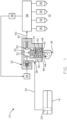
- Fuel system 10 generally includes a fuel tank 14 which holds a volume of fuel to be supplied to internal combustion engine 12 for operation thereof; a plurality of high-pressure fuel injectors 16 which inject fuel directly into respective combustion chambers (not shown) of internal combustion engine 12; a low-pressure fuel pump 20; and a high-pressure fuel pump 22 where the low-pressure fuel pump 20 draws fuel from fuel tank 14 and elevates the pressure of the fuel for delivery to high-pressure fuel pump 22 where the high-pressure fuel pump 22 further elevates the pressure of the fuel for delivery to high-pressure fuel injectors 16.
- low-pressure fuel pump 20 may elevate the pressure of the fuel to about 500 kPa or less and high-pressure fuel pump 22 may elevate the pressure of the fuel to above about 14 MPa where pressures on the order of 40 MPa and above are anticipated. While four high-pressure fuel injectors 16 have been illustrated, it should be understood that a lesser or greater number of high-pressure fuel injectors 16 may be provided. As shown, low-pressure fuel pump 20 may be provided within fuel tank 14, however low-pressure fuel pump 20 may alternatively be provided outside of fuel tank 14. Low-pressure fuel pump 20 may be an electric fuel pump. A low-pressure fuel supply passage 24 provides fluid communication from low-pressure fuel pump 20 to high-pressure fuel pump 22. High-pressure fuel pump 22 will be described in greater detail in the paragraphs that follow.
- High-pressure fuel pump 22 includes a pump housing 30 which defines a pumping chamber 32 and a plunger bore 34 which opens into pumping chamber 32 such that plunger bore 34 extends along an axis 36.
- Pump housing 30 also includes a fuel inlet 38 in fluid communication with low-pressure fuel supply passage 24 such that fuel inlet 38 selectively allows low-pressure fuel from low-pressure fuel pump 20 to enter pumping chamber 32 as will be described in greater detail later.
- Pump housing 30 also defines a fuel outlet 40 which selectively allows high-pressure fuel to exit pumping chamber 32 as will be described in greater detail later. While pump housing 30 has been illustrated schematically as single-piece construction, it should be understood that pump housing 30 may comprise two or more pieces which are joined together to provide the features described herein.
- High-pressure fuel pump 22 also includes a pumping plunger 42 located within plunger bore 34 such that pumping plunger 42 reciprocates within plunger bore 34 along axis 36.
- Pumping plunger 42 is reciprocated within plunger bore 34, by way of non-limiting example only, by a camshaft 44 of internal combustion engine 12.
- Pumping plunger 42 is attached to (in contact with) a cam follower 46 which follows the profile of camshaft 44.
- Cam follower 46 is axially guided within a cam follower bore 48 of pump housing 30 such that a return spring 50 is compressed axially between pump housing 30 and cam follower 46 to maintain cam follower 46 in contact with camshaft 44 as camshaft 44 rotates.
- cam follower 46 has been embodied as being guided within cam follower bore 48 of pump housing 30, it should now be understood that cam follower 46 may alternatively be guided within a bore of internal combustion engine 12 that is not within pump housing 30.
- camshaft 44, cam follower 46, and return spring 50 cause pumping plunger 42 to move downward as viewed in the figures, the volume of pumping chamber 32 is increased, thereby resulting in an inlet stroke.
- camshaft 44 and cam follower 46 cause pumping plunger 42 to move upward as viewed in the figures, the volume of pumping chamber 32 is decreased, thereby resulting in a pressure stroke.
- a low-pressure seal may be provided to prevent fuel, that has leaked past the clearance between pumping plunger 42 and plunger bore 34, from mixing with oil that lubricates internal combustion engine 12.
- a low-pressure seal is illustrated by Nakayama et al. which was previously referenced above.
- High-pressure fuel pump 22 also includes an inlet valve 52 which selectively opens to permit fuel to enter pumping chamber 32 from low-pressure fuel supply passage 24.
- Inlet valve 52 may be, by way of non-limiting example only, a solenoid operated valve which is controlled by a controller 54.
- Controller 54 may receive input from a pressure sensor 56 which supplies a signal indicative of the pressure of the fuel being supplied to high-pressure fuel injectors 16.
- a pressure sensor 56 may arranged to read the fuel pressure within a high-pressure fuel rail 58 which receives high-pressure fuel from fuel outlet 40 through a high-pressure fuel supply passage 60 such that high-pressure fuel rail 58 distributes high-pressure fuel to each of high-pressure fuel injectors 16.
- pressure sensor 56 may be positioned at other locations that are indicative of the pressure of the fuel being supplied to high-pressure fuel injectors 16.
- Controller 54 sends signals to inlet valve 52 to open and close inlet valve 52 as necessary to achieve a desired fuel pressure at pressure sensor 56 as may be determined by current and anticipated engine operating demands.
- inlet valve 52 is opened while pumping plunger 42 is moving to increase the volume of pumping chamber 32, i.e. when inlet valve 52 is moving downward as viewed in the figures, fuel from low-pressure fuel supply passage 24 is allowed to flow into pumping chamber 32 through fuel inlet 38.
- High-pressure fuel pump 22 also includes an outlet valve 62 which selectively opens to permit fuel to exit pumping chamber 32 to high-pressure fuel supply passage 60.
- Outlet valve 62 may be a spring-biased valve which opens when the pressure differential between pumping chamber 32 and high-pressure fuel supply passage 60 is greater than a predetermined threshold. Consequently, when camshaft 44 and cam follower 46 cause pumping plunger 42 to decrease the volume of pumping chamber 32, the fuel within pumping chamber 32 is pressurized. Furthermore, when the pressure within pumping chamber 32 is sufficiently high, outlet valve 62 is urged open by the fuel pressure, thereby causing pressurized fuel to be supplied to high-pressure fuel injectors 16 through fuel outlet 40, high-pressure fuel supply passage 60, and high-pressure fuel rail 58.
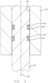
- Fig. 2 shows an enlarged portion of Fig. 1 , more particularly, an enlarged portion showing portions of pump housing 30 and pumping plunger 42.
- pumping plunger 42 which is cylindrical, is provided with a sealing ring groove 64 within which is located a sealing ring 66. Sealing ring groove 64 is annular in shape and concentric with pumping plunger 42 and plunger bore 34 such that sealing ring groove 64 extends radially inward from the outer periphery of pumping plunger 42.
- Sealing ring 66 is preferably made of PTFE (polytetrafluoroethylene) due to low friction and fuel resistant properties, however, other materials may be substituted.
- sealing ring 66 is elastically stretched over pumping plunger 42 and slid on the outer periphery of pumping plunger 42 until sealing ring 66 is aligned with sealing ring groove 64. After sealing ring 66 is aligned with sealing ring groove 64, sealing ring 66 retracts into sealing ring groove 64. Sealing ring 66 is sized to engage plunger bore 34 in an interference fit.
- sealing ring 66 engages plunger bore 34 in an interference fit, the diametric clearance between pumping plunger 42 and plunger bore 34 can be greater than 12 microns, thereby eliminating the need to match hone pumping plunger 42 and plunger bore 34.
- the diametric clearance between pumping plunger 42 and plunger bore 34 is in the range of 13 microns to 30 microns.
- sealing ring 66 engaging plunger bore 34 in an interference fit increases the efficiency of high-pressure fuel pump 22, particularly at low rotational rates of camshaft 44, by minimizing fuel leakage between pumping plunger 42 and plunger bore 34.
- Sealing ring 66 is also sized such that when pumping plunger 42 with sealing ring 66 is installed within plunger bore 34, sealing ring 66 is held in radial compression between plunger bore 34 and pumping plunger 42. Furthermore, the radial compression of sealing ring 66 by plunger bore 34 and pumping plunger 42 causes sealing ring 66 to expand axially such that sealing ring 66 is held in axial compression between the upper and lower walls (as oriented in the figures) of sealing ring groove 64.
- pumping plunger 42 including sealing ring 66 Another added benefit of pumping plunger 42 including sealing ring 66 is that the risk of pumping plunger 42 seizing within plunger bore 34 is minimized because the clearance between pumping plunger 42 and plunger bore 34 can be increased to an extent such that thermal expansion of pumping plunger 42 in use will not be sufficient to bind pumping plunger 42 within plunger bore 34.
- Nakayama et al. which was introduced above in the Background of Invention section, discloses a seal system, identified by reference number 21 in Nakayama et al., which maintains separation between gasoline and engine oil.
- the seal system of Nakayama et al. unlike sealing ring 66 of the present invention, does nothing to improve the efficiency of the fuel pump because the seal system of Nakayama et al. is on the low-pressure side of the interface of the pumping plunger and the plunger bore. Consequently, the efficiency of the fuel pump of Nakayama et al. is dependent upon the clearance between the pumping plunger and the plunger bore.
- inlet valve 52 In operation, during the inlet stroke, inlet valve 52 is opened to allow fuel to flow into pumping chamber 32 from fuel inlet 38 as pumping plunger 42 is increasing the volume of pumping chamber 32 as a result of camshaft 44 and return spring 50. Inlet valve 52 may remain open during the inlet stroke for a period of time, determined by controller 54, which is sufficient to allow a volume of fuel into pumping chamber 32 that will satisfy the fueling needs of internal combustion engine 12. During the pressure stroke, when inlet valve 52 is closed, pumping plunger 42 decreases the volume of pumping chamber 32 as a result of camshaft 44.
- pumping plunger 42 may include two sealing ring grooves 64 such that each sealing ring groove contains a respective sealing ring 66 which engages plunger bore 34 and pumping plunger 42 in the same manner described earlier with respect to Fig. 2 . It should now be understood that additional sealing ring grooves 64 and sealing rings 66 may also be included.
- sealing ring groove 64 and sealing ring 66 provides for greater efficiency of high-pressure fuel pump 22.
- inclusion of sealing ring groove 64 and sealing ring 66 provided increased efficiency at all operational speeds of the high-pressure fuel pumps, with a particularly significant increase in efficiency at lower operating speeds. This increase in efficiency may allow for high-pressure fuel pump 22 to be downsized in fuel pumping capacity, thereby reducing the cost of high-pressure fuel pump 22, since high-pressure fuel pump 22 does not need to accommodate a loss in efficiency, particularly at low operational speeds of internal combustion engine 12.
- Downsizing the fuel pumping capacity of high-pressure fuel pump 22, for example by decreasing the diameter of pumping plunger 42, is important because emission regulation are continually being made more stringent and the desire to provide fuel at higher pressure is more desirable to better atomize the fuel which is beneficial for reducing emissions of internal combustion engine 12. Decreasing the diameter of pumping plunger 42 is a way to limit excessive loads on the valve train of internal combustion engine 12, but this can only be done if the efficiency of high-pressure fuel pump 22 is improved at higher pressures.
- a further benefit of sealing ring groove 64 and sealing ring 66 is that the clearance between pumping plunger 42 and plunger bore 34 is able to be increased, thereby eliminating the need for time consuming and costly manufacturing techniques such as match honing of pumping plunger 42 and plunger bore 34.
Landscapes
- Engineering & Computer Science (AREA)
- Mechanical Engineering (AREA)
- General Engineering & Computer Science (AREA)
- Chemical & Material Sciences (AREA)
- Combustion & Propulsion (AREA)
- Fuel-Injection Apparatus (AREA)
Claims (4)
- Pompe à carburant haute pression (22) pour l'injection directe d'essence et comprenant :un corps de pompe (30) qui définit une chambre de pompage (32), une entrée de carburant (38) par laquelle du carburant à faible pression peut entrer dans ladite chambre de pompage (32), une sortie de carburant (40) par laquelle du carburant à pression élevée peut sortir de ladite chambre de pompage (32), et un orifice à piston (34) qui s'étend le long d'un axe (36) et débouche dans ladite chambre de pompage (32) ; etun piston de pompage (42) qui se déplace en va-et-vient à l'intérieur dudit orifice à piston (34) le long dudit axe (36) de telle sorte que le va-et-vient dudit piston de pompage (42) à l'intérieur dudit orifice à piston (34) augmente et diminue un volume de ladite chambre de pompage (32), de telle sorte que du carburant à faible pression s'écoule depuis ladite entrée de carburant (38) vers ladite chambre de pompage (32) lorsque ledit volume augmente, et du carburant à pression élevée soit rejeté hors de ladite chambre de pompage (32) à travers ladite sortie de carburant (40) lorsque ledit volume diminue ;dans laquelle le piston de pompage (42) est attaché à un suiveur de came (46) qui peut être mis en contact avec un arbre à cames (44), conçu pour entraîner un déplacement en va-et-vient du piston de pompage (42), et dans laquelle un ressort de rappel (50) est comprimé axialement entre le corps de pompe (30) et le suiveur de came (46) afin de maintenir le suiveur de came (46) en contact avec l'arbre à cames (44), pendant l'utilisation,dans laquelle ledit piston de pompage (42) comprend une gorge à bague d'étanchéité (64) qui est concentrique relativement audit orifice à piston (34), une bague d'étanchéité (66) étant placée dans ladite gorge à bague d'étanchéité (64), pour empêcher que du carburant ne s'échappe de la chambre de pompage (32) entre l'interface du piston de pompage (42) et de l'orifice à piston (34), dans laquelle la bague d'étanchéité (66) entre en prise avec ledit orifice à piston (34) avec un ajustement serré, de telle sorte que ladite bague d'étanchéité (66) soit maintenue en compression radiale par ledit piston de pompage (42) et ledit orifice à piston (34) ;et dans laquelle ladite bague d'étanchéité (66) est maintenue en compression axiale à l'intérieur de ladite gorge à bague d'étanchéité (64) ; etdans laquelle un jeu diamétral compris entre 13 et 30 micromètres est défini entre ledit piston de pompage (42) et ledit orifice à piston (34).
- Pompe à carburant haute pression (22) selon la revendication 1, dans laquelle ledit piston de pompage (42) comprend également :
une seconde gorge à bague d'étanchéité (64) qui est concentrique relativement audit orifice à piston (34), une seconde bague d'étanchéité (66) étant placée dans ladite seconde gorge à bague d'étanchéité (64), celle-ci entrant en prise avec ledit orifice à piston (34) avec un ajustement serré. - Pompe à carburant haute pression (22) selon la revendication 1 ou 2, dans laquelle ladite gorge à bague d'étanchéité (64) est annulaire.
- Pompe à carburant haute pression (22) selon la revendication 3, dans laquelle ladite bague d'étanchéité (66) est annulaire.
Applications Claiming Priority (2)
| Application Number | Priority Date | Filing Date | Title |
|---|---|---|---|
| US15/205,349 US20180010600A1 (en) | 2016-07-08 | 2016-07-08 | High-pressure fuel pump |
| PCT/US2017/039706 WO2018009390A1 (fr) | 2016-07-08 | 2017-06-28 | Pompe à carburant à haute pression |
Publications (3)
| Publication Number | Publication Date |
|---|---|
| EP3482061A1 EP3482061A1 (fr) | 2019-05-15 |
| EP3482061A4 EP3482061A4 (fr) | 2020-02-19 |
| EP3482061B1 true EP3482061B1 (fr) | 2025-06-11 |
Family
ID=60893277
Family Applications (1)
| Application Number | Title | Priority Date | Filing Date |
|---|---|---|---|
| EP17824719.3A Active EP3482061B1 (fr) | 2016-07-08 | 2017-06-28 | Pompe à carburant à haute pression |
Country Status (6)
| Country | Link |
|---|---|
| US (2) | US20180010600A1 (fr) |
| EP (1) | EP3482061B1 (fr) |
| KR (2) | KR20190010716A (fr) |
| CN (2) | CN109563798A (fr) |
| GB (1) | GB2625958B (fr) |
| WO (1) | WO2018009390A1 (fr) |
Families Citing this family (9)
| Publication number | Priority date | Publication date | Assignee | Title |
|---|---|---|---|---|
| DE102016209930A1 (de) | 2016-06-06 | 2017-12-07 | Elringklinger Ag | Kolbenvorrichtung und Pumpenvorrichtung |
| EP3980646B1 (fr) | 2019-05-30 | 2025-05-07 | Motor Components LLC | Pompe à carburant |
| IT202000017767A1 (it) * | 2020-07-22 | 2022-01-22 | Marelli Europe Spa | Pompa carburante per un sistema di iniezione diretta |
| CN114592995A (zh) * | 2020-11-20 | 2022-06-07 | 康明斯公司 | 燃料泵设备、系统和方法 |
| DE102021214501A1 (de) | 2021-12-16 | 2023-06-22 | Robert Bosch Gesellschaft mit beschränkter Haftung | Hochdruckpumpe für ein Kraftstoffsystem einer Brennkraftmaschine |
| GB2638279A (en) | 2024-02-19 | 2025-08-20 | Phinia Delphi Luxembourg Sarl | Fuel pump and plunger arrangement therefor |
| GB2638278A (en) | 2024-02-19 | 2025-08-20 | Phinia Delphi Luxembourg Sarl | Fuel pump and sealing arrangement therefor |
| GB2638277A (en) * | 2024-02-19 | 2025-08-20 | Phinia Delphi Luxembourg Sarl | Fuel pump and seal arrangement therefor |
| GB2644232A (en) | 2024-09-24 | 2026-03-25 | Phinia Delphi Luxembourg Sarl | Fuel pump and sealing arrangement |
Citations (2)
| Publication number | Priority date | Publication date | Assignee | Title |
|---|---|---|---|---|
| US5682861A (en) * | 1996-05-23 | 1997-11-04 | Caterpillar Inc. | Fluid seal for cyclic high pressures within a fuel injection |
| JPH1082353A (ja) * | 1996-09-09 | 1998-03-31 | Hitachi Ltd | 燃料ポンプ |
Family Cites Families (32)
| Publication number | Priority date | Publication date | Assignee | Title |
|---|---|---|---|---|
| US2282562A (en) * | 1939-11-07 | 1942-05-12 | Wheeler J Cole | Diesel engine fuel pump |
| US2569233A (en) | 1947-09-17 | 1951-09-25 | Gen Motors Corp | Fuel injection pump |
| US3145629A (en) | 1960-12-13 | 1964-08-25 | Union Carbide Corp | Cryogenic pump sealing rings |
| US3212785A (en) * | 1964-01-13 | 1965-10-19 | Muskegon Piston Ring Co Inc | Oil ring |
| US4050360A (en) * | 1975-09-19 | 1977-09-27 | Caterpillar Tractor Co. | Oil damped piston |
| DE19522306B4 (de) * | 1994-06-24 | 2004-08-26 | Denso Corp., Kariya | Hochdruck-Kraftstoffzuführungspumpe |
| US5996472A (en) * | 1996-10-07 | 1999-12-07 | Chemical Seal And Packing, Inc. | Cryogenic reciprocating pump |
| EP0903490B1 (fr) * | 1997-03-25 | 2003-09-24 | Isuzu Motors Limited | Injecteur |
| US5992768A (en) | 1997-12-08 | 1999-11-30 | Caterpillar Inc. | Fluid seal for cyclic high pressures within a fuel injector |
| IT1306319B1 (it) * | 1998-07-16 | 2001-06-04 | Magneti Marelli Spa | Gruppo di alimentazione di carburante ad un motore endotermico |
| JP2003206825A (ja) * | 2002-01-16 | 2003-07-25 | Denso Corp | 代替燃料用の高圧ポンプ |
| US7150606B2 (en) | 2003-10-28 | 2006-12-19 | Motor Components Llc | Electromagnetic fuel pump |
| JP2005133681A (ja) | 2003-10-31 | 2005-05-26 | Nok Corp | 往復動部材の密封構造 |
| US7100577B2 (en) * | 2004-06-14 | 2006-09-05 | Westport Research Inc. | Common rail directly actuated fuel injection valve with a pressurized hydraulic transmission device and a method of operating same |
| US8011289B2 (en) * | 2006-01-13 | 2011-09-06 | Bwi Company Limited S.A. | Half-sleeved and sleeveless plastic piston pumps |
| JP4414966B2 (ja) | 2006-01-16 | 2010-02-17 | Nok株式会社 | 高圧燃料ポンプおよび高圧燃料ポンプ用シールシステム |
| EP2129869B1 (fr) * | 2007-03-16 | 2015-01-28 | Cummins Inc. | Ensemble piston à faible fuite destiné à un système de fluide à haute pression |
| DE102007057840A1 (de) * | 2007-11-30 | 2009-06-04 | Ks Kolbenschmidt Gmbh | Funktionsoptimierte Gestaltung des Kolben-Ringfeldbereiches bei Stahlkolben |
| DE102008010242A1 (de) * | 2008-02-21 | 2009-08-27 | Robert Bosch Gmbh | Hochdruckerzeuger für Einspritzanlagen von Brennkraftmaschinen |
| DE102008010286A1 (de) | 2008-02-21 | 2009-08-27 | Robert Bosch Gmbh | Kolbenpumpe |
| DE102009028609A1 (de) | 2009-08-18 | 2011-02-24 | Robert Bosch Gmbh | Manuell betätigbare Pumpenvorrichtung |
| JP5372692B2 (ja) * | 2009-10-06 | 2013-12-18 | 日立オートモティブシステムズ株式会社 | 高圧燃料ポンプ |
| EP2339166A1 (fr) * | 2009-12-23 | 2011-06-29 | Caterpillar Motoren GmbH & Co. KG | Procédé de purge et système avec racleur ou anneau racleur pour empêcher la formation de dépôts dans une pompe à carburant |
| JP5401360B2 (ja) | 2010-02-26 | 2014-01-29 | 日立オートモティブシステムズ株式会社 | 高圧燃料供給ポンプ |
| EP2678588B1 (fr) * | 2011-02-25 | 2021-05-05 | Neo Mechanics Limited | Pompe à piston axial pourvue de pistons dotés de bagues d'étanchéité métalliques |
| CN102359446A (zh) * | 2011-09-14 | 2012-02-22 | 大连金地机电工程有限公司 | 一种柱塞泵密封结构 |
| CN202883354U (zh) * | 2012-10-22 | 2013-04-17 | 吴玲媛 | 一种高压柱塞泵密封结构 |
| DE102013217357A1 (de) | 2013-08-30 | 2015-03-05 | Robert Bosch Gmbh | Pumpe, insbesondere eine Kraftstoffhochdruckpumpe |
| JP6224415B2 (ja) | 2013-10-29 | 2017-11-01 | 日立オートモティブシステムズ株式会社 | 高圧燃料供給ポンプ |
| GB201402535D0 (en) * | 2014-02-13 | 2014-04-02 | Delphi Int Operations Luxembourg Sarl | Fuel pump |
| DE102015120039A1 (de) * | 2015-11-19 | 2017-05-24 | L'orange Gmbh | Hochdruckpumpe, insbesondere zur Kraftstoffeinspritzung |
| IT202000017767A1 (it) | 2020-07-22 | 2022-01-22 | Marelli Europe Spa | Pompa carburante per un sistema di iniezione diretta |
-
2016
- 2016-07-08 US US15/205,349 patent/US20180010600A1/en not_active Abandoned
-
2017
- 2017-06-28 CN CN201780042285.7A patent/CN109563798A/zh active Pending
- 2017-06-28 KR KR1020197001490A patent/KR20190010716A/ko not_active Ceased
- 2017-06-28 WO PCT/US2017/039706 patent/WO2018009390A1/fr not_active Ceased
- 2017-06-28 EP EP17824719.3A patent/EP3482061B1/fr active Active
-
2021
- 2021-09-17 US US17/477,737 patent/US11713755B2/en active Active
-
2022
- 2022-09-14 KR KR1020247012475A patent/KR20240058173A/ko active Pending
- 2022-09-14 GB GB2405062.7A patent/GB2625958B/en active Active
- 2022-09-14 CN CN202280062391.2A patent/CN117980600A/zh active Pending
Patent Citations (2)
| Publication number | Priority date | Publication date | Assignee | Title |
|---|---|---|---|---|
| US5682861A (en) * | 1996-05-23 | 1997-11-04 | Caterpillar Inc. | Fluid seal for cyclic high pressures within a fuel injection |
| JPH1082353A (ja) * | 1996-09-09 | 1998-03-31 | Hitachi Ltd | 燃料ポンプ |
Also Published As
| Publication number | Publication date |
|---|---|
| US20180010600A1 (en) | 2018-01-11 |
| KR20240058173A (ko) | 2024-05-03 |
| EP3482061A1 (fr) | 2019-05-15 |
| GB2625958A (en) | 2024-07-03 |
| WO2018009390A1 (fr) | 2018-01-11 |
| US20220003233A1 (en) | 2022-01-06 |
| CN117980600A (zh) | 2024-05-03 |
| GB2625958B (en) | 2026-03-25 |
| KR20190010716A (ko) | 2019-01-30 |
| EP3482061A4 (fr) | 2020-02-19 |
| CN109563798A (zh) | 2019-04-02 |
| US11713755B2 (en) | 2023-08-01 |
Similar Documents
| Publication | Publication Date | Title |
|---|---|---|
| EP3482061B1 (fr) | Pompe à carburant à haute pression | |
| EP1707799B1 (fr) | Pompe de carburant à plongeur et système d'alimentation en carburant utilisant la même | |
| US9091255B2 (en) | Fuel supply pump | |
| EP2915995B1 (fr) | Pompe d'alimentation en combustible haute pression | |
| JPH0868370A (ja) | 高圧燃料供給ポンプ | |
| CN104053897A (zh) | 用于燃料喷射装置的燃料溢流阀和具有燃料溢流阀的燃料喷射装置 | |
| JP5321432B2 (ja) | 燃料供給装置 | |
| EP1990531A1 (fr) | Systeme d'injection de carburant pour moteur a combustion interne | |
| EP2949916A1 (fr) | Injecteur de carburant | |
| US11248573B2 (en) | High-pressure fuel pump | |
| KR20170044754A (ko) | 특히 내연 기관의 연료 분사 장치를 위한, 고압 연료 펌프 | |
| WO2023041611A1 (fr) | Pompe à carburant à haute pression | |
| CN100473821C (zh) | 具有柱塞的燃油泵及使用这种燃油泵的燃油供应系统 | |
| US20170030341A1 (en) | Multi-plunger cryogenic pump having intake manifold | |
| JP5370192B2 (ja) | 燃料供給装置 | |
| CN111692029B (zh) | 用于双燃料喷射系统的高压泵、双燃料喷射系统 | |
| CN118974392A (zh) | 带隔离柱塞套筒的汽油直喷燃料泵 | |
| CN119032220A (zh) | 用于机动车辆内燃发动机的高压泵 | |
| JP2018105274A (ja) | 高圧燃料供給ポンプ | |
| US20250382933A1 (en) | High Pressure Fuel Pump For Use With DME And Other Liquified Gases | |
| KR102216489B1 (ko) | 내연 피스톤 기관에 연료를 공급하기 위한 연료 펌프 | |
| JP2006183579A (ja) | 燃料噴射ポンプ用弁装置 | |
| US12305598B2 (en) | High-pressure GDI pump with low-pressure bypass | |
| GB2638277A (en) | Fuel pump and seal arrangement therefor | |
| GB2638279A (en) | Fuel pump and plunger arrangement therefor |
Legal Events
| Date | Code | Title | Description |
|---|---|---|---|
| STAA | Information on the status of an ep patent application or granted ep patent |
Free format text: STATUS: THE INTERNATIONAL PUBLICATION HAS BEEN MADE |
|
| PUAI | Public reference made under article 153(3) epc to a published international application that has entered the european phase |
Free format text: ORIGINAL CODE: 0009012 |
|
| STAA | Information on the status of an ep patent application or granted ep patent |
Free format text: STATUS: REQUEST FOR EXAMINATION WAS MADE |
|
| 17P | Request for examination filed |
Effective date: 20190208 |
|
| AK | Designated contracting states |
Kind code of ref document: A1 Designated state(s): AL AT BE BG CH CY CZ DE DK EE ES FI FR GB GR HR HU IE IS IT LI LT LU LV MC MK MT NL NO PL PT RO RS SE SI SK SM TR |
|
| AX | Request for extension of the european patent |
Extension state: BA ME |
|
| DAV | Request for validation of the european patent (deleted) | ||
| DAX | Request for extension of the european patent (deleted) | ||
| A4 | Supplementary search report drawn up and despatched |
Effective date: 20200122 |
|
| RIC1 | Information provided on ipc code assigned before grant |
Ipc: F16J 15/00 20060101ALI20200116BHEP Ipc: F02M 59/44 20060101ALI20200116BHEP Ipc: F02M 59/10 20060101AFI20200116BHEP |
|
| STAA | Information on the status of an ep patent application or granted ep patent |
Free format text: STATUS: EXAMINATION IS IN PROGRESS |
|
| 17Q | First examination report despatched |
Effective date: 20200910 |
|
| P01 | Opt-out of the competence of the unified patent court (upc) registered |
Effective date: 20230327 |
|
| GRAP | Despatch of communication of intention to grant a patent |
Free format text: ORIGINAL CODE: EPIDOSNIGR1 |
|
| STAA | Information on the status of an ep patent application or granted ep patent |
Free format text: STATUS: GRANT OF PATENT IS INTENDED |
|
| INTG | Intention to grant announced |
Effective date: 20240108 |
|
| RIC1 | Information provided on ipc code assigned before grant |
Ipc: F04B 1/053 20060101ALI20231218BHEP Ipc: F04B 53/14 20060101ALI20231218BHEP Ipc: F04B 53/02 20060101ALI20231218BHEP Ipc: F04B 7/00 20060101ALI20231218BHEP Ipc: F04B 1/0448 20200101ALI20231218BHEP Ipc: F04B 1/0408 20200101ALI20231218BHEP Ipc: F16J 15/00 20060101ALI20231218BHEP Ipc: F02M 59/44 20060101ALI20231218BHEP Ipc: F02M 59/10 20060101AFI20231218BHEP |
|
| GRAJ | Information related to disapproval of communication of intention to grant by the applicant or resumption of examination proceedings by the epo deleted |
Free format text: ORIGINAL CODE: EPIDOSDIGR1 |
|
| STAA | Information on the status of an ep patent application or granted ep patent |
Free format text: STATUS: EXAMINATION IS IN PROGRESS |
|
| INTC | Intention to grant announced (deleted) | ||
| RAP1 | Party data changed (applicant data changed or rights of an application transferred) |
Owner name: PHINIA DELPHI LUXEMBOURG SARL |
|
| GRAP | Despatch of communication of intention to grant a patent |
Free format text: ORIGINAL CODE: EPIDOSNIGR1 |
|
| STAA | Information on the status of an ep patent application or granted ep patent |
Free format text: STATUS: GRANT OF PATENT IS INTENDED |
|
| INTG | Intention to grant announced |
Effective date: 20250122 |
|
| GRAS | Grant fee paid |
Free format text: ORIGINAL CODE: EPIDOSNIGR3 |
|
| GRAA | (expected) grant |
Free format text: ORIGINAL CODE: 0009210 |
|
| STAA | Information on the status of an ep patent application or granted ep patent |
Free format text: STATUS: THE PATENT HAS BEEN GRANTED |
|
| AK | Designated contracting states |
Kind code of ref document: B1 Designated state(s): AL AT BE BG CH CY CZ DE DK EE ES FI FR GB GR HR HU IE IS IT LI LT LU LV MC MK MT NL NO PL PT RO RS SE SI SK SM TR |
|
| REG | Reference to a national code |
Ref country code: GB Ref legal event code: FG4D |
|
| REG | Reference to a national code |
Ref country code: CH Ref legal event code: EP |
|
| REG | Reference to a national code |
Ref country code: DE Ref legal event code: R096 Ref document number: 602017089920 Country of ref document: DE |
|
| REG | Reference to a national code |
Ref country code: IE Ref legal event code: FG4D |
|
| PG25 | Lapsed in a contracting state [announced via postgrant information from national office to epo] |
Ref country code: ES Free format text: LAPSE BECAUSE OF FAILURE TO SUBMIT A TRANSLATION OF THE DESCRIPTION OR TO PAY THE FEE WITHIN THE PRESCRIBED TIME-LIMIT Effective date: 20250611 Ref country code: FI Free format text: LAPSE BECAUSE OF FAILURE TO SUBMIT A TRANSLATION OF THE DESCRIPTION OR TO PAY THE FEE WITHIN THE PRESCRIBED TIME-LIMIT Effective date: 20250611 |
|
| PGFP | Annual fee paid to national office [announced via postgrant information from national office to epo] |
Ref country code: DE Payment date: 20250827 Year of fee payment: 9 |
|
| REG | Reference to a national code |
Ref country code: LT Ref legal event code: MG9D |
|
| PG25 | Lapsed in a contracting state [announced via postgrant information from national office to epo] |
Ref country code: NO Free format text: LAPSE BECAUSE OF FAILURE TO SUBMIT A TRANSLATION OF THE DESCRIPTION OR TO PAY THE FEE WITHIN THE PRESCRIBED TIME-LIMIT Effective date: 20250911 Ref country code: GR Free format text: LAPSE BECAUSE OF FAILURE TO SUBMIT A TRANSLATION OF THE DESCRIPTION OR TO PAY THE FEE WITHIN THE PRESCRIBED TIME-LIMIT Effective date: 20250912 |
|
| REG | Reference to a national code |
Ref country code: NL Ref legal event code: MP Effective date: 20250611 |
|
| PG25 | Lapsed in a contracting state [announced via postgrant information from national office to epo] |
Ref country code: BG Free format text: LAPSE BECAUSE OF FAILURE TO SUBMIT A TRANSLATION OF THE DESCRIPTION OR TO PAY THE FEE WITHIN THE PRESCRIBED TIME-LIMIT Effective date: 20250611 |
|
| PGFP | Annual fee paid to national office [announced via postgrant information from national office to epo] |
Ref country code: GB Payment date: 20250911 Year of fee payment: 9 |
|
| PG25 | Lapsed in a contracting state [announced via postgrant information from national office to epo] |
Ref country code: HR Free format text: LAPSE BECAUSE OF FAILURE TO SUBMIT A TRANSLATION OF THE DESCRIPTION OR TO PAY THE FEE WITHIN THE PRESCRIBED TIME-LIMIT Effective date: 20250611 |
|
| PGFP | Annual fee paid to national office [announced via postgrant information from national office to epo] |
Ref country code: FR Payment date: 20250819 Year of fee payment: 9 |
|
| PG25 | Lapsed in a contracting state [announced via postgrant information from national office to epo] |
Ref country code: RS Free format text: LAPSE BECAUSE OF FAILURE TO SUBMIT A TRANSLATION OF THE DESCRIPTION OR TO PAY THE FEE WITHIN THE PRESCRIBED TIME-LIMIT Effective date: 20250911 |
|
| PG25 | Lapsed in a contracting state [announced via postgrant information from national office to epo] |
Ref country code: LV Free format text: LAPSE BECAUSE OF FAILURE TO SUBMIT A TRANSLATION OF THE DESCRIPTION OR TO PAY THE FEE WITHIN THE PRESCRIBED TIME-LIMIT Effective date: 20250611 |
|
| PG25 | Lapsed in a contracting state [announced via postgrant information from national office to epo] |
Ref country code: NL Free format text: LAPSE BECAUSE OF FAILURE TO SUBMIT A TRANSLATION OF THE DESCRIPTION OR TO PAY THE FEE WITHIN THE PRESCRIBED TIME-LIMIT Effective date: 20250611 |
|
| PG25 | Lapsed in a contracting state [announced via postgrant information from national office to epo] |
Ref country code: PT Free format text: LAPSE BECAUSE OF FAILURE TO SUBMIT A TRANSLATION OF THE DESCRIPTION OR TO PAY THE FEE WITHIN THE PRESCRIBED TIME-LIMIT Effective date: 20251013 |
|
| REG | Reference to a national code |
Ref country code: AT Ref legal event code: MK05 Ref document number: 1802443 Country of ref document: AT Kind code of ref document: T Effective date: 20250611 |
|
| PG25 | Lapsed in a contracting state [announced via postgrant information from national office to epo] |
Ref country code: IS Free format text: LAPSE BECAUSE OF FAILURE TO SUBMIT A TRANSLATION OF THE DESCRIPTION OR TO PAY THE FEE WITHIN THE PRESCRIBED TIME-LIMIT Effective date: 20251011 |
|
| PG25 | Lapsed in a contracting state [announced via postgrant information from national office to epo] |
Ref country code: SM Free format text: LAPSE BECAUSE OF FAILURE TO SUBMIT A TRANSLATION OF THE DESCRIPTION OR TO PAY THE FEE WITHIN THE PRESCRIBED TIME-LIMIT Effective date: 20250611 Ref country code: AT Free format text: LAPSE BECAUSE OF FAILURE TO SUBMIT A TRANSLATION OF THE DESCRIPTION OR TO PAY THE FEE WITHIN THE PRESCRIBED TIME-LIMIT Effective date: 20250611 |
|
| PG25 | Lapsed in a contracting state [announced via postgrant information from national office to epo] |
Ref country code: CZ Free format text: LAPSE BECAUSE OF FAILURE TO SUBMIT A TRANSLATION OF THE DESCRIPTION OR TO PAY THE FEE WITHIN THE PRESCRIBED TIME-LIMIT Effective date: 20250611 |
|
| PG25 | Lapsed in a contracting state [announced via postgrant information from national office to epo] |
Ref country code: PL Free format text: LAPSE BECAUSE OF FAILURE TO SUBMIT A TRANSLATION OF THE DESCRIPTION OR TO PAY THE FEE WITHIN THE PRESCRIBED TIME-LIMIT Effective date: 20250611 |
|
| PG25 | Lapsed in a contracting state [announced via postgrant information from national office to epo] |
Ref country code: EE Free format text: LAPSE BECAUSE OF FAILURE TO SUBMIT A TRANSLATION OF THE DESCRIPTION OR TO PAY THE FEE WITHIN THE PRESCRIBED TIME-LIMIT Effective date: 20250611 |
|
| PG25 | Lapsed in a contracting state [announced via postgrant information from national office to epo] |
Ref country code: SK Free format text: LAPSE BECAUSE OF FAILURE TO SUBMIT A TRANSLATION OF THE DESCRIPTION OR TO PAY THE FEE WITHIN THE PRESCRIBED TIME-LIMIT Effective date: 20250611 Ref country code: RO Free format text: LAPSE BECAUSE OF FAILURE TO SUBMIT A TRANSLATION OF THE DESCRIPTION OR TO PAY THE FEE WITHIN THE PRESCRIBED TIME-LIMIT Effective date: 20250611 |
|
| REG | Reference to a national code |
Ref country code: CH Ref legal event code: H13 Free format text: ST27 STATUS EVENT CODE: U-0-0-H10-H13 (AS PROVIDED BY THE NATIONAL OFFICE) Effective date: 20260127 |
|
| PG25 | Lapsed in a contracting state [announced via postgrant information from national office to epo] |
Ref country code: LU Free format text: LAPSE BECAUSE OF NON-PAYMENT OF DUE FEES Effective date: 20250628 |
|
| REG | Reference to a national code |
Ref country code: BE Ref legal event code: MM Effective date: 20250630 |
|
| PG25 | Lapsed in a contracting state [announced via postgrant information from national office to epo] |
Ref country code: MC Free format text: LAPSE BECAUSE OF FAILURE TO SUBMIT A TRANSLATION OF THE DESCRIPTION OR TO PAY THE FEE WITHIN THE PRESCRIBED TIME-LIMIT Effective date: 20250611 |
|
| PG25 | Lapsed in a contracting state [announced via postgrant information from national office to epo] |
Ref country code: IE Free format text: LAPSE BECAUSE OF NON-PAYMENT OF DUE FEES Effective date: 20250628 Ref country code: DK Free format text: LAPSE BECAUSE OF FAILURE TO SUBMIT A TRANSLATION OF THE DESCRIPTION OR TO PAY THE FEE WITHIN THE PRESCRIBED TIME-LIMIT Effective date: 20250611 |
|
| PG25 | Lapsed in a contracting state [announced via postgrant information from national office to epo] |
Ref country code: IT Free format text: LAPSE BECAUSE OF FAILURE TO SUBMIT A TRANSLATION OF THE DESCRIPTION OR TO PAY THE FEE WITHIN THE PRESCRIBED TIME-LIMIT Effective date: 20250611 Ref country code: BE Free format text: LAPSE BECAUSE OF NON-PAYMENT OF DUE FEES Effective date: 20250630 |
|
| PLBE | No opposition filed within time limit |
Free format text: ORIGINAL CODE: 0009261 |
|
| STAA | Information on the status of an ep patent application or granted ep patent |
Free format text: STATUS: NO OPPOSITION FILED WITHIN TIME LIMIT |
|
| REG | Reference to a national code |
Ref country code: CH Ref legal event code: L10 Free format text: ST27 STATUS EVENT CODE: U-0-0-L10-L00 (AS PROVIDED BY THE NATIONAL OFFICE) Effective date: 20260423 |