EP3482128B1 - Verbrennungsofensystem und verfahren zum betrieb davon - Google Patents
Verbrennungsofensystem und verfahren zum betrieb davon Download PDFInfo
- Publication number
- EP3482128B1 EP3482128B1 EP17746402.1A EP17746402A EP3482128B1 EP 3482128 B1 EP3482128 B1 EP 3482128B1 EP 17746402 A EP17746402 A EP 17746402A EP 3482128 B1 EP3482128 B1 EP 3482128B1
- Authority
- EP
- European Patent Office
- Prior art keywords
- waste product
- combustion chamber
- air
- heat exchanger
- cavity
- Prior art date
- Legal status (The legal status is an assumption and is not a legal conclusion. Google has not performed a legal analysis and makes no representation as to the accuracy of the status listed.)
- Active
Links
Images

Classifications
-
- F—MECHANICAL ENGINEERING; LIGHTING; HEATING; WEAPONS; BLASTING
- F23—COMBUSTION APPARATUS; COMBUSTION PROCESSES
- F23G—CREMATION FURNACES; CONSUMING WASTE PRODUCTS BY COMBUSTION
- F23G5/00—Incineration of waste; Incinerator constructions; Details, accessories or control therefor
- F23G5/08—Incineration of waste; Incinerator constructions; Details, accessories or control therefor having supplementary heating
- F23G5/14—Incineration of waste; Incinerator constructions; Details, accessories or control therefor having supplementary heating including secondary combustion
- F23G5/16—Incineration of waste; Incinerator constructions; Details, accessories or control therefor having supplementary heating including secondary combustion in a separate combustion chamber
-
- F—MECHANICAL ENGINEERING; LIGHTING; HEATING; WEAPONS; BLASTING
- F23—COMBUSTION APPARATUS; COMBUSTION PROCESSES
- F23G—CREMATION FURNACES; CONSUMING WASTE PRODUCTS BY COMBUSTION
- F23G5/00—Incineration of waste; Incinerator constructions; Details, accessories or control therefor
- F23G5/02—Incineration of waste; Incinerator constructions; Details, accessories or control therefor with pretreatment
- F23G5/04—Incineration of waste; Incinerator constructions; Details, accessories or control therefor with pretreatment drying
-
- F—MECHANICAL ENGINEERING; LIGHTING; HEATING; WEAPONS; BLASTING
- F23—COMBUSTION APPARATUS; COMBUSTION PROCESSES
- F23G—CREMATION FURNACES; CONSUMING WASTE PRODUCTS BY COMBUSTION
- F23G5/00—Incineration of waste; Incinerator constructions; Details, accessories or control therefor
- F23G5/02—Incineration of waste; Incinerator constructions; Details, accessories or control therefor with pretreatment
- F23G5/04—Incineration of waste; Incinerator constructions; Details, accessories or control therefor with pretreatment drying
- F23G5/05—Incineration of waste; Incinerator constructions; Details, accessories or control therefor with pretreatment drying using drying grates
-
- F—MECHANICAL ENGINEERING; LIGHTING; HEATING; WEAPONS; BLASTING
- F23—COMBUSTION APPARATUS; COMBUSTION PROCESSES
- F23G—CREMATION FURNACES; CONSUMING WASTE PRODUCTS BY COMBUSTION
- F23G5/00—Incineration of waste; Incinerator constructions; Details, accessories or control therefor
- F23G5/44—Details; Accessories
- F23G5/46—Recuperation of heat
-
- F—MECHANICAL ENGINEERING; LIGHTING; HEATING; WEAPONS; BLASTING
- F23—COMBUSTION APPARATUS; COMBUSTION PROCESSES
- F23H—GRATES; CLEANING OR RAKING GRATES
- F23H7/00—Inclined or stepped grates
- F23H7/06—Inclined or stepped grates with movable bars disposed parallel to direction of fuel feeding
- F23H7/08—Inclined or stepped grates with movable bars disposed parallel to direction of fuel feeding reciprocating along their axes
-
- F—MECHANICAL ENGINEERING; LIGHTING; HEATING; WEAPONS; BLASTING
- F23—COMBUSTION APPARATUS; COMBUSTION PROCESSES
- F23G—CREMATION FURNACES; CONSUMING WASTE PRODUCTS BY COMBUSTION
- F23G2201/00—Pretreatment
- F23G2201/10—Drying by heat
-
- F—MECHANICAL ENGINEERING; LIGHTING; HEATING; WEAPONS; BLASTING
- F23—COMBUSTION APPARATUS; COMBUSTION PROCESSES
- F23G—CREMATION FURNACES; CONSUMING WASTE PRODUCTS BY COMBUSTION
- F23G2203/00—Furnace arrangements
- F23G2203/101—Furnace arrangements with stepped or inclined grate
-
- F—MECHANICAL ENGINEERING; LIGHTING; HEATING; WEAPONS; BLASTING
- F23—COMBUSTION APPARATUS; COMBUSTION PROCESSES
- F23G—CREMATION FURNACES; CONSUMING WASTE PRODUCTS BY COMBUSTION
- F23G2203/00—Furnace arrangements
- F23G2203/80—Furnaces with other means for moving the waste through the combustion zone
-
- F—MECHANICAL ENGINEERING; LIGHTING; HEATING; WEAPONS; BLASTING
- F23—COMBUSTION APPARATUS; COMBUSTION PROCESSES
- F23G—CREMATION FURNACES; CONSUMING WASTE PRODUCTS BY COMBUSTION
- F23G2203/00—Furnace arrangements
- F23G2203/80—Furnaces with other means for moving the waste through the combustion zone
- F23G2203/803—Rams or pushers
-
- F—MECHANICAL ENGINEERING; LIGHTING; HEATING; WEAPONS; BLASTING
- F23—COMBUSTION APPARATUS; COMBUSTION PROCESSES
- F23G—CREMATION FURNACES; CONSUMING WASTE PRODUCTS BY COMBUSTION
- F23G2205/00—Waste feed arrangements
-
- F—MECHANICAL ENGINEERING; LIGHTING; HEATING; WEAPONS; BLASTING
- F23—COMBUSTION APPARATUS; COMBUSTION PROCESSES
- F23G—CREMATION FURNACES; CONSUMING WASTE PRODUCTS BY COMBUSTION
- F23G2205/00—Waste feed arrangements
- F23G2205/14—Waste feed arrangements using hopper or bin
-
- F—MECHANICAL ENGINEERING; LIGHTING; HEATING; WEAPONS; BLASTING
- F23—COMBUSTION APPARATUS; COMBUSTION PROCESSES
- F23G—CREMATION FURNACES; CONSUMING WASTE PRODUCTS BY COMBUSTION
- F23G2206/00—Waste heat recuperation
- F23G2206/10—Waste heat recuperation reintroducing the heat in the same process, e.g. for predrying
Definitions
- the present invention relates to a combustion kiln system for combustion of waste product, such as municipal solid waste (MSW) and processed waste, for example, refuse-derived waste (RDF), and in particular a system which generates a superheated fluid for driving one or more steam engines.
- MSW municipal solid waste
- RDF refuse-derived waste
- US-A-2013/0186311 discloses a two-section type waste incinerator which provides for drying and complete combustion and burnout of whole waste material layers.
- the present invention provides a combustion kiln system according to claim 1.
- the combustion kiln system comprises a waste product supply 3 for supplying a waste product for combustion, a pre-heating chamber 7 which is supplied with the waste product from the waste product supply 3 and pre-heats the waste product, a main, combustion chamber 9 which receives pre-heated waste product from the pre-heating chamber 7 and in which the waste product is burnt to an ash residue, a post-combustion chamber 11 which receives hot gas from the combustion chamber 9, and a heat exchanger unit 12 which provides a superheated fluid medium.
- the waste product is municipal solid waste (MSW) or processed waste, for example, refuse-derived waste (RDF).
- MSW municipal solid waste
- RDF refuse-derived waste
- the waste product supply 3 comprises at least one hopper 15 which contains waste product, and a feed mechanism 17 which feeds waste product from the at least one hopper 15 to the pre-heating chamber 7.
- the waste product supply 3 comprises first and second hoppers 15.
- the feed mechanism 17 comprises at least one ram 19 which is actuated by at least one actuator (not illustrated) reciprocally between a first, material-receiving position, in which waste product can fall from the at least one hopper 15 in front of the at least one ram 19, and a second, feed position, in which the waste product ahead of the at least one ram 19 is fed, here pushed, into an upstream end of the pre-heating chamber 7.
- the feeding of fresh waste product into the pre-heating chamber 7 causes waste product at a downstream end of the pre-heating chamber 7 to be fed into an upstream end of the combustion chamber 9.
- the feed mechanism 17 comprises first and second rams 19a, b, here arranged in parallel relation, which are operable independently of one another.
- the pre-heating chamber 7 comprises an elongate cavity 21 along which waste product is displaced with operation of the feed mechanism 17.
- the pre-heating chamber 7 includes a plurality of air inlets 25 through which heated ambient air is fed into the cavity 21 from an air source 26, and a plurality of vents 27 through which gas and steam is vented to atmosphere.
- the heated air from the air inlets 25 and heat from the combustion chamber 9 acts to heat the waste product within the pre-heating chamber 7.
- the pre-heating chamber 7 is controlled such that an upstream region of the cavity 21 is maintained at a temperature of less than 600 °C, which is sufficient for removal of moisture within the waste product, and the present inventors have recognized that the removal of moisture at a temperature of less than 600 °C prevents the release of chlorides, and in particular HCL, which is detrimental to the complex stainless steel pipework of the main heat exchanger 93.
- the pre-heating chamber 7 is controlled such that the level of moisture within the waste product is reduced to less than 10 wt%, optionally less than 8 wt%, optionally less than 5 wt%.
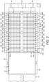
- the combustion chamber 9 comprises a cavity 31, and a floor assembly 32 over which waste product is transferred.
- the cavity 31 is lined at least on opposite side walls thereof with wear-resistant plates 39, which can withstand the high temperature environment.
- the plates 39 each including apertures 40 through which air is delivered over a facing surface thereof from an air supply 41, so as to generate air flows at the opposite side walls which cools the side walls and provides air for combustion within the cavity 31.
- the plates 39 are formed of high-temperature stainless steel.
- the floor assembly 32 comprises a transfer mechanism 42 which provides a grate at the floor of the combustion chamber 9 and transfers waste product which is received from the pre-heating chamber 7 through a combustion zone, and an air supply unit 43 which supplies air to the combustion chamber 9 through the transfer mechanism 42.
- the transfer mechanism 42 comprises at least one stepped assembly 44 over which waste product is transferred.
- the transfer mechanism 42 comprises first and second stepped assemblies 44 which are arranged in adjacent, parallel relation.
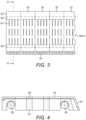
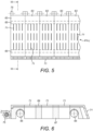
- the at least one stepped assembly 44 comprises a plurality of steps 45a-k, here of fixed position, which are arranged in staggered downward relation, and a plurality of movable members 47a-j which are movable reciprocally in relation to the steps 45a-j to transfer waste product along and over the steps 45a-k.
- the steps 45a-k are arranged substantially in spaced, parallel relation, and the movable members 47a-j are configured such that upper and lower surfaces of the movable members 47a-j are in close relation to adjacent surfaces of the steps 45a-k, whereby the action of withdrawing the movable members 47a-j acts to scrape material therefrom.
- the steps 45a-k comprise substantially-flat plates.
- the steps 45a-k are formed from a plurality of elements 53 which are arranged in adjacent lateral relation.
- the elements 53 are supported by at least one support 55, here first and second elongate bars.
- the elements 53 each comprise a main body part 57, here formed of nodular or stainless steel, and a cover part 59, here formed of stainless steel, preferably high-chrome, nickel stainless steel, which is located over the main body part 57.
- the steps 45a-k include apertures 61 through which an air flow can be driven upwardly into the combustion cavity 31.
- apertures 61 comprise slots, but could have other form.
- the movable members 47a-j comprise substantially-flat plates.
- the movable members 47a-j are formed from a plurality of elements 63 which are arranged in adjacent lateral relation.
- the elements 63 are supported by at least one support 65, here first and second elongate bars.
- the elements 63 each comprise a main body part 67, here formed of nodular or stainless steel, and a cover part 69, here formed of stainless steel, preferably high-chrome, nickel stainless steel, which is located over the main body part 67.
- the movable members 47a-j include apertures 71 through which an air flow is driven upwardly into the cavity 31 of the combustion chamber 9.
- apertures 71 comprise slots, but could have other form.
- the apertures 71 comprise narrow slots having a width of from about 1 mm to about 2 mm, which provide for a high exit velocity, here from about 4 m/s to about 6 m/s, which prevents the slagging of waste product.
- the movable members 47a-j include an attachment 75 to which an actuator (not illustrated) is coupled for moving the movable members 47a-j.
- ones or groups of ones of the movable members 47a-j are movable independently of one another, so as to enable control of an amount of waste product in the combustion zone and hence the rate of burn. This manner of control allows readily for use with different kinds of waste product, which can have different rates of burning, with the rate of transfer being controlled accordingly.
- the movable members 47a-j are configured in a plurality of groups, here comprising a first group 47a-c, a second group 47d-f, a third group 47g-i, and a fourth group 47k.
- the air supply unit 43 comprises a plurality of air supplies 81a-d which supply air to the combustion chamber 9 from beneath the transfer mechanism 42.
- the air supplies 81a-d each comprise a channel 83a-d which has an upper end 85 which opens to a respective region of the transfer mechanism 33 and a supply port 87a-d from which air is delivered from an air source 88.
- the channel 83a-d has an open lower end 89 which opens to a channel 90 which allows for the collection of ash which falls through the transfer mechanism 42.
- the supply ports 85a-d are controllable, here valved, to regulate the rate of flow of air from the respective air supplies 81a-d.
- the floor assembly 32 is integrally formed and the system includes slides 83 on which the floor assembly 32 is slideably disposed, so as to allow easy access to the transfer mechanism 42 and the air supply unit 43.
- the combustion chamber 9 further comprises first and second air inlets 91, 92 which are disposed in a downstream region of the cavity 31 of the combustion chamber 9, with the first air inlet 91 being fluidly connected to an ambient air source 93 which supplies heated ambient air and the second air inlet 92 being fluidly connected to an exhaust gas re-circulation unit 95 which supplies exhaust gas of reduced temperature, and the ambient air source 93 and the exhaust gas re-circulation unit 95 are controlled to temper the temperature of the gas stream, here to a temperature of less than 600 °C.
- the exhaust gas has a temperature of less than about 180 °C.
- NOx emissions can be regulated to comply with environmental regulations.
- the combustion chamber 9 is controlled such that a temperature of about 1200 °C is maintained in the combustion zone at the at least one stepped assembly 44, and such that any material which passes from the combustion chamber 9 has a retention time of greater than 2 s at a temperature of greater than 850 °C.
- the combustion chamber 9 includes at least one burner 87 for igniting the waste product.
- the heat exchanger unit 12 comprises a first, main heat exchanger 96 which is disposed in the post-combustion chamber 11, and a second heat exchanger 97 which is fluidly connected to the vents 27 in the pre-heating chamber 7.
- the second heat exchanger 97 utilizes the heat of the gas stream which is vented through the vents 27 to pre-heat a fluid medium, typically from a temperature of about 70 °C to a temperature of about 180 °C, and the first, main heat exchanger 96 receives the heated fluid medium from the second heat exchanger 97 and utilizes the gas stream which passes through the post-combustion chamber 11 to superheat the fluid medium, typically to a temperature of about 600 °C, which is then used to drive one or more steam generators (not illustrated) to generate power, typically electricity using electrical generators.
- system further comprises a particulate trap 99 which traps particulate material which is in the gas stream leaving the combustion chamber 9 upstream of the first heat exchanger 96, so as to prevent fouling of the first heat exchanger 96.
- the pre-heating chamber 7 can be omitted.
Landscapes
- Engineering & Computer Science (AREA)
- Mechanical Engineering (AREA)
- General Engineering & Computer Science (AREA)
- Chemical & Material Sciences (AREA)
- Combustion & Propulsion (AREA)
- Processing Of Solid Wastes (AREA)
Claims (5)
- Verbrennungsofensystem, welches umfasst:eine Vorheizkammer (7), die das zugeführte Abfallprodukt vorwärmt;eine Verbrennungskammer (9), die das vorgewärmte Abfallprodukt aus der Vorheizkammer (7) aufnimmt und in der das vorgewärmte Abfallprodukt verbrannt wird;worin die Vorheizkammer (7) einen Hohlraum (21) umfasst, durch den das zugeführte Abfallprodukt versetzt wird, und mehrere Lufteinlässe (25), die erwärmte Luft in den Hohlraum (21) der Vorheizkammer (7) einspeisen, und mehrere Entlüftungsöffnungen (27) umfasst, durch die ein Gasstrom entlüftet wird, worin die Vorheizkammer (7) angepasst ist, das zugeführte Abfallprodukt zu erwärmen, um dem zugeführten Abfallprodukt vor der Überführung in die Verbrennungskammer (9) Feuchtigkeit zu entziehen, und eine Temperatur in mindestens einem stromaufwärts gelegenen Bereich des Hohlraums (21) der Vorheizkammer (7) auf weniger als 600°C hält, so dass die Feuchtigkeit aus dem zugeführten Abfallprodukt ohne wesentliche Freisetzung von Chloriden aus dem zugeführten Abfallprodukt entfernt wird;worin die Verbrennungskammer (9) einen Hohlraum (31), einen Überführungsmechanismus (42), der einen Rost an einem Boden der Verbrennungskammer (9) bereitstellt und das vorerhitzte Abfallprodukt durch eine Verbrennungszone überführt, und mehrere Luftzuführungen (81a-d) umfasst, die dem Hohlraum (31) der Verbrennungskammer (9) Luft zuführen;einen ersten Wärmetauscher (96), der mit der Verbrennungskammer (9) fluidmäßig verbunden ist und die Wärme eines erhitzten Gasstroms aus der Verbrennungskammer (9) nutzt;dadurch gekennzeichnet, dass das Verbrennungsofensystem ferner einen zweiten Wärmetauscher (97) umfasst, der mit der Vorwärmkammer (7) fluidmäßig verbunden ist und die Wärme des Gasstroms aus der Vorwärmkammer (7) nutzt, worin ein Auslass des zweiten Wärmetauschers (97) mit einem Einlass des ersten Wärmetauschers (96) fluidmäßig verbunden ist, worin der zweite Wärmetauscher (97) ein Fluidmedium vorwärmt und der erste Wärmetauscher (96) das vorgewärmte, erwärmte Fluidmedium von dem zweiten Wärmetauscher (97) empfängt und das vorgewärmte Fluidmedium weiter erwärmt, um ein überhitztes Fluidmedium bereitzustellen.
- System nach Anspruch 1, worin der Hohlraum (31) der Verbrennungskammer (9) zumindest an seinen gegenüberliegenden Seitenwänden mit hitzebeständigen Platten (39) ausgekleidet ist und die Platten (39) jeweils Öffnungen (40) aufweisen, durch die eine Luftzufuhr über eine ihnen zugewandte Oberfläche erfolgt, so dass an den gegenüberliegenden Seitenwänden des Hohlraums (31) der Verbrennungskammer (9) Luftströme erzeugt werden.
- System nach Anspruch 1 oder 2, worin die Luftzuführungen (81a-d) der Verbrennungskammer (9) Luft von unterhalb des Überführungsmechanismus (42) zuführen.
- System nach Anspruch 3, worin die Luftzuführungen (81a-d) jeweils einen Kanal (83a-d) umfassen, der ein oberes Ende (85), das sich zu einem entsprechenden Bereich des Überführungsmechanismus (42) öffnet, und eine Zuführungsöffnung (87a-d) aufweisen, aus der Luft zugeführt wird.
- System nach Anspruch 4, worin der Kanal (83a-d) ein offenes unteres Ende (89) aufweist, das sich zu einem Kanal (90) öffnet, der das Auffangen von Asche ermöglicht, die durch den Überführungsmechanismus (42) fällt.
Applications Claiming Priority (2)
| Application Number | Priority Date | Filing Date | Title |
|---|---|---|---|
| GB1611997.6A GB2552163B (en) | 2016-07-11 | 2016-07-11 | Combustion kiln system and method of operating the same |
| PCT/EP2017/067304 WO2018011154A1 (en) | 2016-07-11 | 2017-07-10 | Combustion kiln system and method of operating the same |
Publications (2)
| Publication Number | Publication Date |
|---|---|
| EP3482128A1 EP3482128A1 (de) | 2019-05-15 |
| EP3482128B1 true EP3482128B1 (de) | 2023-10-25 |
Family
ID=56890877
Family Applications (1)
| Application Number | Title | Priority Date | Filing Date |
|---|---|---|---|
| EP17746402.1A Active EP3482128B1 (de) | 2016-07-11 | 2017-07-10 | Verbrennungsofensystem und verfahren zum betrieb davon |
Country Status (4)
| Country | Link |
|---|---|
| US (2) | US11002446B2 (de) |
| EP (1) | EP3482128B1 (de) |
| GB (1) | GB2552163B (de) |
| WO (1) | WO2018011154A1 (de) |
Families Citing this family (4)
| Publication number | Priority date | Publication date | Assignee | Title |
|---|---|---|---|---|
| EP3754257A1 (de) * | 2019-06-17 | 2020-12-23 | Tiska GmbH | Komposit-roststab |
| JP2022089410A (ja) * | 2020-12-04 | 2022-06-16 | 天翔 施 | 火格子燃焼システムおよび火格子燃焼方法 |
| JPWO2024043187A1 (de) * | 2022-08-26 | 2024-02-29 | ||
| JP7878146B2 (ja) * | 2023-04-26 | 2026-06-23 | Jfeエンジニアリング株式会社 | 廃棄物焼却方法および廃棄物焼却装置 |
Citations (1)
| Publication number | Priority date | Publication date | Assignee | Title |
|---|---|---|---|---|
| US20050183642A1 (en) * | 2003-06-12 | 2005-08-25 | Basic John N.Sr. | Temperature-controlled incinerator dryer grates |
Family Cites Families (16)
| Publication number | Priority date | Publication date | Assignee | Title |
|---|---|---|---|---|
| US1398718A (en) * | 1917-12-18 | 1921-11-29 | Goder Joseph | Incinerator |
| NL105653C (de) * | 1958-03-12 | |||
| US3321845A (en) * | 1964-10-07 | 1967-05-30 | Abex Corp | Cooling grates |
| CH516770A (de) * | 1967-07-06 | 1971-12-15 | Von Roll Ag | Verfahren und Vorrichtung zum Verbrennen von festen Abfallstoffen |
| US4091748A (en) * | 1976-12-03 | 1978-05-30 | Mansfield Carbon Products, Inc. | Method and apparatus for producing gas from solid municipal waste |
| JPS59125317A (ja) * | 1983-01-07 | 1984-07-19 | Kubota Ltd | 汚泥の乾燥焼却装置 |
| US4732092A (en) * | 1985-09-30 | 1988-03-22 | G.G.C., Inc. | Pyrolysis and combustion apparatus |
| JPH08327041A (ja) * | 1995-06-02 | 1996-12-10 | R B:Kk | 焼却装置 |
| DE69624318T2 (de) * | 1995-07-10 | 2004-01-22 | Hitachi Zosen Corp. | Müllverbrennungssystem |
| JPH0933017A (ja) * | 1995-07-18 | 1997-02-07 | Kubota Corp | ゴミ焼却炉 |
| JPH0949621A (ja) * | 1995-08-09 | 1997-02-18 | Kubota Corp | 焼却炉の空冷壁構造 |
| US6745706B2 (en) * | 2001-10-24 | 2004-06-08 | Richard B. Pallett | Process and apparatus for disposing of municipal solid waste |
| US20100122643A1 (en) * | 2008-11-20 | 2010-05-20 | Cole Arthur W | Modular grate block for a refuse incinerator |
| CN101922715B (zh) * | 2010-09-01 | 2011-12-14 | 重庆科技学院 | 两段式垃圾焚烧炉 |
| CN203404780U (zh) * | 2013-06-28 | 2014-01-22 | 山东宏力空调设备有限公司 | 污泥处理余热回收装置 |
| CN105351944B (zh) * | 2015-12-10 | 2017-12-08 | 重庆三峰卡万塔环境产业有限公司 | 一种改进的炉排炉垃圾焚烧装置 |
-
2016
- 2016-07-11 GB GB1611997.6A patent/GB2552163B/en active Active
-
2017
- 2017-07-10 US US16/317,317 patent/US11002446B2/en active Active
- 2017-07-10 EP EP17746402.1A patent/EP3482128B1/de active Active
- 2017-07-10 WO PCT/EP2017/067304 patent/WO2018011154A1/en not_active Ceased
-
2021
- 2021-05-04 US US17/307,340 patent/US20210254827A1/en not_active Abandoned
Patent Citations (1)
| Publication number | Priority date | Publication date | Assignee | Title |
|---|---|---|---|---|
| US20050183642A1 (en) * | 2003-06-12 | 2005-08-25 | Basic John N.Sr. | Temperature-controlled incinerator dryer grates |
Also Published As
| Publication number | Publication date |
|---|---|
| GB2552163A (en) | 2018-01-17 |
| GB2552163B (en) | 2021-06-16 |
| WO2018011154A1 (en) | 2018-01-18 |
| US20210254827A1 (en) | 2021-08-19 |
| US11002446B2 (en) | 2021-05-11 |
| US20190316771A1 (en) | 2019-10-17 |
| GB201611997D0 (en) | 2016-08-24 |
| EP3482128A1 (de) | 2019-05-15 |
Similar Documents
| Publication | Publication Date | Title |
|---|---|---|
| US20210254827A1 (en) | Combustion kiln system and method of operating the same | |
| KR101428831B1 (ko) | 중회분 건조 추출/ 냉각용 및 고 미연소 성분 잔류물 연소 제어용 플랜트 및 방법 | |
| JP4701138B2 (ja) | ストーカ式焼却炉及びその燃焼制御方法 | |
| US6655304B1 (en) | Mass fuel combustion system | |
| CA2743248A1 (en) | Modular grate block for a refuse incinerator | |
| IES20090762A2 (en) | A by-product energy conversion system | |
| US4955296A (en) | Incinerator grate assembly | |
| RU142005U1 (ru) | Топка с реактором форсированного кипящего слоя | |
| EP2430383B1 (de) | Modul zur verwendung mit einem system zum lateraltransport | |
| CN205102130U (zh) | 一种布风均匀的炉排式焚烧炉 | |
| KR101029906B1 (ko) | 전기효율을 높이고 슬래그 품질을 향상시키며연소배가스로부터 증기를 생성하는 보일러 | |
| US9714766B2 (en) | System for gasifying biomass and other waste | |
| RU2147710C1 (ru) | Топочное устройство для сжигания отходов | |
| EP3106529B1 (de) | Verfahren und anlage zum verhütten von metallen | |
| RU38217U1 (ru) | Котлоагрегат для сжигания фрезерного торфа и древесных отходов в кипящем слое | |
| KR101892907B1 (ko) | 분리형 소각로 자동 처리 설비 | |
| KR200249695Y1 (ko) | 소각로의 연소실 | |
| US732938A (en) | Heating-furnace. | |
| Kantorek et al. | Pilot installation for thermal utilization of meat-and-bone meal using the rotary kiln pyrolyzer and the fluidised bed boiler | |
| JP2002031320A (ja) | 火格子温度の制御方法及び火格子式廃棄物焼却炉 | |
| LV14670B (lv) | Granulu sadedzināšanas iekārta | |
| PL210270B1 (pl) | Sposób i kocioł do kontrolowanego spalania paliw | |
| CA1184075A (en) | Grating structure | |
| SU996795A1 (ru) | Печь дл сжигани отходов | |
| KR20150112269A (ko) | 수냉식 고정수관 화격자를 가진 소각로 |
Legal Events
| Date | Code | Title | Description |
|---|---|---|---|
| STAA | Information on the status of an ep patent application or granted ep patent |
Free format text: STATUS: UNKNOWN |
|
| STAA | Information on the status of an ep patent application or granted ep patent |
Free format text: STATUS: THE INTERNATIONAL PUBLICATION HAS BEEN MADE |
|
| PUAI | Public reference made under article 153(3) epc to a published international application that has entered the european phase |
Free format text: ORIGINAL CODE: 0009012 |
|
| STAA | Information on the status of an ep patent application or granted ep patent |
Free format text: STATUS: REQUEST FOR EXAMINATION WAS MADE |
|
| 17P | Request for examination filed |
Effective date: 20190211 |
|
| AK | Designated contracting states |
Kind code of ref document: A1 Designated state(s): AL AT BE BG CH CY CZ DE DK EE ES FI FR GB GR HR HU IE IS IT LI LT LU LV MC MK MT NL NO PL PT RO RS SE SI SK SM TR |
|
| AX | Request for extension of the european patent |
Extension state: BA ME |
|
| DAV | Request for validation of the european patent (deleted) | ||
| DAX | Request for extension of the european patent (deleted) | ||
| STAA | Information on the status of an ep patent application or granted ep patent |
Free format text: STATUS: EXAMINATION IS IN PROGRESS |
|
| 17Q | First examination report despatched |
Effective date: 20210803 |
|
| GRAP | Despatch of communication of intention to grant a patent |
Free format text: ORIGINAL CODE: EPIDOSNIGR1 |
|
| STAA | Information on the status of an ep patent application or granted ep patent |
Free format text: STATUS: GRANT OF PATENT IS INTENDED |
|
| INTG | Intention to grant announced |
Effective date: 20230214 |
|
| GRAS | Grant fee paid |
Free format text: ORIGINAL CODE: EPIDOSNIGR3 |
|
| GRAA | (expected) grant |
Free format text: ORIGINAL CODE: 0009210 |
|
| STAA | Information on the status of an ep patent application or granted ep patent |
Free format text: STATUS: THE PATENT HAS BEEN GRANTED |
|
| AK | Designated contracting states |
Kind code of ref document: B1 Designated state(s): AL AT BE BG CH CY CZ DE DK EE ES FI FR GB GR HR HU IE IS IT LI LT LU LV MC MK MT NL NO PL PT RO RS SE SI SK SM TR |
|
| REG | Reference to a national code |
Ref country code: GB Ref legal event code: FG4D |
|
| REG | Reference to a national code |
Ref country code: CH Ref legal event code: EP |
|
| REG | Reference to a national code |
Ref country code: DE Ref legal event code: R096 Ref document number: 602017075676 Country of ref document: DE |
|
| REG | Reference to a national code |
Ref country code: IE Ref legal event code: FG4D |
|
| REG | Reference to a national code |
Ref country code: LT Ref legal event code: MG9D |
|
| REG | Reference to a national code |
Ref country code: NL Ref legal event code: MP Effective date: 20231025 |
|
| REG | Reference to a national code |
Ref country code: AT Ref legal event code: MK05 Ref document number: 1625004 Country of ref document: AT Kind code of ref document: T Effective date: 20231025 |
|
| PG25 | Lapsed in a contracting state [announced via postgrant information from national office to epo] |
Ref country code: NL Free format text: LAPSE BECAUSE OF FAILURE TO SUBMIT A TRANSLATION OF THE DESCRIPTION OR TO PAY THE FEE WITHIN THE PRESCRIBED TIME-LIMIT Effective date: 20231025 |
|
| PG25 | Lapsed in a contracting state [announced via postgrant information from national office to epo] |
Ref country code: GR Free format text: LAPSE BECAUSE OF FAILURE TO SUBMIT A TRANSLATION OF THE DESCRIPTION OR TO PAY THE FEE WITHIN THE PRESCRIBED TIME-LIMIT Effective date: 20240126 |
|
| PG25 | Lapsed in a contracting state [announced via postgrant information from national office to epo] |
Ref country code: IS Free format text: LAPSE BECAUSE OF FAILURE TO SUBMIT A TRANSLATION OF THE DESCRIPTION OR TO PAY THE FEE WITHIN THE PRESCRIBED TIME-LIMIT Effective date: 20240225 |
|
| PG25 | Lapsed in a contracting state [announced via postgrant information from national office to epo] |
Ref country code: LT Free format text: LAPSE BECAUSE OF FAILURE TO SUBMIT A TRANSLATION OF THE DESCRIPTION OR TO PAY THE FEE WITHIN THE PRESCRIBED TIME-LIMIT Effective date: 20231025 |
|
| PG25 | Lapsed in a contracting state [announced via postgrant information from national office to epo] |
Ref country code: AT Free format text: LAPSE BECAUSE OF FAILURE TO SUBMIT A TRANSLATION OF THE DESCRIPTION OR TO PAY THE FEE WITHIN THE PRESCRIBED TIME-LIMIT Effective date: 20231025 |
|
| PG25 | Lapsed in a contracting state [announced via postgrant information from national office to epo] |
Ref country code: ES Free format text: LAPSE BECAUSE OF FAILURE TO SUBMIT A TRANSLATION OF THE DESCRIPTION OR TO PAY THE FEE WITHIN THE PRESCRIBED TIME-LIMIT Effective date: 20231025 |
|
| PG25 | Lapsed in a contracting state [announced via postgrant information from national office to epo] |
Ref country code: LT Free format text: LAPSE BECAUSE OF FAILURE TO SUBMIT A TRANSLATION OF THE DESCRIPTION OR TO PAY THE FEE WITHIN THE PRESCRIBED TIME-LIMIT Effective date: 20231025 Ref country code: IS Free format text: LAPSE BECAUSE OF FAILURE TO SUBMIT A TRANSLATION OF THE DESCRIPTION OR TO PAY THE FEE WITHIN THE PRESCRIBED TIME-LIMIT Effective date: 20240225 Ref country code: GR Free format text: LAPSE BECAUSE OF FAILURE TO SUBMIT A TRANSLATION OF THE DESCRIPTION OR TO PAY THE FEE WITHIN THE PRESCRIBED TIME-LIMIT Effective date: 20240126 Ref country code: ES Free format text: LAPSE BECAUSE OF FAILURE TO SUBMIT A TRANSLATION OF THE DESCRIPTION OR TO PAY THE FEE WITHIN THE PRESCRIBED TIME-LIMIT Effective date: 20231025 Ref country code: BG Free format text: LAPSE BECAUSE OF FAILURE TO SUBMIT A TRANSLATION OF THE DESCRIPTION OR TO PAY THE FEE WITHIN THE PRESCRIBED TIME-LIMIT Effective date: 20240125 Ref country code: AT Free format text: LAPSE BECAUSE OF FAILURE TO SUBMIT A TRANSLATION OF THE DESCRIPTION OR TO PAY THE FEE WITHIN THE PRESCRIBED TIME-LIMIT Effective date: 20231025 Ref country code: PT Free format text: LAPSE BECAUSE OF FAILURE TO SUBMIT A TRANSLATION OF THE DESCRIPTION OR TO PAY THE FEE WITHIN THE PRESCRIBED TIME-LIMIT Effective date: 20240226 |
|
| PG25 | Lapsed in a contracting state [announced via postgrant information from national office to epo] |
Ref country code: SE Free format text: LAPSE BECAUSE OF FAILURE TO SUBMIT A TRANSLATION OF THE DESCRIPTION OR TO PAY THE FEE WITHIN THE PRESCRIBED TIME-LIMIT Effective date: 20231025 Ref country code: RS Free format text: LAPSE BECAUSE OF FAILURE TO SUBMIT A TRANSLATION OF THE DESCRIPTION OR TO PAY THE FEE WITHIN THE PRESCRIBED TIME-LIMIT Effective date: 20231025 Ref country code: PL Free format text: LAPSE BECAUSE OF FAILURE TO SUBMIT A TRANSLATION OF THE DESCRIPTION OR TO PAY THE FEE WITHIN THE PRESCRIBED TIME-LIMIT Effective date: 20231025 Ref country code: NO Free format text: LAPSE BECAUSE OF FAILURE TO SUBMIT A TRANSLATION OF THE DESCRIPTION OR TO PAY THE FEE WITHIN THE PRESCRIBED TIME-LIMIT Effective date: 20240125 Ref country code: LV Free format text: LAPSE BECAUSE OF FAILURE TO SUBMIT A TRANSLATION OF THE DESCRIPTION OR TO PAY THE FEE WITHIN THE PRESCRIBED TIME-LIMIT Effective date: 20231025 Ref country code: HR Free format text: LAPSE BECAUSE OF FAILURE TO SUBMIT A TRANSLATION OF THE DESCRIPTION OR TO PAY THE FEE WITHIN THE PRESCRIBED TIME-LIMIT Effective date: 20231025 |
|
| PG25 | Lapsed in a contracting state [announced via postgrant information from national office to epo] |
Ref country code: DK Free format text: LAPSE BECAUSE OF FAILURE TO SUBMIT A TRANSLATION OF THE DESCRIPTION OR TO PAY THE FEE WITHIN THE PRESCRIBED TIME-LIMIT Effective date: 20231025 |
|
| PG25 | Lapsed in a contracting state [announced via postgrant information from national office to epo] |
Ref country code: CZ Free format text: LAPSE BECAUSE OF FAILURE TO SUBMIT A TRANSLATION OF THE DESCRIPTION OR TO PAY THE FEE WITHIN THE PRESCRIBED TIME-LIMIT Effective date: 20231025 |
|
| REG | Reference to a national code |
Ref country code: DE Ref legal event code: R097 Ref document number: 602017075676 Country of ref document: DE |
|
| PG25 | Lapsed in a contracting state [announced via postgrant information from national office to epo] |
Ref country code: SK Free format text: LAPSE BECAUSE OF FAILURE TO SUBMIT A TRANSLATION OF THE DESCRIPTION OR TO PAY THE FEE WITHIN THE PRESCRIBED TIME-LIMIT Effective date: 20231025 |
|
| PG25 | Lapsed in a contracting state [announced via postgrant information from national office to epo] |
Ref country code: SM Free format text: LAPSE BECAUSE OF FAILURE TO SUBMIT A TRANSLATION OF THE DESCRIPTION OR TO PAY THE FEE WITHIN THE PRESCRIBED TIME-LIMIT Effective date: 20231025 Ref country code: SK Free format text: LAPSE BECAUSE OF FAILURE TO SUBMIT A TRANSLATION OF THE DESCRIPTION OR TO PAY THE FEE WITHIN THE PRESCRIBED TIME-LIMIT Effective date: 20231025 Ref country code: RO Free format text: LAPSE BECAUSE OF FAILURE TO SUBMIT A TRANSLATION OF THE DESCRIPTION OR TO PAY THE FEE WITHIN THE PRESCRIBED TIME-LIMIT Effective date: 20231025 Ref country code: EE Free format text: LAPSE BECAUSE OF FAILURE TO SUBMIT A TRANSLATION OF THE DESCRIPTION OR TO PAY THE FEE WITHIN THE PRESCRIBED TIME-LIMIT Effective date: 20231025 Ref country code: DK Free format text: LAPSE BECAUSE OF FAILURE TO SUBMIT A TRANSLATION OF THE DESCRIPTION OR TO PAY THE FEE WITHIN THE PRESCRIBED TIME-LIMIT Effective date: 20231025 Ref country code: CZ Free format text: LAPSE BECAUSE OF FAILURE TO SUBMIT A TRANSLATION OF THE DESCRIPTION OR TO PAY THE FEE WITHIN THE PRESCRIBED TIME-LIMIT Effective date: 20231025 |
|
| PLBE | No opposition filed within time limit |
Free format text: ORIGINAL CODE: 0009261 |
|
| STAA | Information on the status of an ep patent application or granted ep patent |
Free format text: STATUS: NO OPPOSITION FILED WITHIN TIME LIMIT |
|
| REG | Reference to a national code |
Ref country code: DE Ref legal event code: R082 Ref document number: 602017075676 Country of ref document: DE Representative=s name: STRAUS, ALEXANDER, DIPL.-CHEM.UNIV. DR.PHIL., DE |
|
| 26N | No opposition filed |
Effective date: 20240726 |
|
| PG25 | Lapsed in a contracting state [announced via postgrant information from national office to epo] |
Ref country code: SI Free format text: LAPSE BECAUSE OF FAILURE TO SUBMIT A TRANSLATION OF THE DESCRIPTION OR TO PAY THE FEE WITHIN THE PRESCRIBED TIME-LIMIT Effective date: 20231025 |
|
| PG25 | Lapsed in a contracting state [announced via postgrant information from national office to epo] |
Ref country code: SI Free format text: LAPSE BECAUSE OF FAILURE TO SUBMIT A TRANSLATION OF THE DESCRIPTION OR TO PAY THE FEE WITHIN THE PRESCRIBED TIME-LIMIT Effective date: 20231025 |
|
| PG25 | Lapsed in a contracting state [announced via postgrant information from national office to epo] |
Ref country code: MC Free format text: LAPSE BECAUSE OF FAILURE TO SUBMIT A TRANSLATION OF THE DESCRIPTION OR TO PAY THE FEE WITHIN THE PRESCRIBED TIME-LIMIT Effective date: 20231025 |
|
| REG | Reference to a national code |
Ref country code: CH Ref legal event code: PL |
|
| PG25 | Lapsed in a contracting state [announced via postgrant information from national office to epo] |
Ref country code: LU Free format text: LAPSE BECAUSE OF NON-PAYMENT OF DUE FEES Effective date: 20240710 |
|
| PG25 | Lapsed in a contracting state [announced via postgrant information from national office to epo] |
Ref country code: LU Free format text: LAPSE BECAUSE OF NON-PAYMENT OF DUE FEES Effective date: 20240710 |
|
| PG25 | Lapsed in a contracting state [announced via postgrant information from national office to epo] |
Ref country code: CH Free format text: LAPSE BECAUSE OF NON-PAYMENT OF DUE FEES Effective date: 20240731 Ref country code: BE Free format text: LAPSE BECAUSE OF NON-PAYMENT OF DUE FEES Effective date: 20240731 |
|
| REG | Reference to a national code |
Ref country code: BE Ref legal event code: MM Effective date: 20240731 |
|
| PGFP | Annual fee paid to national office [announced via postgrant information from national office to epo] |
Ref country code: GB Payment date: 20250630 Year of fee payment: 9 |
|
| PG25 | Lapsed in a contracting state [announced via postgrant information from national office to epo] |
Ref country code: IE Free format text: LAPSE BECAUSE OF NON-PAYMENT OF DUE FEES Effective date: 20240710 |
|
| PG25 | Lapsed in a contracting state [announced via postgrant information from national office to epo] |
Ref country code: FI Free format text: LAPSE BECAUSE OF FAILURE TO SUBMIT A TRANSLATION OF THE DESCRIPTION OR TO PAY THE FEE WITHIN THE PRESCRIBED TIME-LIMIT Effective date: 20231025 |
|
| PGFP | Annual fee paid to national office [announced via postgrant information from national office to epo] |
Ref country code: DE Payment date: 20250722 Year of fee payment: 9 |
|
| PGFP | Annual fee paid to national office [announced via postgrant information from national office to epo] |
Ref country code: IT Payment date: 20250722 Year of fee payment: 9 |
|
| PGFP | Annual fee paid to national office [announced via postgrant information from national office to epo] |
Ref country code: FR Payment date: 20250725 Year of fee payment: 9 |
|
| PG25 | Lapsed in a contracting state [announced via postgrant information from national office to epo] |
Ref country code: CY Free format text: LAPSE BECAUSE OF FAILURE TO SUBMIT A TRANSLATION OF THE DESCRIPTION OR TO PAY THE FEE WITHIN THE PRESCRIBED TIME-LIMIT; INVALID AB INITIO Effective date: 20170710 |
|
| PG25 | Lapsed in a contracting state [announced via postgrant information from national office to epo] |
Ref country code: HU Free format text: LAPSE BECAUSE OF FAILURE TO SUBMIT A TRANSLATION OF THE DESCRIPTION OR TO PAY THE FEE WITHIN THE PRESCRIBED TIME-LIMIT; INVALID AB INITIO Effective date: 20170710 |
|
| PG25 | Lapsed in a contracting state [announced via postgrant information from national office to epo] |
Ref country code: TR Free format text: LAPSE BECAUSE OF FAILURE TO SUBMIT A TRANSLATION OF THE DESCRIPTION OR TO PAY THE FEE WITHIN THE PRESCRIBED TIME-LIMIT Effective date: 20231025 |