EP3482157B1 - Einstellbare lasernivelliervorrichtung mit distanzmesslasern und selbstnivellierenden lasern und zugehöriges verfahren - Google Patents
Einstellbare lasernivelliervorrichtung mit distanzmesslasern und selbstnivellierenden lasern und zugehöriges verfahren Download PDFInfo
- Publication number
- EP3482157B1 EP3482157B1 EP16908312.8A EP16908312A EP3482157B1 EP 3482157 B1 EP3482157 B1 EP 3482157B1 EP 16908312 A EP16908312 A EP 16908312A EP 3482157 B1 EP3482157 B1 EP 3482157B1
- Authority
- EP
- European Patent Office
- Prior art keywords
- laser
- base
- distance measuring
- leveling
- lasers
- Prior art date
- Legal status (The legal status is an assumption and is not a legal conclusion. Google has not performed a legal analysis and makes no representation as to the accuracy of the status listed.)
- Active
Links
Images




Classifications
-
- G—PHYSICS
- G01—MEASURING; TESTING
- G01C—MEASURING DISTANCES, LEVELS OR BEARINGS; SURVEYING; NAVIGATION; GYROSCOPIC INSTRUMENTS; PHOTOGRAMMETRY OR VIDEOGRAMMETRY
- G01C15/00—Surveying instruments or accessories not provided for in groups G01C1/00 - G01C13/00
- G01C15/002—Active optical surveying means
- G01C15/004—Reference lines, planes or sectors
-
- G—PHYSICS
- G01—MEASURING; TESTING
- G01B—MEASURING LENGTH, THICKNESS OR SIMILAR LINEAR DIMENSIONS; MEASURING ANGLES; MEASURING AREAS; MEASURING IRREGULARITIES OF SURFACES OR CONTOURS
- G01B11/00—Measuring arrangements characterised by the use of optical techniques
- G01B11/02—Measuring arrangements characterised by the use of optical techniques for measuring length, width or thickness
-
- G—PHYSICS
- G01—MEASURING; TESTING
- G01B—MEASURING LENGTH, THICKNESS OR SIMILAR LINEAR DIMENSIONS; MEASURING ANGLES; MEASURING AREAS; MEASURING IRREGULARITIES OF SURFACES OR CONTOURS
- G01B11/00—Measuring arrangements characterised by the use of optical techniques
- G01B11/14—Measuring arrangements characterised by the use of optical techniques for measuring distance or clearance between spaced objects or spaced apertures
-
- G—PHYSICS
- G01—MEASURING; TESTING
- G01C—MEASURING DISTANCES, LEVELS OR BEARINGS; SURVEYING; NAVIGATION; GYROSCOPIC INSTRUMENTS; PHOTOGRAMMETRY OR VIDEOGRAMMETRY
- G01C15/00—Surveying instruments or accessories not provided for in groups G01C1/00 - G01C13/00
- G01C15/002—Active optical surveying means
-
- G—PHYSICS
- G01—MEASURING; TESTING
- G01C—MEASURING DISTANCES, LEVELS OR BEARINGS; SURVEYING; NAVIGATION; GYROSCOPIC INSTRUMENTS; PHOTOGRAMMETRY OR VIDEOGRAMMETRY
- G01C3/00—Measuring distances in line of sight; Optical rangefinders
- G01C3/02—Details
- G01C3/06—Use of electric means to obtain final indication
- G01C3/08—Use of electric radiation detectors
Definitions
- the present invention relates to a laser leveling device as generally described in US Patent Application 14/602,430 (the "'430 Application"), and specifically to certain improvements for the laser leveling device, namely: the use of distance measuring lasers and a self-leveling laser housing in the laser leveling device.
- Patent application US2015/204666 A1 which corresponds to the same applicant as the present invention, relates to an adjustable laser leveling device to facilitate leveling and installation of objects and fixtures, such as shelving and home decor.
- EP1176429 discloses a hand-held distance measuring apparatus based on laser time measurement, which comprises a main body and a target unit.
- US2005111301 discloses a tape measure comprising a waveform range finder.
- the present invention relates to a laser leveling device to facilitate leveling and installation of objects and fixtures, such as shelving, cabinets, and home decor.
- the laser leveling device has one or more bases capable of being temporarily affixed to a wall or other work surface, using known materials such as removable adhesive tabs, strips, mounting screws, nails, pins, magnets, hooks, hoop and loop, or other fasteners now known or hereinafter developed.
- the invention provides a laser leveling device according to claim 1, and a method for locating layout points on a work surface according to claim 12.
- a preferred embodiment of this invention includes a plurality of distance measuring lasers located at predetermined angles in one or more of the bases.
- a base containing the plurality of distance measuring lasers is located over a predetermined reference point on a wall or other work surface (the datum point).
- a datum point as used herein means an initial predetermined reference point on a wall or other work surface and any other reference points identified on the wall or other work surface using the laser leveling device. By placing the laser leveling device over a datum point, a user is able to identify and mark additional points on the wall or other work surface for laying out a project.
- the distance measuring lasers are connected to a power source and a circuit board, or other computer processor, which includes wireless communication capability.
- the handheld display is used to interchangeably interrupt the laser beam emitted from one of the distance measuring lasers, causing the distance from the datum point to the leading edge of the handheld display to be calculated by the computer processor for the distance measuring lasers, and then communicated to and displayed by the handheld display.
- the handheld display in some embodiments is a smartphone or other mobile device with a software application and the ability to communicate wirelessly with the distance measuring lasers.
- a software application on the smartphone allows the distance measurements to be communicated to and displayed on the smartphone when the emitted laser beam from one of the distance measuring lasers is interrupted.
- the smartphone or mobile device in some embodiments includes an attachment to facilitate interruption of the emitted laser beam from the distance measuring laser and marking distances on the wall or other work surface.
- an adjustable sled is used for a smartphone to facilitate moving the smartphone along the beam emitted from the distance measuring laser and to interrupt the beam. The distance between the datum point at the center of the base and the leading edge of the adjustable sled containing the smartphone is displayed in real time on the smartphone.
- distance measuring lasers allows the user to measure distances from the center of a base placed over a datum point without using a tape measure or other distance measuring tool.
- a single distance measuring laser is rotatably attached to a base, allowing the distance measuring laser to be rotated to different angles for measuring distances from the datum point using the handheld display.
- one or more distance measuring lasers is mounted on the laser assembly of the laser leveling device.
- the handheld display includes other functionality such as a stud finder.
- the laser leveling device of this invention includes a laser assembly that is capable of being removably and interchangeably attached to any of the plurality of bases.
- the laser assembly contains a plurality of lasers arranged at predetermined angles, including orthogonal angles, allowing laser lines to be emitted from multiple sides of the laser assembly and projected onto a wall or other work surface so that the laser lines are visible to the user.
- the laser assembly includes a self-leveling laser housing.
- the lasers are adjustably mounted to the housing.
- the housing is movably attachable to the top side of the laser assembly, creating a pendulum that will swing freely when the laser assembly is engaged to a base attached to a vertical work surface.
- the self-leveling laser housing in some embodiments will include means for balancing the self-leveling laser housing and adjusting the roll, pitch, and yaw of each of the plurality of lasers in the housing to allow the lasers to level once the laser assembly is engaged with a base on a wall or other vertical work surface.
- a preferred embodiment of the self-leveling laser housing also includes a prism positioned in the path of each of the plurality of lasers that causes a level, visible beam from each said laser to project as lines on the work surface.
- the present invention advantageously allows level visible laser lines to be established, broadcast, and projected onto a wall or other work surface while the user makes multiple layout marks. More particularly, the present invention facilitates leveling and arrangement of objects on a wall or other work surface by allowing the user to easily measure distances from a datum point to additional points in the layout, along level, visible laser lines projected onto the work surface. Additional bases may be placed over other reference points on the work surface, which reference points originate from the initial datum point.
- the use of more than one base in any layout allows the laser assembly to be moved from base to base effectively and efficiently within said layout field without interrupting previously identified marks in the layout.
- An alternative embodiment of the present invention is a laser leveling device with a base that is capable of being removably affixed to a wall or other work surface and one or more distance measuring lasers rotatably mounted to said the base, wherein the user is able to rotatably adjust the distance measuring lasers to orient the lasers to a desired position for measuring distances in various directions and at various angles from the center of the base.
- a further alternative embodiment of the present invention is a laser assembly with one or more lasers where the laser assembly is rotatably and removably attached to a base, wherein the user is able to rotatably adjust the laser assembly on said base to orient the lasers in the laser assembly to a desired position.
- the laser assembly and a base are coupled together to form a single integrated device.
- Uses of the present invention may relate to, for example, hanging shelving, pictures, collages, artwork, closet shelving, decorative shelving, curtain rods, towel bars, fixed hang holes, tile work, cabinets, built-in cabinets/shelving, kitchen cabinets, door hardware, wall mounted lighting fixtures, flat screen TV mounts, and other installations.
- the invention provides a laser leveling device characterized by one or more horizontal and/or vertical lasers integrated into a laser assembly.
- the lasers in the laser assembly are self-leveling and project level laser lines onto a work surface when the laser leveling device is removably attached to the work surface.
- the laser leveling device includes one or more bases to which the laser assembly is capable of being removably and interchangeably attached.
- One or more of the bases for the laser leveling device contain one or more distance measuring lasers that allow the user to measure distances from the center of the base along the laser lines projected by the laser assembly along on the work surface.
- the distance measuring lasers in some embodiments are mounted onto or within the laser assembly.
- the laser leveling device has a plurality of bases with one or more distance measuring lasers mounted on one or more of said bases.
- the distance measuring lasers on said bases are connected to a power source and a circuit board, or other computer processor, which includes wireless communication capability.
- a base containing the one or more distance measuring lasers is placed over a datum point and the distance measuring lasers are powered on, a user is able to determine the distance from the datum point using a handheld display that communicates with the distance measuring lasers using Bluetooth or other wireless communications now known in the industry or hereinafter developed.
- the handheld display is used to interchangeably interrupt the laser beam emitted from one of the distance measuring lasers, causing the distance from the datum point to the leading edge of the handheld display to be calculated by the computer processor for the distance measuring lasers, and then communicated to and displayed by the handheld display.
- the handheld display has wireless connectivity with the distance measuring lasers in one of the plurality of bases using Bluetooth or other wireless communication.
- the handheld display also has LCD readout for displaying measurements.
- the handheld display provides a continuous readout of distances as it is moved along the distance measuring laser.
- the handheld display in some embodiments is a smartphone or other mobile device with a software application for calculating and displaying distances when the laser beam emitted from a distance measuring laser is interrupted.
- the handheld display may also include other functions, such as a stud finder.
- another object, device, or tool is used to interrupt the distance measuring laser, causing the distance to be displayed on the handheld device or on a separate display in close proximity to the distance measuring lasers.
- one or more distance measuring lasers is rotatably and removably attached to a base, allowing the distance measuring device to be rotated to different angles for measuring distances from the center of said base.
- each of the plurality of bases is capable of being removably affixed to the work surface, using known materials such as removable adhesive tabs, strips, mounting screws, nails, pins, hooks, magnets, hoop and loop, or other known fasteners.
- Each of the plurality of bases has a bull's-eye-like, open hole at the center, allowing the user to align each of the bases over datum points on the work surface.
- each of the bases is capable of being aligned over datum points using other means, such as magnets or sensors placed on the work surface.
- the laser leveling device includes a laser assembly that is capable of being removably and interchangeably attached to any of the plurality of bases.
- Said laser assembly contains a plurality of lasers arranged at preferred angles, including orthogonal angles, allowing laser lines to be emitted out of multiple sides of the laser leveling device and projected onto a wall or other work surface.
- the lasers in the laser assembly are provided in a self-leveling laser housing.
- a preferred embodiment of the self-leveling lasers includes mounting the plurality of lasers in a housing that is movably attached to the top side of the laser assembly (when mounted on a base attached to a work surface), thereby creating a pendulum for the housing containing the plurality of lasers.
- the self-leveling laser housing When the laser assembly with the self-leveling laser housing is attached to a base on a work surface, the self-leveling laser housing swings freely, leveling the lasers.
- the self-leveling laser housing also includes means for balancing the self-leveling laser housing and adjusting roll, pitch, and yaw of the lasers mounted to the housing to ensure that the lasers will level automatically when attached to a work surface.
- the preferred embodiment of the self-leveling laser housing also includes a prism positioned in the path of each of the plurality of lasers mounted to the housing. The beams from each of the lasers pass through the prism causing the beams to be projected onto the work surface when the laser assembly is attached to a base mounted on the work surface.
- the present invention advantageously allows level laser lines to be established, broadcast, and held on a work surface while the user makes multiple layout marks. More particularly, the present invention facilitates leveling and arrangement of objects on a wall or other work surface by allowing the user to easily move the laser assembly to a plurality of bases attached to the work surface to facilitate and expedite making multiple layout marks on the work surface and thereby successfully laying out a project.
- FIG. 1 shows a top view of a preferred embodiment of the laser leveling device 100 of the present invention and specifically shows a base 101 , the laser assembly 102 with four lasers 103 installed at orthogonal angles in the laser assembly 102.
- FIG. 1 also shows a power button 106 for powering on one or more of the lasers 103, and a level assembly 104 that is removably attached to the base of the laser leveling device 100 .
- a laser line is capable of being emitted from each side of the laser assembly 102 with laser lines emitted at predetermined angles, including orthogonal angles, across the wall or other work surface.
- the laser leveling device 100 includes a plurality of bases 101 .
- the use of multiple bases 101 allows a user to expand layout possibilities by aligning the bases 101 over datum points on a work surface and then moving the laser assembly 102 from base 101 to base 101 to provide additional reference lines.
- bases 101 include openings that allow laser lines to pass through, over, and/or underneath the bases 101 for accurate alignment of the bases 101 and assistance with creating a grid of leveled laser lines on a work surface.
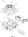
- FIG. 2 is a perspective, exploded view of a preferred embodiment of a laser leveling device 100 of the present invention, including a base 101 , a laser assembly 102 , which is removably attachable to the base 101 by aligning the corner depressions 110 to the pillars 108 on the base 101 .
- FIG. 2 also shows a plurality of distance measuring lasers 150 located at or near the center of the base 101 .
- the distance measuring lasers 150 are connected to a power source and a circuit board, or other computer processor, which includes wireless communication capability.
- the power source and circuit board are located on the base 101 with the distance measuring lasers 150 , but are not shown in FIG. 2 .
- the computer processor connected to the distance measuring lasers 150 calibrates the distance measuring lasers so that distances are measured from the center of the base 101 when the base 101 is located over a datum point.
- FIG. 2 further shows a handheld display 151 that wirelessly communicates with the plurality of distance measuring lasers 150 using Blue Tooth or other means known in the art. Distances are measured from the center of the base 101 by identifying the direction in which the measurement is to be made, powering on the distance measuring laser 150 aligned in said direction and interrupting the beam emitted 166 from one of the distance measuring lasers 150 using the handheld display 151 . When the beam from the distance measuring laser 150 is interrupted, the handheld display 151 will display in real time the distance from the center of the base 101 .
- the distance measuring lasers 150 are not visible to the human eye, will not project onto the work surface, and will not disrupt or interfere with the visibility of the lasers 103 of the laser assembly 102 , which will project onto the work surface.
- FIG. 2 also shows a bull's-eye opening 107 at the center of the base 101 to facilitate locating the base 101 over a datum point.
- FIG. 2 also shows a laser assembly 102 with lasers 103 , a power button 106 for the lasers 103 in the laser assembly 102 and corner depressions 110 for aligning and removably attaching the laser assembly 102 to the base 101 .
- the laser assembly 102 when the laser assembly 102 is removably attached to a base 101 that is removably mounted onto the work surface and the lasers 103 in the laser assembly 102 are activated, the lasers 103 will emit and project visible, level laser lines onto the work surface.
- FIG. 2 further shows a level assembly 104 , comprising a torpedo level with both horizontal 115 and vertical 116 vials for leveling the base 101 and thus the laser lines emitted from a laser assembly 102 .
- the level assembly 104 is capable of being removably attachable to a base 101 or located adjacent to a base 101 using magnets, Velcro, or other fasteners.
- the level assembly 104 is capable of being used to manually level a base 101 when it is removably attached to a work surface or to level the entire laser leveling device 100 that is attached to a work surface.
- FIG. 3 is a top view of a base 101 showing a plurality of distance measuring lasers 150 located at or near the center of the base 101 .
- FIG. 3 also shows a bull's eye opening 107 at the center of the base 101 for positioning the base 101 over a datum point on a work surface and four pillars 108 that receive and secure the laser assembly 102 to the base 101 .
- each of the distance measuring lasers is calibrated to provide distance measurements from the center of the base 101 .
- the distance measuring lasers 150 on the base 101 are electronics (not shown in FIG. 3 ) known to one skilled in the art such as batteries or other sources of power for the distance measuring lasers 150, a power switch, a circuit board or other computer processor, and a means for wirelessly communicating with the handheld display 151.
- the handheld display has a LCD display or other similar display, other electronic components known in the art, and communicates with the distance measuring lasers 150 using Bluetooth or other means of wireless communication.
- the handheld display 151 interrupts the selected distance measuring laser 150 the distance from the center of the base 101 is calculated and displayed on the LCD screen of the handheld display 151.
- the handheld display 151 is moved along the emitted laser beam 166 for the selected distance measuring laser 150 the distance from the center of the base 101 will be displayed continuously and in real-time.
- the handheld display is a smartphone or other mobile device 165 that communicates by Blue Tooth or other wireless means with the distance measuring lasers 150 and includes a software application 161 that allows the smartphone 165 to calibrate and display distances from the center of the base 101 when the emitted laser beam 166 is interrupted.
- a user may attach a side rail or an adjustable cradle 162 to the smartphone 165 to facilitate interruption of the beam from one of the distance measuring lasers 150 and assist in placing marks on the work surface.
- the distance measuring lasers 150 are not projected onto the work surface and are not generally visible to the user.
- the distance measuring lasers 150 are installed in one or more bases 101 and are aligned on the same axes as the lasers 103 installed in the laser assembly 102.
- the lasers 103 in the laser assembly are projected onto the work surface and as such are visible to the user.
- the user is able to measure distances along the projected laser lines on the work surface by moving the handheld display 151 along the projected laser lines thereby interrupting the beam from the distance measuring lasers 150 that are aligned on the same axes as the laser assembly 102 lasers 103.
- the distance measuring lasers 150 will operate independently from the lasers 103 in the laser assembly 102.
- the distance measuring lasers 150 are capable of being mounted at or near the center of the base 101 on the same axes as the lasers 103 in the laser assembly 102.
- one or more distance measuring lasers 150 are capable of being rotatably mounted at or near the center of the base 101 to allow the one or more distance measuring lasers 150 to be rotatably aligned to the same axes as the lasers 103 in the laser assembly 102.
- one or more distance measuring lasers 150 is installed on or in the laser assembly 102 and aligned on the same axes as the lasers 103 projecting onto the work surface.
- the distance measuring lasers 150 do not necessarily require a separate power source or power button 106 and are capable of utilizing the power source and power button 106 for the laser assembly 102.
- the handheld display 151 includes a stud finder to allow a user to identify studs in the work surface and measure the distance from the center of the base 101 to the stud.
- an object, device, or tool, other than the handheld display is used to interrupt the distance measuring laser, causing the distance to be displayed on the handheld device or on a separate display in close proximity to the distance measuring lasers.
- FIG. 5 is a perspective view of a preferred embodiment of the laser assembly 102 of the present invention.
- FIG. 5 shows lasers 103 positioned at right angles in the laser assembly 102, a power button 106 for powering on and off the lasers 103 in the laser assembly 102 and corner depressions 110 for aligning and removably attaching the laser assembly 102 to a base 101.
- FIG. 6 is an exploded view of a preferred embodiment of the laser assembly 102 of the present invention, showing an upper enclosure 113 of the laser assembly 102, a plurality of lasers 103 installed on a housing 152, and a bottom enclosure 114 for the laser assembly 102.
- the laser assembly 102 also includes batteries or other means for powering the lasers 103 and a power button 106 for powering the lasers 103 on and off.
- the power button 106 is capable of being configured to activate an individual laser 103 or multiple lasers 103.
- the laser assembly 102 in some embodiments is also configured with multiple power buttons for different lasers 103.
- a single click of a power button 106 enables horizontal lasers 103
- a second click enables vertical lasers 103
- a third click enables all lasers 103
- a subsequent click disables all lasers 103.
- the lasers 103 in the laser assembly 102 are adjustably mounted and aligned in a self-leveling laser housing 152 that is movably attached inside the laser assembly 102 so that the top 169 of the housing 152 is at the top 170 of the laser assembly 102 when the laser assembly 102 is attached to a base 101 removably mounted onto a vertical work surface.
- the housing 152 will swing as a pendulum when the laser assembly 102 is attached with a base 101 that is mounted on a wall or other vertical work surface. The pendulum action of the housing 152 allows the lasers 103 to self-level.
- FIG. 6 also shows electrical wires 168 for connecting the lasers 103 to the electrical components of the laser assembly 102, including batteries or other power source and the power button 106.
- FIGS. 7-10 show further details of the self-leveling laser housing 152 of the present invention.
- FIG. 7 is a top perspective view of the self-leveling laser housing 152 showing four lasers 103 mounted and aligned on the housing 152.
- FIG. 7 also shows a balance weight adjustment 156 for balancing the housing 152 to ensure the pendulum action of the housing 152 is properly balanced.
- FIG. 7 further shows screw adjustments 155 for adjusting the yaw of the mounted lasers 103.
- other known means for adjusting the balance and yaw will be utilized.
- the pitch and roll of the lasers are set during assembly and are not adjustable.
- the housing 152 includes screw adjustments or other means for adjusting roll 160, pitch 159, and yaw 155 of the lasers 103 as illustrated in FIG. 10 .
- FIG. 7 also shows electrical wires 168 for connecting the lasers 103 to the electrical components of the laser assembly 102, including batteries or other power source and the power button 106.
- a preferred embodiment of the present invention also includes prisms 157 located in front of each laser 103 in the laser assembly 102.
- the prisms 157 cause the emitted laser beams from the lasers 103 to project onto the work surface when the lasers 103 are powered on, allowing a user to see a level laser lines projected onto the work surface.
- FIG. 8 is a back perspective view of the self-leveling laser housing 152, showing the pivot bearing 158 that movably attaches to the bottom enclosure 114 of the laser assembly 102, allowing the housing 152 to swing freely as a pendulum when the laser assembly 102 is attached to a base 101 that is mounted to a vertical work surface.
- FIG. 8 also shows the lasers 103 adjustably mounted on the housing 152, balancing weights 156 to balance the pendulum action of the housing 152, the yaw adjustments 155 for the lasers 103, and the prisms 157 mounted in front of the lasers 103.
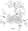
- FIG. 9 is an exploded perspective view of the self-leveling laser housing 152, showing the lasers 103, the yaw adjustments 155, the weight balance adjustments 156, the pivot bearing 158, and the prisms 157.
- FIG 10 is a partial view of the self-leveling laser housing 152, which shows an alternative embodiment of the housing 152 utilizing multi-axis adjustments, including pitch adjustments 159, yaw adjustments 155, and roll adjustments 160.
- the laser leveling device 100 contains a master power button 106 for the laser assembly 102 and a separate button for cycling to different lasers 103 of the laser assembly 102.
- the housing 152 is locked in place by a pin or similar fastener and not allowed to swing as a pendulum.
- the power button 106 is moved to the on position, the housing 152 is unlocked, allowing it to swing freely as a pendulum and allowing the lasers 103 to self-level.
- the separate laser cycle button is used to cycle on one or more of the lasers 103 in the laser assembly 102.
- a plurality of bases 101 is utilized with one of the bases 101 arranged on the work surface near laser lines emitted from a laser assembly 102 removably attached to another of the plurality of bases 101 on the work surface.
- the visible, level laser lines from the laser assembly 102 pass through an opening in the base 101 or under the base 101 without being interrupted to allow for alignment of the bases 101 along the level laser lines.
- the laser leveling device 100 comprises a plurality of bases 101 and a plurality of laser assemblies 102 whereby multiple bases 101 affixed on the work surface have laser assemblies 102 removably attached, allowing level, visible laser lines to be projected onto the work surface from more than one laser assembly 102 at a time, thereby creating a visible grid of level laser lines on the work surface to facilitate project layout.
- a laser assembly 102 is capable of being rotatably attached to a base 101 allowing the user to set various degrees of laser orientation from a base 101 removably attached to a work surface.
- the center of a base 101 will rotate on ball bearings, allowing the distance measuring lasers 150 and the laser assembly 102 to rotate to different angles when attached to the base 101.
- a base 101 includes a center disc or other means for rotating the distance measuring lasers 150 and the laser assembly 102 at various degrees around the center of the base 101. The distance measuring lasers 150 of various embodiments rotate with or separately from the laser assembly 102.
- the self-leveling laser housing 152 of the present invention When the self-leveling laser housing 152 of the present invention is used with a rotating laser assembly 102, the self-leveling laser housing 152 has a means, such as a pin or screw, for locking the housing in place once the lasers 103 are set to the preferred angle and level.
- the laser assembly 102 is capable of being permanently affixed to a base 101, forming an integrated laser leveling device 100.
- the laser assembly 102 includes lasers at angles other than orthogonal angles.
- the lasers may be provided at every 45 degrees and other common angles.
- the laser leveling device 100 is capable of being configured in various sizes and shapes. However, a size and shape that can be easily lifted and moved with one hand is preferred.
- the plurality of bases 101 is rectangular with a length and width ranging between 21 ⁇ 2 inches to approximately 51 ⁇ 2 inches without limitation.
- the thickness of the base 101 in one embodiment is approximately 1 ⁇ 2 inch. A thinner base will be utilized in other embodiments to ensure the distance measuring lasers 150 are not too far removed from the work surface, advantageously increasing accuracy in measurements along the projected laser lines.
- the bases 101 and the upper enclosure 113 and bottom enclosure 114 of the laser assembly 102 are manufactured from plastic materials to provide light weight and ease of use. However, other materials will also be used in various embodiment of the invention.
- the lasers 103 are laser diodes, but other lasers will be used in various embodiments of the invention.
Landscapes
- Physics & Mathematics (AREA)
- General Physics & Mathematics (AREA)
- Engineering & Computer Science (AREA)
- Radar, Positioning & Navigation (AREA)
- Remote Sensing (AREA)
- Electromagnetism (AREA)
- Conveying And Assembling Of Building Elements In Situ (AREA)
Claims (14)
- Lasernivelliervorrichtung (100) aufweisend:eine erste Grundfläche (101) mit einem Mittel zum Zentrieren der ersten Grundfläche (101) über einem ersten Bezugspunkt an einer Arbeitsfläche;eine erste Laserbaugruppe (102) aufweisend ein erstes Lasergehäuse, welches einen darauf angebrachten ersten Nivellierlaser (103) enthält, wobei das erste Lasergehäuse ein selbstnivellierendes Lasergehäuse (152) ist, welches es ermöglicht, den ersten Nivellierlaser (103) zu nivellieren, wenn der Laser (103) aktiviert ist;ein Mittel zum entfernbaren Anbringen der ersten Grundfläche (101) an der Arbeitsfläche;ein Mittel zum entfernbaren Anbringen der ersten Laserbaugruppe (102) an der ersten Grundfläche (101);ein Mittel zum Aktivieren des ersten Nivellierlasers (103), wodurch bewirkt wird, dass ein erster Nivellierlaserstrahl des ersten Nivellierlasers (103) als eine sichtbare Linie auf die Arbeitsfläche projiziert wird;dadurch gekennzeichnet, dass die Lasernivelliervor-richtung (100) ferner aufweist:einen ersten Entfernungsmesslaser (150) angebracht an der ersten Grundfläche (101);ein Mittel zum Aktivieren des ersten Entfernungsmesslasers (150), wodurch bewirkt wird, dass der erste Entfernungsmesslaser (150) einen ersten Entfernungsmesslaserstrahl (166) aussendet; undeine tragbare Vorrichtung, welche drahtlos mit dem ersten Entfernungsmesslaser (150) kommuniziert, wobei die tragbare Vorrichtung dazu verwendet wird, den ersten Entfernungsmesslaserstrahl (166) zu unterbrechen und die Entfernung zwischen dem Zentrum der ersten Grundfläche (101), an welchem der erste Entfernungsmesslaser (150) angebracht ist, und dem Punkt, an welchem die tragbare Vorrichtung den ersten Entfernungsmesslaserstrahl (166) unterbricht, anzuzeigen.
- Lasernivelliervorrichtung (100) nach Anspruch 1, wobei der erste Nivellierlaser (103) rund um das Zentrum der ersten Grundfläche (101) gedreht werden kann, wenn die erste Laserbaugruppe (102) entfernbar an der ersten Grundfläche (101) angebracht ist.
- Lasernivelliervorrichtung (100) nach Anspruch 1, wobei der erste Nivellierlaser (150) entlang derselben Achsen ausgerichtet ist, wie der erste Nivellierlaser (103), wenn die erste Laserbaugruppe (102) entfernbar an der ersten Grundfläche (101) angebracht ist.
- Lasernivelliervorrichtung (100) nach Anspruch 3, wobei der erste Entfernungsmesslaser (150) rund um den Mittelpunkt der ersten Grundfläche (101) gedreht werden kann.
- Lasernivelliervorrichtung (100) nach Anspruch 1, wobei die erste Laserbaugruppe (102) eine obere Einfassung (113) und eine untere Einfassung (114), eine Batterie zum Speisen des ersten Nivellierlasers (103), einen Leistungsschalter zum Aktivieren des ersten Nivellierlasers (103) und ein Mittel zum entfernbaren und austauschbaren Verbinden der ersten Laserbaugruppe (102) mit der ersten Grundfläche (101) aufweist.
- Lasernivelliervorrichtung (100) nach Anspruch 1, wobei das erste Lasergehäuse ein Mittel zum Ausgleichen des ersten Lasergehäuses und zum Anpassen von Längsachse (159), Querachse (160) und Neigungsachse (155) des ersten Nivellierlasers (103) aufweist.
- Lasernivelliervorrichtung (100) nach Anspruch 1, wobei das erste Lasergehäuse ein Prisma (157), welches vor dem ersten Nivellierlaser (103) angeordnet ist, aufweist, wodurch bewirkt wird, dass der erste Nivellierlaserstrahl auf die Arbeitsfläche projiziert wird und für einen Benutzer sichtbar ist, wenn der erste Nivellierlaser (103) aktiviert ist.
- Lasernivelliervorrichtung (100) nach Anspruch 1, wobei der erste Entfernungsmesslaser (150) mit einer Batterie zum Speisen des ersten Entfernungsmesslasers (150), einem Leistungsschalter zum Aktivieren des ersten Entfernungsmesslasers (150) und einem Mittel zum drahtlosen Kommunizieren mit der tragbaren Vorrichtung verbunden ist.
- Lasernivelliervorrichtung (100) nach Anspruch 1, wobei die tragbare Vorrichtung ein Smartphone (165) ist, welches eine Softwareanwendung (161) zum Berechnen und Anzeigen von Entfernungen, wenn der erste Entfernungsmesslaserstrahl (166) unterbrochen wird, aufweist.
- Lasernivelliervorrichtung (100) nach Anspruch 1, wobei die tragbare Vorrichtung ein Smartphone (165) und eine einstellbare Halterung (162) für das Smartphone (165), welche die Unterbrechung des ersten Entfernungsmesslaserstrahls (166) erleichtert, aufweist.
- Lasernivelliervorrichtung (100) nach Anspruch 1, wobei die erste Grundfläche (101) und die erste Laserbaugruppe (102) miteinander gekoppelt sind, wodurch sie eine integrierte Lasernivelliervorrichtung bilden.
- Verfahren zum Bestimmen von Layoutpunkten an einer Arbeitsfläche, umfassend:entfernbares Anbringen einer ersten Grundfläche (101) an der Arbeitsfläche über einem Bezugspunkt;Nivellieren der ersten Grundfläche (101) horizontal und vertikal an der Arbeitsfläche;entfernbares Anbringen einer Laserbaugruppe (102) an der ersten Grundfläche (101), wobei die Laserbaugruppe (102) einen oder mehrere Laser (103) enthält, welche/r an einem selbstnivellierenden Lasergehäuse (152) angebracht ist/sind, welches es ermöglich, die Laser (103) zu nivellieren, wenn sie aktiviert werden; Aktivieren des einen oder der mehreren Laser/s (103), welche/r am selbstnivellierenden Lasergehäuse (152) angebracht ist/sind, wodurch bewirkt wird, dass ein oder mehrere ebene, sichtbare Laserlinien auf die Arbeitsfläche projiziert werden, dadurch gekennzeichnet, dass ein oder mehrere Entfernungsmesslaser (150), welche/r an der ersten Grundfläche (101) angebracht ist/sind, aktiviert werden, wodurch bewirkt wird, dass der eine oder die mehreren Entfernungsmesslaser (150) einen oder mehrere Laserstrahlen (166) aussendet/aussenden;Ausrichten des einen oder der mehreren Entfernungsmesslaser(s) (150), welche/r an der ersten Grundfläche (101) angebracht ist/sind, wodurch bewirkt wird, dass der eine oder die mehreren von den Entfernungsmesslasern (150) ausgesendeten Laserstrahl/en (166) entlang derselben Achsen angeordnet ist/sind, wie die eine oder die mehreren auf die Arbeitsfläche projizierte/n sichtbare/n Laserlinie(n); undMessen der Entfernungen vom Zentrum der ersten Grundfläche (101) entlang der einen oder der mehreren sichtbaren Laserlinie/n, welche auf die Arbeitsfläche projiziert wird/werden, unter Verwendung einer tragbaren Vorrichtung, welche drahtlos mit dem einen oder den mehreren Entfernungsmesslaser(n) (150) kommuniziert, wobei die tragbare Vorrichtung dazu verwendet wird, den von dem einem oder einem der mehreren Entfernungsmesslaser (150), welche/r an der ersten Grundfläche (101) angebracht ist/sind, ausgesendeten Laserstrahl (166) austauschbar zu unterbrechen und die Entfernung zwischen dem Zentrum der ersten Grundfläche (101) und dem Punkt, an welchem die tragbare Vorrichtung den ausgesendeten Laserstrahl (166) unterbricht, anzuzeigen.
- Verfahren nach Anspruch 12, ferner umfassend:Markieren eines zweiten Bezugspunkts an der Arbeitsfläche in einem entsprechenden Abstand und einer entsprechenden Richtung vom Zentrum der ersten Grundfläche (101);Zentrieren und entfernbares Anbringen einer zweiten Grundfläche (101) über dem zweiten Bezugspunkt an der Arbeitsfläche, wobei ein oder mehrere Entfernungsmesslaser (150) an der zweiten Grundfläche (101) angebracht werden;Nivellieren der zweiten Grundfläche (101) horizontal und vertikal an der Arbeitsfläche;Entfernen der Laserbaugruppe (102) von der ersten Grundfläche (101) und entfernbares Anbringen der Laserbaugruppe (102) an der zweiten Grundfläche (101);Aktivieren des einen oder der mehreren Laser/s (103), welche/r am selbstnivellierenden Lasergehäuse (152) angebracht ist/sind, wodurch bewirkt wird, dass eine oder mehrere ebene, sichtbare Laserlinie/n von der Laserbaugruppe (102), welche an der zweiten Grundfläche (101) angebracht ist, auf die Arbeitsfläche projiziert wird/werden;Aktivieren des einen oder der mehreren Entfernungsmesslaser (150), welche/r an der zweiten Grundfläche (101) angebracht ist/sind, wodurch bewirkt wird, dass die Entfernungsmesslaser (150), welche an der zweiten Grundfläche (101) angebracht sind, einen oder mehrere Laserstrahlen (166) aussenden;Ausrichten des einen oder der mehreren Entfernungsmesslaser(s) (150), welche/r an der zweiten Grundfläche (101) angebracht ist/sind, wodurch bewirkt wird, dass der eine oder die mehreren von den Entfernungsmesslasern (150), welche an der zweiten Grundfläche (101) angebracht sind, ausgesendete/n Laserstrahl/en (166) entlang derselben Achsen angeordnet ist/sind, wie die eine oder die mehreren von der Laserbaugruppe (102), welche an der zweiten Grundfläche (101) angebracht ist, auf die Arbeitsfläche projizierte/n sichtbare/n Laserlinie(n); undMessen der Entfernungen vom Zentrum der zweiten Grundfläche (101) entlang der einen oder den mehreren sichtbaren Laserlinie/n, welche von der Laserbaugruppe (102), welche an der zweiten Grundfläche (101) angebracht ist, auf die Arbeitsfläche projiziert wird/werden, unter Verwendung einer tragbaren Vorrichtung, welche drahtlos mit dem einen oder den mehreren Entfernungsmesslaser(n) (150), welche/r an der zweiten Grundfläche (101) angebracht ist/sind, kommuniziert, wobei die tragbare Vorrichtung dazu verwendet wird, den von dem einen oder den mehreren Entfernungsmesslaser(n) (150), welche/r an der zweiten Grundfläche (101) angebracht ist/sind, ausgesendeten Laserstrahl austauschbar zu unterbrechen und die Entfernung zwischen dem Zentrum der zweiten Grundfläche (101) und dem Punkt, an welchem die tragbare Vorrichtung den ausgesendeten Laserstrahl (166) unterbricht, anzuzeigen.
- Verfahren nach Anspruch 13, ferner umfassend:Markieren eines dritten Bezugspunkts an der Arbeitsfläche in einer entsprechenden Entfernung vom Zentrum der zweiten Grundfläche (101); undMessen und Markieren zusätzlicher Bezugspunkte von der ersten und der zweiten Grundfläche (101) aus, bis das Layout vollständig ist.
Applications Claiming Priority (1)
| Application Number | Priority Date | Filing Date | Title |
|---|---|---|---|
| PCT/US2016/041295 WO2018009193A1 (en) | 2016-07-07 | 2016-07-07 | Adjustable laser leveling device with distance measuring lasers and self-leveling lasers and related method |
Publications (3)
| Publication Number | Publication Date |
|---|---|
| EP3482157A1 EP3482157A1 (de) | 2019-05-15 |
| EP3482157A4 EP3482157A4 (de) | 2020-04-22 |
| EP3482157B1 true EP3482157B1 (de) | 2021-10-27 |
Family
ID=60912239
Family Applications (1)
| Application Number | Title | Priority Date | Filing Date |
|---|---|---|---|
| EP16908312.8A Active EP3482157B1 (de) | 2016-07-07 | 2016-07-07 | Einstellbare lasernivelliervorrichtung mit distanzmesslasern und selbstnivellierenden lasern und zugehöriges verfahren |
Country Status (5)
| Country | Link |
|---|---|
| US (2) | US11300410B2 (de) |
| EP (1) | EP3482157B1 (de) |
| CA (1) | CA3030106C (de) |
| ES (1) | ES2904489T3 (de) |
| WO (1) | WO2018009193A1 (de) |
Cited By (1)
| Publication number | Priority date | Publication date | Assignee | Title |
|---|---|---|---|---|
| US11994389B2 (en) | 2016-07-07 | 2024-05-28 | Sure Hang, Llc | Adjustable laser leveling device with distance measuring lasers and self-leveling lasers and related method |
Families Citing this family (10)
| Publication number | Priority date | Publication date | Assignee | Title |
|---|---|---|---|---|
| EP3511272A1 (de) * | 2018-01-16 | 2019-07-17 | Logevo AB | Positionierungsbestimmungsvorrichtung und verfahren zur bestimmung der position eines gatters |
| GB202014590D0 (en) | 2020-09-16 | 2020-10-28 | Stanley Works Israel | Laser tool and system |
| EP4006489A1 (de) * | 2020-11-30 | 2022-06-01 | Hilti Aktiengesellschaft | Ziel- und leitungssystem zur übertragung eines interessierenden punktes auf einer baustellenfläche |
| WO2022216611A1 (en) * | 2021-04-05 | 2022-10-13 | Milwaukee Electric Tool Corporation | Rotary laser with mechanical mask |
| US12158331B2 (en) | 2021-09-17 | 2024-12-03 | Hydro Extrusion Usa, Llc. | Systems and methods for fabricated part measurement |
| CA3231583A1 (en) * | 2021-09-17 | 2023-03-23 | Hydro Extrusion USA, LLC | Systems and methods for fabricated part measurement |
| CN217110935U (zh) * | 2022-02-24 | 2022-08-02 | 常州华达科捷光电仪器有限公司 | 一种激光投线装置 |
| DE102022214292A1 (de) * | 2022-12-22 | 2024-06-27 | Robert Bosch Gesellschaft mit beschränkter Haftung | Laser-Nivelliervorrichtung |
| US12422257B1 (en) * | 2023-03-15 | 2025-09-23 | Amazon Technologies, Inc. | Fiducial alignment device |
| US12242014B1 (en) * | 2024-04-24 | 2025-03-04 | Trevor Schneider | Stud finder |
Family Cites Families (32)
| Publication number | Priority date | Publication date | Assignee | Title |
|---|---|---|---|---|
| US3771876A (en) * | 1971-11-17 | 1973-11-13 | E Ljungdahl | Producing a plane or conical optical reference surface |
| US5572797A (en) * | 1994-09-23 | 1996-11-12 | Chase; George | Improved optical plumb and leveling apparatus |
| JP3599805B2 (ja) * | 1994-12-09 | 2004-12-08 | 株式会社トプコン | 測量機 |
| JP4416925B2 (ja) * | 2000-07-19 | 2010-02-17 | 株式会社トプコン | 位置測定設定システム及びそれに使用する受光センサ装置 |
| JP4614506B2 (ja) * | 2000-07-24 | 2011-01-19 | 株式会社トプコン | 携帯型測距装置 |
| US7287336B1 (en) * | 2000-10-04 | 2007-10-30 | Trimble Navigation Limited | Apparatus for producing a visible line of light on a surface, particularly a wall |
| DE10213434A1 (de) * | 2002-03-26 | 2003-10-23 | Bosch Gmbh Robert | Gerät und Zubehörteil |
| US6938350B1 (en) * | 2002-12-31 | 2005-09-06 | PLS—Pacific Laser Systems | Apparatus for producing a reference plane |
| US7181853B2 (en) | 2003-07-11 | 2007-02-27 | Zircon Corporation | Modular laser layout system |
| US7237341B2 (en) * | 2003-10-10 | 2007-07-03 | The Stanley Works | Studfinder and laser line layout tool |
| US6928029B2 (en) | 2003-11-20 | 2005-08-09 | Brandon Rickman | Combination tape measure and range finder |
| CN2718518Y (zh) * | 2004-06-18 | 2005-08-17 | 南京德朔实业有限公司 | 激光标线器 |
| EP1782097A1 (de) * | 2004-07-21 | 2007-05-09 | I-Concepts & Marketing Sarl | Kombinationswerkzeug zur ausrichtung, distanzmessung und erfassung von objekten unter einer oberfläche |
| US7174647B2 (en) | 2004-09-20 | 2007-02-13 | Zircon Corporation | Laser line projector with spherically rotatable support and level/plumb indicators for the support |
| TWI274854B (en) * | 2005-08-31 | 2007-03-01 | Asia Optical Co Inc | Laser level |
| US7506450B2 (en) | 2006-06-30 | 2009-03-24 | The Stanley Works | Adhesive mount for a leveling device and a leveling device |
| EP2199739A1 (de) * | 2008-12-17 | 2010-06-23 | Leica Geosystems AG | Laserempfänger zum Erfassen einer relativen Position |
| US8943701B2 (en) * | 2010-06-28 | 2015-02-03 | Trimble Navigation Limited | Automated layout and point transfer system |
| US8745884B2 (en) * | 2010-06-28 | 2014-06-10 | Trimble Navigation Limited | Three dimensional layout and point transfer system |
| US8266807B2 (en) | 2010-08-23 | 2012-09-18 | Auburn University | Measuring apparatus and system |
| RU2442960C1 (ru) | 2010-12-03 | 2012-02-20 | Алексей Владимирович Гулунов | Лазерный нивелир |
| CN104364609B (zh) * | 2012-02-17 | 2017-02-22 | 罗伯特·博世有限公司香港 | 多功能激光标线仪 |
| EP2639549A1 (de) * | 2012-03-15 | 2013-09-18 | Leica Geosystems AG | Laserempfänger |
| US10007858B2 (en) * | 2012-05-15 | 2018-06-26 | Honeywell International Inc. | Terminals and methods for dimensioning objects |
| US20140104416A1 (en) * | 2012-10-16 | 2014-04-17 | Hand Held Products, Inc. | Dimensioning system |
| US9441967B2 (en) * | 2013-05-31 | 2016-09-13 | Stanley Black & Decker Inc. | Laser level system |
| EP2821750A1 (de) * | 2013-07-04 | 2015-01-07 | Hexagon Technology Center GmbH | Positionsbestimmungsverfahren für ein Vermessungsgerät und ebensolches Vermessungsgerät |
| US9146106B2 (en) * | 2013-12-11 | 2015-09-29 | Trimble Navigation Limited | Laser receiver using a smart device |
| US9846034B2 (en) * | 2014-01-23 | 2017-12-19 | Sure Hang, Llc | Adjustable laser leveling device with distance measuring lasers and self-leveling lasers and related method |
| ES2916807T3 (es) | 2014-01-23 | 2022-07-06 | Jayson Hill | Dispositivo y método de nivelación láser ajustable |
| KR101568639B1 (ko) * | 2015-06-09 | 2016-07-20 | 정민시 | 높낮이 조절이 가능한 레이저 레벨기 |
| EP3482157B1 (de) | 2016-07-07 | 2021-10-27 | Hill, Jayson | Einstellbare lasernivelliervorrichtung mit distanzmesslasern und selbstnivellierenden lasern und zugehöriges verfahren |
-
2016
- 2016-07-07 EP EP16908312.8A patent/EP3482157B1/de active Active
- 2016-07-07 US US16/315,895 patent/US11300410B2/en active Active
- 2016-07-07 WO PCT/US2016/041295 patent/WO2018009193A1/en not_active Ceased
- 2016-07-07 CA CA3030106A patent/CA3030106C/en active Active
- 2016-07-07 ES ES16908312T patent/ES2904489T3/es active Active
-
2022
- 2022-04-11 US US17/718,102 patent/US11994389B2/en active Active
Cited By (1)
| Publication number | Priority date | Publication date | Assignee | Title |
|---|---|---|---|---|
| US11994389B2 (en) | 2016-07-07 | 2024-05-28 | Sure Hang, Llc | Adjustable laser leveling device with distance measuring lasers and self-leveling lasers and related method |
Also Published As
| Publication number | Publication date |
|---|---|
| CA3030106A1 (en) | 2018-01-11 |
| US20190301863A1 (en) | 2019-10-03 |
| CA3030106C (en) | 2024-01-09 |
| US20220404148A1 (en) | 2022-12-22 |
| WO2018009193A1 (en) | 2018-01-11 |
| EP3482157A1 (de) | 2019-05-15 |
| EP3482157A4 (de) | 2020-04-22 |
| ES2904489T3 (es) | 2022-04-05 |
| US11300410B2 (en) | 2022-04-12 |
| US11994389B2 (en) | 2024-05-28 |
Similar Documents
| Publication | Publication Date | Title |
|---|---|---|
| EP3482157B1 (de) | Einstellbare lasernivelliervorrichtung mit distanzmesslasern und selbstnivellierenden lasern und zugehöriges verfahren | |
| US9846034B2 (en) | Adjustable laser leveling device with distance measuring lasers and self-leveling lasers and related method | |
| US9518823B2 (en) | Adjustable laser leveling device and method | |
| US8711369B2 (en) | Laser receiver for detecting a relative position | |
| US8006394B2 (en) | Apparatus, method and system of precise identification of multiple points distributed throughout an area | |
| US7600326B2 (en) | Instrument for duplicating complex shapes | |
| US11320264B2 (en) | Laser plumb bob and level aid | |
| US20060000099A1 (en) | Line-marking device with positioning devices and trigger activator | |
| US20050274030A1 (en) | Laser line generating device with graduated base | |
| US10342366B2 (en) | Adjustable magnetic surface mount | |
| US11629958B2 (en) | Increment measuring device and process | |
| JP2018021867A (ja) | ターゲットポール及び測量システム | |
| US20070234483A1 (en) | Extendable utility device and associated method | |
| US8087180B1 (en) | Adjustable picture frame wall hanging template system | |
| CN112268552A (zh) | 激光投线仪 | |
| CN213274261U (zh) | 激光投线仪 | |
| JP2007064779A (ja) | 水平測定補助器具及びその方法 | |
| US12078483B2 (en) | Laser-based levelling system | |
| WO2018009239A1 (en) | A method and device for project layout using level laser lines projected onto work surface | |
| CN221174964U (zh) | 一种具有防抖紧固结构的手持式激光测距仪 | |
| GB2416843A (en) | Laser line generating device with graduated base | |
| WO2023031616A1 (en) | Guide apparatus and methods | |
| CN121142506A (zh) | 一种全自动红外激光测量设备及应用方法 |
Legal Events
| Date | Code | Title | Description |
|---|---|---|---|
| STAA | Information on the status of an ep patent application or granted ep patent |
Free format text: STATUS: THE INTERNATIONAL PUBLICATION HAS BEEN MADE |
|
| PUAI | Public reference made under article 153(3) epc to a published international application that has entered the european phase |
Free format text: ORIGINAL CODE: 0009012 |
|
| STAA | Information on the status of an ep patent application or granted ep patent |
Free format text: STATUS: REQUEST FOR EXAMINATION WAS MADE |
|
| 17P | Request for examination filed |
Effective date: 20190130 |
|
| AK | Designated contracting states |
Kind code of ref document: A1 Designated state(s): AL AT BE BG CH CY CZ DE DK EE ES FI FR GB GR HR HU IE IS IT LI LT LU LV MC MK MT NL NO PL PT RO RS SE SI SK SM TR |
|
| AX | Request for extension of the european patent |
Extension state: BA ME |
|
| DAV | Request for validation of the european patent (deleted) | ||
| DAX | Request for extension of the european patent (deleted) | ||
| REG | Reference to a national code |
Ref country code: DE Ref legal event code: R079 Ref document number: 602016065608 Country of ref document: DE Free format text: PREVIOUS MAIN CLASS: G01C0003080000 Ipc: G01C0015000000 |
|
| A4 | Supplementary search report drawn up and despatched |
Effective date: 20200323 |
|
| RIC1 | Information provided on ipc code assigned before grant |
Ipc: G01C 3/08 20060101ALI20200317BHEP Ipc: G01C 15/00 20060101AFI20200317BHEP |
|
| GRAP | Despatch of communication of intention to grant a patent |
Free format text: ORIGINAL CODE: EPIDOSNIGR1 |
|
| STAA | Information on the status of an ep patent application or granted ep patent |
Free format text: STATUS: GRANT OF PATENT IS INTENDED |
|
| INTG | Intention to grant announced |
Effective date: 20210610 |
|
| GRAS | Grant fee paid |
Free format text: ORIGINAL CODE: EPIDOSNIGR3 |
|
| GRAA | (expected) grant |
Free format text: ORIGINAL CODE: 0009210 |
|
| STAA | Information on the status of an ep patent application or granted ep patent |
Free format text: STATUS: THE PATENT HAS BEEN GRANTED |
|
| AK | Designated contracting states |
Kind code of ref document: B1 Designated state(s): AL AT BE BG CH CY CZ DE DK EE ES FI FR GB GR HR HU IE IS IT LI LT LU LV MC MK MT NL NO PL PT RO RS SE SI SK SM TR |
|
| REG | Reference to a national code |
Ref country code: GB Ref legal event code: FG4D |
|
| REG | Reference to a national code |
Ref country code: CH Ref legal event code: EP |
|
| REG | Reference to a national code |
Ref country code: DE Ref legal event code: R096 Ref document number: 602016065608 Country of ref document: DE |
|
| REG | Reference to a national code |
Ref country code: AT Ref legal event code: REF Ref document number: 1442169 Country of ref document: AT Kind code of ref document: T Effective date: 20211115 |
|
| REG | Reference to a national code |
Ref country code: IE Ref legal event code: FG4D |
|
| REG | Reference to a national code |
Ref country code: LT Ref legal event code: MG9D |
|
| REG | Reference to a national code |
Ref country code: NL Ref legal event code: MP Effective date: 20211027 |
|
| REG | Reference to a national code |
Ref country code: AT Ref legal event code: MK05 Ref document number: 1442169 Country of ref document: AT Kind code of ref document: T Effective date: 20211027 |
|
| REG | Reference to a national code |
Ref country code: ES Ref legal event code: FG2A Ref document number: 2904489 Country of ref document: ES Kind code of ref document: T3 Effective date: 20220405 |
|
| PG25 | Lapsed in a contracting state [announced via postgrant information from national office to epo] |
Ref country code: RS Free format text: LAPSE BECAUSE OF FAILURE TO SUBMIT A TRANSLATION OF THE DESCRIPTION OR TO PAY THE FEE WITHIN THE PRESCRIBED TIME-LIMIT Effective date: 20211027 Ref country code: LT Free format text: LAPSE BECAUSE OF FAILURE TO SUBMIT A TRANSLATION OF THE DESCRIPTION OR TO PAY THE FEE WITHIN THE PRESCRIBED TIME-LIMIT Effective date: 20211027 Ref country code: FI Free format text: LAPSE BECAUSE OF FAILURE TO SUBMIT A TRANSLATION OF THE DESCRIPTION OR TO PAY THE FEE WITHIN THE PRESCRIBED TIME-LIMIT Effective date: 20211027 Ref country code: BG Free format text: LAPSE BECAUSE OF FAILURE TO SUBMIT A TRANSLATION OF THE DESCRIPTION OR TO PAY THE FEE WITHIN THE PRESCRIBED TIME-LIMIT Effective date: 20220127 Ref country code: AT Free format text: LAPSE BECAUSE OF FAILURE TO SUBMIT A TRANSLATION OF THE DESCRIPTION OR TO PAY THE FEE WITHIN THE PRESCRIBED TIME-LIMIT Effective date: 20211027 |
|
| PG25 | Lapsed in a contracting state [announced via postgrant information from national office to epo] |
Ref country code: IS Free format text: LAPSE BECAUSE OF FAILURE TO SUBMIT A TRANSLATION OF THE DESCRIPTION OR TO PAY THE FEE WITHIN THE PRESCRIBED TIME-LIMIT Effective date: 20220227 Ref country code: SE Free format text: LAPSE BECAUSE OF FAILURE TO SUBMIT A TRANSLATION OF THE DESCRIPTION OR TO PAY THE FEE WITHIN THE PRESCRIBED TIME-LIMIT Effective date: 20211027 Ref country code: PT Free format text: LAPSE BECAUSE OF FAILURE TO SUBMIT A TRANSLATION OF THE DESCRIPTION OR TO PAY THE FEE WITHIN THE PRESCRIBED TIME-LIMIT Effective date: 20220228 Ref country code: PL Free format text: LAPSE BECAUSE OF FAILURE TO SUBMIT A TRANSLATION OF THE DESCRIPTION OR TO PAY THE FEE WITHIN THE PRESCRIBED TIME-LIMIT Effective date: 20211027 Ref country code: NO Free format text: LAPSE BECAUSE OF FAILURE TO SUBMIT A TRANSLATION OF THE DESCRIPTION OR TO PAY THE FEE WITHIN THE PRESCRIBED TIME-LIMIT Effective date: 20220127 Ref country code: NL Free format text: LAPSE BECAUSE OF FAILURE TO SUBMIT A TRANSLATION OF THE DESCRIPTION OR TO PAY THE FEE WITHIN THE PRESCRIBED TIME-LIMIT Effective date: 20211027 Ref country code: LV Free format text: LAPSE BECAUSE OF FAILURE TO SUBMIT A TRANSLATION OF THE DESCRIPTION OR TO PAY THE FEE WITHIN THE PRESCRIBED TIME-LIMIT Effective date: 20211027 Ref country code: HR Free format text: LAPSE BECAUSE OF FAILURE TO SUBMIT A TRANSLATION OF THE DESCRIPTION OR TO PAY THE FEE WITHIN THE PRESCRIBED TIME-LIMIT Effective date: 20211027 Ref country code: GR Free format text: LAPSE BECAUSE OF FAILURE TO SUBMIT A TRANSLATION OF THE DESCRIPTION OR TO PAY THE FEE WITHIN THE PRESCRIBED TIME-LIMIT Effective date: 20220128 |
|
| REG | Reference to a national code |
Ref country code: DE Ref legal event code: R097 Ref document number: 602016065608 Country of ref document: DE |
|
| PG25 | Lapsed in a contracting state [announced via postgrant information from national office to epo] |
Ref country code: SM Free format text: LAPSE BECAUSE OF FAILURE TO SUBMIT A TRANSLATION OF THE DESCRIPTION OR TO PAY THE FEE WITHIN THE PRESCRIBED TIME-LIMIT Effective date: 20211027 Ref country code: SK Free format text: LAPSE BECAUSE OF FAILURE TO SUBMIT A TRANSLATION OF THE DESCRIPTION OR TO PAY THE FEE WITHIN THE PRESCRIBED TIME-LIMIT Effective date: 20211027 Ref country code: RO Free format text: LAPSE BECAUSE OF FAILURE TO SUBMIT A TRANSLATION OF THE DESCRIPTION OR TO PAY THE FEE WITHIN THE PRESCRIBED TIME-LIMIT Effective date: 20211027 Ref country code: EE Free format text: LAPSE BECAUSE OF FAILURE TO SUBMIT A TRANSLATION OF THE DESCRIPTION OR TO PAY THE FEE WITHIN THE PRESCRIBED TIME-LIMIT Effective date: 20211027 Ref country code: DK Free format text: LAPSE BECAUSE OF FAILURE TO SUBMIT A TRANSLATION OF THE DESCRIPTION OR TO PAY THE FEE WITHIN THE PRESCRIBED TIME-LIMIT Effective date: 20211027 Ref country code: CZ Free format text: LAPSE BECAUSE OF FAILURE TO SUBMIT A TRANSLATION OF THE DESCRIPTION OR TO PAY THE FEE WITHIN THE PRESCRIBED TIME-LIMIT Effective date: 20211027 |
|
| PLBE | No opposition filed within time limit |
Free format text: ORIGINAL CODE: 0009261 |
|
| STAA | Information on the status of an ep patent application or granted ep patent |
Free format text: STATUS: NO OPPOSITION FILED WITHIN TIME LIMIT |
|
| 26N | No opposition filed |
Effective date: 20220728 |
|
| PG25 | Lapsed in a contracting state [announced via postgrant information from national office to epo] |
Ref country code: AL Free format text: LAPSE BECAUSE OF FAILURE TO SUBMIT A TRANSLATION OF THE DESCRIPTION OR TO PAY THE FEE WITHIN THE PRESCRIBED TIME-LIMIT Effective date: 20211027 |
|
| PG25 | Lapsed in a contracting state [announced via postgrant information from national office to epo] |
Ref country code: SI Free format text: LAPSE BECAUSE OF FAILURE TO SUBMIT A TRANSLATION OF THE DESCRIPTION OR TO PAY THE FEE WITHIN THE PRESCRIBED TIME-LIMIT Effective date: 20211027 |
|
| PG25 | Lapsed in a contracting state [announced via postgrant information from national office to epo] |
Ref country code: MC Free format text: LAPSE BECAUSE OF FAILURE TO SUBMIT A TRANSLATION OF THE DESCRIPTION OR TO PAY THE FEE WITHIN THE PRESCRIBED TIME-LIMIT Effective date: 20211027 |
|
| REG | Reference to a national code |
Ref country code: CH Ref legal event code: PL |
|
| REG | Reference to a national code |
Ref country code: BE Ref legal event code: MM Effective date: 20220731 |
|
| PG25 | Lapsed in a contracting state [announced via postgrant information from national office to epo] |
Ref country code: LU Free format text: LAPSE BECAUSE OF NON-PAYMENT OF DUE FEES Effective date: 20220707 Ref country code: LI Free format text: LAPSE BECAUSE OF NON-PAYMENT OF DUE FEES Effective date: 20220731 Ref country code: CH Free format text: LAPSE BECAUSE OF NON-PAYMENT OF DUE FEES Effective date: 20220731 |
|
| PG25 | Lapsed in a contracting state [announced via postgrant information from national office to epo] |
Ref country code: BE Free format text: LAPSE BECAUSE OF NON-PAYMENT OF DUE FEES Effective date: 20220731 |
|
| PG25 | Lapsed in a contracting state [announced via postgrant information from national office to epo] |
Ref country code: IE Free format text: LAPSE BECAUSE OF NON-PAYMENT OF DUE FEES Effective date: 20220707 |
|
| PG25 | Lapsed in a contracting state [announced via postgrant information from national office to epo] |
Ref country code: HU Free format text: LAPSE BECAUSE OF FAILURE TO SUBMIT A TRANSLATION OF THE DESCRIPTION OR TO PAY THE FEE WITHIN THE PRESCRIBED TIME-LIMIT; INVALID AB INITIO Effective date: 20160707 |
|
| PG25 | Lapsed in a contracting state [announced via postgrant information from national office to epo] |
Ref country code: MK Free format text: LAPSE BECAUSE OF FAILURE TO SUBMIT A TRANSLATION OF THE DESCRIPTION OR TO PAY THE FEE WITHIN THE PRESCRIBED TIME-LIMIT Effective date: 20211027 Ref country code: CY Free format text: LAPSE BECAUSE OF FAILURE TO SUBMIT A TRANSLATION OF THE DESCRIPTION OR TO PAY THE FEE WITHIN THE PRESCRIBED TIME-LIMIT Effective date: 20211027 |
|
| PG25 | Lapsed in a contracting state [announced via postgrant information from national office to epo] |
Ref country code: MT Free format text: LAPSE BECAUSE OF FAILURE TO SUBMIT A TRANSLATION OF THE DESCRIPTION OR TO PAY THE FEE WITHIN THE PRESCRIBED TIME-LIMIT Effective date: 20211027 |
|
| PGFP | Annual fee paid to national office [announced via postgrant information from national office to epo] |
Ref country code: ES Payment date: 20250805 Year of fee payment: 10 |
|
| PGFP | Annual fee paid to national office [announced via postgrant information from national office to epo] |
Ref country code: DE Payment date: 20250708 Year of fee payment: 10 |
|
| PGFP | Annual fee paid to national office [announced via postgrant information from national office to epo] |
Ref country code: IT Payment date: 20250722 Year of fee payment: 10 |
|
| PGFP | Annual fee paid to national office [announced via postgrant information from national office to epo] |
Ref country code: GB Payment date: 20250710 Year of fee payment: 10 |
|
| PGFP | Annual fee paid to national office [announced via postgrant information from national office to epo] |
Ref country code: FR Payment date: 20250708 Year of fee payment: 10 |
|
| PG25 | Lapsed in a contracting state [announced via postgrant information from national office to epo] |
Ref country code: TR Free format text: LAPSE BECAUSE OF FAILURE TO SUBMIT A TRANSLATION OF THE DESCRIPTION OR TO PAY THE FEE WITHIN THE PRESCRIBED TIME-LIMIT Effective date: 20211027 |