EP3482460B1 - Contact électrique à grande puissance - Google Patents
Contact électrique à grande puissance Download PDFInfo
- Publication number
- EP3482460B1 EP3482460B1 EP17731536.3A EP17731536A EP3482460B1 EP 3482460 B1 EP3482460 B1 EP 3482460B1 EP 17731536 A EP17731536 A EP 17731536A EP 3482460 B1 EP3482460 B1 EP 3482460B1
- Authority
- EP
- European Patent Office
- Prior art keywords
- contact
- contacting device
- partial
- designed
- power contacting
- Prior art date
- Legal status (The legal status is an assumption and is not a legal conclusion. Google has not performed a legal analysis and makes no representation as to the accuracy of the status listed.)
- Active
Links
Images



Classifications
-
- H—ELECTRICITY
- H01—ELECTRIC ELEMENTS
- H01R—ELECTRICALLY-CONDUCTIVE CONNECTIONS; STRUCTURAL ASSOCIATIONS OF A PLURALITY OF MUTUALLY-INSULATED ELECTRICAL CONNECTING ELEMENTS; COUPLING DEVICES; CURRENT COLLECTORS
- H01R11/00—Individual connecting elements providing two or more spaced connecting locations for conductive members which are, or may be, thereby interconnected, e.g. end pieces for wires or cables supported by the wire or cable and having means for facilitating electrical connection to some other wire, terminal, or conductive member, blocks of binding posts
- H01R11/11—End pieces or tapping pieces for wires, supported by the wire and for facilitating electrical connection to some other wire, terminal or conductive member
- H01R11/12—End pieces terminating in an eye, hook, or fork
-
- H—ELECTRICITY
- H01—ELECTRIC ELEMENTS
- H01R—ELECTRICALLY-CONDUCTIVE CONNECTIONS; STRUCTURAL ASSOCIATIONS OF A PLURALITY OF MUTUALLY-INSULATED ELECTRICAL CONNECTING ELEMENTS; COUPLING DEVICES; CURRENT COLLECTORS
- H01R12/00—Structural associations of a plurality of mutually-insulated electrical connecting elements, specially adapted for printed circuits, e.g. printed circuit boards [PCB], flat or ribbon cables, or like generally planar structures, e.g. terminal strips, terminal blocks; Coupling devices specially adapted for printed circuits, flat or ribbon cables, or like generally planar structures; Terminals specially adapted for contact with, or insertion into, printed circuits, flat or ribbon cables, or like generally planar structures
- H01R12/70—Coupling devices
- H01R12/7088—Arrangements for power supply
-
- H—ELECTRICITY
- H01—ELECTRIC ELEMENTS
- H01R—ELECTRICALLY-CONDUCTIVE CONNECTIONS; STRUCTURAL ASSOCIATIONS OF A PLURALITY OF MUTUALLY-INSULATED ELECTRICAL CONNECTING ELEMENTS; COUPLING DEVICES; CURRENT COLLECTORS
- H01R13/00—Details of coupling devices of the kinds covered by groups H01R12/70 or H01R24/00 - H01R33/00
- H01R13/02—Contact members
- H01R13/10—Sockets for co-operation with pins or blades
- H01R13/11—Resilient sockets
- H01R13/111—Resilient sockets co-operating with pins having a circular transverse section
-
- H—ELECTRICITY
- H01—ELECTRIC ELEMENTS
- H01R—ELECTRICALLY-CONDUCTIVE CONNECTIONS; STRUCTURAL ASSOCIATIONS OF A PLURALITY OF MUTUALLY-INSULATED ELECTRICAL CONNECTING ELEMENTS; COUPLING DEVICES; CURRENT COLLECTORS
- H01R13/00—Details of coupling devices of the kinds covered by groups H01R12/70 or H01R24/00 - H01R33/00
- H01R13/40—Securing contact members in or to a base or case; Insulating of contact members
-
- H—ELECTRICITY
- H01—ELECTRIC ELEMENTS
- H01R—ELECTRICALLY-CONDUCTIVE CONNECTIONS; STRUCTURAL ASSOCIATIONS OF A PLURALITY OF MUTUALLY-INSULATED ELECTRICAL CONNECTING ELEMENTS; COUPLING DEVICES; CURRENT COLLECTORS
- H01R43/00—Apparatus or processes specially adapted for manufacturing, assembling, maintaining, or repairing of line connectors or current collectors or for joining electric conductors
- H01R43/16—Apparatus or processes specially adapted for manufacturing, assembling, maintaining, or repairing of line connectors or current collectors or for joining electric conductors for manufacturing contact members, e.g. by punching and by bending
Definitions
- the present invention relates to a high power electrical contact.
- the known devices for power contacting in particular printed circuit boards or printed circuit board stacks between, for example, batteries and power consumers, regularly have contact pins penetrating the printed circuit boards in the operating state, the contact pins each being guided in a receptacle of the printed circuit board.
- This receptacle is often provided with a resilient ring or, more generally, with resilient contacts for permanent, secure contacting of the contact pin.
- Such contact pins are usually made of metal and round in cross section.
- the reliable contacting from contact pin to component can no longer be ensured for every operating state.
- the circuit boards can move so that the spring contacts of the receptacles no longer lie fully against the contact pin.
- an electrical connection device which has an annular contact area for receiving a contact pin and a connection area with curved webs for contacting a connection cable. Reliable contacting with relative movement of the contact pin to be contacted is not made possible by the disclosed connecting device.
- a self-locking washer is known from two perforated disks connected via a web, each with contact arms projecting into the opening, the washer furthermore having a crimp connection for connecting an electrical cable.
- the perforated disks They are pressed onto a surface using a screw. The arms are bent against each other and cut into the material to be contacted.
- the washer mentioned is therefore not suitable for making electrical contact with a contact pin. It also does not allow any relative mobility of the contacted components and irreversibly damages them.
- a contact element for the electrical contacting of devices within a motor vehicle is known.
- the contact element at the end of a web conductor has an opening with arms protruding into the opening in an arc shape for producing a plug-in contact with a correspondingly inserted component.
- the opening is formed via two partial contacts bent over each other and connected with a web. The ends of the contact arms projecting into the opening, pointing in only one direction, limit the possibilities of inserting a pin to be contacted. You still cannot be reliable Ensure contact during a relative movement of the pin.
- the device for power contacting is achieved in that it has a contact pin receptacle and at least one electrical connection, the contact pin receptacle being formed in one piece from two sub-contacts which are arranged at a distance from one another and are movable with respect to one another, each sub-contact having an opening with contact arms projecting into the opening, the the two openings are arranged coaxially to one another, the contact arms of one opening being designed to mesh with one another to mesh with the contact arms of the other opening.
- a contact pin for example of a battery
- the movement of a contact pin, for example of a battery, triggered by thermal or mechanical stress in relation to the device according to the invention is compensated for with great advantage by the mutually movable partial contacts, which, viewed along the contact pin, are also axially spaced from one another, so that they have a larger area of the contact pin. Because of the arms provided according to the invention, which are bent towards each other, there is always a sufficient area available for electron transfer.
- the one-piece design of the two partial contacts on the one hand establishes a secure mechanical connection between the two partial contacts, and on the other hand it enables the device to be manufactured cost-effectively since assembly steps can be dispensed with.
- the openings are round or square.
- a round opening is preferred, since the vast majority of contact pins are cylindrical and a round opening is therefore best suited for contacting.
- the invention proposes with great advantage that, starting from an opening edge, the contact arms initially have a radially running section followed by an axially running section and in particular have a crowning and / or embossing in the latter.
- the inner edge of the opening would also be sufficient for contacting the contact pin, but arms extending in this way are particularly suitable for applying a spring force and thus for being under a certain force against the wall of the contact pin or being pressed against it. This enables reliable contacting, even if the contact pin penetrates the opening of the partial contact obliquely due to mechanical or thermal influences.
- the two partial contacts are connected to one another by means of at least one further connecting device, preferably by means of two connecting devices, in particular two connecting devices of identical design. This makes the relative movement of the two partial contacts to one another more difficult, but the device gains overall stability without being restricted too much in terms of mobility.
- the configuration according to which the electrical connection is formed in one piece with the contact pin receptacle is particularly advantageous.
- the high-performance contact according to the invention can be manufactured with great advantage from a single part, in particular stamped and bent from a continuously processed metal strip.
- the electrical connection is a component that can be connected to the contact pin receptacle and has a connecting section for this purpose.
- the electrical connection has a connection end, in particular in the form of a sword, contact button, crimp, soldering end, rivet, the electrical connection can be tailored to its intended use without the contact pin holder having to be changed.
- connection area of the electrical connection is formed in a trident shape, the two outer arms of the trident being formed in a spaced-apart manner above and below the middle arm. Due to this multi-layer design, a very large part of the surface of the electrical contact can be used for power conduction.
- the distance from the upper to middle and lower to middle arm corresponds to a material thickness of the contact element and that the thickness of the middle arm corresponds to a distance of the two partial contacts from one another.
- Fig. 1 shows with the upper figure a device 1 according to the invention before folding with an electrical connection 3 and a contact pin receptacle 2, which has two integrally formed partial contacts 4 and 5.
- the partial contacts 4, 5 in turn each have an opening 6, 7 and are connected to one another at a base 20.
- the electrical contact 3, which here consists of two partial swords 21, is also attached to the base 20.
- the entire power contact is with it made in one piece.
- the arms 8, 9 in the openings 6, 7 and two are two identical connecting devices 14, each consisting of a latch arm 22 and a latch 23.
- the length of the latch arm 22 later determines the distance between the two partial contacts 4, 5.
- the ready-to-use state of the embodiment according to the invention is shown, fully bent.
- the two openings 6, 7 are arranged coaxially to one another and that the arms 8, 9 of a partial contact 4, 5 first have a radially extending section 11 from an opening edge 10, followed by an axially extending section 12, the arms one partial contact is intermeshing with those of the other partial contact.
- An embossing 13 can also be seen on the latter section 12, so that a contact pin passing through the openings 6, 7 is contacted by means of surface contact and not only by line contact.
- the distance between the two partial contacts 4, 5 is primarily determined by the length of the latching arm 22, which corresponds to a distance A in the region of the base 20.
- the two partial contacts are thus formed twice connected to one another in the area of the base 20 and once in the most distant area of the opening 6, 7. This triple connection results in a stable high-performance contact, the two partial contacts of which can nevertheless be shifted relative to one another within certain limits.
- the two partial swords 21 can be bent towards one another, wherein each partial sword 21 can be bent towards the other or both towards one another to the same extent.
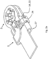
- Fig. 2a shows a second embodiment of the invention in ready-to-use form, which is formed in two parts from contact pin receptacle 2 and electrical connection 3.
- Fig. 2b shows the electrical connection 3 in the state before it is folded and merged with the contact pin receptacle 2. It is designed in a trident shape, with two outer arms 17 and a middle arm 18, each arm carrying a grid 19. The connection end 16 is in turn designed as a sword.
- Fig. 2a shows the bend of the electrical connection 3, which leads to three spaced-apart layers, between which the material of the base 20 of the contact pin receptacle 2 is received.
- the middle arm 18 is thus clamped in the contact pin receptacle 2, whereas the upper and lower arm 17 clamp a position of the contact pin receptacle 2 between themselves and the middle arm.
- This sandwich connection enables optimal use of space for power transmission and at the same time offers a high surface area for heat radiation.
- Two stops 24 can also be seen, which laterally support the upper and lower arms 17 and which are formed in the region of the base 20 by means of stamping and bending.
- Fig. 3 finally shows in the top row several one-piece embodiments of the invention, each with a differently designed connection end 16 of the electrical connection 3 and with the same contact pin receptacle 2.
- the connection ends 16 of the electrical connection 3 are designed here as a sword, as a crimp and as a plug, from the left shown to the right.
- Fig. 3 shows in the lower row several two-part embodiments of the invention, each with a differently designed connection end 16 of the electrical connection 3 in accordance with the aforementioned order.
- the contact pin receptacle 2 is identical to that of the top row. It can be seen that the stops 24 are optional and therefore do not have to occur in every two-part embodiment. The absence of the second connecting device 14 in the region of the opening 6, 7 shows that this is also optional.
- the high-performance contact according to the invention can thus be adapted to many purposes and, thanks to the mobility of the two partial contacts to one another and thanks to the resilient design of the contact arms and their axial extension, enables reliable contact to a contact pin even under harsh operating conditions.
- the high-performance contact is able to conduct large currents safely, even with small overall dimensions, thanks to its sandwich construction.
Landscapes
- Engineering & Computer Science (AREA)
- Manufacturing & Machinery (AREA)
- Coupling Device And Connection With Printed Circuit (AREA)
- Connector Housings Or Holding Contact Members (AREA)
Claims (10)
- Dispositif de mise en contact de puissance (1), présentant un support de broche de contact (2) et au moins un raccordement électrique (3), le support de broche de contact (2) étant constitué en une seule pièce de deux sous-contacts (4, 5) superposés à distance et mobiles l'un par rapport à l'autre, chaque sous-contact (4, 5) présentant une ouverture (6, 7) comportant des bras de contact (8, 9) rentrant dans l'ouverture (6, 7), les deux ouvertures (6, 7) étant disposées coaxialement l'une par rapport à l'autre, les bras de contact (8, 9) d'une ouverture (6, 7) ayant une conformation recourbée vers l'autre ouverture en s'empeignant l'un dans l'autre et les bras de contact (8, 9) présentant, en partant d'un bord d'ouverture (10), d'abord une section s'étendant radialement (11), une section s'étendant axialement (12) suivant la section s'étendant radialement (11) des bras de contact, caractérisé en ce que les sous-contacts (4, 5), en état de fonctionnement, sont réalisés de manière à être mobiles l'un par rapport à l'autre, les deux sous-contacts (4, 5) étant réalisés de manière à être connectés l'un à l'autre au niveau d'une base (20) avec un espacement (A) et les deux sous-contacts (4, 5) étant réalisés de manière à être connectés l'un à l'autre au moyen d'au moins un autre dispositif de connexion (14) et la longueur d'un bras d'enclenchement (22) du dispositif de connexion (14) correspondant à cet espacement (A).
- Dispositif de mise en contact de puissance (1) selon la revendication 1, caractérisé en ce que les ouvertures (6, 7) ont une conformation ronde ou carrée.
- Dispositif de mise en contact de puissance (1) selon la revendication 1 ou 2, caractérisé en ce que les bras de contact (8, 9) présentent un bombement et/ou gaufrage (13).
- Dispositif de mise en contact de puissance (1) selon la revendication 1, 2 ou 3, caractérisé en ce que les deux sous-contacts (4, 5) sont connectés au moyen de deux dispositifs de connexion (14), en particulier de deux dispositifs de connexion à conformation similaire (14) .
- Dispositif de mise en contact de puissance (1) selon une des revendications précédentes, caractérisé en ce que le raccordement électrique (3) forme une seule pièce avec le support de broche de contact (2).
- Dispositif de mise en contact de puissance (1) selon une des revendications précédentes, caractérisé en ce que le raccordement électrique (3) est une pièce connectable au support de broche de contact (2) et présente à cet effet une section de connexion (15).
- Dispositif de mise en contact de puissance (1) selon une des revendications précédentes, caractérisé en ce que le raccordement électrique (3) présente une extrémité de raccordement (16) réalisée en particulier sous forme d'une lame, d'un bouton de contact, d'un sertissage, d'une extrémité brasée, d'un rivet.
- Dispositif de mise en contact de puissance (1) selon la revendication 6 ou 7, caractérisé en ce que la section de connexion (15) du raccordement électrique (3) est réalisée en forme de trident, les deux bras extérieurs (17) du trident ayant une conformation recourbée et étant alignés à distance du dessus et du dessous du bras médian (18).
- Dispositif de mise en contact de puissance (1) selon la revendication 8, caractérisé en ce que la distance allant du bras supérieur (17) et médian (18) et inférieur (17) jusqu'au bras médian (18) correspond à une épaisseur de matériau de l'élément de contact (2) et que l'épaisseur du bras médian (18) correspond à un espacement mutuel entre les deux sous-contacts (4, 5).
- Dispositif de mise en contact de puissance (1) selon une des revendications précédentes, caractérisé en ce que les surfaces de connexion respectives entre les sous-contacts (4, 5) et le raccordement électrique (3) présentent des crantages correspondants (19).
Applications Claiming Priority (2)
| Application Number | Priority Date | Filing Date | Title |
|---|---|---|---|
| DE102016112434.6A DE102016112434A1 (de) | 2016-07-06 | 2016-07-06 | Elektrischer Hochleistungskontakt |
| PCT/EP2017/064831 WO2018007129A1 (fr) | 2016-07-06 | 2017-06-16 | Contact électrique à grande puissance |
Publications (2)
| Publication Number | Publication Date |
|---|---|
| EP3482460A1 EP3482460A1 (fr) | 2019-05-15 |
| EP3482460B1 true EP3482460B1 (fr) | 2020-07-29 |
Family
ID=59091502
Family Applications (1)
| Application Number | Title | Priority Date | Filing Date |
|---|---|---|---|
| EP17731536.3A Active EP3482460B1 (fr) | 2016-07-06 | 2017-06-16 | Contact électrique à grande puissance |
Country Status (7)
| Country | Link |
|---|---|
| US (1) | US10424854B2 (fr) |
| EP (1) | EP3482460B1 (fr) |
| CN (1) | CN109478734B (fr) |
| DE (1) | DE102016112434A1 (fr) |
| ES (2) | ES2821918T3 (fr) |
| MX (1) | MX387274B (fr) |
| WO (1) | WO2018007129A1 (fr) |
Families Citing this family (6)
| Publication number | Priority date | Publication date | Assignee | Title |
|---|---|---|---|---|
| WO2021146641A1 (fr) | 2020-01-17 | 2021-07-22 | The Broad Institute, Inc. | Protéines cas de type ii-d de petite taille et leurs procédés d'utilisation |
| USD978935S1 (en) * | 2020-06-25 | 2023-02-21 | Saint-Gobain Abrasives, Inc. | Floor edger sanding disc |
| USD978937S1 (en) * | 2020-06-25 | 2023-02-21 | Saint-Gobain Abrasives, Inc. | Floor edger sanding disc |
| USD978936S1 (en) * | 2020-06-25 | 2023-02-21 | Saint-Gobain Abrasives, Inc. | Floor edger sanding disc |
| USD978934S1 (en) * | 2020-06-25 | 2023-02-21 | Saint-Gobain Abrasives, Inc. | Floor edger sanding disc |
| US12253102B2 (en) * | 2022-03-07 | 2025-03-18 | Sumitomo Wiring Systems, Ltd. | Clamp assembly configured for vertical tightening |
Family Cites Families (46)
| Publication number | Priority date | Publication date | Assignee | Title |
|---|---|---|---|---|
| US2399957A (en) * | 1942-06-26 | 1946-05-07 | Tinnerman Products Inc | Fastening device |
| USRE22926E (en) * | 1942-06-26 | 1947-10-07 | Fastening device | |
| US2404176A (en) * | 1943-07-15 | 1946-07-16 | Scovill Manufacturing Co | Electric contact snap fastener |
| US3285313A (en) | 1964-08-10 | 1966-11-15 | Essex Wire Corp | Double lockwasher construction |
| US3340494A (en) * | 1965-09-13 | 1967-09-05 | Illinois Tool Works | Electrical connector device |
| US3569919A (en) * | 1969-07-23 | 1971-03-09 | Scovill Manufacturing Co | Snap electrical connector |
| US3796124A (en) * | 1971-11-09 | 1974-03-12 | V Crosa | Clamping system |
| US3980388A (en) * | 1975-10-28 | 1976-09-14 | E. I. Du Pont De Nemours And Company | Battery snap terminal |
| US5183419A (en) * | 1990-12-21 | 1993-02-02 | United Technologies Automotive, Inc. | Battery terminal connector |
| JP2574235Y2 (ja) * | 1992-06-09 | 1998-06-11 | 住友電装株式会社 | バッテリー・ターミナル |
| JP2587000Y2 (ja) * | 1992-09-10 | 1998-12-14 | 住友電装株式会社 | バッテリー・ターミナル |
| EP0601521B1 (fr) * | 1992-12-07 | 2000-03-08 | Sumitomo Wiring Systems, Ltd. | Cosse de batterie |
| JPH0668322U (ja) * | 1993-03-09 | 1994-09-22 | 住友電装株式会社 | バッテリー・ターミナル |
| JPH0688050U (ja) * | 1993-05-31 | 1994-12-22 | 住友電装株式会社 | バッテリー・ターミナル |
| CN1162199A (zh) * | 1995-12-01 | 1997-10-15 | 住友电装株式会社 | 终端接头的安装结构 |
| JP3812000B2 (ja) * | 1996-07-22 | 2006-08-23 | トピーファスナー工業株式会社 | プッシュナットおよびその製造方法 |
| US5733152A (en) * | 1996-10-09 | 1998-03-31 | Royal Die & Stamping Co., Inc. | Battery terminal adaptor and connector |
| US5707192A (en) * | 1996-11-06 | 1998-01-13 | Ford Motor Company | Panel--fastener connector clip |
| US6416340B2 (en) * | 2000-05-04 | 2002-07-09 | Christopher E. Schaefer | Single blade terminal power connector system |
| US6520812B1 (en) * | 2000-08-30 | 2003-02-18 | Antaya Technologies Corporation | Connector terminal with resilient contacts |
| JP3749670B2 (ja) * | 2001-03-13 | 2006-03-01 | 住友電装株式会社 | 組合せ端子金具及び、複数の端子金具の組み付け構造 |
| JP4005867B2 (ja) * | 2002-07-29 | 2007-11-14 | 住友電装株式会社 | 組合せ端子金具 |
| US6817908B2 (en) * | 2002-11-05 | 2004-11-16 | Royal Die & Stamping Co., Inc. | Top clamping battery terminal connector |
| JP4584092B2 (ja) * | 2005-09-20 | 2010-11-17 | 矢崎総業株式会社 | バッテリーターミナル |
| DE102006025078A1 (de) | 2006-05-30 | 2007-12-06 | Hella Kgaa Hueck & Co. | Kontaktelement |
| JP4738323B2 (ja) * | 2006-12-06 | 2011-08-03 | 株式会社パイオラックス | 締結具 |
| ES2555652T3 (es) * | 2007-07-16 | 2016-01-07 | Lg Chem, Ltd. | Elemento de conexión eléctrica para batería secundaria |
| US7806737B2 (en) * | 2008-02-04 | 2010-10-05 | Methode Electronics, Inc. | Stamped beam connector |
| WO2010012872A1 (fr) * | 2008-07-29 | 2010-02-04 | Saint-Gobain Glass France | Connecteur electrique femelle, male et connexion electrique utilisant ce connecteur electrique femelle et/ou male |
| BRPI0823158B1 (pt) * | 2008-10-14 | 2019-01-22 | Mta Spa | braçadeira para um terminal macho |
| US7766706B2 (en) * | 2008-11-17 | 2010-08-03 | J. S. T. Corporation | Female terminal assembly with compression clip |
| JP2012009384A (ja) * | 2010-06-28 | 2012-01-12 | Sumitomo Wiring Syst Ltd | 圧着端子及びボルト締め端子 |
| DE102011005073A1 (de) * | 2011-03-03 | 2012-09-06 | Würth Elektronik Ics Gmbh & Co. Kg | Tandem Multi Fork Einpresspin |
| DE102012002350A1 (de) * | 2011-07-20 | 2013-01-24 | Bals Elektrotechnik Gmbh & Co. Kg | Kontaktelement für eine elektrische Steckverbindervorrichtung |
| US9206807B2 (en) * | 2012-09-06 | 2015-12-08 | Asia Vital Components (China) Co., Ltd. | Preload disk spring, assembly structure thereof, and fan using same |
| JP6078302B2 (ja) * | 2012-11-12 | 2017-02-08 | 矢崎総業株式会社 | 端子金具 |
| CN105229861A (zh) * | 2013-05-21 | 2016-01-06 | 矢崎总业株式会社 | 端子金属配件的连接结构 |
| KR101509987B1 (ko) * | 2013-11-26 | 2015-04-07 | 현대자동차주식회사 | 배터리 단자 체결용 클램프 |
| US9784298B2 (en) * | 2014-01-31 | 2017-10-10 | Reinke Manufacturing Co., Inc. | Theft-resistant cable clamp |
| CN105576182B (zh) * | 2014-11-04 | 2018-09-14 | 矢崎总业株式会社 | 电池端子 |
| ES2794549T3 (es) * | 2014-11-13 | 2020-11-18 | Leukert Gmbh | Dispositivo para la puesta en contacto de potencia |
| US9746018B2 (en) * | 2015-02-02 | 2017-08-29 | Denso International America, Inc. | Speed nut |
| ITUA20164795A1 (it) * | 2016-06-30 | 2017-12-30 | Mta Spa | Morsetto per un terminale maschio. |
| JP6559169B2 (ja) * | 2017-02-03 | 2019-08-14 | 矢崎総業株式会社 | バッテリー端子 |
| US9774110B1 (en) * | 2017-02-10 | 2017-09-26 | Ema-Us, Inc. | Battery post terminal assembly |
| US10008789B1 (en) * | 2017-07-10 | 2018-06-26 | Royal Die & Stamping, Llc | Angled bolt T-bar battery terminal clamp |
-
2016
- 2016-07-06 DE DE102016112434.6A patent/DE102016112434A1/de not_active Withdrawn
-
2017
- 2017-06-16 MX MX2018016111A patent/MX387274B/es unknown
- 2017-06-16 ES ES17731536T patent/ES2821918T3/es active Active
- 2017-06-16 ES ES17064831T patent/ES2664883T6/es active Pending
- 2017-06-16 CN CN201780042186.9A patent/CN109478734B/zh active Active
- 2017-06-16 WO PCT/EP2017/064831 patent/WO2018007129A1/fr not_active Ceased
- 2017-06-16 US US16/313,083 patent/US10424854B2/en active Active
- 2017-06-16 EP EP17731536.3A patent/EP3482460B1/fr active Active
Non-Patent Citations (1)
| Title |
|---|
| None * |
Also Published As
| Publication number | Publication date |
|---|---|
| ES2821918T3 (es) | 2021-04-28 |
| CN109478734B (zh) | 2020-06-16 |
| CN109478734A (zh) | 2019-03-15 |
| US10424854B2 (en) | 2019-09-24 |
| WO2018007129A1 (fr) | 2018-01-11 |
| US20190229444A1 (en) | 2019-07-25 |
| DE102016112434A1 (de) | 2018-01-11 |
| ES2664883T6 (es) | 2018-04-23 |
| MX2018016111A (es) | 2019-05-30 |
| EP3482460A1 (fr) | 2019-05-15 |
| MX387274B (es) | 2025-03-18 |
Similar Documents
| Publication | Publication Date | Title |
|---|---|---|
| EP3482460B1 (fr) | Contact électrique à grande puissance | |
| EP1207588B1 (fr) | Connecteur électrique pour cable plat ou circuit imprimé flexible | |
| EP2810341B1 (fr) | Contact tubulaire pour un connecteur électrique à force d'insertion nulle | |
| EP3446366B1 (fr) | Contact enfichable | |
| EP2131449A1 (fr) | Borne unique | |
| EP2243198B1 (fr) | Connecteur enfichable coaxial coudé | |
| DE102017220778B4 (de) | Kontaktelement | |
| EP1133013B1 (fr) | Pièce de contact pour une connexion électrique ainsi que son procédé de fabrication | |
| EP2852003B1 (fr) | Élément de contact pour un connecteur à fiche | |
| WO2011033128A1 (fr) | Broche à pression à branches multiples | |
| EP3224907B1 (fr) | Connecteur pour films de circuit imprimé flexibles | |
| DE69005126T2 (de) | Elektrischer Steckerstift. | |
| EP3446367B1 (fr) | Contact enfichable | |
| DE102010008536B4 (de) | Elektrische Anschlusseinrichtung | |
| DE2800161C2 (de) | Kontaktelement für den Anschluß eines isolierten Leiters | |
| EP3891846B1 (fr) | Borne de raccordement à ressort | |
| EP2015405A2 (fr) | Connecteur à fiches électrique | |
| EP2779314B1 (fr) | Borne de prise électrique | |
| EP2561582B1 (fr) | Contact électrique | |
| EP3038213B1 (fr) | Borne de connection de cable destinee a serrer au moins un conducteur electrique | |
| DE102012201124B4 (de) | Kontaktelement | |
| EP2551963B1 (fr) | Elément de raccordement électrique | |
| DE102008058203A1 (de) | Steckbuchse für Leiterplatten | |
| EP3123566B1 (fr) | Douille de contact pour prise électrique | |
| EP1763111B1 (fr) | Contact à douille avec au moins deux points de contact dans la direction de connexion |
Legal Events
| Date | Code | Title | Description |
|---|---|---|---|
| STAA | Information on the status of an ep patent application or granted ep patent |
Free format text: STATUS: UNKNOWN |
|
| STAA | Information on the status of an ep patent application or granted ep patent |
Free format text: STATUS: THE INTERNATIONAL PUBLICATION HAS BEEN MADE |
|
| PUAI | Public reference made under article 153(3) epc to a published international application that has entered the european phase |
Free format text: ORIGINAL CODE: 0009012 |
|
| STAA | Information on the status of an ep patent application or granted ep patent |
Free format text: STATUS: REQUEST FOR EXAMINATION WAS MADE |
|
| 17P | Request for examination filed |
Effective date: 20190206 |
|
| AK | Designated contracting states |
Kind code of ref document: A1 Designated state(s): AL AT BE BG CH CY CZ DE DK EE ES FI FR GB GR HR HU IE IS IT LI LT LU LV MC MK MT NL NO PL PT RO RS SE SI SK SM TR |
|
| AX | Request for extension of the european patent |
Extension state: BA ME |
|
| DAV | Request for validation of the european patent (deleted) | ||
| DAX | Request for extension of the european patent (deleted) | ||
| GRAP | Despatch of communication of intention to grant a patent |
Free format text: ORIGINAL CODE: EPIDOSNIGR1 |
|
| STAA | Information on the status of an ep patent application or granted ep patent |
Free format text: STATUS: GRANT OF PATENT IS INTENDED |
|
| INTG | Intention to grant announced |
Effective date: 20200102 |
|
| GRAJ | Information related to disapproval of communication of intention to grant by the applicant or resumption of examination proceedings by the epo deleted |
Free format text: ORIGINAL CODE: EPIDOSDIGR1 |
|
| STAA | Information on the status of an ep patent application or granted ep patent |
Free format text: STATUS: REQUEST FOR EXAMINATION WAS MADE |
|
| GRAP | Despatch of communication of intention to grant a patent |
Free format text: ORIGINAL CODE: EPIDOSNIGR1 |
|
| STAA | Information on the status of an ep patent application or granted ep patent |
Free format text: STATUS: GRANT OF PATENT IS INTENDED |
|
| INTC | Intention to grant announced (deleted) | ||
| GRAS | Grant fee paid |
Free format text: ORIGINAL CODE: EPIDOSNIGR3 |
|
| INTG | Intention to grant announced |
Effective date: 20200508 |
|
| GRAA | (expected) grant |
Free format text: ORIGINAL CODE: 0009210 |
|
| STAA | Information on the status of an ep patent application or granted ep patent |
Free format text: STATUS: THE PATENT HAS BEEN GRANTED |
|
| AK | Designated contracting states |
Kind code of ref document: B1 Designated state(s): AL AT BE BG CH CY CZ DE DK EE ES FI FR GB GR HR HU IE IS IT LI LT LU LV MC MK MT NL NO PL PT RO RS SE SI SK SM TR |
|
| REG | Reference to a national code |
Ref country code: CH Ref legal event code: EP |
|
| REG | Reference to a national code |
Ref country code: AT Ref legal event code: REF Ref document number: 1296886 Country of ref document: AT Kind code of ref document: T Effective date: 20200815 |
|
| REG | Reference to a national code |
Ref country code: IE Ref legal event code: FG4D Free format text: LANGUAGE OF EP DOCUMENT: GERMAN |
|
| REG | Reference to a national code |
Ref country code: DE Ref legal event code: R096 Ref document number: 502017006447 Country of ref document: DE |
|
| REG | Reference to a national code |
Ref country code: LT Ref legal event code: MG4D |
|
| REG | Reference to a national code |
Ref country code: NL Ref legal event code: MP Effective date: 20200729 |
|
| PG25 | Lapsed in a contracting state [announced via postgrant information from national office to epo] |
Ref country code: GR Free format text: LAPSE BECAUSE OF FAILURE TO SUBMIT A TRANSLATION OF THE DESCRIPTION OR TO PAY THE FEE WITHIN THE PRESCRIBED TIME-LIMIT Effective date: 20201030 Ref country code: NO Free format text: LAPSE BECAUSE OF FAILURE TO SUBMIT A TRANSLATION OF THE DESCRIPTION OR TO PAY THE FEE WITHIN THE PRESCRIBED TIME-LIMIT Effective date: 20201029 Ref country code: BG Free format text: LAPSE BECAUSE OF FAILURE TO SUBMIT A TRANSLATION OF THE DESCRIPTION OR TO PAY THE FEE WITHIN THE PRESCRIBED TIME-LIMIT Effective date: 20201029 Ref country code: HR Free format text: LAPSE BECAUSE OF FAILURE TO SUBMIT A TRANSLATION OF THE DESCRIPTION OR TO PAY THE FEE WITHIN THE PRESCRIBED TIME-LIMIT Effective date: 20200729 Ref country code: LT Free format text: LAPSE BECAUSE OF FAILURE TO SUBMIT A TRANSLATION OF THE DESCRIPTION OR TO PAY THE FEE WITHIN THE PRESCRIBED TIME-LIMIT Effective date: 20200729 Ref country code: FI Free format text: LAPSE BECAUSE OF FAILURE TO SUBMIT A TRANSLATION OF THE DESCRIPTION OR TO PAY THE FEE WITHIN THE PRESCRIBED TIME-LIMIT Effective date: 20200729 Ref country code: PT Free format text: LAPSE BECAUSE OF FAILURE TO SUBMIT A TRANSLATION OF THE DESCRIPTION OR TO PAY THE FEE WITHIN THE PRESCRIBED TIME-LIMIT Effective date: 20201130 Ref country code: SE Free format text: LAPSE BECAUSE OF FAILURE TO SUBMIT A TRANSLATION OF THE DESCRIPTION OR TO PAY THE FEE WITHIN THE PRESCRIBED TIME-LIMIT Effective date: 20200729 |
|
| PG25 | Lapsed in a contracting state [announced via postgrant information from national office to epo] |
Ref country code: LV Free format text: LAPSE BECAUSE OF FAILURE TO SUBMIT A TRANSLATION OF THE DESCRIPTION OR TO PAY THE FEE WITHIN THE PRESCRIBED TIME-LIMIT Effective date: 20200729 Ref country code: RS Free format text: LAPSE BECAUSE OF FAILURE TO SUBMIT A TRANSLATION OF THE DESCRIPTION OR TO PAY THE FEE WITHIN THE PRESCRIBED TIME-LIMIT Effective date: 20200729 Ref country code: PL Free format text: LAPSE BECAUSE OF FAILURE TO SUBMIT A TRANSLATION OF THE DESCRIPTION OR TO PAY THE FEE WITHIN THE PRESCRIBED TIME-LIMIT Effective date: 20200729 Ref country code: IS Free format text: LAPSE BECAUSE OF FAILURE TO SUBMIT A TRANSLATION OF THE DESCRIPTION OR TO PAY THE FEE WITHIN THE PRESCRIBED TIME-LIMIT Effective date: 20201129 |
|
| PG25 | Lapsed in a contracting state [announced via postgrant information from national office to epo] |
Ref country code: NL Free format text: LAPSE BECAUSE OF FAILURE TO SUBMIT A TRANSLATION OF THE DESCRIPTION OR TO PAY THE FEE WITHIN THE PRESCRIBED TIME-LIMIT Effective date: 20200729 |
|
| REG | Reference to a national code |
Ref country code: ES Ref legal event code: FG2A Ref document number: 2821918 Country of ref document: ES Kind code of ref document: T3 Effective date: 20210428 |
|
| PG25 | Lapsed in a contracting state [announced via postgrant information from national office to epo] |
Ref country code: RO Free format text: LAPSE BECAUSE OF FAILURE TO SUBMIT A TRANSLATION OF THE DESCRIPTION OR TO PAY THE FEE WITHIN THE PRESCRIBED TIME-LIMIT Effective date: 20200729 Ref country code: CZ Free format text: LAPSE BECAUSE OF FAILURE TO SUBMIT A TRANSLATION OF THE DESCRIPTION OR TO PAY THE FEE WITHIN THE PRESCRIBED TIME-LIMIT Effective date: 20200729 Ref country code: DK Free format text: LAPSE BECAUSE OF FAILURE TO SUBMIT A TRANSLATION OF THE DESCRIPTION OR TO PAY THE FEE WITHIN THE PRESCRIBED TIME-LIMIT Effective date: 20200729 Ref country code: SM Free format text: LAPSE BECAUSE OF FAILURE TO SUBMIT A TRANSLATION OF THE DESCRIPTION OR TO PAY THE FEE WITHIN THE PRESCRIBED TIME-LIMIT Effective date: 20200729 Ref country code: EE Free format text: LAPSE BECAUSE OF FAILURE TO SUBMIT A TRANSLATION OF THE DESCRIPTION OR TO PAY THE FEE WITHIN THE PRESCRIBED TIME-LIMIT Effective date: 20200729 |
|
| REG | Reference to a national code |
Ref country code: DE Ref legal event code: R097 Ref document number: 502017006447 Country of ref document: DE |
|
| PG25 | Lapsed in a contracting state [announced via postgrant information from national office to epo] |
Ref country code: AL Free format text: LAPSE BECAUSE OF FAILURE TO SUBMIT A TRANSLATION OF THE DESCRIPTION OR TO PAY THE FEE WITHIN THE PRESCRIBED TIME-LIMIT Effective date: 20200729 |
|
| PLBE | No opposition filed within time limit |
Free format text: ORIGINAL CODE: 0009261 |
|
| STAA | Information on the status of an ep patent application or granted ep patent |
Free format text: STATUS: NO OPPOSITION FILED WITHIN TIME LIMIT |
|
| PG25 | Lapsed in a contracting state [announced via postgrant information from national office to epo] |
Ref country code: SK Free format text: LAPSE BECAUSE OF FAILURE TO SUBMIT A TRANSLATION OF THE DESCRIPTION OR TO PAY THE FEE WITHIN THE PRESCRIBED TIME-LIMIT Effective date: 20200729 |
|
| 26N | No opposition filed |
Effective date: 20210430 |
|
| PG25 | Lapsed in a contracting state [announced via postgrant information from national office to epo] |
Ref country code: SI Free format text: LAPSE BECAUSE OF FAILURE TO SUBMIT A TRANSLATION OF THE DESCRIPTION OR TO PAY THE FEE WITHIN THE PRESCRIBED TIME-LIMIT Effective date: 20200729 |
|
| PG25 | Lapsed in a contracting state [announced via postgrant information from national office to epo] |
Ref country code: MC Free format text: LAPSE BECAUSE OF FAILURE TO SUBMIT A TRANSLATION OF THE DESCRIPTION OR TO PAY THE FEE WITHIN THE PRESCRIBED TIME-LIMIT Effective date: 20200729 |
|
| REG | Reference to a national code |
Ref country code: CH Ref legal event code: PL |
|
| REG | Reference to a national code |
Ref country code: BE Ref legal event code: MM Effective date: 20210630 |
|
| PG25 | Lapsed in a contracting state [announced via postgrant information from national office to epo] |
Ref country code: LU Free format text: LAPSE BECAUSE OF NON-PAYMENT OF DUE FEES Effective date: 20210616 |
|
| PG25 | Lapsed in a contracting state [announced via postgrant information from national office to epo] |
Ref country code: LI Free format text: LAPSE BECAUSE OF NON-PAYMENT OF DUE FEES Effective date: 20210630 Ref country code: IE Free format text: LAPSE BECAUSE OF NON-PAYMENT OF DUE FEES Effective date: 20210616 Ref country code: CH Free format text: LAPSE BECAUSE OF NON-PAYMENT OF DUE FEES Effective date: 20210630 |
|
| PG25 | Lapsed in a contracting state [announced via postgrant information from national office to epo] |
Ref country code: BE Free format text: LAPSE BECAUSE OF NON-PAYMENT OF DUE FEES Effective date: 20210630 |
|
| PG25 | Lapsed in a contracting state [announced via postgrant information from national office to epo] |
Ref country code: CY Free format text: LAPSE BECAUSE OF FAILURE TO SUBMIT A TRANSLATION OF THE DESCRIPTION OR TO PAY THE FEE WITHIN THE PRESCRIBED TIME-LIMIT Effective date: 20200729 |
|
| PG25 | Lapsed in a contracting state [announced via postgrant information from national office to epo] |
Ref country code: HU Free format text: LAPSE BECAUSE OF FAILURE TO SUBMIT A TRANSLATION OF THE DESCRIPTION OR TO PAY THE FEE WITHIN THE PRESCRIBED TIME-LIMIT; INVALID AB INITIO Effective date: 20170616 |
|
| REG | Reference to a national code |
Ref country code: AT Ref legal event code: MM01 Ref document number: 1296886 Country of ref document: AT Kind code of ref document: T Effective date: 20220616 |
|
| P01 | Opt-out of the competence of the unified patent court (upc) registered |
Effective date: 20230724 |
|
| PG25 | Lapsed in a contracting state [announced via postgrant information from national office to epo] |
Ref country code: AT Free format text: LAPSE BECAUSE OF NON-PAYMENT OF DUE FEES Effective date: 20220616 |
|
| PG25 | Lapsed in a contracting state [announced via postgrant information from national office to epo] |
Ref country code: MK Free format text: LAPSE BECAUSE OF FAILURE TO SUBMIT A TRANSLATION OF THE DESCRIPTION OR TO PAY THE FEE WITHIN THE PRESCRIBED TIME-LIMIT Effective date: 20200729 |
|
| PG25 | Lapsed in a contracting state [announced via postgrant information from national office to epo] |
Ref country code: TR Free format text: LAPSE BECAUSE OF FAILURE TO SUBMIT A TRANSLATION OF THE DESCRIPTION OR TO PAY THE FEE WITHIN THE PRESCRIBED TIME-LIMIT Effective date: 20200729 |
|
| PG25 | Lapsed in a contracting state [announced via postgrant information from national office to epo] |
Ref country code: MT Free format text: LAPSE BECAUSE OF FAILURE TO SUBMIT A TRANSLATION OF THE DESCRIPTION OR TO PAY THE FEE WITHIN THE PRESCRIBED TIME-LIMIT Effective date: 20200729 |
|
| PGFP | Annual fee paid to national office [announced via postgrant information from national office to epo] |
Ref country code: DE Payment date: 20250618 Year of fee payment: 9 |
|
| PGFP | Annual fee paid to national office [announced via postgrant information from national office to epo] |
Ref country code: GB Payment date: 20250620 Year of fee payment: 9 |
|
| PGFP | Annual fee paid to national office [announced via postgrant information from national office to epo] |
Ref country code: FR Payment date: 20250624 Year of fee payment: 9 |
|
| PGFP | Annual fee paid to national office [announced via postgrant information from national office to epo] |
Ref country code: ES Payment date: 20250718 Year of fee payment: 9 |
|
| PGFP | Annual fee paid to national office [announced via postgrant information from national office to epo] |
Ref country code: IT Payment date: 20250630 Year of fee payment: 9 |