EP3482845A1 - Formteil, giessform und verfahren zum formen eines grünlings - Google Patents
Formteil, giessform und verfahren zum formen eines grünlings Download PDFInfo
- Publication number
- EP3482845A1 EP3482845A1 EP17201424.3A EP17201424A EP3482845A1 EP 3482845 A1 EP3482845 A1 EP 3482845A1 EP 17201424 A EP17201424 A EP 17201424A EP 3482845 A1 EP3482845 A1 EP 3482845A1
- Authority
- EP
- European Patent Office
- Prior art keywords
- molding
- molded part
- shell
- mold
- flange
- Prior art date
- Legal status (The legal status is an assumption and is not a legal conclusion. Google has not performed a legal analysis and makes no representation as to the accuracy of the status listed.)
- Granted
Links
Images



Classifications
-
- B—PERFORMING OPERATIONS; TRANSPORTING
- B28—WORKING CEMENT, CLAY, OR STONE
- B28B—SHAPING CLAY OR OTHER CERAMIC COMPOSITIONS; SHAPING SLAG; SHAPING MIXTURES CONTAINING CEMENTITIOUS MATERIAL, e.g. PLASTER
- B28B1/00—Producing shaped prefabricated articles from the material
- B28B1/26—Producing shaped prefabricated articles from the material by slip-casting, i.e. by casting a suspension or dispersion of the material in a liquid-absorbent or porous mould, the liquid being allowed to soak into or pass through the walls of the mould; Moulds therefor ; specially for manufacturing articles starting from a ceramic slip; Moulds therefor
- B28B1/261—Moulds therefor
- B28B1/262—Mould materials; Manufacture of moulds or parts thereof
-
- B—PERFORMING OPERATIONS; TRANSPORTING
- B22—CASTING; POWDER METALLURGY
- B22C—FOUNDRY MOULDING
- B22C9/00—Moulds or cores; Moulding processes
-
- B—PERFORMING OPERATIONS; TRANSPORTING
- B28—WORKING CEMENT, CLAY, OR STONE
- B28B—SHAPING CLAY OR OTHER CERAMIC COMPOSITIONS; SHAPING SLAG; SHAPING MIXTURES CONTAINING CEMENTITIOUS MATERIAL, e.g. PLASTER
- B28B1/00—Producing shaped prefabricated articles from the material
- B28B1/26—Producing shaped prefabricated articles from the material by slip-casting, i.e. by casting a suspension or dispersion of the material in a liquid-absorbent or porous mould, the liquid being allowed to soak into or pass through the walls of the mould; Moulds therefor ; specially for manufacturing articles starting from a ceramic slip; Moulds therefor
- B28B1/265—Producing shaped prefabricated articles from the material by slip-casting, i.e. by casting a suspension or dispersion of the material in a liquid-absorbent or porous mould, the liquid being allowed to soak into or pass through the walls of the mould; Moulds therefor ; specially for manufacturing articles starting from a ceramic slip; Moulds therefor pressure being applied on the slip in the filled mould or on the moulded article in the mould, e.g. pneumatically, by compressing slip in a closed mould
-
- B—PERFORMING OPERATIONS; TRANSPORTING
- B28—WORKING CEMENT, CLAY, OR STONE
- B28B—SHAPING CLAY OR OTHER CERAMIC COMPOSITIONS; SHAPING SLAG; SHAPING MIXTURES CONTAINING CEMENTITIOUS MATERIAL, e.g. PLASTER
- B28B1/00—Producing shaped prefabricated articles from the material
- B28B1/26—Producing shaped prefabricated articles from the material by slip-casting, i.e. by casting a suspension or dispersion of the material in a liquid-absorbent or porous mould, the liquid being allowed to soak into or pass through the walls of the mould; Moulds therefor ; specially for manufacturing articles starting from a ceramic slip; Moulds therefor
- B28B1/265—Producing shaped prefabricated articles from the material by slip-casting, i.e. by casting a suspension or dispersion of the material in a liquid-absorbent or porous mould, the liquid being allowed to soak into or pass through the walls of the mould; Moulds therefor ; specially for manufacturing articles starting from a ceramic slip; Moulds therefor pressure being applied on the slip in the filled mould or on the moulded article in the mould, e.g. pneumatically, by compressing slip in a closed mould
- B28B1/266—Means for counteracting the pressure being applied on the slip or on the moulded article in the mould, e.g. means for clamping the moulds parts together in a frame-like structure
-
- B—PERFORMING OPERATIONS; TRANSPORTING
- B28—WORKING CEMENT, CLAY, OR STONE
- B28B—SHAPING CLAY OR OTHER CERAMIC COMPOSITIONS; SHAPING SLAG; SHAPING MIXTURES CONTAINING CEMENTITIOUS MATERIAL, e.g. PLASTER
- B28B7/00—Moulds; Cores; Mandrels
- B28B7/40—Moulds; Cores; Mandrels characterised by means for modifying the properties of the moulding material
- B28B7/46—Moulds; Cores; Mandrels characterised by means for modifying the properties of the moulding material for humidifying or dehumidifying
Definitions
- the present invention relates to a molding for a mold, a mold having at least one molding and a method for molding a green compact.
- Such a mold is for example from the EP 3 162 521 A1 known.
- the EP 3 162 521 A1 shows a mold in general form.
- the casting mold has a first upper molding and a second lower molding.
- the moldings are inserted between two compacts and brought together by them. Between the moldings, a mold space is formed.
- the mold parts each have a porous or permeable edge layer on their surface facing the mold space. Air and fluid can be diverted through this surface layer. It is conceivable that the mold has only one molding or more than two moldings.
- the lower molding of the mold from the EP 3 162 521 A1 has an outlet for discharging water or air. This outlet line is connected to the porous layer.
- the mold and the moldings from the EP 3 162 521 A1 are relatively large and heavy and thus relatively difficult to handle.
- the dewatering of the slip, which is filled between the moldings uneven.
- a molding for a mold is to be made available, which allows a uniform dewatering of the molding.
- a molded part is to be made available, which allows a simple production of moldings and / or green bodies.
- a corresponding method is to be made available.
- An inventive molding for a mold in particular for a multi-part mold, comprises at least one shell for casting a particular ceramic product. At one edge of this molding a flange is arranged for sealing engagement with a sealing surface and in particular for sealing contact with a second molded part.
- the shell has a first permeability to a fluid and the flange has a second permeability to the fluid. The second permeability is less than the first permeability.
- the permeability is defined as the volume of a fluid which can be passed through a solid per hour, per square decimeter and per pressure: l / (h * dm 2 * bar).
- Different permeabilities for the shell and the flange make it possible to specifically control the fluid flow within the molded part.
- the flange is cast on the shell, in particular made in one piece with the shell.
- the flange and the shell are thus an integral part of the molding and thus subject to the same loss.
- the production is facilitated and the molding has no unnecessary joints.
- the shell and the flange are made substantially of the same material.
- the material is preferably a plastic, and more preferably PMMA.
- the production of the same material improves the properties of the molded part.
- the material properties are the same for the entire molded part.
- the shell of the molding preferably has a permeability of at least 10 l / (h * dm 2 * bar). Alternatively or additionally, the permeability of the flange is at most 1 l / (h * dm 2 * bar).
- the molded part may have a seal, which is preferably designed as a circumferential seal. This seal is preferably arranged in or on the flange.
- a gasket also makes it possible to make the flange with a greater tolerance since the sealing effect can be provided via the gasket and not via the flange.
- the flange may preferably have a recess in which the seal is inserted. Particularly preferably, the seal is cast in the flange.
- the recess may have an undercut.
- the present molding can be constructed in several parts and in particular have an inner and an outer layer.
- inner layer means that it faces the mold space and thus the subsequent green body.
- Another aspect of the present invention relates to a mold having at least one and preferably two moldings as described herein.
- a mold allows the production of particular ceramic products and the series production of a desired geometry.
- Another aspect of the invention relates to a molded part, in particular a molded part as described herein, wherein in the molding at least one drainage channel is provided.
- the drainage channel has at least one drainage channel end, via which liquids can be discharged by means of a discharge line.
- the molded part has a releasable coupling for detachably connecting the drainage channel end to the discharge line.
- the drainage channel end is formed as a coupling and cooperates with a corresponding coupling with a pressing cylinder.
- a separate packing for displacing media such as water, is provided which fills the mold, wherein the coupling or the drainage channel end extends through the packing to the Anpresszylinder.
- the releasable coupling can be arranged in a central region of the molded part and in particular in a region at or adjacent to the center of mass of the molded part.
- This range is preferably selected such that moments of inertia about an axis of the coupling can be minimized.
- the releasable coupling is preferably designed such that it can be gripped by a robot.
- the coupling not only assumes the function of discharging the water but also the function of providing an element for gripping and handling of the molding.
- the robot grips the mold on a coupling as described herein.
- the coupling may extend, for example, from the molded part through the filling body, so that when the coupling is gripped by the robot, at least part of the casting mold, such as a filling body, is lifted off together with the molded part.
- at least part of the casting mold such as a filling body
- Another aspect of the invention relates to a molding for a mold, in particular a molded part as described herein, wherein the mold part has a shell with a molding surface for molding a particular ceramic product.
- the shell is at least partially fluid-permeable.
- In the shell channels are provided, so that the molding surface with a medium and in particular with air and / or water can be acted upon.
- the molded part has at least one media connection for connecting the channels to a media source and in particular to a compressed air source.
- channels mean separately formed channels and not the fluid connections within the shell, which are formed by the pores.
- the channels are typically formed as tubular connections.
- the air can flow through the pores of the molding surface up to the molded part located in the molding and evenly detached from the molding surface without the molding deformed.
- the channels are preferably arranged such that each point of the molding surface is spaced from at least one channel which is smaller than 50mm and in particular smaller than 30mm.
- the molded part surface is the surface facing the mold cavity, i. the surface that is in contact with the mass or slurry during molding of the molding.
- the channels extend beyond the shell to a lateral flange.
- the media connection is preferably arranged on the flange.
- the arrangement of the media termination on the flange facilitates the decoupling of an air supply line, namely the media source.
- the arrangement of the media outflow on the flange allows a flow through the molded part to the drainage canal end.
- the channels extend substantially radially from a central region of the shell to the flange.
- the channels may be arranged such that they do not extend to the molding surface of the shell. That is, the channels are arranged within the molding and have a closed cross-section.
- the channels are formed as depressions in a surface and the closed cross-section forms only when the molding is arranged in the mold. A closed wall of the channels then results from the mold and the molding.
- the channels open in the flange in a circumferential collecting channel, which is connected to the media connection.
- the molded part located in the molding is thereby applied uniformly with compressed air, a uniform detachment of the molding from the molding is thus possible.
- the molded part has a porous shell and a filler for displacing an unnecessary cavity.
- the filler and the shell are connected to each other with a detachable connection.
- the FIG. 1 shows a cross section through a mold 100.
- the mold 100 has two mold parts 1a and 1b, which are arranged one above the other in the concrete embodiment.
- a seal 14 is arranged in the present figure at the top molding 1a.
- the seal 14 is located in a flange 12 of the molding 1a.
- the molded part 1a also has a shell 11 which is connected to the flange 12.
- the second mold part 1b is formed corresponding to the first mold part 1a with the difference that the second molded part 1b has no seal. Therefore, only the structure of one of the mold parts 1a or 1b will be explained below.
- the molded part 1a has a shell 11 and a flange 12, wherein a seal 14 is located in the flange 12.
- the shell 12 In the shell 12 are drainage channels 15, which are connected to a drainage channel end 151.
- the drainage channel end 151 is at the same time designed as a coupling 16.
- a molding 3 Within a mold space between the moldings 1 is a molding 3, which later becomes a green body 31, as soon as the molding is dewatered via the drainage channels 15.
- the shell 12 is porous and has a molding surface 121 which faces the molding 3.
- Water can thus diffuse from the molding 3 through the porous shell into the drainage channels 15. It collects in the drainage channels 15 and can then be discharged via the coupling 16. To accelerate this process, a negative pressure can be generated at the coupling 16, that is at the drainage channel end 151.
- the drainage channels 15 are star-shaped with the center at the coupling 16 is formed (see FIG. 2 ). They open together in a collecting channel 18.
- the collecting channel 18 is formed as a circumferential annular channel in the flange 12. In the present case, the collecting channel 18 and the drainage channel 15 simultaneously form an air channel 17.
- a separate media connection ie a separate air supply or air discharge line, on the flange. This can extend through the flange 12 into the annular channel 18. It is also conceivable to provide a separate to the drainage channels 15 media channel network. This may be formed according to the drainage channel network and, for example, each adjacent or in a parallel plane to the drainage channels 15 are located. Media port 171 and drainage channel end 151 may be formed separately.
- the molded parts 1 a, 1 b are arranged within a frame 4.
- the cavities that form between the frame 4 and the mold parts 1 a, 1 b are each filled with a filling body 41.
- the packing 41 are each formed as a separate element.
- the fillers 41 can be connected with a detachable connection with the respective molded part 1a or 1b.
- the FIG. 2 shows a schematic plan view of the molding 1a from the FIG. 1 ,
- the molded part 1a essentially has a coupling 16 centrally.
- the drainage channels 15 are arranged in the shell 11 of the molding 1a.
- These drainage channels 15 extend from the coupling 16 to the flange 12 of the molded part 1 a.
- the drainage channels 15 are arranged substantially in a star shape, wherein the drainage channels 15, the farther they are from the clutch 16, branch.
- the maximum distances between the individual drainage channels are limited. That is, an inside of the molding, namely a molding surface 121 (see FIG. 1 ) is spaced from a drainage channel 15 at any point on the surface at most a certain distance (and here 50mm).
- channels are shown only in about a quarter of the shell. Of course, further drainage channels 15 also extend in the others three quarters of the shell 11.
- the drainage channels 15 open into a circumferential collecting channel 18 which is arranged in the flange 12 of the molded part 1a (see FIG. 1 and 3k ).
- At least two centering elements (in the concrete embodiment six) 19 are arranged on the periphery of the molded part 1a, which are presently designed as holes through which clamping screws can extend, for example, in the assembled state.
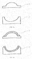
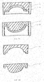
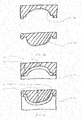
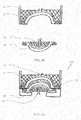
- FIGS. 3a to 3o show a method for producing a molding 1a, 1b (see FIG. 1 ) as well as a molding, respectively a green body 31 (see FIG. 1 and FIG. 3o ).
- FIG. 3a each shows a casting device 20 and 20 ', which are made for example of plaster.
- the casting devices 20 and 20 ' form the basis for manufacturing the moldings.
- the Figure 3c shows the production of shell cores 23 and 23 '.
- a box was built and the cavity filled with plaster.
- These shell pots 23 and 23 ' harden and can, as in 3d figure shown to be removed from the mold after curing.
- a release agent 25, 25 'applied to the pot cores 23 and 23' is then step ( FIG. 3e ).
- the shell cores are again with the corresponding Giess wornen 20, 20 '(see FIG. 3a ) locked.
- the shell cores 23 and 23 'sprue openings 27, 27' and vent openings 26, 26 ' are introduced.
- the respective shell core 23 and 23 ' is firmly connected to the respective casting device 20 and 20'.
- 27 'porous mold material is introduced ( FIG. 3g ).
- the cavity which is located between the shell cores 23 and 23 'and the respective casting device 20, 20', a respective shell 11, 11 'of the subsequent molded part 1a and 1b is formed.
- FIG. 3k are the shells 11, 11 'from the FIG. 3a shown without hatching so that drainage and / or ventilation channels 15, 17 are visible in the shell.
- FIG. 3k is also a cross section through a drainage / ventilation duct 15, 17 shown. In the present case, these channels are substantially U-shaped. After milling these channels 15, 17 they are filled with a Aussparmaterial 28.
- a further step is in at least one of the substantially finished here trained shells 1a or 1b (see FIG. 3f ) has a sealing groove 32 milled.
- the seal groove 32 is in the Figure 3m shown as detail excerpt.
- This seal groove has an undercut in the concrete embodiment, ie in the bottom of the groove, this is wider than at its open end.
- a seal 14 made of silicone is poured into this sealing groove 32, which is fixed by the undercut of the sealing groove 32.
- the mold parts 1a and 1b are separated from each other (see FIG. 3n ) and, if necessary, placed in a suitable box.
- the resulting voids are filled with a filler having a density less than 5kg / dm 3 , which forms a packing 41.
- the filler body can be designed so that it is detachably connected to the respective molded part 1a and 1b or is connectable. In this case, screw and / or snap connections can be provided.
- the mold parts 1a and 1b can be assembled in a mold 100 (see FIG. 3o , And also FIG. 1 ).
- the material to be cast can be introduced through the coupling in a cavity which is formed between the molded parts 1a and 1b. Within this cavity is a molded product, respectively a green body.
- the molding 1a may be used as part of the casting mold 100 (see FIGS. 3o and 3n ) with a robot on the coupling 16 ( Figure 3l ). It can simultaneously by the in the FIG. 3o Air is blown on the lower mold part 1b arranged coupling 16 'and at the clutch 16 located on the upper mold part 1a a negative pressure is generated. The negative pressure holds the molded article 31 on the molded part 1a, while the introduction of air to the coupling 16 'releases the molded article 31 from the molded article 1b. Following the molding can be solved by the molding 1a. For this purpose, an overpressure must be generated on the molded part 1a.
Landscapes
- Engineering & Computer Science (AREA)
- Chemical & Material Sciences (AREA)
- Ceramic Engineering (AREA)
- Mechanical Engineering (AREA)
- Manufacturing & Machinery (AREA)
- Dispersion Chemistry (AREA)
- Producing Shaped Articles From Materials (AREA)
- Moulds For Moulding Plastics Or The Like (AREA)
Abstract
Description
- Die vorliegende Erfindung bezieht sich auf ein Formteil für eine Giessform, eine Giessform mit mindestens einen Formteil sowie ein Verfahren zum Formen eines Grünlings.
- Aus dem Stand der Technik sind verschiedene Giessformen und Formteile für Giessformen bekannt. Eine derartige Giessform ist beispielsweise aus der
EP 3 162 521 A1 bekannt. DieEP 3 162 521 A1 zeigt eine Giessform in allgemeiner Form. Die Giessform weist ein erstes oberes Formteil und ein zweites unteres Formteil auf. Die Formteile werden zwischen zwei Presskörper eingelegt und durch diese zusammengerückt. Zwischen den Formteilen bildet sich ein Formraum. - Typischerweise weisen die Formteile an ihrer dem Formraum zugewandten Fläche jeweils eine poröse bzw. permeable Randschicht auf. Durch diese Randschicht ist Luft und Flüssigkeit ableitbar. Dabei ist es vorstellbar, dass die Giessform nur ein Formteil oder mehr als zwei Formteile aufweist.
- Das untere Formteil der Giessform aus der
EP 3 162 521 A1 weist eine Auslassleitung zum Auslassen von Wasser oder Luft auf. Diese Auslassleitung ist mit der porösen Schicht verbunden. - Die Giessform und die Formteile aus der
EP 3 162 521 A1 sind relativ gross und schwer und dadurch relativ schwierig handzuhaben. Zudem ist das Entwässern des Schlickers, der zwischen die Formteile eingefüllt wird, ungleichmässig. - Es ist daher Aufgabe der Erfindung diese und weitere Nachteile des Standes der Technik zu beheben. Insbesondere soll ein Formteil für eine Giessform zur Verfügung gestellt werden, welches ein gleichmässiges Entwässern des Formlings ermöglicht. Zudem soll insbesondere ein Formteil zur Verfügung gestellt werden, welches eine einfache Fertigung von Formlingen und/oder Grünlingen ermöglicht. Insbesondere soll ein entsprechendes Verfahren zur Verfügung gestellt werden.
- Diese und weitere Aufgaben werden durch die in den unabhängigen Patentansprüchen definierten Vorrichtungen und Verfahren gelöst. Weitere Ausführungsformen ergeben sich aus den abhängigen Patentansprüchen.
- Ein erfindungsgemässes Formteil für eine Giessform, insbesondere für eine mehrteilige Giessform, umfasst mindestens eine Schale zum Giessen eines insbesondere keramischen Produkts. An einem Rand dieses Formteils ist ein Flansch zur dichtenden Anlage an eine Dichtfläche und insbesondere zur dichtenden Anlage an ein zweites Formteil angeordnet. Die Schale weist eine erste Durchlässigkeit für ein Fluid und der Flansch eine zweite Durchlässigkeit für das Fluid auf. Die zweite Durchlässigkeit ist kleiner als die erste Durchlässigkeit.
- Die Durchlässigkeit ist dabei definiert als Volumen eines Fluids welches pro Stunde, pro Quadratdezimeter und pro Druck durch einen Festkörper geleitet werden kann: l/(h*dm2*bar)..
- Unterschiedliche Durchlässigkeiten für die Schale und den Flansch ermöglichen es, den Fluidfluss innerhalb des Formteiles spezifisch zu steuern. Das heisst vorliegend insbesondere, dass ein Fluid, welcher sich in einem Formraum befindet, über die Schale des Formteils und nicht über den Flansch des Formteils abgeführt wird. Der Abführstrom ist damit gerichtet.
- Vorzugsweise ist der Flansch an der Schale angegossen, insbesondere einstückig mit der Schale gefertigt.
- Der Flansch und die Schale sind damit integraler Bestandteil des Formteils und damit gleichem Schwund unterworfen. Die Fertigung ist erleichtert und das Formteil weist keine unnötigen Trennfugen auf.
- Vorzugsweise sind die Schale und der Flansch im Wesentlichen aus dem gleichen Material gefertigt. Das Material ist vorzugsweise ein Kunststoff und besonders bevorzugt PMMA.
- Die Fertigung aus gleichem Material verbessert die Eigenschaften des Formteiles. Die Werkstoffeigenschaften sind für das gesamte Formteil gleich.
- Die Schale des Formteils weist vorzugsweise eine Durchlässigkeit von mindestens 10 l/(h*dm2*bar) auf. Alternativ oder zusätzlich ist die Durchlässigkeit des Flansches maximal 1 l/(h*dm2*bar).
- Das Formteil kann eine Dichtung aufweisen, welche vorzugsweise als umlaufende Dichtung ausgebildet ist. Diese Dichtung ist vorzugsweise in oder am Flansch angeordnet.
- Dies ermöglicht es, das Formteil bei der Anlage auf eine Dichtfläche abzudichten, insbesondere den Formraum gegenüber der Umgebung zu verschliessen und/oder abzudichten.
- Eine Dichtung ermöglicht es ebenfalls, den Flansch mit einer grösseren Toleranz zu fertigen, da die Dichtwirkung über die Dichtung und nicht über den Flansch bereitgestellt werden kann.
- Der Flansch kann vorzugsweise eine Vertiefung aufweisen, in welcher die Dichtung eingesetzt ist. Besonders bevorzugt ist die Dichtung im Flansch eingegossen.
- Damit ist die Dichtung im Flansch gesichert und gegen Verlust geschützt.
- Die Vertiefung kann einen Hinterschnitt aufweisen.
- Die Sicherung gegen Verlust ist dadurch erhöht.
- Das vorliegende Formteil kann mehrteilig aufgebaut sein und insbesondere eine innere und eine äussere Schicht aufweisen.
- Dabei bedeutet innere Schicht, dass diese dem Formraum und damit dem späteren Grünling zugewandt ist.
- Ein weiterer Aspekt der vorliegenden Erfindung betrifft eine Giessform mit mindestens einem und vorzugsweise zwei Formteilen wie vorliegend beschrieben. Eine derartige Giessform ermöglicht die Herstellung von insbesondere keramischen Produkten und die Serienfertigung einer gewünschten Geometrie.
- Ein weiterer Aspekt der Erfindung betrifft ein Formteil, insbesondere ein Formteil wie vorliegend beschrieben, wobei in dem Formteil mindestens ein Entwässerungskanal vorgesehen ist. Der Entwässerungskanal weist mindestens ein Entwässerungskanalende auf, über welches Flüssigkeiten mittels einer Abführleitung abführbar sind. Das Formteil weist eine lösbare Kupplung zum lösbar Verbinden des Entwässerungskanalendes mit der Abführleitung auf.
- Dies ermöglicht das individuelle An- und Abkoppeln der Abführleitung. Insbesondere ist es vorstellbar, dass das Entwässerungskanalende als Kupplung ausgebildet wird und mit einer entsprechenden Kupplung mit einem Presszylinder zusammenwirkt.
- Dies ermöglicht es, unmittelbar mit dem Anlegen des Presszylinders an das Formteil ebenfalls die Abführleitung anzukoppeln. Das separate Ankoppeln der Abführleitung entfällt, zwei Schritte sind in einem Schritt kombiniert.
- Dabei kann vorgesehen sein, dass zwischen dem Formteil und dem Anpresszylinder ein separater Füllkörper zum Verdrängen von Medien, beispielsweise Wasser, vorgesehen ist, welcher die Giessform ausfüllt, wobei sich die Kupplung oder das Entwässerungskanalende durch den Füllkörper bis zum Anpresszylinder erstreckt.
- Die lösbare Kupplung kann dabei in einen zentralen Bereich des Formteils und insbesondere in einem Bereich an oder benachbart zum Massenschwerpunkt des Formteils angeordnet sein.
- Dieser Bereich ist vorzugsweise derart gewählt, dass Trägheitsmomente um eine Achse der Kupplung minimiert werden können.
- Die lösbare Kupplung ist vorzugsweise derart ausgestaltet, dass sie mit einem Roboter greifbar ist.
- Dies ermöglicht es, das Formteil aus der Gussform abzuheben, ohne zusätzliche Elemente am Formteil anbringen zu müssen. Die Kupplung übernimmt dabei nicht nur die Funktion des Abführens des Wassers sondern ebenfalls die Funktion der Bereitstellung eines Elementes zum Greifen und zum Handling des Formteils.
- Es kann dabei vorgesehen sein, an der Kupplung eine zusätzliche Greifkontur auszubilden oder allenfalls eine zweite Blindkupplung vorzusehen, die ein Verdrehen des Formteils in einem Greifarm des Roboters verhindert.
- Ein weiterer Aspekt der Erfindung betrifft ein Verfahren zum Formen eines Grünlings umfassend die Schritte
- Bereitstellen eines Formteils mit mindestens einem Entwässerungskanal der mindestens ein Entwässerungskanalende aufweist, insbesondere mit einem wie vorliegend beschriebenen Formteil;
- Befüllen des Formteils mit einer zu giessenden Masse;
- Aufbauen eines Druckes auf das Formteil zum Erzeugen eines Formlings;
- Entwässern des Formlings zum Erzeugen eines Grünlings durch Abführen von Flüssigkeit aus dem Formling durch den mindestens einen Entwässerungskanal und eine Abführleitung;
- Nach dem Entwässern, Entkoppeln der Abführleitung vom Entwässerungskanalende;
- Ergreifen der Giessform oder des Formteils mit einem Roboter zum Öffnen der Giessform und/oder Entformen des Grünlings.
- Vorzugsweise ergreift der Roboter die Giessform an einer wie vorliegend beschriebenen Kupplung.
- Die Kupplung kann sich beispielsweise vom Formteil durch den Füllkörper erstrecken, so, dass beim Ergreifen der Kupplung durch den Roboter zumindest ein Teil der Giessform, wie beispielsweise ein Füllkörper, zusammen mit dem Formteil abgehoben wird. Es ist aber auch vorstellbar, zuerst den Füllkörper zu entfernen und im Anschluss mit dem Roboter das Formteil an der Kupplung zu ergreifen und zu entfernen.
- Dies ermöglicht ein einfaches Herstellen und Formen eines Grünlings.
- Ein weiterer Aspekt der Erfindung betrifft ein Formteil für eine Giessform, insbesondere ein wie vorliegend beschriebenes Formteil, wobei das Formteil eine Schale mit einer Formteiloberfläche zum Formen eines insbesondere keramischen Produkts aufweist. Die Schale ist zumindest teilweise fluiddurchlässig. In der Schale sind Kanäle vorgesehen, so dass die Formteiloberfläche mit einem Medium und insbesondere mit Luft und/oder Wasser beaufschlagbar ist. Das Formteil weist wenigstens einen Medienanschluss zum Verbinden der Kanäle mit einer Medienquelle und insbesondere mit einer Druckluftquelle auf.
- Hier und im Folgenden bedeuten Kanäle separat ausgebildete Kanäle und nicht die Fluidverbindungen innerhalb der Schale, welche durch die Poren gebildet sind. Die Kanäle sind typischerweise als rohrförmige Verbindungen ausgebildet.
- Separate, nicht verbundene Kanalsysteme in der Schale ermöglichen es, Medien, insbesondere Luft an spezifische Orte des Formteiles und insbesondere der Schale zu bringen. Dies ermöglicht es, beispielsweise Luft gezielt und unabhängig in das Formteil einzubringen.
- Die Luft kann dabei durch die Poren der Formteiloberfläche bis zum sich im Formteil befindlichen Formling strömen und diesen von der Formteiloberfläche gleichmässig ablösen, ohne dass sich der Formling verformt.
- Die Kanäle sind vorzugsweise derart angeordnet, dass jeder Punkt der Formteiloberfläche einen Abstand zu mindestens einem Kanal aufweist, der kleiner ist als 50mm und insbesondere kleiner ist als 30mm.
- Die Formteileoberfläche ist dabei die dem Formraum zugewandte Oberfläche, d.h. die Oberfläche, die beim Formen des Formlings in Kontakt mit der Masse oder dem Schlicker ist.
- Diese maximal definierten Abstände gewährleisten, dass jeder Bereich der Formteiloberfläche mit Luft beaufschlagt wird.
- Vorzugsweise erstrecken sich die Kanäle über die Schale bis zu einem seitlichen Flansch. Dabei ist vorzugweise der Medienanschluss am Flansch angeordnet.
- Die Anordnung des Medienabschlusses am Flansch erleichtert das Abkoppeln von einer Luftzuführleitung, nämlich der Medienquelle.
- Zudem ermöglich die Anordnung des Medienabflusses am Flansch ein Durchströmen des Formteiles bis zum Entwässerungskanalende.
- Es kann vorteilhaft sein, dass die Kanäle im Wesentlich radial von einem zentralen Bereich der Schale zum Flansch verlaufen.
- Die Kanäle können derart geordnet sein, dass sie nicht bis zu der Formteiloberfläche der Schale reichen. Das heisst, die Kanäle sind innerhalb des Formteils angeordnet und weisen einen geschlossenen Querschnitt auf.
- Dies ermöglicht es, ein Netz von Kanälen auszubilden, welches sich über die ganze Schale erstreckt und von der Formteiloberfläche beabstandet sind.
- Alternativ wäre es vorstellbar, dass die Kanäle als Vertiefungen in einer Oberfläche gebildet sind und sich der geschlossene Querschnitt erst bildet, wenn das Formteil in der Giessform angeordnet ist. Eine geschlossene Wandung der Kanäle ergibt sich dann durch die Giessform und das Formteil.
- Vorzugsweise münden die Kanäle im Flansch in einem umlaufenden Sammelkanal, welcher mit dem Medienanschluss verbunden ist.
- Dies ermöglicht das gleichzeitige Beaufschlagen aller Kanäle mit einer Medienquelle, beispielsweise Druckluft.
- Der sich im Formteil befindende Formling wird dadurch gleichmässig mit Druckluft beaufschlagt, ein gleichmässiges Ablösen des Formlings aus dem Formteil ist damit ermöglicht.
- Ein weiterer Aspekt der Erfindung betrifft ein Verfahren zum Formen eines Grünlings, insbesondere ein Verfahren wie vorliegend beschrieben. Das Verfahren umfasst die Schritte
- Bereitstellen einer Giessform vorzugsweise mit mindestens einem wie vorliegend beschrieben Formteil;
- Befüllen der Giessform mit einer zu giessenden Masse;
- Aufbauen eines Druckes auf die Giessform zum Erzeugen eines Formlings;
- Entwässern des Formlings zur Erzeugen eines Grünlings;
- Entformen des Grünlings aus der Giessform durch Aufbringen eines Medienüberdrucks zwischen einer Formteiloberfläche und dem Grünling.
- Dies ermöglicht das gleichmässige Ablösen des Grünlings, wie vorliegend beschrieben.
- Vorteilhaft ist es, während des Lösens des Grünlings aus der Giessform den Grünling durch Unterdruck auf einer dem Überdruck gegenüberliegenden Seite des Grünlings zu halten. Dies erleichtert das Entformen des Grünlings.
- Ein weiterer Aspekt der Erfindung betrifft ein Formteil, vorzugsweise ein Formteil wie vorliegend beschrieben. Das Formteil weist eine poröse Schale und einen Füllkörper zum Verdrängen eines unnötigen Hohlraums auf. Der Füllkörper und die Schale sind mit einer lösbaren Verbindung miteinander verbunden.
- Dies ermöglicht es, das Formteil und den Füllkörper separat zu fertigen. Ebenfalls ist es ermöglicht, nach dem Giessen beispielsweise den Füllkörper separat zu entfernen damit das Handling des Formteiles zu erleichtern.
- Die Erfindung wird beispielhaft unter Bezugnahme auf die folgenden Figuren erläutert. Es zeigen:
- Figur 1:
- einen Querschnitt durch eine Giessform
- Figur 2:
- eine Draufsicht auf die Giessform gemäss
Figur 1 . - Figur 3a bis Figur 3o:
- Verfahrensschritte zum Herstellen eines Formteils und eines Formlings
- Die
Figur 1 zeigt einen Querschnitt durch eine Giessform 100. Die Giessform 100 weist zwei Formteile 1a und 1b auf, welche im konkreten Ausführungsbeispiel übereinander angeordnet sind. Im in der vorliegenden Figur oben liegenden Formteil 1a ist eine Dichtung 14 angeordnet. Die Dichtung 14 befindet sich in einem Flansch 12 des Formteils 1a. Das Formteil 1a weist zudem eine Schale 11 auf, die mit dem Flansch 12 verbunden ist. Das zweite Formteil 1b ist entsprechend dem ersten Formteil 1a ausgebildet mit dem Unterschied, dass das zweite Formteil 1b keine Dichtung aufweist. Es wird daher nachfolgend lediglich der Aufbau eines der Formteile 1a oder 1b erläutert. Wie erwähnt weist das Formteil 1a eine Schale 11 und einen Flansch 12 auf, wobei sich im Flansch 12 eine Dichtung 14 befindet. In der Schale 12 befinden sich Entwässerungskanäle 15, die mit einem Entwässerungskanalende 151 verbunden sind. Das Entwässerungskanalende 151 ist zugleich als Kupplung 16 ausgebildet. Innerhalb eines Formraums zwischen den Formteilen 1 befindet sich ein Formling 3, der später zu einem Grünling 31 wird, sobald der Formling über die Entwässerungskanäle 15 entwässert ist. Die Schale 12 ist porös ausgebildet und weist eine Formteiloberfläche 121 auf, die dem Formling 3 zugewandt ist. - Wasser kann somit aus dem Formling 3 durch die poröse Schale in die Entwässerungskanäle 15 diffundieren. Es sammelt sich in den Entwässerungskanälen 15 und kann anschliessend über die Kupplung 16 abgeführt werden. Zum Beschleunigen dieses Vorganges kann an der Kupplung 16, das heisst am Entwässerungskanalende 151 ein Unterdruck erzeugt werden.
- Die Entwässerungskanäle 15 sind sternförmig mit Zentrum bei der Kupplung 16 ausgebildet (siehe dazu
Figur 2 ). Sie münden gemeinsam in einem Sammelkanal 18. Der Sammelkanal 18 ist als umlaufender Ringkanal im Flansch 12 ausgebildet. Vorliegend bilden der Sammelkanal 18 und der Entwässerungskanal 15 gleichzeitig einen Luftkanal 17. - Es kann dabei vorgesehen sein, am Flansch einen separaten Medienanschluss, d.h. eine separate Luftzufuhr- oder Luftabfuhrleitung, vorzusehen. Diese kann sich durch den Flansch 12 bis in den Ringkanal 18 erstrecken. Es ist ebenfalls vorstellbar, ein zu den Entwässerungskanälen 15 getrenntes Medienkanalnetz vorzusehen. Dieses kann entsprechend dem Entwässerungskanalnetz ausgebildet sein und sich beispielsweise jeweils benachbart oder in einer parallelen Ebene zu den Entwässerungskanälen 15 befinden. Medienanschluss 171 und Entwässerungskanalende 151 können dabei separat ausbildet sein.
- Die Formteile 1a, 1b sind innerhalb eines Rahmens 4 angeordnet. Die Hohlräume, die sich zwischen dem Rahmen 4 und den Formteilen 1a, 1b bilden, sind mit je einem Füllkörper 41 gefüllt.
- Dabei ist es vorstellbar, dass die Füllkörper 41 je als separates Element ausgebildet sind. Die Füllkörper 41 können dabei mit einer lösbaren Verbindung mit dem jeweiligen Formteil 1a oder 1b verbunden sein.
- Die
Figur 2 zeigt eine schematische Draufsicht auf das Formteil 1a aus derFigur 1 . Das Formteil 1a weist im Wesentlichen zentral eine Kupplung 16 auf. In der Schale 11 des Formteils 1a sind die Entwässerungskanäle 15 angeordnet. Diese Entwässerungskanäle 15 erstrecken sich von der Kupplung 16 bis zum Flansch 12 des Formteiles 1a. Die Entwässerungskanäle 15 sind im Wesentlichen sternförmig angeordnet, wobei sich die Entwässerungskanäle 15, je weiter sie von der Kupplung 16 entfernt sind, verzweigen. Somit sind die maximalen Abstände zwischen den einzelnen Entwässerungskanälen begrenzt. Das heisst, eine Innenseite des Formteils, nämlich eine Formteiloberfläche 121 (sieheFigur 1 ) ist mit jedem Punkt der Oberfläche höchstens mit einem bestimmten Abstand (und vorliegend mit 50mm), von einem Entwässerungskanal 15 beabstandet. - Der besseren Übersichtlichkeit halber sind die Kanäle lediglich in etwa einem Viertel der Schale dargestellt. Selbstverständlich erstrecken sich weitere Entwässerungskanäle 15 auch in den übrigen drei Vierteln der Schale 11. Die Entwässerungskanäle 15 münden in einem umlaufenden Sammelkanal 18 der im Flansch 12 des Formteils 1a angeordnet ist (Siehe dazu
Figur 1 und3k ). - An der Peripherie des Formteils 1a sind mindestens zwei Zentrierungselemente (im konkreten Ausführungsbeispiel sechs) 19 angeordnet, welche vorliegend als Löcher ausgebildet sind, durch die sich beispielsweise im zusammengebauten Zustand Spannschrauben erstrecken können.
- Die
Figuren 3a bis 3o zeigen ein Verfahren zum Herstellen eines Formteils 1a, 1b (sieheFigur 1 ) sowie eines Formlings, respektive eines Grünlings 31 (sieheFigur 1 undFigur 3o ). - In den
Figuren 3a bis 3o werden die Bezugszeichen lediglich einmal erwähnt, so dass die Übersicht gewährleistet ist. - Die
Figur 3a zeigt je eine Giesseinrichtung 20 und 20', welche beispielsweise aus Gips gefertigt sind. Die Giesseinrichtungen 20 und 20' bilden die Basis, um die Formteile zu fertigen. - Gemäss der
Figur 3b werden diese Giesseinrichtungen 20 und 20' je mit einem Zwischenschicht 21, z. B. Plastilin, belegt. Diese Schicht ist typischerweise zwischen 5 und 30 mm dick. - Die
Figur 3c zeigt die Herstellung von Schalenkernen 23 und 23'. Typischerweise wird um die Giessformen aus derFigur 3b ein Kasten gebaut und der Hohlraum mit Gips gefüllt. Diese Schalenkerne 23 und 23' härten aus und können, wie inFigur 3d gezeigt, nach dem Aushärten entformt werden. Im nächsten Schritt (Figur 3e ) wird ein Trennmittel 25, 25' auf die Schalenkerne 23 und 23' aufgetragen. - Im nächsten Schritt (
Figur 3f ) werden die Schalenkerne wieder mit dem entsprechenden Giesseinrichtungen 20, 20' (sieheFigur 3a ) verschlossen. Dabei werden vorgängig in die Schalenkerne 23 und 23' Angussöffnungen 27, 27' sowie Entlüftungsöffnungen 26, 26' eingebracht. Der jeweilige Schalenkern 23 und 23' wird mit der jeweiligen Giesseinrichtung 20 und 20' fest verbunden. - Durch die Angussöffnung 27, 27' wird poröses Formenmaterial eingebracht (
Figur 3g ). Im Hohlraum, der sich zwischen den Schalenkernen 23 und 23' und der jeweiligen Giesseinrichtung 20, 20' befindet, wird je eine Schale 11, 11' des späteren Formteils 1a und 1b geformt. - Nach dem Aushärten werden diese Schalen 11, 11' entformt, (siehe
Figur 3h ). - In der
Figur 3k sind die Schalen 11, 11' aus derFigur 3a ohne Schraffur dargestellt so, dass Entwässerungs- und/oder Entlüftungskanäle 15, 17 in der Schale sichtbar sind. In derFigur 3k ist ebenfalls ein Querschnitt durch einen Entwässerungs-/Lüftungkanal 15, 17 gezeigt. Diese Kanäle sind vorliegend im Wesentlichen U-förmig ausgebildet. Nach dem Fräsen dieser Kanäle 15, 17 werden diese mit einem Aussparmaterial 28 gefüllt. - In einem nächsten Schritt (
Figur 3l ) werden die Schalen 11, 11' je auf eine Unterlage 29, 29' aufgebracht. Im Anschluss werden an die Schale 11, 11' je die zugehörigen Flansche 12, 12' angegossen. Nach dem Aushärten der Flansche 12, 12' werden die späteren Rückseiten (d.h. die vom Grünling abgewandten Seiten) der Schalen 11, 11' mit einem Material mit einer Durchlässigkeit von maximal 1l/(h*dm2*bar) versiegelt, so, dass die Kanäle 15, 17 (sieheFigur 3k ) verschlossen werden. Zudem wird in der Siegelschicht mit Verbindung zu den Kanälen eine Kupplung 16 als Entwässerungskanalende 151 und/oder als Medienanschluss 171 angebracht. - In einem weiteren Schritt (siehe
Figur 3m ) wird in zumindest einer der hier im Wesentlichen fertig ausgebildeten Schalen 1a oder 1b (sieheFigur 3f ) eine Dichtungsnut 32 eingefräst. Die Dichtungsnut 32 ist in derFigur 3m als Detailauschnittt gezeigt. Diese Dichtungsnut weist im konkreten Ausführungsbeispiel einen Hinterschnitt auf, d.h. im Grund der Nut ist diese breiter als an ihrem offenen Ende. Im Anschluss wird in diese Dichtnut 32 eine Dichtung 14 aus Silikon eingegossen, welche durch den Hinterschnitt der Dichtnut 32 fixiert ist. - Nach dem Einbau der Dichtung werden die Formteile 1a und 1b voneinander getrennt (siehe
Figur 3n ) und, wenn nötig, in einen geeigneten Kasten eingebracht. Die dabei entstehenden Leerräume werden mit einem Füllstoff mit einer Dichte kleiner 5kg/dm3 gefüllt, welches einen Füllkörper 41 bildet. Der Füllkörper kann dabei so ausgebildet sein, dass dieser lösbar mit dem jeweiligen Formteil 1a und 1b verbunden ist oder verbindbar ist. Dabei können Schraub- und/oder Schnappverbindungen vorgesehen sein. - Nach dem Aushärten dieses Füllstoffes können die Formteile 1a und 1b in einer Giessform 100 zusammengebaut werden (siehe
Figur 3o , und ebenfallsFigur 1 ). Nach dem festen Verspannen der Formteile mit einer Presse kann durch die Kupplung das zu giessenden Material in einem Hohlraum eingebracht werden, der zwischen den Formteilen 1a und 1b ausgebildet ist. Innerhalb dieses Hohlraumes entsteht ein Formling, respektive ein Grünling. - Bei einer Einführung des Schlickers durch die Kupplung in den Formraum unter einem Schlickerdruck setzen sich dessen Festbestandteile an den Wänden des Formraums ab. Flüssigkeit und ggfs. Luft des Schlickers können hingegen durch die poröse Schale dringen, so dass sich an den Wänden des Formraums ein fester Scherben als ein später noch zu sinternder Formling bildet. Die durch die Presse ausgeübte Schliesskraft dient als Gegenkraft zum Schlickerdruck und ist damit grösser als der Schlickerdruck p.
- Nach dem Entwässern des Formling kann das Formteil 1a als Teil der Gussform 100 (siehe
Figur 3o und 3n ) mit einem Roboter an der Kupplung 16 (Figur 3l ) ergriffen werden. Dabei kann gleichzeitig durch die in derFigur 3o am unten liegenden Formteil 1b angeordnete Kupplung 16' Luft eingeblasen werden und an der sich am oberen Formteil 1a befindenden Kupplung 16 ein Unterdruck erzeugt werden. Der Unterdruck hält den Formling 31 am Formteil 1a, während das Einbringen von Luft an der Kupplung 16' den Formling 31 vom Formteil 1b löst. Im Anschluss kann der Formling vom Formteil 1a gelöst werden. Dazu muss am Formteil 1a ein Überdruck erzeugt werden.
Claims (19)
- Formteil (1) für eine Giessform (100), insbesondere für eine mehrteilige Giessform (100), umfassend
mindestens eine Schale (11) zum Giessen eines insbesondere keramischen Produkts, wobei an einem Rand der Schale (11) ein Flansch (12) zur dichtenden Anlage an eine Dichtfläche (13), insbesondere eines zweiten Formteils (1), angeordnet ist,
dadurch gekennzeichnet, dass die Schale (11) eine erste Durchlässigkeit für ein Fluid und der Flansch (12) eine zweite Durchlässigkeit für das Fluid aufweist, die kleiner ist als die erste Durchlässigkeit. - Formteil (1) nach Anspruch 1, wobei der Flansch (12) an der Schale (11) angegossen ist und insbesondere einstückig mit der Schale (11) gefertigt ist.
- Formteil (1) nach einem der Ansprüche 1 oder 2, wobei das Formteil (1) und der Flansch (12) im Wesentlichen aus dem gleichen Material, insbesondere einem Kunststoff, bevorzugt PMMA, bestehen.
- Formteil (1) nach einem der Ansprüche 1 bis 3, wobei die Durchlässigkeit der Schale (11) mindestens 1l/(h*dm2*bar) ist und/oder die Durchlässigkeit des Flansches (12) maximal 10 l/(h*dm2*bar) ist.
- Formteil (1) nach einem der Ansprüche 1 bis 4, umfassend eine vorzugsweise umlaufende Dichtung (2), wobei die Dichtung (2) vorzugsweise im oder am Flansch (12) angeordnet ist.
- Formteil (1) nach Anspruch 5, wobei der Flansch (12) eine Vertiefung (14) aufweist, in welche die Dichtung (2) eingesetzt, insbesondere eingegossen, ist.
- Formteil (1) nach Anspruch 6, wobei die Vertiefung (14) einen Hinterschnitt aufweist.
- Formteil (1) nach einem der Ansprüche 1 bis 7, dadurch gekennzeichnet, dass das Formteil (1) mehrteilig aufgebaut ist und insbesondere eine innere und eine äussere Schicht aufweist
- Giessform (100) umfassend mindestens eines und vorzugsweise zwei Formteile (1) nach einem der Ansprüche 1 bis 8.
- Formteil (1), insbesondere ein Formteil (1) nach einem der Ansprüche 1 bis 8, wobei im Formteil (1) mindestens ein Entwässerungskanal (15) vorgesehen ist, der mindestens ein Entwässerungskanalende (151) aufweist, über welches Flüssigkeit in eine Abführleitung abführbar ist,
dadurch gekennzeichnet, dass das Formteil (1a, 1b) eine lösbare Kupplung (16) zum lösbaren Verbinden des Entwässerungskanalendes (15) mit der Abführleitung aufweist. - Verfahren zum Formen eines Grünlings (3), umfassend die Schritte- Bereitstellen eines Formteils (1a, 1b) mit mindestens einem Entwässerungskanal (15), der mindestens ein Entwässerungskanalende (151) aufweist, insbesondere mit einem Formteil (1a, 1b) nach einem der Ansprüche 1 bis 8 oder 10- Befüllen des Formteils (1a, 1b) mit einer zu giessenden Masse- Aufbauen eines Druckes auf das Formteil (1a, 1b) zum Erzeugen eines Formlings (3)- Entwässern des Formlings (3) zum Erzeugen eines Grünlings (31) durch Abführen von Flüssigkeit aus dem Formling (3) durch den mindestens einen Entwässerungskanal (15) und eine Abführleitung- Nach dem Entwässern, Entkoppeln der Abführleitung vom Entwässerungskanalende (151)- Ergreifen der Giessform (100) oder des Formteils (1a, 1b) mit einem Roboter zum Öffnen der Giessform (100) und/oder Entformen des Grünlings (31).
- Formteil (1a, 1b) für eine Giessform (100), insbesondere nach einem der Ansprüche 1 bis 8 oder 10, umfassend eine Schale (11) mit einer Formteiloberfläche (121) zum Formen eines insbesondere keramischen Produkts, wobei die Schale (11) zumindest teilweise fluiddurchlässig ist und wobei in der Schale (11) Kanäle (17) vorgesehen sind, so dass die Formteiloberfläche (121) mit einem Medium, insbesondere Luft, beaufschlagbar ist und wobei das Formteil (1a, 1b) wenigstens einen Mediemanschluss (171) zum Verbinden der Kanäle (151) mit einer Medienquelle, insbesondere einer Druckluftquelle, aufweist.
- Formteil (1a, 1b) nach Anspruch 12, dadurch gekennzeichnet, dass die Kanäle () derart angeordnet sind, dass jeder Punkt der Formteiloberfläche (121) einen Abstand zu mindestens einem Kanal (17) aufweist, der kleiner als 50mm, insbesondere kleiner als 30mm ist.
- Formteil (1a, 1b) nach Anspruch 12 oder 13, wobei sich die Kanäle (17) über die Schale (11) bis zu einem seitlichen Flansch (12) erstrecken und wobei der Medienanschluss (171) am Flansch (12) angeordnet ist.
- Formteil (1a, 1b) nach einem der Ansprüche 12 bis 14, wobei die Kanäle (17) nicht bis zu der Formteiloberfläche (121) der Schale 11) reichen und insbesondere im Wesentlichen radial von einem zentralen Bereich der Schale (11) zum Flansch (12) verlaufen.
- Formteil (1a, 1b) nach Anspruch 15, wobei die Kanäle (17) im Flansch (12) in einem umlaufenden Sammelkanal (18) münden, welcher mit dem Medienanschluss (171) verbunden ist.
- Verfahren zum Formen eines Grünlings (31), insbesondere Verfahren gemäss Anspruch 11, umfassend die Schritte- Bereitstellen einer Giessform (100), insbesondere mit einem Formteil (1a, 1b) nach einem der Ansprüche 1 bis 9 oder 11 bis 15- Befüllen der Giessform (100) mit einer zu giessenden Masse- Aufbauen eines Druckes auf die Giessform (100) zum Erzeugen eines Formlings (3)- Entwässern des Formlings (3) zur Erzeugen eines Grünlings (31)- Entformen des Grünlings (31) aus der Giessform (100) durch Aufbringen eines Medienüberdrucks zwischen einer Formteiloberfläche (121) und dem Grünling (31).
- Verfahren nach Anspruch 16, wobei während des Entformens des Grünlings (31) aus der Giessform (100) der Grünling (31) durch Unterdruck auf einer dem Überdruck gegenüberliegenden Seite des Grünlings (31) gehalten wird.
- Formteil, vorzugsweise nach einem der Ansprüche 1 bis 8 oder 10 oder 12 bis 16, mit einer porösen Schale und einen Füllkörper zum Stützen der Schale, dadurch gekennzeichnet dass der Füllkörper und die Schale mit einer lösbaren Verbindung miteinander verbunden sind.
Priority Applications (6)
| Application Number | Priority Date | Filing Date | Title |
|---|---|---|---|
| ES17201424T ES2973377T3 (es) | 2017-11-13 | 2017-11-13 | Pieza moldeada, molde de colada y procedimiento para moldear un cuerpo verde |
| EP17201424.3A EP3482845B1 (de) | 2017-11-13 | 2017-11-13 | Formteil, giessform und verfahren zum formen eines grünlings |
| JP2020526067A JP7458972B2 (ja) | 2017-11-13 | 2018-11-07 | 成形部品、鋳型、および圧粉体の成形方法 |
| PCT/EP2018/080440 WO2019092004A1 (de) | 2017-11-13 | 2018-11-07 | Formteil, giessform und verfahren zum formen eines grünlings |
| US16/759,375 US11660778B2 (en) | 2017-11-13 | 2018-11-07 | Molding part, casting mold and a method for forming a green body |
| CN201880073001.5A CN111328300B (zh) | 2017-11-13 | 2018-11-07 | 铸型件、铸型和生坯模制方法 |
Applications Claiming Priority (1)
| Application Number | Priority Date | Filing Date | Title |
|---|---|---|---|
| EP17201424.3A EP3482845B1 (de) | 2017-11-13 | 2017-11-13 | Formteil, giessform und verfahren zum formen eines grünlings |
Publications (2)
| Publication Number | Publication Date |
|---|---|
| EP3482845A1 true EP3482845A1 (de) | 2019-05-15 |
| EP3482845B1 EP3482845B1 (de) | 2023-12-13 |
Family
ID=60302014
Family Applications (1)
| Application Number | Title | Priority Date | Filing Date |
|---|---|---|---|
| EP17201424.3A Active EP3482845B1 (de) | 2017-11-13 | 2017-11-13 | Formteil, giessform und verfahren zum formen eines grünlings |
Country Status (6)
| Country | Link |
|---|---|
| US (1) | US11660778B2 (de) |
| EP (1) | EP3482845B1 (de) |
| JP (1) | JP7458972B2 (de) |
| CN (1) | CN111328300B (de) |
| ES (1) | ES2973377T3 (de) |
| WO (1) | WO2019092004A1 (de) |
Citations (10)
| Publication number | Priority date | Publication date | Assignee | Title |
|---|---|---|---|---|
| DE2022731A1 (de) * | 1970-05-09 | 1971-12-02 | Netzsch Maschinenfabrik | Vorrichtung zum Herstellen keramischer Formlinge im Schlickergiessverfahren |
| DE3502348A1 (de) * | 1985-01-24 | 1986-07-24 | Gebrüder Netzsch, Maschinenfabrik GmbH & Co, 8672 Selb | Verfahren und einrichtung zum druckgiessen fluessigkeitshaltiger masse |
| US4882111A (en) * | 1985-08-06 | 1989-11-21 | Inax Corporation | Method for obtaining drain-cast hollow articles |
| EP0389234A2 (de) * | 1989-03-20 | 1990-09-26 | Inax Corporation | Flüssigkeitsdichte Schlickerguss-Formen und Verfahren zu deren Herstellung |
| JPH0383608A (ja) * | 1989-08-28 | 1991-04-09 | Toto Ltd | 泥漿鋳込み成形用鋳型 |
| JPH07256616A (ja) * | 1994-03-22 | 1995-10-09 | Ngk Insulators Ltd | セラミック製鋳込成形型および同鋳込成形型の製造方法 |
| DE102005036906A1 (de) * | 2005-08-05 | 2007-04-05 | Maschinen- Und Stahlbau Julius Lippert Gmbh & Co. Kg | Druckgussform zur Herstellung von Geschirrteilen |
| DE102011117764A1 (de) * | 2011-11-07 | 2013-05-08 | Technische Universität Bergakademie Freiberg | Druckschlickergießverfahren für deagglomerierte Schlicker auf der Basis keramischer, metallokeramischer oder metallischer Pulver mit Teilchengrößen im Bereich von 20 nm bis 50 um |
| CN203510426U (zh) * | 2013-09-16 | 2014-04-02 | 厦门佳浴陶瓷有限公司 | 一种快速排水石膏模具 |
| EP3162521A1 (de) | 2015-10-16 | 2017-05-03 | Dorst Technologies GmbH & Co. KG | Schlickerguss-giessform mit einer einspannvorrichtung, presse und verfahren damit |
Family Cites Families (2)
| Publication number | Priority date | Publication date | Assignee | Title |
|---|---|---|---|---|
| JPH10286810A (ja) * | 1997-04-16 | 1998-10-27 | Sekisui Chem Co Ltd | 水硬性無機質成形品の成形用型 |
| ITMO20060233A1 (it) * | 2006-07-18 | 2008-01-19 | Officine Morandi S R L | Apparato e metodo per la formatura di manufatti ceramici |
-
2017
- 2017-11-13 EP EP17201424.3A patent/EP3482845B1/de active Active
- 2017-11-13 ES ES17201424T patent/ES2973377T3/es active Active
-
2018
- 2018-11-07 WO PCT/EP2018/080440 patent/WO2019092004A1/de not_active Ceased
- 2018-11-07 CN CN201880073001.5A patent/CN111328300B/zh active Active
- 2018-11-07 JP JP2020526067A patent/JP7458972B2/ja active Active
- 2018-11-07 US US16/759,375 patent/US11660778B2/en active Active
Patent Citations (10)
| Publication number | Priority date | Publication date | Assignee | Title |
|---|---|---|---|---|
| DE2022731A1 (de) * | 1970-05-09 | 1971-12-02 | Netzsch Maschinenfabrik | Vorrichtung zum Herstellen keramischer Formlinge im Schlickergiessverfahren |
| DE3502348A1 (de) * | 1985-01-24 | 1986-07-24 | Gebrüder Netzsch, Maschinenfabrik GmbH & Co, 8672 Selb | Verfahren und einrichtung zum druckgiessen fluessigkeitshaltiger masse |
| US4882111A (en) * | 1985-08-06 | 1989-11-21 | Inax Corporation | Method for obtaining drain-cast hollow articles |
| EP0389234A2 (de) * | 1989-03-20 | 1990-09-26 | Inax Corporation | Flüssigkeitsdichte Schlickerguss-Formen und Verfahren zu deren Herstellung |
| JPH0383608A (ja) * | 1989-08-28 | 1991-04-09 | Toto Ltd | 泥漿鋳込み成形用鋳型 |
| JPH07256616A (ja) * | 1994-03-22 | 1995-10-09 | Ngk Insulators Ltd | セラミック製鋳込成形型および同鋳込成形型の製造方法 |
| DE102005036906A1 (de) * | 2005-08-05 | 2007-04-05 | Maschinen- Und Stahlbau Julius Lippert Gmbh & Co. Kg | Druckgussform zur Herstellung von Geschirrteilen |
| DE102011117764A1 (de) * | 2011-11-07 | 2013-05-08 | Technische Universität Bergakademie Freiberg | Druckschlickergießverfahren für deagglomerierte Schlicker auf der Basis keramischer, metallokeramischer oder metallischer Pulver mit Teilchengrößen im Bereich von 20 nm bis 50 um |
| CN203510426U (zh) * | 2013-09-16 | 2014-04-02 | 厦门佳浴陶瓷有限公司 | 一种快速排水石膏模具 |
| EP3162521A1 (de) | 2015-10-16 | 2017-05-03 | Dorst Technologies GmbH & Co. KG | Schlickerguss-giessform mit einer einspannvorrichtung, presse und verfahren damit |
Also Published As
| Publication number | Publication date |
|---|---|
| EP3482845B1 (de) | 2023-12-13 |
| US20200269465A1 (en) | 2020-08-27 |
| CN111328300B (zh) | 2022-12-02 |
| CN111328300A (zh) | 2020-06-23 |
| ES2973377T3 (es) | 2024-06-19 |
| JP7458972B2 (ja) | 2024-04-01 |
| US11660778B2 (en) | 2023-05-30 |
| WO2019092004A1 (de) | 2019-05-16 |
| JP2021502274A (ja) | 2021-01-28 |
Similar Documents
| Publication | Publication Date | Title |
|---|---|---|
| EP3174651B1 (de) | Verfahren und gussform, insbesondere zur verwendung in kaltgussverfahren | |
| EP2899003B1 (de) | Druckgussform zur Herstellung eines Gießlings und Verfahren zur Herstellung einer einteiligen Toilette | |
| EP0089317A2 (de) | Verfahren und Einrichtung zur Herstellung von Formlingen | |
| EP0689912A1 (de) | Verfahren und Einrichtung zum Schlickergiessen von Keramikteilen | |
| EP2774736B1 (de) | Pressenanordnung und Verfahren zum Pressen eines Pressteils | |
| DE10132790B4 (de) | Druckgussanlage zum Herstellen von WC's und Herstellungsverfahren dafür | |
| EP3482845B1 (de) | Formteil, giessform und verfahren zum formen eines grünlings | |
| EP3036090B1 (de) | Werkzeugsystem und verfahren zur herstellung von bauteilen nach dem rtm-verfahren | |
| EP3525998B1 (de) | Vorrichtung und verfahren zur herstellung von keramikteilen | |
| EP3169496A1 (de) | Pressenanordnung und verfahren zum pressen eines pressteils | |
| DE3005278C2 (de) | Vorrichtung zum Schlickergießen von sanitärkeramischen Erzeugnissen | |
| DE3502348A1 (de) | Verfahren und einrichtung zum druckgiessen fluessigkeitshaltiger masse | |
| DE3724592A1 (de) | Poroese form zum druckschlickergiessen und verfahren und vorrichtung zur herstellung derselben | |
| DE102005036907A1 (de) | Druckgussform zur Herstellung von Geschirrteilen | |
| DE2641975A1 (de) | Verfahren und vorrichtung zur herstellung von gegenstaenden aus keramik, porzellan o.dgl. | |
| DE2011909A1 (en) | Parting pressure cast green ceramic slip castings | |
| EP0979718A1 (de) | Verfahren zum Herstellen von Spritzgussteilen und Spritzgussform zur Durchführung des Verfahrens | |
| DE3877736T2 (de) | Verfahren und vorrichtung zur herstellung von giessformen mit granuliertem material. | |
| DE563941C (de) | Verfahren und Vorrichtung zum Herstellen von Formlingen aus Tonschlicker | |
| DE2803418C3 (de) | Preßform zum isostatischen Pressen | |
| EP0043912B1 (de) | Vakuumgiessverfahren | |
| DE2657177B2 (de) | Verfahren zum Herstellen von Klosettbecken im Hohlgießverfahren sowie mehrteilige Form zur Durchführung des Verfahrens | |
| DE7639488U1 (de) | Mehrteilige Form zum Herstellen von Klosettbecken | |
| DE202022102564U1 (de) | Schlickerguss-Form | |
| DE2811944A1 (de) | Verfahren zur herstellung von kalottenfoermigen, insbesondere halbkugelfoermigen formkoerpern aus kunstharzbeton und vorrichtung zur durchfuehrung dieses verfahrens |
Legal Events
| Date | Code | Title | Description |
|---|---|---|---|
| PUAI | Public reference made under article 153(3) epc to a published international application that has entered the european phase |
Free format text: ORIGINAL CODE: 0009012 |
|
| STAA | Information on the status of an ep patent application or granted ep patent |
Free format text: STATUS: THE APPLICATION HAS BEEN PUBLISHED |
|
| AK | Designated contracting states |
Kind code of ref document: A1 Designated state(s): AL AT BE BG CH CY CZ DE DK EE ES FI FR GB GR HR HU IE IS IT LI LT LU LV MC MK MT NL NO PL PT RO RS SE SI SK SM TR |
|
| AX | Request for extension of the european patent |
Extension state: BA ME |
|
| STAA | Information on the status of an ep patent application or granted ep patent |
Free format text: STATUS: REQUEST FOR EXAMINATION WAS MADE |
|
| 17P | Request for examination filed |
Effective date: 20191106 |
|
| RBV | Designated contracting states (corrected) |
Designated state(s): AL AT BE BG CH CY CZ DE DK EE ES FI FR GB GR HR HU IE IS IT LI LT LU LV MC MK MT NL NO PL PT RO RS SE SI SK SM TR |
|
| STAA | Information on the status of an ep patent application or granted ep patent |
Free format text: STATUS: EXAMINATION IS IN PROGRESS |
|
| 17Q | First examination report despatched |
Effective date: 20200622 |
|
| GRAP | Despatch of communication of intention to grant a patent |
Free format text: ORIGINAL CODE: EPIDOSNIGR1 |
|
| STAA | Information on the status of an ep patent application or granted ep patent |
Free format text: STATUS: GRANT OF PATENT IS INTENDED |
|
| INTG | Intention to grant announced |
Effective date: 20230615 |
|
| GRAS | Grant fee paid |
Free format text: ORIGINAL CODE: EPIDOSNIGR3 |
|
| GRAA | (expected) grant |
Free format text: ORIGINAL CODE: 0009210 |
|
| STAA | Information on the status of an ep patent application or granted ep patent |
Free format text: STATUS: THE PATENT HAS BEEN GRANTED |
|
| AK | Designated contracting states |
Kind code of ref document: B1 Designated state(s): AL AT BE BG CH CY CZ DE DK EE ES FI FR GB GR HR HU IE IS IT LI LT LU LV MC MK MT NL NO PL PT RO RS SE SI SK SM TR |
|
| REG | Reference to a national code |
Ref country code: GB Ref legal event code: FG4D Free format text: NOT ENGLISH |
|
| REG | Reference to a national code |
Ref country code: CH Ref legal event code: EP |
|
| REG | Reference to a national code |
Ref country code: DE Ref legal event code: R096 Ref document number: 502017015670 Country of ref document: DE |
|
| REG | Reference to a national code |
Ref country code: IE Ref legal event code: FG4D Free format text: LANGUAGE OF EP DOCUMENT: GERMAN |
|
| PG25 | Lapsed in a contracting state [announced via postgrant information from national office to epo] |
Ref country code: GR Free format text: LAPSE BECAUSE OF FAILURE TO SUBMIT A TRANSLATION OF THE DESCRIPTION OR TO PAY THE FEE WITHIN THE PRESCRIBED TIME-LIMIT Effective date: 20240314 |
|
| REG | Reference to a national code |
Ref country code: LT Ref legal event code: MG9D |
|
| PG25 | Lapsed in a contracting state [announced via postgrant information from national office to epo] |
Ref country code: LT Free format text: LAPSE BECAUSE OF FAILURE TO SUBMIT A TRANSLATION OF THE DESCRIPTION OR TO PAY THE FEE WITHIN THE PRESCRIBED TIME-LIMIT Effective date: 20231213 |
|
| REG | Reference to a national code |
Ref country code: NL Ref legal event code: MP Effective date: 20231213 |
|
| PG25 | Lapsed in a contracting state [announced via postgrant information from national office to epo] |
Ref country code: LT Free format text: LAPSE BECAUSE OF FAILURE TO SUBMIT A TRANSLATION OF THE DESCRIPTION OR TO PAY THE FEE WITHIN THE PRESCRIBED TIME-LIMIT Effective date: 20231213 Ref country code: GR Free format text: LAPSE BECAUSE OF FAILURE TO SUBMIT A TRANSLATION OF THE DESCRIPTION OR TO PAY THE FEE WITHIN THE PRESCRIBED TIME-LIMIT Effective date: 20240314 Ref country code: BG Free format text: LAPSE BECAUSE OF FAILURE TO SUBMIT A TRANSLATION OF THE DESCRIPTION OR TO PAY THE FEE WITHIN THE PRESCRIBED TIME-LIMIT Effective date: 20240313 |
|
| PG25 | Lapsed in a contracting state [announced via postgrant information from national office to epo] |
Ref country code: NL Free format text: LAPSE BECAUSE OF FAILURE TO SUBMIT A TRANSLATION OF THE DESCRIPTION OR TO PAY THE FEE WITHIN THE PRESCRIBED TIME-LIMIT Effective date: 20231213 |
|
| PG25 | Lapsed in a contracting state [announced via postgrant information from national office to epo] |
Ref country code: SE Free format text: LAPSE BECAUSE OF FAILURE TO SUBMIT A TRANSLATION OF THE DESCRIPTION OR TO PAY THE FEE WITHIN THE PRESCRIBED TIME-LIMIT Effective date: 20231213 Ref country code: RS Free format text: LAPSE BECAUSE OF FAILURE TO SUBMIT A TRANSLATION OF THE DESCRIPTION OR TO PAY THE FEE WITHIN THE PRESCRIBED TIME-LIMIT Effective date: 20231213 Ref country code: NO Free format text: LAPSE BECAUSE OF FAILURE TO SUBMIT A TRANSLATION OF THE DESCRIPTION OR TO PAY THE FEE WITHIN THE PRESCRIBED TIME-LIMIT Effective date: 20240313 Ref country code: NL Free format text: LAPSE BECAUSE OF FAILURE TO SUBMIT A TRANSLATION OF THE DESCRIPTION OR TO PAY THE FEE WITHIN THE PRESCRIBED TIME-LIMIT Effective date: 20231213 Ref country code: LV Free format text: LAPSE BECAUSE OF FAILURE TO SUBMIT A TRANSLATION OF THE DESCRIPTION OR TO PAY THE FEE WITHIN THE PRESCRIBED TIME-LIMIT Effective date: 20231213 Ref country code: HR Free format text: LAPSE BECAUSE OF FAILURE TO SUBMIT A TRANSLATION OF THE DESCRIPTION OR TO PAY THE FEE WITHIN THE PRESCRIBED TIME-LIMIT Effective date: 20231213 |
|
| REG | Reference to a national code |
Ref country code: ES Ref legal event code: FG2A Ref document number: 2973377 Country of ref document: ES Kind code of ref document: T3 Effective date: 20240619 |
|
| PG25 | Lapsed in a contracting state [announced via postgrant information from national office to epo] |
Ref country code: IS Free format text: LAPSE BECAUSE OF FAILURE TO SUBMIT A TRANSLATION OF THE DESCRIPTION OR TO PAY THE FEE WITHIN THE PRESCRIBED TIME-LIMIT Effective date: 20240413 |
|
| PG25 | Lapsed in a contracting state [announced via postgrant information from national office to epo] |
Ref country code: CZ Free format text: LAPSE BECAUSE OF FAILURE TO SUBMIT A TRANSLATION OF THE DESCRIPTION OR TO PAY THE FEE WITHIN THE PRESCRIBED TIME-LIMIT Effective date: 20231213 |
|
| PG25 | Lapsed in a contracting state [announced via postgrant information from national office to epo] |
Ref country code: SK Free format text: LAPSE BECAUSE OF FAILURE TO SUBMIT A TRANSLATION OF THE DESCRIPTION OR TO PAY THE FEE WITHIN THE PRESCRIBED TIME-LIMIT Effective date: 20231213 |
|
| PG25 | Lapsed in a contracting state [announced via postgrant information from national office to epo] |
Ref country code: SM Free format text: LAPSE BECAUSE OF FAILURE TO SUBMIT A TRANSLATION OF THE DESCRIPTION OR TO PAY THE FEE WITHIN THE PRESCRIBED TIME-LIMIT Effective date: 20231213 Ref country code: SK Free format text: LAPSE BECAUSE OF FAILURE TO SUBMIT A TRANSLATION OF THE DESCRIPTION OR TO PAY THE FEE WITHIN THE PRESCRIBED TIME-LIMIT Effective date: 20231213 Ref country code: RO Free format text: LAPSE BECAUSE OF FAILURE TO SUBMIT A TRANSLATION OF THE DESCRIPTION OR TO PAY THE FEE WITHIN THE PRESCRIBED TIME-LIMIT Effective date: 20231213 Ref country code: IS Free format text: LAPSE BECAUSE OF FAILURE TO SUBMIT A TRANSLATION OF THE DESCRIPTION OR TO PAY THE FEE WITHIN THE PRESCRIBED TIME-LIMIT Effective date: 20240413 Ref country code: EE Free format text: LAPSE BECAUSE OF FAILURE TO SUBMIT A TRANSLATION OF THE DESCRIPTION OR TO PAY THE FEE WITHIN THE PRESCRIBED TIME-LIMIT Effective date: 20231213 Ref country code: CZ Free format text: LAPSE BECAUSE OF FAILURE TO SUBMIT A TRANSLATION OF THE DESCRIPTION OR TO PAY THE FEE WITHIN THE PRESCRIBED TIME-LIMIT Effective date: 20231213 |
|
| PG25 | Lapsed in a contracting state [announced via postgrant information from national office to epo] |
Ref country code: PT Free format text: LAPSE BECAUSE OF FAILURE TO SUBMIT A TRANSLATION OF THE DESCRIPTION OR TO PAY THE FEE WITHIN THE PRESCRIBED TIME-LIMIT Effective date: 20240415 Ref country code: PL Free format text: LAPSE BECAUSE OF FAILURE TO SUBMIT A TRANSLATION OF THE DESCRIPTION OR TO PAY THE FEE WITHIN THE PRESCRIBED TIME-LIMIT Effective date: 20231213 |
|
| PG25 | Lapsed in a contracting state [announced via postgrant information from national office to epo] |
Ref country code: PT Free format text: LAPSE BECAUSE OF FAILURE TO SUBMIT A TRANSLATION OF THE DESCRIPTION OR TO PAY THE FEE WITHIN THE PRESCRIBED TIME-LIMIT Effective date: 20240415 Ref country code: PL Free format text: LAPSE BECAUSE OF FAILURE TO SUBMIT A TRANSLATION OF THE DESCRIPTION OR TO PAY THE FEE WITHIN THE PRESCRIBED TIME-LIMIT Effective date: 20231213 |
|
| REG | Reference to a national code |
Ref country code: DE Ref legal event code: R097 Ref document number: 502017015670 Country of ref document: DE |
|
| PG25 | Lapsed in a contracting state [announced via postgrant information from national office to epo] |
Ref country code: DK Free format text: LAPSE BECAUSE OF FAILURE TO SUBMIT A TRANSLATION OF THE DESCRIPTION OR TO PAY THE FEE WITHIN THE PRESCRIBED TIME-LIMIT Effective date: 20231213 |
|
| PLBE | No opposition filed within time limit |
Free format text: ORIGINAL CODE: 0009261 |
|
| STAA | Information on the status of an ep patent application or granted ep patent |
Free format text: STATUS: NO OPPOSITION FILED WITHIN TIME LIMIT |
|
| PG25 | Lapsed in a contracting state [announced via postgrant information from national office to epo] |
Ref country code: SI Free format text: LAPSE BECAUSE OF FAILURE TO SUBMIT A TRANSLATION OF THE DESCRIPTION OR TO PAY THE FEE WITHIN THE PRESCRIBED TIME-LIMIT Effective date: 20231213 |
|
| PG25 | Lapsed in a contracting state [announced via postgrant information from national office to epo] |
Ref country code: SI Free format text: LAPSE BECAUSE OF FAILURE TO SUBMIT A TRANSLATION OF THE DESCRIPTION OR TO PAY THE FEE WITHIN THE PRESCRIBED TIME-LIMIT Effective date: 20231213 Ref country code: DK Free format text: LAPSE BECAUSE OF FAILURE TO SUBMIT A TRANSLATION OF THE DESCRIPTION OR TO PAY THE FEE WITHIN THE PRESCRIBED TIME-LIMIT Effective date: 20231213 |
|
| 26N | No opposition filed |
Effective date: 20240916 |
|
| PG25 | Lapsed in a contracting state [announced via postgrant information from national office to epo] |
Ref country code: MC Free format text: LAPSE BECAUSE OF FAILURE TO SUBMIT A TRANSLATION OF THE DESCRIPTION OR TO PAY THE FEE WITHIN THE PRESCRIBED TIME-LIMIT Effective date: 20231213 |
|
| PG25 | Lapsed in a contracting state [announced via postgrant information from national office to epo] |
Ref country code: LU Free format text: LAPSE BECAUSE OF NON-PAYMENT OF DUE FEES Effective date: 20241113 |
|
| REG | Reference to a national code |
Ref country code: BE Ref legal event code: MM Effective date: 20241130 |
|
| PG25 | Lapsed in a contracting state [announced via postgrant information from national office to epo] |
Ref country code: FI Free format text: LAPSE BECAUSE OF FAILURE TO SUBMIT A TRANSLATION OF THE DESCRIPTION OR TO PAY THE FEE WITHIN THE PRESCRIBED TIME-LIMIT Effective date: 20231213 |
|
| PG25 | Lapsed in a contracting state [announced via postgrant information from national office to epo] |
Ref country code: BE Free format text: LAPSE BECAUSE OF NON-PAYMENT OF DUE FEES Effective date: 20241130 |
|
| PG25 | Lapsed in a contracting state [announced via postgrant information from national office to epo] |
Ref country code: FR Free format text: LAPSE BECAUSE OF NON-PAYMENT OF DUE FEES Effective date: 20241130 |
|
| PG25 | Lapsed in a contracting state [announced via postgrant information from national office to epo] |
Ref country code: IE Free format text: LAPSE BECAUSE OF NON-PAYMENT OF DUE FEES Effective date: 20241113 |
|
| REG | Reference to a national code |
Ref country code: CH Ref legal event code: U11 Free format text: ST27 STATUS EVENT CODE: U-0-0-U10-U11 (AS PROVIDED BY THE NATIONAL OFFICE) Effective date: 20251201 |
|
| PGFP | Annual fee paid to national office [announced via postgrant information from national office to epo] |
Ref country code: DE Payment date: 20251028 Year of fee payment: 9 |
|
| PGFP | Annual fee paid to national office [announced via postgrant information from national office to epo] |
Ref country code: GB Payment date: 20251030 Year of fee payment: 9 |
|
| PG25 | Lapsed in a contracting state [announced via postgrant information from national office to epo] |
Ref country code: AT Free format text: LAPSE BECAUSE OF NON-PAYMENT OF DUE FEES Effective date: 20241113 |
|
| PGFP | Annual fee paid to national office [announced via postgrant information from national office to epo] |
Ref country code: IT Payment date: 20251030 Year of fee payment: 9 |
|
| REG | Reference to a national code |
Ref country code: AT Ref legal event code: MM01 Ref document number: 1640060 Country of ref document: AT Kind code of ref document: T Effective date: 20241113 |
|
| PGFP | Annual fee paid to national office [announced via postgrant information from national office to epo] |
Ref country code: TR Payment date: 20251106 Year of fee payment: 9 |
|
| PGFP | Annual fee paid to national office [announced via postgrant information from national office to epo] |
Ref country code: CH Payment date: 20251201 Year of fee payment: 9 |
|
| PGFP | Annual fee paid to national office [announced via postgrant information from national office to epo] |
Ref country code: ES Payment date: 20251211 Year of fee payment: 9 |
|
| PG25 | Lapsed in a contracting state [announced via postgrant information from national office to epo] |
Ref country code: HU Free format text: LAPSE BECAUSE OF FAILURE TO SUBMIT A TRANSLATION OF THE DESCRIPTION OR TO PAY THE FEE WITHIN THE PRESCRIBED TIME-LIMIT; INVALID AB INITIO Effective date: 20171113 |
|
| PG25 | Lapsed in a contracting state [announced via postgrant information from national office to epo] |
Ref country code: CY Free format text: LAPSE BECAUSE OF FAILURE TO SUBMIT A TRANSLATION OF THE DESCRIPTION OR TO PAY THE FEE WITHIN THE PRESCRIBED TIME-LIMIT; INVALID AB INITIO Effective date: 20171113 |